the economizer™ 6 gas water heater - searsdownload.sears.com/own/04233205e.pdfthe economizer 6 gas...
TRANSCRIPT

1PRINTED IN THE U.S.A. 0905 www.sears.com PART NO. 185249-000
Sears, Roebuck and Co., Hoffman Estates, IL 60179 U.S.A
C3 Technology® Gas Water Heaters meetthe new ANSI Z21.10.1 standard that dealswith the accidental or unintended ignitionof flammable vapors, such as thoseemitted by gasoline.
Owner’s Manual
FOR POTABLE WATER HEATING ONLY.NOT SUITABLE FOR SPACE HEATING.
NOT FOR USE IN MOBILE HOMES.
MODEL NO.153.332040 40 Gallon Nat153.332050 50 Gallon Nat153.332060 40 Gallon LP153.332070 50 Gallon LP
For Your SafetyAN ODORANT IS ADDED TO THE GAS USED BY THIS WATER HEATER.
• Safety Instructions• Installation• Operation• Care and Maintenance• Troubleshooting• Parts List
THE ECONOMIZER™ 6GAS WATER HEATER
POWER VENTED GAS MODELSWITH HOT SURFACE IGNITION
Si no puede leer o entender el inglés y necesita el manual instructivoy/o etiquetas en español puede obtenerlos llamando al1-800-821-2017. NO TRATE DE INSTALAR O OPERAR ESTECALENTADOR DE AGUA si no entiende la información en las etiquetaso en el manual instructivo. No hacer caso de esta advertencia podríaresultar en la MUERTE O GRAVES LESIONES CORPORALES.
ADVERTENCIA

2
SAFE INSTALLATION, USE AND SERVICEYour safety and the safety of others is extremely important in the installation, use and servicing of this water heater.
Many safety-related messages and instructions have been provided in this manual and on your own water heater to warn you andothers of a potential injury hazard. Read and obey all safety messages and instructions throughout this manual. It is veryimportant that the meaning of each safety message is understood by you and others who install, use or service this water heater.
All safety messages will generally tell you about the type of hazard, what can happen if you do not follow the safety message andhow to avoid the risk of injury.
IMPORTANT DEFINITIONS
• Gas Supplier: The Natural Gas or Propane Utility or service who supplies gas for utilization by the gas burningappliances within this application. The gas supplier typically has responsibility for the inspection and code approval ofgas piping up to and including the Natural Gas meter or Propane storage tank of a building. Many gas suppliers alsooffer service and inspection of appliances within the building.
© Sears, Roebuck and Co.

3
SAFETY PRECAUTIONS

4
SAFE INSTALLATION, USE AND SERVICE .................................................................................................................................... 2SAFETY PRECAUTIONS ................................................................................................................................................................. 3TABLE OF CONTENTS .................................................................................................................................................................... 4CUSTOMER RESPONSIBILITIES ................................................................................................................................................... 5PRODUCT SPECIFICATIONS ......................................................................................................................................................... 5MATERIALS AND BASIC TOOLS NEEDED .................................................................................................................................... 6TYPICAL INSTALLATION .................................................................................................................................................................. 7INSTALLATION INSTRUCTIONS .............................................................................................................................................. 8-21
Removing the Old Water Heater ............................................................................................................................................. 8Facts to Consider About the Location .............................................................................................................................. 9-10Insulation Blankets ................................................................................................................................................................. 10Combustion Air and Ventilation for Appliances Located in Unconfined Spaces ............................................................. 10Combustion Air and Ventilation for Appliances Located in Confined Spaces ............................................................10-11Water Piping ...................................................................................................................................................................... 12-13Temperature-Pressure Relief Valve ............................................................................................................................... 13-14Gas Piping ......................................................................................................................................................................... 14-15Sediment Traps ...................................................................................................................................................................... 15Filling the Water Heater ......................................................................................................................................................... 15Blower Assembly Installation .......................................................................................................................................... 15-16Vent Connections to Blower Assembly ................................................................................................................................. 17Venting and Installation ......................................................................................................................................................... 17Condensation ......................................................................................................................................................................... 17Maximum Vent Lengths .......................................................................................................................................................... 17Venting ..................................................................................................................................................................................... 18Vent Terminal Installation ................................................................................................................................................ 18-19Vertical Vent Through Roof ..................................................................................................................................................... 19Vertical Vent Termination Restrictions .................................................................................................................................. 19Vent Pipe Preparation ...................................................................................................................................................... 20-21
OPERATING INSTRUCTIONS ................................................................................................................................................. 22-23Lighting and Operating Label ............................................................................................................................................... 22Temperature Regulation ........................................................................................................................................................ 23
FOR YOUR INFORMATION ...................................................................................................................................................... 24-25Start Up Conditions .......................................................................................................................................................... 24-25Operational Conditions .......................................................................................................................................................... 25
SERVICE AND ADJUSTMENT ................................................................................................................................................. 25-27Venting System Inspection .................................................................................................................................................... 25Burner Operation and Inspection ................................................................................................................................... 25-26Burner Cleaning ..................................................................................................................................................................... 26Housekeeping ........................................................................................................................................................................ 26Anode Rod Inspection ............................................................................................................................................................ 26Temperature-Pressure Relief Valve Operation ............................................................................................................. 26-27Draining ................................................................................................................................................................................... 27Drain Valve Washer Replacement ........................................................................................................................................ 27Service ..................................................................................................................................................................................... 27
LEAKAGE CHECKPOINTS ............................................................................................................................................................ 28TROUBLESHOOTING GUIDELINES ...................................................................................................................................... 29-30REPAIR PARTS LIST ...................................................................................................................................................................... 31WARRANTY ..................................................................................................................................................................................... 32
TABLE OF CONTENTS
5
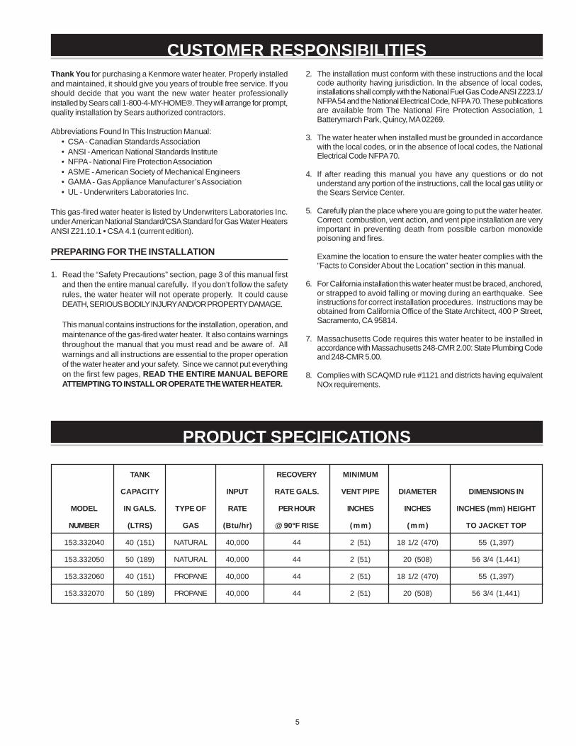
TANK RECOVERY MINIMUM
CAPACITY INPUT RATE GALS. VENT PIPE DIAMETER DIMENSIONS IN
MODEL IN GALS. TYPE OF RATE PER HOUR INCHES INCHES INCHES (mm) HEIGHT
NUMBER (LTRS) GAS (Btu/hr) @ 90°F RISE (mm) (mm) TO JACKET TOP
153.332040 40 (151) NATURAL 40,000 44 2 (51) 18 1/2 (470) 55 (1,397)
153.332050 50 (189) NATURAL 40,000 44 2 (51) 20 (508) 56 3/4 (1,441)
153.332060 40 (151) PROPANE 40,000 44 2 (51) 18 1/2 (470) 55 (1,397)
153.332070 50 (189) PROPANE 40,000 44 2 (51) 20 (508) 56 3/4 (1,441)
Thank You for purchasing a Kenmore water heater. Properly installedand maintained, it should give you years of trouble free service. If youshould decide that you want the new water heater professionallyinstalled by Sears call 1-800-4-MY-HOME®. They will arrange for prompt,quality installation by Sears authorized contractors.
Abbreviations Found In This Instruction Manual:• CSA - Canadian Standards Association• ANSI - American National Standards Institute• NFPA - National Fire Protection Association• ASME - American Society of Mechanical Engineers• GAMA - Gas Appliance Manufacturer’s Association• UL - Underwriters Laboratories Inc.
This gas-fired water heater is listed by Underwriters Laboratories Inc.under American National Standard/CSA Standard for Gas Water HeatersANSI Z21.10.1 • CSA 4.1 (current edition).
PREPARING FOR THE INSTALLATION
1. Read the “Safety Precautions” section, page 3 of this manual firstand then the entire manual carefully. If you don’t follow the safetyrules, the water heater will not operate properly. It could causeDEATH, SERIOUS BODILY INJURY AND/OR PROPERTY DAMAGE.
This manual contains instructions for the installation, operation, andmaintenance of the gas-fired water heater. It also contains warningsthroughout the manual that you must read and be aware of. Allwarnings and all instructions are essential to the proper operationof the water heater and your safety. Since we cannot put everythingon the first few pages, READ THE ENTIRE MANUAL BEFOREATTEMPTING TO INSTALL OR OPERATE THE WATER HEATER.
2. The installation must conform with these instructions and the localcode authority having jurisdiction. In the absence of local codes,installations shall comply with the National Fuel Gas Code ANSI Z223.1/NFPA 54 and the National Electrical Code, NFPA 70. These publicationsare available from The National Fire Protection Association, 1Batterymarch Park, Quincy, MA 02269.
3. The water heater when installed must be grounded in accordancewith the local codes, or in the absence of local codes, the NationalElectrical Code NFPA 70.
4. If after reading this manual you have any questions or do notunderstand any portion of the instructions, call the local gas utility orthe Sears Service Center.
5. Carefully plan the place where you are going to put the water heater.Correct combustion, vent action, and vent pipe installation are veryimportant in preventing death from possible carbon monoxidepoisoning and fires.
Examine the location to ensure the water heater complies with the“Facts to Consider About the Location” section in this manual.
6. For California installation this water heater must be braced, anchored,or strapped to avoid falling or moving during an earthquake. Seeinstructions for correct installation procedures. Instructions may beobtained from California Office of the State Architect, 400 P Street,Sacramento, CA 95814.
7. Massachusetts Code requires this water heater to be installed inaccordance with Massachusetts 248-CMR 2.00: State Plumbing Codeand 248-CMR 5.00.
8. Complies with SCAQMD rule #1121 and districts having equivalentNOx requirements.
CUSTOMER RESPONSIBILITIES
PRODUCT SPECIFICATIONS

6
Materials NeededTo simplify the installation Sears has available the installation parts shown below. You may or may not need all of these materials,depending on your type of installation.
WATER HEATER INSTALLATION KIT WITHFLEXIBLE CONNECTORS FOR 3/4”(19.05 mm) OR 1/2” (12.7 mm) THREADED ORCOPPER PLUMBING AND FLEXIBLE GASCONNECTOR WITH FITTINGS.
EXPANSION TANKS FORTHERMAL EXPANSIONCONDITIONS AVAILABLEIN 2 GALLONS(7.6 LITERS) AND5 GALLONS (18.9 LITERS)CAPACITY THROUGHLOCAL SEARS STORE ORSERVICE CENTER.
DRAIN PANS AVAILABLE IN 20”(508 mm) DIAMETER FORWATER HEATERS HAVING ADIAMETER 18” (457 mm) ORLESS, 24” (610mm) DIAMETERFOR WATER HEATERS HAVINGA DIAMETER 22” (559 mm) ORLESS AND AVAILABLE IN 28”(711 mm) DIAMETER FORWATER HEATERS HAVING ADIAMETER 26” (660 mm) ORLESS.
Basic ToolsYou may or may not need all these tools, depending on yourtype of installation. These tools can be purchased at your localSears Store.
• Pipe Wrenches (2) 14” (356 mm)• Screwdriver• Tin Snips• 6’ (1.82 m) Tape or Folding Ruler• Garden Hose• Drill• Pipe Dope or Teflon Tape
Additional Tools NeededWhen Sweat Soldering• Tubing Cutters or Hacksaw• Propane Tank• Soft Solder• Solder Flux• Emery Cloth• Wire Brushes
SLOT-HEAD SCREWDRIVER
PHILLIPS SCREWDRIVERTIN SNIPS
PIPE WRENCH
PIPE DOPE(SQUEEZE TUBE)
USE FOR WATER AND GASCONNECTIONS
DRILL
GARDEN HOSE 6 FOOT TAPE
ROLL OF TEFLONTAPE (USE ONLY ON
WATER CONNECTIONS)
HACKSAW
3/4” (19 mm) WIRE BRUSH
1/2” (13 mm) WIRE BRUSHSOLDER
FLUXROLL OF LEAD-FREE
SOFT SOLDER
TUBING CUTTERPROPANETORCH
ROLL OFEMERY CLOTH
MATERIALS AND BASIC TOOLS NEEDED

7
TYPICAL INSTALLATIONGET TO KNOW YOUR WATER HEATER - GAS MODELS
A Vent Pipe–ExhaustB Vent TerminalC Vent Adapter-Rubber BootD Blower AssemblyE Cold Water InletF Inlet Water Shut-off ValveG UnionH Inlet Dip TubeJ Anode**
FIGURE 1.
K Hot Water OutletL Outlet Receptacle (115 VAC)M Temperature-Pressure Relief ValveN FlueO Flue Baffle Assembly**P InsulationQ Control HarnessR Rating PlateS Gas SupplyT Manual Gas Shut-off ValveU Ground Joint Union
V Drip Leg (Sediment Trap)W Drain ValveX Gas Valve-ThermostatY Drain PanZ Air Intake Screen - Base Pan
AA Inner DoorBB Outer DoorCC HSI Burner AssemblyDD Air Intake Screen -
Blower AssemblyEE FV Sensor Assembly
NATURAL HOT SURFACE IGNITER & MAIN BURNER
HOTSURFACEIGNITOR
SENSOR
PROPANE HOT SURFACE IGNITER & MAIN BURNER
TEMPERATURE INDICATORS
TEMPERATURE ADJUSTMENT BUTTONS
HOTSURFACEIGNITOR
SENSOR
*CAUTION: 115 VAC IN CONTROL HARNESS AND INSIDE OUTER DOOR
* ALL PIPING MATERIALS TO BE SUPPLIED BY CUSTOMERS.** LOCATED UNDER THE BLOWER ASSEMBLY.
GAS MODELSWITH HOT SURFACE IGNITION& 2", 3" OR 4" PVC VENT CAPABILITY

8
1. Turn “OFF” the gas supply to the waterheater.
If the main gas line Shut-off valveserving all gas appliances is used, alsoshut “OFF” the gas at each appliance.Leave all gas appliances shut “OFF”until the water heater installation iscompleted, see Figures 2 and 3.
2. Turn “OFF” the water supply to thewater heater at the water shut offvalve or water meter. Someinstallations require that the water beturned off to the entire house, seeFigures 2 and 4.
FIGURE 2.
Removing the Old Water Heater
FIGURE 3.
FIGURE 4.
3. Check again to make sure the gas supply is “OFF” to the waterheater. Then disconnect the gas supply connection from the gascontrol valve.
4. Attach a hose to the water heater drainvalve and put the other end in a floordrain or outdoors. Open the waterheater drain valve. Open a nearby hotwater faucet which will relievepressure in the water heater and speeddraining. The water passing out of thedrain valve may be extremely hot. Toavoid being scalded, make sure allconnections are tight and that the waterflow is directed away from any person,see Figures 2 and 5.
FIGURE 5.
5. Disconnect the vent pipe from the blower assembly where it connectsto the water heater. In most installations the vent pipe can be lifted offafter any screw or other attached devices are removed. Make sureexisting vent complies with maximum and minimum vent lengths onpage 17.
6. If you have copper piping to the water heater, the two copper waterpipes can be cut with a hacksaw approximately four inches awayfrom where they connect to the water heater, see Figure 6. This willavoid cutting off pipes too short. Additional cuts can be made later ifnecessary. Disconnect the temperature-pressure relief valve drainline. When the water heater is drained, disconnect the hose from thedrain valve. Close the drain valve. The water heater is now completelydisconnected and ready to be removed.
FIGURE 6.
If you have galvanized pipes to the water heater, loosen the twogalvanized pipes with a pipe wrench at the union in each line. Alsodisconnect the piping remaining to the water heater, see Figure 7.These pieces should be saved since they may be needed whenreconnecting the new water heater. Disconnect the temperature-pressure relief valve drain line. When the water heater is drained,disconnect the hose from the drain valve. Close the drain valve.The water heater is now completely disconnected and ready to beremoved. Mineral buildup or sediment may have accumulated in theold water heater. This causes the water heater to be much heavierthan normal and this residue, if spilled out, could cause staining.
FIGURE 7.
INSTALLATION INSTRUCTIONS

9
FACTS TO CONSIDER ABOUT THE LOCATION
Carefully choose an indoor location for the new water heater, becausethe placement is a very important consideration for the safety of theoccupants in the building and for the most economical use of the appliance.This water heater is not for use in manufactured (mobile) homesor outdoor installation.
Whether replacing an old water heater or putting the water heater in anew location, the following critical points must be observed:1. Select a location indoors as close as practical to the vent terminal or
location to which the water heater vent piping is going to be connected,and as centralized with the water piping system as possible.
2. Selected location must provide adequate clearances for servicingand proper operation of the water heater.
Installation of the water heater must be accomplished in such a mannerthat if the tank or any connections should leak, the flow will not causedamage to the structure. For this reason, it is not advisable to install thewater heater in an attic or upper floor. When such locations cannot beavoided, a suitable drain pan should be installed under the water heater.Drain pans are available at your local hardware store. Such a drain panmust have a minimum length and width of at least 2" (5.1 cm) greater thanthe water heater dimensions and must be piped to an adequate drain.The pan must not restrict combustion air flow.
Water heater life depends upon water quality, water pressure and theenvironment in which the water heater is installed. Water heaters aresometimes installed in locations where leakage may result in propertydamage, even with the use of a drain pan piped to a drain. However,unanticipated damage can be reduced or prevented by a leak detector orwater shut-off device used in conjunction with a piped drain pan. Thesedevices are available from some plumbing supply wholesalers andretailers, and detect and react to leakage in various ways:
• Sensors mounted in the drain pan that trigger an alarm or turn off theincoming water to the water heater when leakage is detected.
• Sensors mounted in the drain pan that turn off the water supply to theentire home when water is detected in the drain pan.
• Water supply shut-off devices that activate based on the waterpressure differential between the cold water and hot water pipesconnected to the water heater.
• Devices that will turn off the gas supply to a gas water heater while atthe same time shutting off its water supply.
INSTALLATIONS IN AREAS WHERE FLAMMABLE LIQUIDS (VAPORS)ARE LIKELY TO BE PRESENT OR STORED (GARAGES, STORAGE ANDUTILITY AREAS, ETC.): Flammable liquids (such as gasoline, solvents,propane (LP or butane, etc.) and other substances (such as adhesives,etc.) emit flammable vapors which can be ignited by a gas water heater’shot surface igniter or main burner. The resulting flashback and fire cancause death or serious burns to anyone in the area. This water heater isequipped with a FV sensor for detecting the presence of flammablevapors, see Figure 8. When the sensor detects those vapors, the unitwill shut down and not operate. Should this happen, please refer to thetroubleshooting guide on pages 29-30. Even though this water heater isa flammable vapors ignition resistant water heater and is designed toreduce the chances of flammable vapors being ignited, gasoline andother flammable substances should never be stored or used in the samevicinity or area containing a gas water heater or other open flame orspark producing appliance.
FIGURE 8.
Also, the water heater must be located and/or protected so it is notsubject to physical damage by a moving vehicle.
This water heater must not be installed directly on carpeting. Carpetingmust be protected by metal or wood panel beneath the appliance extendingbeyond the full width and depth of the appliance by at least 3" (7.6 cm) inany direction, or if the appliance is installed in an alcove or closet, theentire floor must be covered by the panel. Failure to heed this warningmay result in a fire hazard.
Minimum clearances between the water heater and combustibleconstruction are 0 inch at the sides and rear, 5" (12.7 cm) from the front

10
and 12" (30.5 cm) from the top. (Standard clearance.) If clearancesstated on the heater differ from standard clearances, install water heateraccording to clearances stated on the heater.
Adequate clearance for servicing this appliance should be consideredbefore installation, such as changing the anodes, etc.
A minimum clearance of 5" (12.7 cm) must be allowed for access toreplaceable parts such as the thermostats, drain valve and relief valve.
When installing the heater, consideration must be given to proper location.Location selected should be as close to the wall as practicable and ascentralized with the water piping system as possible.
FIGURE 9.
A gas water heater cannot operate properly without the correct amountof air for combustion. Do not install in a confined area such as a closet,unless you provide air as shown in the “Facts to Consider About theLocation” section. Never obstruct the flow of ventilation air. If youhave any doubts or questions at all, call your gas supplier. Failure toprovide the proper amount of combustion air can result in a fire orexplosion and cause death, serious bodily injury, or property damage.
FIGURE 10.
If this water heater will be used in beauty shops, barber shops, cleaningestablishments, or self-service laundries with dry cleaning equipment,it is imperative that the water heater or water heaters be installed sothat combustion and ventilation air be taken from outside these areas.
Propellants of aerosol sprays and volatile compounds, (cleaners,chlorine based chemicals, refrigerants, etc.) in addition to being highly
flammable in many cases, will also react to form corrosive hydrochloricacid when exposed to the combustion products of the water heater.The results can be hazardous, and also cause product failure.
INSULATION BLANKETS
Insulation blankets are available to the general public for external useon gas water heaters but are not necessary with Kenmore products.The purpose of an insulation blanket is to reduce the standby heat lossencountered with storage tank heaters. Your Kenmore water heatermeets or exceeds the National Appliance Energy Conservation Actstandards with respect to insulation and standby loss requirements,making an insulation blanket unnecessary.
Should you choose to apply an insulation blanket to this heater, youshould follow these instructions (For identification of componentsmentioned below, see Figure 1). Failure to follow these instructionscan restrict the air flow required for proper combustion, potentiallyresulting in fire, asphyxiation, serious personal injury or death.
• Do not apply insulation to the top of the water heater, as this willinterfere with safe operation of the blower assembly.
• Do not cover the outer door, thermostat or temperature & pressurerelief valve.
• Do not allow insulation to come within 2" (5.1 cm) of the floor toprevent blockage of combustion air flow to the burner.
• Do not cover the instruction manual. Keep it on the side of thewater heater or nearby for future reference.
• Do obtain new warning and instruction labels from Searsfor placement on the blanket directly over the existing labels.
• Do inspect the insulation blanket frequently to make certain itdoes not sag, thereby obstructing combustion air flow.
COMBUSTION AIR AND VENTILATION FORAPPLIANCES LOCATED IN UNCONFINED SPACES
UNCONFINED SPACE is space whose volume is not less than50 cubic feet per 1,000 Btu per hour (4.8 cubic meters per kW) of theaggregate input rating of all appliances installed in that space. Roomscommunicating directly with the space in which the appliances areinstalled, through openings not furnished with doors, are considered apart of the unconfined space.
In unconfined spaces in buildings, infiltration may be adequate to provideair for combustion, ventilation and dilution of flue gases. However, inbuildings of tight construction (for example, weather stripping, heavilyinsulated, caulked, vapor barrier, etc.), additional air may need to beprovided using the methods described in “Combustion Air and Ventilationfor Appliances Located in Confined Spaces.”
COMBUSTION AIR AND VENTILATION FORAPPLIANCES LOCATED IN CONFINED SPACES
CONFINED SPACE is a space whose volume is less than 50 cubic feetper 1,000 Btu per hour (4.8 cubic meters per kW) of the aggregateinput rating of all appliances installed in that space.

11
Chemical vapor corrosion of the flue, blower assembly and vent systemmay occur if air for combustion contains certain chemical vapors.Spray can propellants, cleaning solvents, refrigerator and air conditionerrefrigerants, swimming pool chemicals, calcium and sodium chloride,waxes, bleach and process chemicals are typical compounds whichare potentially corrosive.
A. ALL AIR FROM INSIDE BUILDINGS: (See Figure 10 and 11)
The confined space shall be provided with two permanent openingscommunicating directly with an additional room(s) of sufficient volumeso that the combined volume of all spaces meets the criteria for anunconfined space. The total input of all gas utilization equipment installedin the combined space shall be considered in making this determination.Each opening shall have a minimum free area of one square inch per1,000 Btu per hour (22 cm2/kW) of the total input rating of all gas utilizationequipment in the confined space, but not less than 100 square inches(645 cm2). One opening shall commence within 12 inches(31 cm) of the top and one commencing within 12 inches (31 cm) of thebottom of the enclosures.
FIGURE 11.
B. ALL AIR FROM OUTDOORS: (See Figures 12, 13 and 14)
The confined space shall be provided with two permanent openings,one commencing within 12 inches (31 cm) of the top and onecommencing within 12 inches (31 cm) from the bottom of the enclosure.The openings shall communicate directly, or by ducts, with the outdoorsor spaces (crawl or attic) that freely communicate with the outdoors.
1. When directly communicating with the outdoors, each opening shallhave a minimum free area of 1 square inch per 4,000 Btu per hour(5.5 cm2/kW) of total input rating of all equipment in the enclosure,see Figure 12.
FIGURE 12.
2. When communicating with the outdoors through vertical ducts, eachopening shall have a minimum free area of 1 square inch per 4,000Btu per hour (5.5 cm2/kW) of total input rating of all equipment in theenclosure, see Figure 13.
3. When communicating with the outdoors through horizontal ducts,each opening shall have a minimum free area of 1 square inch per2,000 Btu per hour (11 cm2/kW)) of total input rating of all equipmentin the enclosure, see Figure 14.
FIGURE 13.
4. When ducts are used, they shall be of the same cross-sectionalarea as the free area of the openings to which they connect. Theminimum short side dimension of rectangular air ducts shall not beless than 3 inches (7.6 cm), see Figure 14.
FIGURE 14.
5. Louvers and Grilles: In calculating free area, consideration shall begiven to the blocking effect of louvers, grilles or screens protectingopenings. Screens used shall not be smaller than 1/4 inch(6.4 mm) mesh. If the free area through a design of louver or grilleis known, it should be used in calculating the size opening requiredto provide the free area specified. If the design and free area is notknown, it may be assumed that wood louvers will be 20-25 percentfree area and metal louvers and grilles will have 60-75 percent freearea. Louvers and grilles shall be fixed in the open position orinterlocked with the equipment so that they are opened automaticallyduring equipment operation.
6. Special Conditions Created by Mechanical Exhausting or Fireplaces:operation of exhaust fans, ventilation systems, clothes dryers orfireplaces may create conditions requiring special attention to avoidunsatisfactory operation of installed gas utilization equipment.

12
Toxic chemicals, such as those used for boiler treatment shall not beintroduced into this system.
When the system requires water at temperatures higher than requiredfor domestic water purposes, a tempering valve must be installed. Pleaserefer to Figure 15 for suggested piping arrangement.
Water supply systems may, because of such events as high linepressure, frequent cut-offs, the effects of water hammer among others,have installed devices such as pressure reducing valves, check valves,back flow preventers, etc. to control these types of problems. Whenthese devices are not equipped with an internal by-pass, and no othermeasures are taken, the devices cause the water system to be closed.As water is heated, it expands (thermal expansion) and closed systemsdo not allow for the expansion of heated water.
The water within the water heater tank expands as it is heated andincreases the pressure of the water system. If the relieving point of thewater heater’s temperature-pressure relief valve is reached, the valvewill relieve the excess pressure. The temperature-pressure reliefvalve is not intended for the constant relief of thermalexpansion. This is an unacceptable condition and must be corrected.It is recommended that any devices installed which could create a closedsystem have a by-pass and/or the system have an expansion tank torelieve the pressure built by thermal expansion in the water system.Thermal expansion tanks are available from Sears stores and throughthe Sears Service Centers. Contact the local plumbing inspector, watersupplier and/or the Sears Service Center for assistance in controllingthese situations.
NOTE: To protect against untimely corrosion of hot and coldwater fittings, it is strongly recommended that di-electric unionsor couplings be installed on this water heater when connectedto copper pipe.
Figure 16 shows the typical attachment of the water piping to the waterheater. The water heater is equipped with 3/4 inch NPT waterconnections.
NOTE: If using copper tubing, solder tubing to an adapter beforeattaching the adapter to the cold water inlet connection. Do notsolder the cold water supply line directly to the cold water inlet.It will harm the dip tube and damage the tank.
• Look at the top cover of the water heater. The water outlet is marked“HOT”. Put two or three turns of teflon tape around the threaded endof the threaded-to-sweat coupling and around both ends of the 3/4”NPT threaded nipple. Using flexible connectors, connect the hot waterpipe to the hot water outlet on the water heater.
• Look at the top of the water heater. The cold water inlet is marked“COLD”. Put two or three turns of teflon tape around the threadedend of the threaded-to-sweat coupling and around both ends of the3/4” NPT threaded nipple. Using flexible connectors, connect the coldwater pipe to the cold water inlet of the water heater.
WATER PIPING
HOTTER WATER CAN SCALD:Water heaters are intended to produce hot water. Water heated to atemperature which will satisfy space heating, clothes washing, dishwashing, cleaning and other sanitizing needs can scald and permanentlyinjure you upon contact. Some people are more likely to be permanentlyinjured by hot water than others. These include the elderly, children, theinfirm, or physically/mentally handicapped. If anyone using hot water inyour home fits into one of these groups or if there is a local code or statelaw requiring a certain temperature water at the hot water tap, then youmust take special precautions. In addition to using the lowest possibletemperature setting that satisfies your hot water needs, a means suchas a *mixing valve, shall be used at the hot water taps used by thesepeople or at the water heater, see Figure 15. Valves for reducing pointof use temperature by mixing cold and hot water are also available:
FIGURE 15.
Consult Sears Service Center. Follow manufacturer’s instructions forinstallation of the valves. Before changing the factory setting on thethermostat, read the “Temperature Regulation” section in this manual.
This water heater shall not be connected to any heating system orcomponent or used as a non-potable water heating appliance.
All piping components connected to this unit shall be suitable for usewith potable water.

13
INSTALLATION COMPLETED USING INSTALLATION KIT
FIGURE 16.
T & P Valve and Pipe Insulation (if supplied)
Remove insulation for T & P valve and pipe connections from carton.
FIGURE 17.
Fit pipe insulation over the incoming cold water line and the hot waterline. Make sure that the insulation is against the top cover of the heater.
Fit T & P valve insulation over valve. Make sure that the insulation doesnot interfere with the lever of the T & P valve.
Secure all insulation using tape.
TEMPERATURE-PRESSURE RELIEF VALVE
This heater is provided with a properly certified combinationtemperature - pressure relief valve by the manufacturer.
The valve is certified by a nationally recognized testing laboratory thatmaintains periodic inspection of production of listed equipment ofmaterials as meeting the requirements for Relief Valves and AutomaticGas Shut-off Devices for Hot Water Supply Systems, ANSI Z21.22 • CSA4.4, and the code requirements of ASME.
If replaced, the valve must meet the requirements of local codes, but notless than a combination temperature and pressure relief valve certifiedas indicated in the above paragraph.
The valve must be marked with a maximum set pressure not to exceedthe marked hydrostatic working pressure of the water heater (150 psi = 1,035 kPa) and a discharge capacity not less than the waterheater input rate as shown on the model rating plate.
For safe operation of the water heater, the relief valve must not beremoved from its designated opening nor plugged.
The temperature-pressure relief valve must be installed directly into thefitting of the water heater designed for the relief valve. Position the valvedownward and provide tubing so that any discharge will exit only within6 inches (15.2 cm) above, or at any distance below the structural floor.Be certain that no contact is made with any live electrical part. Thedischarge opening must not be blocked or reduced in size under anycircumstances. Excessive length, over 30 feet (9.14 m), or use of morethan four elbows can cause restriction and reduce the dischargecapacity of the valve, see Figures 16 or 20.
No valve or other obstruction is to be placed between the relief valveand the tank. Do not connect tubing directly to discharge drain unless a6" (15.2 cm) air gap is provided. To prevent bodily injury, hazard to life,or property damage, the relief valve must be allowed to discharge waterin quantities should circumstances demand. If the discharge pipe is notconnected to a drain or other suitable means, the water flow may causeproperty damage.

14
The Discharge Pipe:• Shall not be smaller in size than the outlet pipe size of the valve, orhave any reducing couplings or other restrictions.
• Shall not be plugged or blocked.• Shall be of material listed for hot water distribution.• Shall be installed so as to allow complete drainage of both thetemperature-pressure relief valve, and the discharge pipe.
• Shall terminate at an adequate drain.• Shall not have any valve between the relief valve and tank.
The temperature-pressure relief valve must be manually operated at leastonce a year. Caution should be taken to ensure that (1) no one is in frontof or around the outlet of the temperature-pressure relief valve dischargeline, and (2) the water manually discharged will not cause any bodily injuryor property damage because the water may be extremely hot.
If after manually operating the valve, it fails to completely reset andcontinues to release water, immediately close the cold water inlet tothe water heater, follow the draining instructions, and replace thetemperature-pressure relief valve with a new one.
GAS PIPING
Make sure the gas supplied is the same type listed on the model ratingplate. The inlet gas pressure must not exceed 14 inch water column (3.5kPa) for natural and propane gas (L.P.). The minimum inlet gas pressureshown on the rating plate is that which will permit firing at rated input.
All gas piping must comply with local codes and ordinances or with theNational Fuel Gas Code (ANSI Z223.1/ NFPA-54) whichever applies. Copperand brass tubing and fittings (except tin lined copper tubing) shall not be used.
If the gas control valve is subjected to pressures exceeding 1/2 psi(3.5 kPa), the damage to the gas control valve could result in a fire orexplosion from leaking gas.
If the main gas line Shut-off serving all gas appliances is used, alsoturn “off” the gas at each appliance. Leave all gas appliances shut“off” until the water heater installation is complete.
A gas line of sufficient size must be run to the water heater. Consultthe current edition of National Fuel Gas Code ANSI Z223.1/NFPA 54 andyour gas supplier concerning pipe size.
There must be:• A readily accessible manual shut off valve in the gas supply line
serving the water heater, and• A drip leg (sediment trap) ahead of the gas control valve to help
prevent dirt and foreign materials from entering the gas control valve.• A flexible gas connector or a ground joint union between the shut off
valve and control valve to permit servicing of the unit.
Be sure to check all the gas piping for leaks before lighting the waterheater. Use a soapy water solution, not a match or open flame. Rinseoff soapy solution and wipe dry.
Water heaters covered in this manual have been tested and approvedfor installation at elevations up to 7,700 feet (2,347 m) above sea level.When installed at elevations above 7,700 feet (2,347 m), input ratingshould be reduced at the rate of 4 percent for each 1,000 feet (305 m)above sea level which requires replacement of the burner orifice inaccordance with National Fuel Gas Code ANSI Z223.1/NFPA 54. Contactyour local gas supplier for further information.
Failure to replace the standard orifice with a high altitude orifice wheninstalled at elevations above 7,700 feet (2,347 m) could result inimproper and inefficient operation of the appliance, producing carbonmonoxide gas in excess of safe limits. This could result in seriousinjury or death. Contact your gas supplier for any specific changeswhich may be required in your area.
Use pipe joint compound or teflon tape marked as being resistant to theaction of petroleum [Propane (L.P.)] gases.

15
The appliance and its gas connection must be leak tested before placingthe appliance in operation.
The appliance and its individual Shut-off valve shall be disconnectedfrom the gas supply piping system during any pressure testing of thatsystem at test pressures in excess of 1/2 pound per square inch(3.5 kPa). It shall be isolated from the gas supply piping system byclosing its individual manual Shut-off valve during any pressure testingof the gas supply piping system at test pressures equal to or less than1/2 pound per square inch (3.5 kPa).
Connecting the gas piping to the gas control valve of the water heater can beaccomplished by either of the two methods shown in Figures 18 and 19.
FIGURE 18. GAS PIPING WITHFLEXIBLE CONNECTOR.
FIGURE 19. GAS PIPING WITH ALLBLACK IRON PIPE TO GAS CONTROL.
SEDIMENT TRAPS
Contaminants in the gas lines may cause improper operation of the gascontrol valve that may result in fire or explosion. Before attaching thegas line be sure that all gas pipe is clean on the inside. To trap any dirtor foreign material in the gas supply line, a drip leg (sometimes called asediment trap) must be incorporated in the piping. The drip leg must bereadily accessible. Install in accordance with the “Gas Piping” section.Refer to the current edition of the National Fuel Gas Code,ANSI Z223.1/NFPA 54.
A sediment trap shall be installed as close to the inlet of the waterheater as practical at the time of water heater installation. The sedimenttrap shall be either a tee fitting with a capped nipple in the bottom outletor other device recognized as an effective sediment trap. If a tee fittingis used, it shall be installed in conformance with one of the methods ofinstallation shown in Figures 18 and 19.
FIGURE 20.
FILLING THE WATER HEATER
Never use this water heater unless it is completely full of water. Toprevent damage to the tank, the tank must be filled with water. Watermust flow from the hot water faucet before turning “ON” gas to thewater heater.
To fill the water heater with water:
1. Close the water heater drain valve by turning the handle to the right(clockwise). The drain valve is on the lower front of the water heater.
2. Open the cold water supply valve to the water heater.
NOTE: The cold water supply valve must be left open whenthe water heater is in use.
3. To insure complete filling of the tank, allow air to exit by opening thenearest hot water faucet. Allow water to run until a constant flowis obtained. This will let air out of the water heater and the piping.
4. Check all water piping and connections for leaks. Repair as needed.
BLOWER ASSEMBLY INSTALLATION
SEQUENCE OF INSTALLATION
1. This power vented water heater comes with the blower assembly installed.
2 After the unit is set in place, make sure the blower assembly is stillmounted securely and the air intake screen of the blower assemblyis installed in the dilution air opening. Also make sure the drain portof the rubber boot vent adapter is capped off. Lastly, make surethere is no damage to the blower.
3. Make sure there is no packing material in the discharge of theblower or the intake of the dilution air restrictor, see Figure 21.

16
4. Make sure that the plastic tubing is still attached from the air pressureswitch to the port on the blower housing. Make sure the plastictubing is not folded anywhere between the pressure switch andthe blower housing.
5. Make sure the ON/OFF switch is in the OFF position and that theouter harness is connected from the blower control box to theconnector on the bottom side of the gas valve.
6. If the outer harness is not factory installed, make sure the ON/OFF switchis in the OFF position and then connect the harness from the blowercontrol box to the connector on the bottom side of the gas valve.
7. Do not plug in power cord until vent system is completely installed.This power vent heater operates on 110-120 Vac, therefore agrounded outlet must be within reach of the six (6) foot (1.8 m)flexible power cord supplied with the unit (see Figure 1). The powercord supplied may be used only where local codes permit. If localcodes do not permit the use of a flexible power supply cord:
a.) Make sure the unit is unplugged from wall outlet. Remove screwsand open panel on front of control box.
b.) Cut the flexible power cord, leaving enough to be able to makeconnections and remove the strain relief fitting from box.
c.) Install suitable conduit fitting in side of enclosure and then follow(d.) and (e.) below.
d.) Splice field wiring into existing wiring using code authorized method(wire nuts, etc.).
e.) Be certain that neutral and live connections are not reversed whenmaking these connections.
f.) Close panel on the side of control box, make sure that access panelis secured shut.

17
VENT CONNECTIONS TO BLOWER ASSEMBLY
Figure 21 shows the optimal placement of the 2" to 3" or 3" to 4" reducer;however, the vent can be reduced at any point in the vent system as longas the maximum vent length is not exceeded.
FIGURE 21.
VENTING AND INSTALLATION
Plan the layout of the vent system from the vent termination to the waterheater considering all of the 90° and 45° elbows plus the number of feetof pipe that would be needed to install the total vent system. The waterheater must be vented to the outdoors as described in these instructions.DO NOT connect this water heater to an existing vent or chimney. It mustbe vented separately from all other appliances. Nonmetallic vent may beused if it has “Heat Deflection Temperature” (HDT@66 psi) or 455 kPa ofat least 157°F or 69°C. Typical nonmetallic vent materials meeting thisrequirement are: PVC (Schedule 40, ASTM D-1785), Coex Cellular Core(Schedule 40, ASTM F-441), CPVC (Schedule 40, ASTM D-2846), ABS(Schedule 40, ASTM D-2661). The fittings, other than the supplied VentTermination should be equivalent to the following: PVC (Schedule 40,DWV, ASTM D-2665), CPVC (Schedule 40, DWV, ASTM F-438), ABS(Schedule 40 DWV, ASTM D-2661).
The cement used should be as recommended by the vent pipemanufacturer. See the instructions on pages 20 and 21 for the propermethod of cutting and cementing the PVC pipe and fittings.
The unit may be vented horizontally through a wall or vertically throughthe roof. Pipe runs must be adequately supported along both verticaland horizontal runs as follows:
• For Schedule 40, 2" PVC, ABS, Coex Cellular Core vent pipe: Every3 feet (0.9 m).
• For Schedule 40, 3" PVC, ABS, Coex Cellular Core vent pipe: Every3.5 feet (1.1 m).
• For Schedule 40, 4" PVC, ABS, Coex Cellular Core vent pipe: Every4 feet (1.2 m).
• For Schedule 40, 2" CPVC vent pipe: Every 5 feet (1.5 m).
• For Schedule 40, 3" CPVC vent pipe: Every 6 feet (1.8 m).
• For Schedule 40, 4" CPVC vent pipe: Every 6.5 feet (2.0 m).
It is imperative that the first hanger (or support) be located on the horizontalrun immediately adjacent to the first 90-degree elbow from the verticalrise. Support method used should isolate the vent pipe from the floorjoists or other structural members to prevent the transmission of noiseand vibration. Do not support, pin, or otherwise secure the ventingsystem in a way that restricts the normal thermal expansion andcontraction of the chosen venting material.
If the water heater is being installed as a replacement for an existingpower vented heater in pre-existing venting, a thorough inspection ofthe existing venting system must be performed prior to any installationwork. Verify that the correct material as detailed above has beenused, and that the minimum or maximum vent lengths and terminallocation as detailed in this manual have been met. Carefully inspect theentire venting system for any signs of cracks or fractures, particularlyat the joints between elbows and other fittings and the straight runs ofvent pipe. Check the system for signs of sagging or other stresses inthe joints as a result of misalignment of any components in the system.If any of these conditions are found, they must be corrected inaccordance with the venting instructions in this manual beforecompleting the installation and putting the water heater into service.
Except where instructed in this manual, the mixing of 2", 3" and 4" ventpipe is NOT ALLOWED. If 2" pipe is to be used, then a 2" to 3" bell reduceris recommended. Figure 21 shows the recommended location for thebell reducer. If the bell reducer is located at the rubber boot on theblower assembly, then a short section of 3" vent pipe needs to beinstalled in the rubber boot for proper connection of the 2" to 3" bellreducer. That length can be the minimum length required for the connection.
If 4" pipe is to be used, then a 3" to 4" bell reducer is recommended.Figure 21 shows the recommended location for the bell reducer. If thebell reducer is located at the rubber boot on the blower assembly, thena short section of 3" vent pipe needs to be installed in the rubber bootfor proper connection of the 3" to 4" bell reducer. That length can bethe minimum length required for the connection.
The water heaters covered by this manual are supplied with a 2" Schedule40 PVC 22.5° Vent Terminal. If you decide to vent with 3" or 4" pipe, aSchedule 40 DWV 45° Vent Terminal must be used. For your convenience,we have included a screen for both 3" and 4" Vent Terminals.
The vent piping should be connected to the blower with a rubberadapter and secured with hose clamps. The adapter and clamps areprovided with the heater.
Even though the flue gas temperature leaving the blower is between140°F (69°C) and 175°F (79°C), some installations will have watervapor condense in the vent piping. If this occurs, then adequate meansof draining and disposing of the condensate needs to be made by the installer.
CONDENSATION
Condensate formation does not occur in all installations of power ventedwater heaters, but should be protected against on installations where itcan form in the venting system. Condensation in the venting system ofpower vented water heaters is dependent upon installation conditionsincluding, but not limited to ambient temperature and humidity of installationlocation, ambient temperature and humidity of venting space, ventdischarge and slope, and product usage. In certain conditions, installationsin unconditioned space or having long horizontal or vertical vent runsmay accumulate condensate. In these conditions, the vent pipe shouldbe sloped downward away from the blower assembly 1/4" (6.4 mm) perfive feet (1.5 m) of pipe but not more than 1 1/2" (3.8 cm) in the total ventlength. If the vent piping is vented level or sloped upwards away fromthe blower assembly, then adequate means for draining and disposingof the condensate needs to be made by the installer (if condensate isdetected). If you have condensate, then a 3/8" drain hose can be connectedto the built-in drain port of the rubber boot on the blower assembly. Foryour convenience, the rubber boot is supplied with a removable cap onthe built-in drain port. Prior to operating the water heater, make sure theremovable cap is installed on the drain port (if a drain hose is not needed).
MAXIMUM VENT LENGTHS
40,000 BTU Units:
For 2" Venting, the maximum equivalent feet of pipe allowedis 40 feet (12.2 m). This does not include the supplied vent terminationfor the water heater. For the 2" venting, one 90° elbow is approximatelyequal to 5 feet (1.5 m). One 45° elbow is approximately equal to 2.5feet (0.8 m). It is recommended that at least 2 feet (0.6 m) of spacingbe used in between all 45° elbows and all 90°elbows.
For 3" Venting, the maximum equivalent feet of pipe allowedis 120 feet (36.6 m). This does not include the Vent Termination (suppliedlocally) for the water heater. For the 3" venting, one 90° elbow isapproximately equal to 5 feet (1.5 m). One 45° elbow is approximatelyequal to 2.5 feet (0.8 m). It is recommended that at least 2 feet (0.6 m)of spacing be used in between all 45° elbows and all 90°elbows.
For 4" Venting, the maximum equivalent feet of pipe allowedis 160 feet (48.8 m). This does not include the Vent Termination (suppliedlocally) for the water heater. For the 4" venting, one 90° elbow isapproximately equal to 8 feet (2.4 m). One 45° elbow is approximatelyequal to 4 feet (1.2 m). It is recommended that at least 2 feet (0.6 m) ofspacing be used in between all 45° elbows and all 90°elbows.

18
VENTING
The vent system must terminate so that proper clearances aremaintained as cited in local codes or the current edition of the NationalFuel Gas Code, ANSI Z223.1/NFPA 54, 7.3.4e and 7.8a,b, as follows:
1. The exit terminals of a mechanical vent system shall be not lessthan 7 feet (2.13 m) above grade when located adjacent to publicwalkways, see Figure 23.
2. A venting system shall terminate at least 3 feet (91 cm) above anyforced air inlet located within 10 feet (3.1 m), see Figure 23.
3. The venting system shall terminate at least 4 feet (1.2 m) below, 4feet (1.2 m) horizontally from or, 12 in. (30 cm) above any door,window or gravity air inlet into any building.
The manufacturer also recommends that the vent termination shouldnot be installed closer than 3 feet (91 cm) from an inside corner of anL shaped structure and not be less than 12 in. (30 cm) above grade.
The vent shall terminate a minimum of 12'' (30.5 cm) above expectedsnowfall level to prevent blockage of vent termination, see Figure 23.
4. In cold climates, it is recommended that vent termination not be mounteddirectly above or within 3 feet (91 cm) horizontally from an oil tank vent orgas meter to avoid potential freeze-up from condensation, see Figure 23.
Plan the vent system layout so that proper clearances are maintainedfrom plumbing and wiring.
Vent pipes serving power vented appliances are classified by buildingcodes as “vent connectors”. Required clearances from combustiblematerials must be provided in accordance with information in this manualunder FACTS TO CONSIDER ABOUT THE LOCATION and VENTTERMINAL INSTALLATIONS, and with the National Fuel Gas Code andlocal codes.
VENT TERMINAL INSTALLATION
1. After the point of termination has been determined, use the coverplate as a template to mark the hole for the vent pipe to insertthrough the wall. BEWARE OF CONCEALED WIRING AND PIPINGINSIDE OF WALL.
2. If the Vent Terminal is being installed on the outside of a finishedwall, it may be easier to mark both the inside and outside wall.Align the holes by drilling a hole through the center of the templatefrom the inside through to the outside. The template can now bepositioned on the outside wall using the drilled hole as a centeringpoint for the template.
3. A) MASONRY SIDE WALLSChisel an opening approximately one half inch larger than themarked circle.
B) WOODEN SIDE WALLSDrill a pilot hole approximately one quarter inch outside of themarked circle. This pilot hole is used as a starting point for asaws-all or sabre saw blade. Cut around the marked circle stayingapproximately one quarter inch outside of the line. (This will allowthe vent pipe to easily slide through the opening. The resultinggap will be covered up by the vent terminal cover plates.) Repeatthis step on inside wall if necessary.
4. When the vent piping cannot pass through an outside wall at aheight greater than or equal to 12" above the ground (or abovesnow accumulation level), then the installation can be modified asshown below.
FIGURE 22.

19
FIGURE 23.
This unit can vent through 2", 3" or 4" nonmetallic pipe and fittings.
The vent pipe installation can be started from either the blower dischargeor the termination wall. Keep in mind the total vent system (pipe andelbows) when installing the vent system, see VENTING ANDINSTALLATION AND MAXIMUM VENT LENGTHS, page 17.
FIGURE 24.
The vent terminal should be kept as close as possible to the outsidewall, but you need to allow at least 1.5" (3.8 cm) of pipe past the wall,for the wall flange and vent terminal to mount on the pipe.
Before the vent terminal is installed, caulk (not supplied) around the pipeon the exterior wall and install the optional wall flange. The flange can beheld to the outside wall by placing some of the caulking on the back of theflange. The wall flange is supplied for decorative purposes only and isnot a requirement for the vent termination (if not needed by the installer).
VERTICAL VENT THROUGH ROOF
This unit is approved for venting through the roof with the type ventterminal that is included with the unit. A proper flashing or “BOOT”should be used to seal the pipe where it exits the roof.
The total vent system should not exceed that which is specified, seeVENTING AND INSTALLATION, page 17.
All of the pipe should be secured as per the instructions in the instructionsin the VENTING AND INSTALLATION, page 17.
VERTICAL VENT TERMINATION RESTRICTIONS
1. Minimum of twelve 12" (30.5 cm) above the roof or twelve 12"(30.5 cm) above the anticipated snow level. Provide proper supportfor all pipe protruding through the roof.
FIGURE 25.2. 4' (1.2 m) from or 1' (0.3 m) above any gable, dormer, or other roof
structure with access to interior of building (i.e.-vent, window etc.).
3. 3' (0.9 m) above any forced air inlet located within 10' (3.0 m).

20
VENT PIPE PREPARATION
1. INITIAL PREPARATION
A. Make sure the solvent cement you are planning to use isdesigned for the specific application you are attempting.
B. Know the physical and chemical characteristics and limitationsof the PVC and CPVC piping materials that you are about to use.
C. Know the reputation of your manufacturer and their products.
D. Know your own qualifications or those of your contractor.The solvent welding technique of joining PVC and CPVC pipeis a specialized skill just as any other pipe fitting technique.
E. Closely supervise the installation and inspect the finishedjob before start-up.
F. Contact the manufacturer, supplier, or competent consultingagency if you have any questions about the application orinstallation of PVC and CPVC pipe.
G. Take the time and effort to do a professional job. Shortcutswill only cause you problems and delays in start-up. By far,the majority of failures in PVC and CPVC systems are theresult of shortcuts and/or improper joining techniques.
2. SELECTION OF MATERIALS
• Cutting Device - Saw or Pipe Cutter
• Deburring Tool, Knife, File, or Beveling Machine (2" and above)
• Brush - Pure Bristle
• Rag - Cotton (Not Synthetic)
• Primer and Cleaner
• Solvent Cement - PVC for PVC Components and CPVC for CPVCComponents
• Containers - Metal or Glass to hold Primer and Cement. Select thetype of PVC or CPVC materials to be used on the basis of theirapplication with respect to chemical resistance, pressure rating,temperature characteristics, etc.
• Insertion Tool - Helpful for larger diameter pipe and fittings 6 inches(15.2 cm) and above.
PRIMER
It is recommended that Tetrahydrofuran (THF) be used to prepare thesurfaces of pipe and fittings for solvent welding. Do not use water,rags, gasoline or any other substitutes for cleaning PVC or CPVCsurfaces. A chemical cleaner such as MEK may be used.
CEMENT
The cement should be a bodied cement of approximately 500 to 1600centipoise viscosity containing 10-20% (by weight) virgin PVC materialsolvated with tetrahydrofuran (THF). Small quantities of dimethyl
formamide (DMF) may be included to act as a retarding agent to extendcuring time. Select the proper cement; Schedule 40 cement should beused for Schedule 40 pipe. Never use all-purpose cements, commercialglues and adhesives or ABS cement to join PVC or CPVC pipe and fittings.
APPLICATORS
Select a suitable pure bristle type paint brush. Use a proper widthbrush or roller to apply the primer and cement (see chart below).Speedy application of cement is important due to its fast dryingcharacteristics. IMPORTANT NOTE: A dauber type applicator shouldonly be used on pipe sizes 2" and below. For larger diameter pipe, abrush or roller must be used.
RECOMMENDED BRUSH* SIZE FOR PRIMERAND CEMENT APPLICATIONS
Nominal Pipe Size Brush Width(IPS) (INS.)
2 1-1/23 1-1/2 - 2-1/2
*USE ONLY NATURAL BRISTLE
3. MAKING THE JOINT
A. CuttingPipe must be squarely cut to allow for the proper interfacing of thepipe end and the fitting socket bottom. This can be accomplishedwith a miter box saw or wheel type cutter. Wheel type cutters arenot generally recommended for larger diameters since they tend toflare the corner of the pipe end. If this type of cutter is used, theflare on the end must be completely removed.
NOTE: Power saws should be specifically designed to cut plastic pipe.
STEP A

21
B. DeburringUse a knife, plastic pipe deburring tool, or file to remove burrs from the endof small diameter pipe. Be sure to remove all burrs from around the insideas well as the outside of the pipe. A slight chamfer (bevel) of about 10°-15° should be added to the end to permit easier insertion of the pipe intothe end of the fitting. Failure to chamfer the edge of the pipe may removecement from the fitting socket, causing the joint to leak.
STEP B
C. Test dry fit of the jointTapered fitting sockets are designed so that an interfaced fit shouldoccur when the pipe is inserted about 1/3 to 2/3 of the way into thesocket. Occasionally, when pipe fitting dimensions are at thetolerance extremes, it will be possible to fully insert dry pipe to thebottom of the fitting socket. When this happens, a sufficient quantityof cement must be applied to the joint to fill the gap between the pipeand fitting. The gap must be filled to obtain a strong, leak-free joint.
D. Inspection, cleaning, primingVisually inspect the inside of the pipe and fitting sockets and removeall dirt, grease or moisture with a clean dry rag. If wiping fails toclean the surfaces, a chemical cleaner must be used. Check forpossible damage such as splits or cracks and replace if necessary.
Depth-of-entryMarking the depth of entry is a way to check if the pipe has reachedthe bottom of the fitting socket in Step F. Measure the fitting depthand mark this distance on the pipe O.D. You may want to addseveral inches to the distance and make a second mark as theprimer and cement will most likely destroy your first one.
Apply primer to the surface of the pipe and fitting socket with a naturalbristle brush. This process softens and prepares the PVC or CPVC forthe solvent cementing step. Move quickly and without hesitation to thecementing procedure while the surfaces are still wet with primer.
E. Application of solvent cement• Apply the solvent cement evenly and quickly around the outside of the
pipe at a width a little greater than the depth of the fitting socket.• Apply a light coat of cement evenly around the inside of the
fitting socket. Avoid puddling.• Apply a second coat of cement to the pipe end.
STEP EF. Joint assembly
Working quickly, insert the pipe into the fitting socket bottom andgive the pipe or fitting a 1/4 turn to evenly distribute the cement. Donot continue to rotate the pipe after it has hit the bottom of the fittingsocket. A good joint will have sufficient cement to make a bead allthe way around the outside of the fitting hub. The fitting will have atendency to slide back while the cement is still wet so hold the jointtogether for about 15 seconds.
STEP F
G. Cleanup and joint movementRemove all excess cement from around the pipe and fitting with adry cotton rag. This must be done while the cement is still soft.
The joint should not be disturbed immediately after the cementingprocedure, and sufficient time should be allowed for proper curingof the joint. Exact drying time is difficult to predict because it dependson variables such as temperature, humidity and cement integrity.For more specific information, you should contact your solventcement manufacturer.
STEP G

22
FOR YOUR SAFETY READ BEFORE OPERATING
WARNING: If you do not follow these instructions exactly, a fire orexplosion may result causing property damage, personal injury or loss oflife.
A. This appliance does not have a pilot. It is equipped withan ignition device which automatically lights the burner.Do NOT try to light the burner by hand.
B. BEFORE OPERATING smell all around the appliance areafor gas. Be sure to smell next to the floor because somegas is heavier than air and will settle on the floor.
WHAT TO DO IF YOU SMELL GAS:• Do not try to light any appliance.• Do not touch any electric switch;
Do not use any phone in your building.• Immediately call your gas supplier from a neighbor’s phone.
Follow the gas supplier’s instructions.
• If you cannot reach your gas supplier, call the firedepartment.
C. Use only your hand to push in the gas control buttons.Never use tools. If the control buttons will not push in,don’t try to repair them, call a qualified service technician.Force or attempted repair may result in a fire or explosion.
D. Do not use this appliance if any part has been underwater. Immediately contact a qualified installer or serviceagency to replace a flooded water heater. Do not attemptto repair the unit! It must be replaced!
OPERATING INSTRUCTIONS
1. Set the thermostat to the lowest setting by first pressing the COOLER and HOTTER buttons together and holdingfor 1 second. Then press the COOLER button until the WARM indicator light appears.
2. Set the ON/OFF switch on the blower control box to the “OFF” position.
3. Turn off all electric power to the appliance if service is to be performed.
BEFORE OPERATING: ENTIRE SYSTEM MUST BE FILLED WITH WATER AND AIR PURGED FROM ALL LINES.
1. STOP! Read the safety information above,on this label.
2. Set the thermostat to the lowest setting by first pressingthe COOLER and HOTTER buttons together andholding for 1 second. Then press the COOLER buttonuntil the WARM indicator light appears.
3. Set the “ON/OFF” switch on the blower control box to the“OFF” position.
4. This appliance is equipped with a device whichautomatically lights the burner.DO NOT TRY TO LIGHT THE BURNER BY HAND.
5. Wait five (5) minutes to clear out any gas.If you then smell gas, STOP! Follow “B” in thesafety information above on this label. If you don’t smellgas, go to the next step.
6. Turn on all electrical power to the appliance.
7. Set thermostat to desired setting by first pressing theCOOLER and HOTTER buttons together andholding for 1 second. Then press the HOTTER button.
8. If the appliance will not operate, follow the instructions“TO TURN OFF GAS TO APPLIANCE” and call yourtechnician or gas supplier.
9. WATER TEMPERATURE ADJUSTMENT is approximately 120°F.
CAUTION: Hotter water increases the riskof scald injury. Consult the instructionmanual before changing temperature.
WARNING: TURN OFF ALL ELECTRICPOWER BEFORE SERVICING
TO TURN OFF GAS TO APPLIANCE
OPERATING INSTRUCTIONS

23
TEMPERATURE REGULATION
Due to the nature of the typical gas water heater, the water temperaturein certain situations may vary up to 30°F (16.7°C) higher or lower at thepoint of use such as, bathtubs, showers, sink, etc.
Any water heater’s intended purpose is to heat water. Hot water isneeded for cleansing, cleaning, and sanitizing (bodies, dishes, clothing).Untempered hot water can present a scald hazard. Depending on thetime element, and the people involved (adults, children, elderly, infirm,etc.) scalding may occur at different temperatures.
It is recommended that lower water temperatures be used to avoid therisk of scalding. It is further recommended, in all cases, that the watertemperature be set for the lowest temperature which satisfies yourhot water needs. This will also provide the most energy efficientoperation of the water heater.
Figure 26 shows the approximate water temperatures produced atvarious thermostat settings. Short repeated heating cycles caused bysmall hot water uses can cause temperatures at the point of use toexceed the thermostat setting by up to 30°F (17°C). If you experiencethis type of use you should consider using lower temperature settingsto reduce scald hazards.
Valves for reducing the point-of-use temperature by mixing cold andhot water are available, see Figure 15. Also available are inexpensivedevices that attach to faucets to limit hot water temperatures. Contacta licensed plumber or the local plumbing authority.
HOT WATER CAN SCALD: Water heaters are intended to produce hotwater. Water heated to a temperature which will satisfy space heating,clothes washing, dish washing, and other sanitizing needs can scaldand permanently injure you upon contact. Some people are more likelyto be permanently injured by hot water than others. These include theelderly, children, the infirm, or physically/mentally handicapped. If anyoneusing hot water in your home fits into one of these groups or if there isa local code or state law requiring a certain temperature water at thehot water tap, then you must take special precautions. In addition tousing the lowest possible temperature setting that satisfies your hotwater needs, a means such as a mixing valve, shall be used at the hotwater taps used by these people or at the water heater. Mixing valvesare available at plumbing supply or hardware stores, see Figure 15.Follow manufacturer’s instructions for installation of the valves. Beforechanging the factory setting on the thermostat, read the “TemperatureRegulation” section in this manual, see Figure 26.
Never allow small children to use a hot water tap, or to draw their ownbath water. Never leave a child or handicapped person unattended ina bathtub or shower.
The water heater should be located in an area where the generalpublic does not have access.
The water temperature setting was factory set at the lowesttemperature; Pressing the “COOLER” button decreases temperatureand pressing the “HOTTER” button increases the temperature.
Setting the water heater temperature at 120°F (49°C) (Approx. “ ”mark on temperature setting of gas valve) will reduce the risk of scalds.Some states require settings at specific lower temperatures.
To avoid any unintentional changes in water temperature settings, thecontrol has a tamper resistant feature for changing the temperaturesetting. To change the temperature setting follow these instructions:
1. “Wake Up” the temperature indicators by holding down both“COOLER” and “HOTTER” temperature adjustment buttons at thesame time for one second, see Figure 26. One or two of thetemperature indicators will light up. These indicators will only remainon for 30 seconds if no further buttons are pressed. After 30 secondsthe control will go back to “Sleep” mode.
2. Release both of the temperature adjustment buttons.
a. To decrease the temperature press and release the “COOLER”button until the desired setting is reached.
b. To increase the temperature press and release the “HOTTER”button until the desired setting is reached.
NOTE: Holding down the button will not continue to lower or raise thetemperature setting. The button must be pressed and released foreach temperature change desired.
Should overheating occur or the gas supply fail to shut off, turn off themanual gas control valve to the appliance.
Time to ProduceDisplay 2nd and 3rd Degree
Temperature Setting A B C Burns on Adult Skin C-Flashing = approx. 160°F (71°C) About 1/2 seconds C = approx. 150°F (66°C) About 1-1/2 seconds B = approx. 140°F (60°C) Less than 5 seconds A = approx. 130°F (54°C) About 30 seconds = approx. 120°F (49°C) More than 5 minutes WARM = approx. 80°F (27°C) - - - - - - - - - - - - -
FIGURE 26.

24
FOR YOUR INFORMATIONSTART UP CONDITIONS
CONDENSATEWhenever the water heater is filled with cold water, some condensatewill form while the burner is on. A water heater may appear to be leakingwhen in fact the water is condensate. This usually happens when:
a. A new water heater is filled with cold water for the first time.b. Burning gas produces water vapor in water heaters, particularly
high efficiency models where flue temperatures are lower.c. Large amounts of hot water are used in a short time and the refill
water in the tank is very cold.
Moisture from the products of combustion condense on the cooler tanksurfaces and form drops of water which may fall onto the burner orother hot surfaces to produce a “sizzling” or “frying” noise.
Because of the suddenness and amount of water, condensate watermay be diagnosed as a “tank leak”. After the water in the tank warmsup (about 1-2 hours), the condition should disappear.
Do not assume the water heater is leaking until there has been enoughtime for the water in the tank to warm up.
An undersized water heater will cause more condensation. The waterheater must be sized properly to meet the family’s demands for hotwater including dishwashers, washing machines and shower heads.
Excessive condensate may be noticed during the winter and earlyspring months when incoming water temperatures are at their lowest.
Good venting is essential for a gas fired water heater to operate properlyas well as to carry away products of combustion and water vapor.
SMOKE/ODORIt is not uncommon to experience a small amount of smoke and odorduring the initial start-up. This is due to burning off of oil from metalparts, and will disappear in a short while.
THERMAL EXPANSION
Water supply systems may, because of such events as high linepressure, frequent cut-offs, the effects of water hammer amongothers, have installed devices such as pressure reducing valves, checkvalves, back flow preventers, etc. to control these types of problems.When these devices are not equipped with an internal by-pass, and noother measures are taken, the devices cause the water system to beclosed. As water is heated, it expands (thermal expansion) and closedsystems do not allow for the expansion of heated water.
The water within the water tank expands as it is heated and increasesthe pressure of the water system. If the relieving point of the waterheater’s temperature-pressure relief valve is reached, the valve willrelease the excess pressure. The temperature-pressure reliefvalve is not intended for the constant relief of thermalexpansion. This is an unacceptable condition and must be corrected.It is recommended that any devices installed which could create aclosed system have a by-pass and/or the system have an expansiontank or device to relieve the pressure built by thermal expansion in thewater system. Expansion tanks are available through Sears storesand Sears Service Centers. Contact Sears Service Center forassistance in controlling these situations, see Figure 27.
Thermal Expansion Tank Specifications
Tank Dimensions PipeModel Capacity in Inches Fitting
Number In Gallons Diameter Length On Tank153.331020 2 8 (203 mm) 12-3/4 (323 mm) 3/4” Male153.331050 5 11 (279 mm) 14-3/4 (375 mm) 3/4” Male
Expansion Tank Sizing Chart
Inlet* Water Heater Capacity (Gallons)Water
Pressure 30 40 50 66 80Expansion 40psi 2 2 2 5 5
Tank 50psi 2 2 2 5 5Capacity 60psi 2 2 5 5 5Needed 70psi 2 2 5 5 5
80psi 2 5 5 5 5
*Highest recorded inlet water pressure in a 24 hour period orregulated water pressure.
NOTE: Expansion tanks are pre-charged with a 40 psi aircharge. If the inlet water pressure is higher than 40 psi, theexpansion tank’s air pressure must be adjusted to matchthat pressure, but must not be higher than 80 psi.
FIGURE 27.

25
STRANGE SOUNDSPossible noises due to expansion and contraction of some metal partsduring periods of heat-up and cool-down do not necessarily representharmful or dangerous conditions.
Condensation causes sizzling and popping within the burner area duringheating and cooling periods and should be considered normal. See“Condensate” in this section.
OPERATIONAL CONDITIONS
SMELLY WATERIn each water heater there is installed at least one anode rod (seeparts section) for corrosion protection of the tank. Certain waterconditions will cause a reaction between this rod and the water. Themost common complaint associated with the anode rod is one of a“rotten egg smell” in the hot water. The smell is a result of four factorswhich must all be present for the odor to develop:
a. A concentration of sulfate in the supply water.b. Little or no dissolved oxygen in the water.c. A sulfate reducing bacteria which has accumulated within the water
heater (this harmless bacteria is nontoxic to humans).d. An excess of active hydrogen in the tank. This is caused by the
corrosion protective action of the anode.
Smelly water may be eliminated or reduced in some water heatermodels by replacing the anode(s) with one of less active material, andthen chlorinating the water heater tank and all water lines. ContactSears Service Center for further information concerning AnodeReplacement Kit #9001453 and this chlorination treatment. Anodereplacement and chlorination of the tank are not covered by the waterheater’s limited warranty.
If the smelly water persists after the anode replacement and chlorinationtreatment, we can only suggest that chlorination or aeration of thewater supply be considered to eliminate the water problem.
Do not remove the anode leaving the tank unprotected. Bydoing so, all warranty on the water heater tank is voided.
“AIR” IN HOT WATER FAUCETS
HYDROGEN GAS: Hydrogen gas can be produced in a hot watersystem that has not been used for a long period of time (generally twoweeks or more). Hydrogen gas is extremely flammable and explosive.To prevent the possibility of injury under these conditions, werecommend the hot water faucet, located farthest away, be openedfor several minutes before any electrical appliances which areconnected to the hot water system are used (such as a dishwasher orwashing machine). If hydrogen gas is present, there will probably bean unusual sound similar to air escaping through the pipe as the hotwater faucet is opened. There must be no smoking or open flame nearthe faucet at the time it is open.
HIGH WATER TEMPERATURE SHUT OFF SYSTEMThis water heater is equipped with an automatic gas shut-off system.This system works when high water temperatures are present. Turn“OFF” the entire gas supply to the water heater. The high temperatureshut-off is built into the gas control valve. It is non-resettable. If the hightemperature shut-off activates, the gas control valve must be replaced.Contact your gas supplier or Sears Service Center.
SERVICE AND ADJUSTMENTVENTING SYSTEM INSPECTION
At least once a year a visual inspection should be made of the ventingsystem. You should look for:
1. Obstructions which could cause improper venting. The combustionand ventilation air flow must not be obstructed.
2. Damage or deterioration which could cause improper venting orleakage of combustion products.
Be sure the vent piping is properly connected to prevent escape ofdangerous flue gasses which could cause deadly asphyxiation.
Obstructions and deteriorated vent systems may present serious healthrisk or asphyxiation.
Chemical vapor corrosion of the flue and vent system may occur if air forcombustion contains certain chemical vapors. Spray can propellants,cleaning solvents, refrigerator and air conditioner refrigerants, swimmingpool chemicals, calcium and sodium chloride, waxes, bleach and processchemicals are typical compounds which are potentially corrosive.
If after inspection of the vent system you found sooting or deterioration,something is wrong. Call the local gas utility to correct the problem andclean or replace the flue and venting before resuming operation of thewater heater.
BURNER OPERATION AND INSPECTION
Flood damage to a water heater may not be readily visible or immediatelydetectable. However, over a period of time a flooded water heater will createdangerous conditions which can cause DEATH, SERIOUS BODILY INJURY,OR PROPERTY DAMAGE. Contact Sears Service Center to replace a floodedwater heater. Do not attempt to repair the unit! It must be replaced!

26
At least once a year a visual inspection should be made of the mainburner and the hot surface igniter assembly for proper flamecharacteristics and ignition sequences. This can be done by removingthe Outer Door and viewing the main burner operation through theViewport on the Inner Door, see Figure 1. The main burner shouldprovide complete combustion of gas, ignite rapidly, give reasonablyquiet operation, and cause no excessive flame lifting from the burnerports. If the proper flame characteristics are not evident (see Figure28), make sure that the flow of combustion and ventilation air is notblocked on the Air Intake Screen at the base of the water heater (seeFigure 29), the Lint screen on the blower assembly (see Figure 1), andin the venting system.
You should also check for sooting. Soot is not normal and will impairproper combustion. A visual inspection of the main burner and HSIigniter assembly should also be done at least once a year, seeFigure 28.
Soot build-up indicates a problem that requires correction before furtheruse. Turn “OFF” gas to water heater and leave off until repairs aremade, because failure to correct the cause of the sooting can result ina fire causing death, serious injury, or property damage.
FIGURE 28.
BURNER CLEANING
In the event your burner or burner air openings require cleaning, turnthe blower switch to the “OFF” position and allow the burner to cool.Call Sears Service Center to remove and clean the burner and correctthe problem that required the burner to be cleaned.
HOUSEKEEPING
Vacuum around base of water heater for dust, dirt, and lint on a regular basis.
This water heater unit is supplied with a plastic Air Intake Screen that willfilter and prevent lint build-up on the bottom of the flame arrestor of thisheater. To prevent the lint build-up on the arrestor, the lint screen must beinstalled on the Base Pan with the “arrows” pointing upwards as shownin Figure 29. If the Air Intake Screen is missing from this heater, pleasecontact Sears Service Center for a replacement part.
FIGURE 29.
AT LEAST ONCE EVERY SIX MONTHS A VISUAL INSPECTIONSHOULD BE MADE OF THE AIR INTAKE SCREENS ON THE BASEOF THE WATER HEATER AND THE BLOWER ASSEMBLY. CLEANIF LINT ACCUMULATIONS ARE NOTICED.
INSTALLED IN SUITABLE AREA: To insure sufficient ventilation andcombustion air supply, proper clearances from the water heater mustbe maintained. See “Facts to Consider About the Location” section.Combustible materials such as clothing, cleaning materials, or flammableliquids, etc. must not be placed against or adjacent to the water heaterwhich can cause a fire.
ANODE ROD INSPECTION
The anode rod is used to protect the tank from corrosion. Most hotwater tanks are equipped with an anode rod. The submerged rodsacrifices itself to protect the tank. Instead of corroding the tank,water ions attack and eat away the anode rod. This does not affectthe water’s taste or color. The rod must be maintained to keep the tankin operating condition.
Anode deterioration depends on water conductivity, not necessarilywater condition. A corroded or pitted anode rod indicates high waterconductivity and should be checked and/or replaced more often thanan anode rod that appears to be intact. Replacement of a depletedanode rod can extend the life of your water heater. Inspection shouldbe conducted by a qualified technician, and at a minimum should bechecked annually after the warranty period.
TEMPERATURE-PRESSURERELIEF VALVE OPERATION
The temperature-pressure relief valve must be manually operated atleast once a year.

27
FIGURE 30.
When checking the temperature-pressure relief valve operation, makesure that (1) no one is in front of or around the outlet of the temperature-pressure relief valve discharge line, and (2) that the water dischargewill not cause any property damage, as the water may be extremelyhot, see Figure 30.
If after manually operating the valve, it fails to completely reset andcontinues to release water, immediately close the cold water inlet tothe water heater, follow the draining instructions, and replace thetemperature-pressure relief valve with a new one.
If the temperature-pressure relief valve on the appliance weeps or dischargesperiodically, this may be due to thermal expansion. You may have a checkvalve installed in the water line or a water meter with a check valve. Consultyour local water supplier or Sears Service Center for further information. Donot plug the temperature-pressure relief valve.
DRAINING
The water heater should be drained if being shut down during freezingtemperatures. Also periodic draining and cleaning of sediment from thetank may be necessary.
1. Set the blower switch to the “OFF” position.
2. CLOSE the cold water inlet valve to the water heater.
3. OPEN a nearby hot water faucet and leave open to allow for draining.
4. Connect a hose to the drain valve and terminate to an adequate drain.
5. OPEN the water heater drain valve to allow for tank draining.
NOTE: If the water heater is going to be shut down anddrained for an extended period, the drain valve should beleft open with hose connected allowing water to terminateto an adequate drain.
6. CLOSE the drain valve.
7. Follow instructions in the “Filling The Water Heater” section.
8. Follow the lighting instructions on the label or see page 22 under“Operating Instructions” to restart the water heater.
DRAIN VALVE WASHER REPLACEMENT(See Figure 31)
1. Turn “OFF” gas supply to water heater.
2. Follow “Draining” instructions.
3. Turning counterclockwise ( ), remove the hex cap below thescrew handle.
4. Remove the washer and put the new one in place.
5. Screw the handle and cap assembly back into the drain valve andretighten using a wrench. DO NOT OVER TIGHTEN.
6. Follow instructions in the “Filling The Water Heater” section.
7. Check for leaks.
8. Follow the lighting instructions in the “Operating Instructions” sectionto restart the water heater.
FIGURE 31.
SERVICE
If a condition persists or you are uncertain about the operation of thewater heater contact Sears Service Center at 1-800-MY-HOME®
(1-800-469-4663).

28
LEAKAGE CHECKPOINTSRead this manual first. Then before checking the water heater makesure the gas supply has been turned “OFF”, and never turn the gas“ON” before the tank is completely full of water.
Never use this water heater unless it is completely filled with water. Toprevent damage to the tank, the tank must be filled with water. Watermust flow from the hot water faucet before turning “ON” gas to thewater heater.
A. Water at the blower assembly is water vapor which has condensedout of the combustion products. This is caused by a problem in thevent. Contact the gas utility.
B. *Condensation may be seen on pipes in humid weather or pipeconnections may be leaking.
C. *The anode rod fitting may be leaking (anode is located under theBlower Assembly).
D. Small amounts of water from temperature-pressure relief valvemay be due to thermal expansion or high water pressure in yourarea.
E. *The temperature-pressure relief valve may be leaking at the tankfitting.
F. Water from a drain valve may be due to the valve being slightlyopened.
G. *The drain valve may be leaking at the tank fitting.
H. Combustion products contain water vapor which can condense onthe cooler surfaces of the tank. Droplets form and drip onto theburner or run on the floor. This is common at the time of start-upafter installation and when incoming water is cold.
I. Water in the water heater bottom or on the floor may be fromcondensation, loose connections, or the relief valve. DO NOT replacethe water heater until a full inspection of all possible water sourcesis made and necessary corrective steps taken.
Leakage from other appliances, water lines, or ground seepage shouldalso be checked.
* To check where threaded portion enters tank, insert cotton swabbetween jacket opening and fitting. If cotton is wet, follow “Draining”instructions in the “Periodic Maintenance” section and then removefitting. Put pipe dope or teflon tape on the threads and replace.Then follow “Filling the Water Heater” instructions in the “InstallationInstructions” section.
Use this guide to check a “Leaking” water heater. Many suspected“Leakers” are not leaking tanks. Often the source of the water can befound and corrected.
If you are not thoroughly familiar with gas codes, your water heater, andsafety practices, contact Sears Service Center to check the water heater.

29
TROUBLESHOOTING GUIDELINESTROUBLESHOOTING GUIDELINESThese guidelines should be used by a qualified service agent. Call Sears Service at 1-800-4-MY-HOME® (1-800-469-4663)
for assistance. Inform the associate that this is a “Flammable Vapor Ignition Resistant” Product.
PROBLEM SOLUTION
An open earth ground circuit to the 1. Check that the earth ground connection isignition system. properly connected.
2. Check that the ground conductor on thewater heater is properly connected.
Wiring error or a high resistance to 1. Check for proper connection of lineearth ground. neutral and hot wires.
2. Check that the water heater is securelyconnected to earth ground.
Pressure switch remained closed longer 1. Pressure switch wiring is incorrect.than 5 seconds after the call for 2. Replace pressure switch.heat began.
Pressure switch remained open longer 1. Pressure switch wiring is incorrect.than 5 seconds after the combustion 2. Pressure switch tubing not connectedblower was energized. correctly.
3. Air intake or exhaust obstructed.
Error in the hot surface ignitor circuit. 1. Check that all wiring is correct and secure.2. Replace hot surface ignitor.
System in lockout. 1. Gas supply is off or too low to operate.2. Hot surface ignitor not positioned
correctly.3. Low voltage to the water heater.4. Electric polarity to unit is incorrect - test
and correct.
Problem in the gas valve driver circuit. 1. Turn power to the water heater off for10 seconds and the back on.
2. Replace gas control valve.
Problem with the internal circuit. 1. Turn power to the water heater off for10 seconds and then back on.
2. Replace gas control valve.
Problem with the internal circuit. 1. Turn power to the water heater off for10 seconds and then back on.
2. Replace gas control valve.
Flame signal sensed out of 1. Replace gas control valve.proper sequence.
ECO activated. 1. Replace gas control valve.
One of the temperature adjust 1. Press and release each of the buttonsbuttons stuck closed. once.
2. Replace gas control valve.
Water temperature sensor is 1. Check that all wiring is correct and secure.either open or short circuited. 2. Replace gas control valve.
Unit shuts down and in lockout. 1. Clean and reinstall the air intake screen.2. Clean and reinstall the lint screen on the
Blower assembly.
Unit shuts down. 1. Check for correct wiring to FV sensor.2. Check for open circuits to FV sensor.3. Replace FV sensor.
Unit shuts down and in lockout. 1. FV sensor detected presence of flammable vapors.2. Contact Sears Service Center to determine cause.
A B C
A B C
A B C
A B C
A B C
A B C
A B C
A B C
A B C
A B C
A B C
A B C
A B C
LED STATUS
WAT
ER H
EATE
R C
ON
TRO
L
A B C
A B C
A B C

30
These guidelines should be utilized by a qualified service agent. When calling for service notify the service agentthat this is a “Flammable Vapor Ignition Resistant” Product.
TROUBLESHOOTING GUIDELINES

31
REPAIR PARTS LIST
Now that you have purchased your gas water heater, shoulda need ever exist for repair parts or service, simply contactany Sears Service Center or call 1-800-4-MY-HOME®(1-800-469-4663).
Be sure to provide all pertinent facts when you call or visit.
The model number of your Gas Water Heater will be foundon the rating place located above the gas control valve.
WHEN ORDERING REPAIR PARTS, ALWAYS GIVE THEFOLLOWING INFORMATION:
• MODEL NUMBER
• TYPE GAS (NATURAL OR PROPANE (L.P.)
• SERIAL NUMBER
• PART DESCRIPTION
THIS IS A REPAIR PARTS LIST, NOT A PACKING LIST.
Model NumbersKey No. Part Description 153.332040 153.332050 153.332060 153.332070
1 Burner Assembly 9005938 9005939 9005943 90059442 Burner Head 9003385 9003385 9005948 90059483 Burner Orifice 9005950(#32) 9005950(#32) 9003495(#50) 9003495(#50)4 Burner Tube 9005951 9005952 9005954 90059555 HSI Ignition Assembly 9005958 9005958 9005958 90059586 Inner Door 9003400 9003400 9003398 90033987 Inner Door Gasket 9003401 9003401 9003401 90034018 Flue Baffle 9005959 9005959 9005959 90059599 Flue Restrictor 9003445 9003445 9003445 9003445
10 Blower Assembly 9004316 9004316 9004316 900431611 Air Intake Screen - Base Pan 9003406 9003406 9003406 900340612 Inlet Tube 9003447 9002547 9003447 900254713 Gas Control Valve 9005962 9005962 9005963 900596314 Drain Valve 9002402 9002402 9002402 900240215 Drain Valve Washer 9001584 9001584 9001584 900158416 Outer Door 9005966 9005966 9005966 900596617 Anode Rod 9003972 9003891 9003972 900389118 Temperature-Pressure Relief Valve 9000071 9000071 9000071 900007119 Viewport Assembly 9003414 9003414 9003414 900341420 20" Dia. Drain Pan w/Side Drain (optional) 9002846 9002846 9002846 9002846
22" Dia. Drain Pan w/Side Drain (optional) 9002847 9002847 9002847 900284724" Dia. Drain Pan w/Side Drain (optional) 9002848 9002848 9002848 900284828" Dia. Drain Pan w/Side Drain (optional) 9002850 9002850 9002850 9002850
*21 Instruction Manual 185249-000 185249-000 185249-000 185249-00022 Air Intake Screen - Blower Assembly 9005967 9005967 9005967 900596723 FV Sensor 9005968 9005968 9005968 900596824 FV Sensor Bracket 9005969 9005969 9005969 900596925 Nipple (cold inlet or hot outlet) 9003977 9003977 9003977 9003977
* Not shown
OUTER DOOR(ALTERNATE)
16
BURNER ASSEMBLY
1
THE ECONOMIZER™ 6 GAS WATER HEATER
MODEL NO’S153.332040 40 Gallon Natural Gas153.332050 50 Gallon Natural Gas153.332060 40 Gallon Propane (L.P.)153.332070 50 Gallon Propane (L.P.)
32
6 YEAR LIMITED WARRANTY ON WATER HEATER
Sears, Roebuck and Co., Hoffman Estates, IL 60179 U.S.A.
MASTER PROTECTION AGREEMENTS
Congratulations on making a smart purchase. Your new Kenmore®
product is designed and manufactured for years of dependableoperation. But like all products, it may require preventive maintenanceor repair from time to time. That’s when having a Master ProtectionAgreement can save you money and aggravation.
Purchase a Master Protection Agreement now and protect yourselffrom unexpected hassle and expense.
The Master Protection Agreement also helps extend the life of yournew product. Here’s what’s included in the Agreement:
• Expert Service by our 12,000 professional repair specialists.
• Unlimited service and no charge for parts and labor on allcovered repairs.
• “No-lemon” guarantee - replacement of your covered product iffour or more product failures occur within twelve months.
• Product replacement if your covered product can’t be fixed.
• Annual Preventive Maintenance Check at your request - noextra charge.
The model number of your water heater is found on the model rating plate on the front of the water heater
• Fast help by phone - phone support from a Sears technician onproducts requiring in-home repair, plus convenient repair scheduling.
• Power surge protection against electrical damage due to powerfluctuations.
• Rental reimbursement if repair of your covered product takeslonger than promised.
Once you purchase the Agreement, a simple phone call is all that ittakes for you to schedule service. You can call anytime day or night, orschedule a service appointment on-line.
Sears has over 12,000 professional repair specialist, who have accessto over 4.5 million quality parts and accessories. That’s the kind ofprofessionalism you can count on to help prolong the life of your newpurchase for years to come. Purchase your Master ProtectionAgreement today!
Some limitations and exclusions apply. For prices andadditional information call 1-800-827-6655.
SEARS INSTALLATION SERVICE
For Sears professional installation of home appliances, garage dooropeners, water heaters and other major home items, in the U.S.A., call1-800-4-MY-HOME®.
For in-home major brand repair serviceCall 24 hours a day, 7 days a week (U.S.A. and Canada)
1-800-4-MY-HOME®
(1-800-469-4663)www.sears.com
The price of your water heater does not include a free checkup service call. On water heater installations arranged by Sears, Searswarrants the installation.
A charge will be made on service calls due to poor or incomplete installation. These include:a. Adjusting thermostat b. Leaks in pipes or fittings c. Condensation
For six years from date of purchase, if this water heater is installed and operated in a single-family home in accordance with theowner’s manual instructions and all local applicable plumbing codes, Sears will supply a free water heater for one that developsa leak.
For the second through sixth year from purchase date, you must pay the labor cost for installation of water heater.
For commercial, institutional, industrial, or residential use by two or more families, the above limited warranty is only for two years.During the second year you must pay the labor cost for water heater installation.
1 YEAR EXCLUSIVE KENMORE LABOR WARRANTY
For the first year from the date of purchase, Sears will, free of charge, supply and install new water heater parts for defectiveones or a new water heater for one that develops a leak.
WARRANTY SERVICE
To obtain warranty service, call 1-800-4-MY-HOME® (1-800-469-4663). This warranty applies only while this product is in use in theUnited States.
This warranty gives you specific legal rights and you may also have other rights which vary from state to state.
SEARS, ROEBUCK AND CO., Dept. 817 WA, HOFFMAN ESTATES, IL 60179