the e ect of xed-tip piles on stabilization of earth slopes
TRANSCRIPT

Scientia Iranica A (2018) 25(5), 2550{2560
Sharif University of TechnologyScientia Iranica
Transactions A: Civil Engineeringhttp://scientiairanica.sharif.edu
Research Note
The e�ect of �xed-tip piles on stabilization of earthslopes
M. Hajiazizia;�, M. Nasiria, and A.R. Mazaherib
a. Department of Civil Engineering, Razi University, Taq-e Bostan, Kermanshah, Iran.b. Department of Civil Engineering, Ayatollah Boroujerdi University, Boroujerd, Iran.
Received 12 October 2016; received in revised form 5 January 2017; accepted 3 July 2017
KEYWORDSEarth slope;Fixed-tip pile;Pile length reduction;Stabilization;Experimentalmodeling.
Abstract. A recent widely researched solution is slope stabilization using a row of piles.In this study, the e�ects of �xed-tip pile and the subsequent pile length reduction, which�nally bring about a reduction in stabilization costs, were considered. This paper presentsnovel analyses that were carried out in static condition. The analyses were performedusing the Limit Equilibrium (LE) method and Shear Strength Reduction (SSR) method,which approved one another. Fixing pile tip was an e�cient and applicable method forstabilizing earth slopes and reducing pile length. Results of these analyses were acceptableand properly consistent with the results obtained by other researchers. The process of �xingthe end of the pile was also carried out experimentally and a new method was proposed forthis purpose that, besides being simple, was cost-e�ective and practical. The result of thisinvestigation showed the e�ectiveness of the proposed method, in which �xing the pile tipcould enhance Factor of Safety (FoS) up to 55%.© 2018 Sharif University of Technology. All rights reserved.
1. Introduction
Installing piles for stabilizing endangered earth slopesis an e�ective way for preventing the imbalance offorce and instability. Slope stability analysis [1-4] andreinforcing the slopes using piles [5-7] are among themajor issues to be addressed in geotechnical engineer-ing.
Stabilization of sliding and imbalanced earthslopes is more complicated and costly. Stabilizing e�ectby using pile is provided by the passive resistance ofthe pile below the slip surface and load transfer fromthe sliding mass to the underlying stationary soil or
*. Corresponding author. Tel./Fax: 08334283264E-mail addresses: [email protected] (M. Hajiazizi);[email protected] (M. Nasiri); [email protected](A.R. Mazaheri)
doi: 10.24200/sci.2017.4211
rock formation through the piles due to soil archingmechanism [8-13].
Kourkoulis et al. [14] divided pile-based stabiliza-tion methods for earth slopes into the following twocategories:
1. Displacement-or pressure-based methods [15-20];
2. Numerical methods [17,21-23].
Moreover, slope stability and optimizing pile locationby installing a row of piles [16,19,24-28] have beenstudied by many researchers. It is shown that internalfriction angle is the most in uential parameter in theslope stability analysis of �nite slopes [29]. Kourkouliset al. [14] developed a hybrid methodology for thedesign of slope-stabilizing piles. This method combinedthe rigor of 3D �nite element simulation with thesimplicity of widely accepted analytical techniques.The piles were embedded in the stable soil by thelength of 5D (D = pile diameter), because the zone

M. Hajiazizi et al./Scientia Iranica, Transactions A: Civil Engineering 25 (2018) 2550{2560 2551
of in uence of each pile had been demonstrated notto exceed 5D and the length of the pile was restrictedto 10D. Fixing pile end helped to have a pile lengthshorter than the length proposed by Kourkoulis [14]and diminished stabilization costs.
Ito and Matsui [16] developed a plastic extrusion-deformation model for rigid piles of in�nite length(not closely spaced) to estimate the shear resistanceo�ered by a row of piles embedded in a slope. Theirapproach presumed that the soil was soft and deformedplastically around piles. Despite its rigor, the methodneglected pile exibility, pile limited length, and soilarching phenomena that might all have a substantiale�ect [14]. Hassiotis et al. [17] presented the frictioncircle method by de�ning new expressions for thestability number to incorporate the pile resistance inslope stability analysis using a closed form solution ofthe beam equation. The ultimate force intensity (soil-pile pressure) was calculated based on the equationsproposed by Ito and Matsui [16] assuming a rigid pile.The Finite Di�erence Method (FDM) was used toanalyze the pile section below the critical surface asa beam on elastic foundations. However, the safetyfactor of the slope after inserting the piles was obtainedbased on the new critical failure surface, which wasnot necessarily the one before pile installation [30].Poulos [19] introduced a method of analysis in which asimpli�ed form of boundary element method [31] wasemployed to study the response of a row of passivepiles incorporated in limit equilibrium solutions of slopestability; in these solutions, the pile was modeledas a simple elastic beam and the soil as an elasticcontinuum [32]. The method evaluated the maximumshear force that each pile could provide based on anassumed input free �eld soil movement and computedthe associated lateral response of the pile. The pre-scribed soil movements were employed by consideringthe compatibility of the horizontal movement of the pileand soil at each element. While pile and soil strengthand sti�ness properties were taken into account toobtain soil-pile pressure in this method, group e�ects,namely, piles spacing, were not considered in theanalysis of soil-pile interaction. Poulos [19] proposed a12-meter pile; such length of reinforcing element wouldsigni�cantly increase the stabilization costs. Won etal. [33] presented a numerical comparison of predictionsby limit equilibrium analysis and 3D numerical analysisfor a slope-pile system. The length of pile was consid-ered to be up to the end of embankment without anylimitation. Installation of such a pile not only added tothe implementation costs, but also made it di�cult tochoose the appropriate pile length. Ausilio et al. [34]proposed a pile length two times the height of the pileabove the slip surface. This proposed length not onlywas conservative, but also added to stabilization costs.
Fixing the pile end using cement grout is pre-
sented in this work for the �rst time. The e�ects ofcement grout and cement treatment on soil strengthhave been investigated by many researchers [35,36].
It is worth mentioning that under reamed piles arebetter than conventional piles; however, discontinuityof the piles and the surrounding soil is one of their dis-advantages. This defect has been �xed in the proposedmethod (�xed pile tip) and a signi�cant continuity iscreated between the pile and its surrounding soil. As aresult, deformations are less under equal loading.
This paper studies the e�ect of �xed pile tip onfactor of safety and pile length reduction by using theLE method and the SSR method in static analysis.
2. Shear Strength Reduction (SSR) method
The safety factor of a slip surface is de�ned as the re-duction factor by which the original soil shear strengthparameters should be reduced to make the slope reachthe critical failure state [37].
The reduced shear strength parameters, C 0f and�0f , are given as follows:
C 0f =C 0
FoS; (1)
�0f = arctan�
tan�0FoS
�; (2)
where C 0 and �0 are the cohesion and internal frictionangle of the soil, respectively; C 0f and �0f are themobilized cohesion and internal friction angle of theslope required to attain the state of critical stability,respectively.
There is another de�nition of the FoS for SSRmethod by which the load or gravity is increased by acertain factor to bring the slope to the critical failurestate [37].
This de�nition of FoS is exactly the same asthat used in limit equilibrium methods and has beenadopted in many other studies [8,11,14,38-40]. Herein,FoS can also be understood as the factor by which thesoil shear strength parameters are reduced to give riseto incipient failure. According to the kinematic theoryof limit analysis, the factor of safety determined byequating the rate of external work to the rate of internalenergy dissipation for any kinematically admissiblevelocity �eld is not less than the true solution toslope stability analysis. Thus, the safety factor canbe calculated by minimizing FoS with all kinematicallyadmissible failure mechanisms. When a row of piles isinserted in a slope, the additional resistance that eachpile can provide depends on the soil strength. It issuggested that the retaining force be calculated withthe reduced values of C 0 and �0 to get conservativeresults in the design of piled slopes.

2552 M. Hajiazizi et al./Scientia Iranica, Transactions A: Civil Engineering 25 (2018) 2550{2560
3. Pile length optimization
Pile length has a considerable e�ect on slope stabiliza-tion costs. Hence, it is tried to reduce pile length to theextent that it does not signi�cantly a�ect the growth offactor of safety. In order to determine the optimal pilelength, it is necessary to calculate the factor of safetyassociated with each of the proposed length values.First, the pile tip is �xed based on di�erent length val-ues and then, the variations of factor of safety and thepile length are obtained. Finally, a comparison is madebetween results obtained from �xed and free pile ends.
4. E�ect of �xed pile end on factor of safetyand pile displacement
A useful solution to reduce pile length and displace-ment, diminish stabilization costs, and increase factorof safety (especially that of soft soils) is to �x pileends. This new solution is introduced in this paper.It can drastically reduce pile length and displacement,and increase factor of safety. Although implementationof this solution is associated with speci�c problems, ityields very good results that justify its implementation.Piles with di�erent lengths are �xed. Then, theshortest pile length is chosen and implementation costsare reduced as a result.
5. Determining the most e�ective andeconomical location for pile installation
Although increase in factor of safety is known as anobjective of pile-based slope stabilization, it is notits only objective, because costs reduction is anotherde�nite objective of any project. Therefore, the bestlocation for pile installation is a place that not onlygives the required factor of safety, but also provides fordetermination of the shortest pile length. Choosingsuch a location reduces costs as well. The locationchosen by the described process is known as the moste�ective location for pile installation. In order to �ndthe optimal location, the three-dimensional diagramof pile length, pile location, and factor of safety isprepared. The diagram can be used for determiningthe minimum pile length with the desirable factor ofsafety.
6. Fixing the pile tip
6.1. Literature review of �xing the pileFixing the pile tip using cement grout has been pre-sented in this work for the �rst time. The e�ects ofcement grout and cement treatment on soil strengthwere investigated by many researchers [35,36]. Fixingthe pile head (not pile tip) was investigated by someresearchers [41,42].
6.2. Procedure of �xing the pile tipThe box used for the tests is shown in Figure 1. Inorder to construct a �xed pile tip in slopes, a newmethod is presented here, which is described below. Tothis end, prefabricated pile, a case with larger diameterthan pile element and cement slurry, is needed. At�rst, the pile is placed at the optimal location in slopeand the case is inserted around it (Figure 2); then, theembankment construction around case is performed in
Figure 1. Experimental box and piezometers panel.
Figure 2. Prototype of a pile, a case, and placement ofthe case around the pile.

M. Hajiazizi et al./Scientia Iranica, Transactions A: Civil Engineering 25 (2018) 2550{2560 2553
multiple steps (the total height of �xed end region mustbe divided into several smaller heights to simplify theprocess). At the end of each phase, the cement slurryis injected into the surrounding soil through the case.It is worth mentioning that the �xing of the pile tip canbe implemented in one step. If a larger lateral surfaceof the pile tip needs to be �xed, it is recommended toimplement �xing operation in several steps and lift thecase in each step. For example, in order to �x the endof pile with 50 cm diameter up to 3 times its diameter(�xed end depth is 150 cm), the steps of constructionare divided into 3 phases. At �rst, the pile and the caseare inserted in the optimal location and the primary50 cm of soil layer around the case is �lled; then, thecement grout is poured into the case. Afterwards, thecase is pulled out approximately up to surface layer.By doing this, the cement grout in the case is radiallyspread and it penetrates in the pile's surrounding soil.Then, the second 50 cm layer is embanked and aftercompletion of �lling, the cement slurry is poured intocase. Then, the case is removed up to near surface inorder to inject cement slurry in the surrounding soil.After the second phase, same as before, the last 50 cmof soil layer is embanked and cement grout is pouredin the case. Same as pervious, the case is pulled outand cement slurry is spread into subsoil. By reachingthe intended height to create the �xed pile tip, the caseis completely removed and embankment is performedin ordinary condition. Figure 3 shows the process ofconstructing a �xed pile tip in practice.
Figure 3. Fixed pile tip construction process: (1)inserting the case around the pile; (2) pouring cementslurry into the case; (3) pulling out the case in order toinject the cement grout in subsoil; (4) next phase ofpouring cement slurry in the case; (5) next phase of pullingout the case; and (6) �nal removal of case and �xed-endpile creation after cement grout treatment (brown zone isthe integrated area where the pile tip is �xed).
This originality in providing �xed-tip conditionfor pile leads to the formation of a rigid and integratedzone around pile end after cement slurry treatment(Figure 4), which causes dramatic increase in resistanceagainst loads in this region.
In order to reach certainty about �xed-end pileperformance, two experimental tests were carried outin sandy slopes; the �rst one was a slope reinforcedwith free-end pile and the second one was reinforcedslope in presence of �xed-end pile constructed by thisapproach.
In the �rst model, a prefabricated pile withthe diameter of 3.6 cm was placed in the middle ofslope and embankment was constructed. Then, afterprecipitation, loading process began; the critical failurestress was obtained at 10.66 kPa.
Figure 4. Fixed pile tip construction after the cementslurry treatment proposed in this paper.
2554 M. Hajiazizi et al./Scientia Iranica, Transactions A: Civil Engineering 25 (2018) 2550{2560
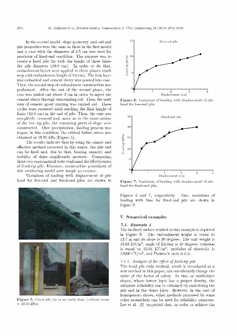
In the second model, slope geometry, and soil andpile properties were the same as those in the �rst modeland a case with the diameter of 5.5 cm was used forprovision of �xed-end condition. The purpose was tocreate a �xed pile tip with the height of three timesthe pile diameter (10.8 cm). In order to do that,embankment layers were applied in three phases (eachstep with embankment height of 3.6 cm). The �rst layerwas embanked and cement slurry was poured into case.Then, the second step of embankment construction wasperformed. After the end of the second phase, thecase was pulled out about 3 cm in order to inject thecement slurry through surrounding soil. Then, the nextstep of cement grout purring was carried out. Thesecycles were repeated until reaching the �nal height of�xity (10.8 cm) in the end of pile. Then, the case wascompletely removed and, same as in the constructionof the free tip pile, the remaining parts of slope wereconstructed. After precipitation, loading process wasbegan; in this condition, the critical failure stress wasobtained at 19.85 kPa (Figure 5).
The results indicate that by using the simple ande�ective method proposed in this paper, the pile endcan be �xed and, due to that, bearing capacity andstability of slope signi�cantly increase. Comparingthese two experimental tests con�rmed the e�ectivenessof �xed-tip pile. Moreover, construction procedures ofthis reinforcing model were simple to execute.
Variations of loading with displacement of pilehead for free-end and �xed-end piles are shown in
Figure 5. Fixed pile tip in an earth slope (critical stress= 19.85 kPa).
Figure 6. Variations of loading with displacement of pilehead for free-end pile.
Figure 7. Variations of loading with displacement of pilehead for �xed-end pile.
Figures 6 and 7, respectively. Also, variations ofloading with time for �xed-end pile are shown inFigure 8.
7. Numerical examples
7.1. Example 1The inclined surface studied in this example is depictedin Figure 9. The embankment height is equal to13.7 m and its slope is 30 degrees. The unit weight is19.63 kN/m3, angle of friction is 10 degrees, cohesionis equal to 23.94 kN/m2, modulus of elasticity is12000 kN/m2, and Poisson's ratio is 0.3.
7.1.1. Analysis of the e�ect of �xed-tip pileThe �xed pile ends method, which is introduced as anew method in this paper, can considerably change thevalue of the factor of safety. In two- or multi-layerslopes, whose lowest layer has a proper density, theadequate reliability can be obtained by embedding thepile end in the dense layer. However, in the case ofhomogenous slopes, other methods proposed by someother researchers can be used for reliability purposes.Lee et al. [42] suggested that, in order to achieve the

M. Hajiazizi et al./Scientia Iranica, Transactions A: Civil Engineering 25 (2018) 2550{2560 2555
Figure 8. Variations of loading with time for �xed-endpile.
Figure 9. Slope geometry in Example 1 and pilereliability length (Le) under critical slip surface.
reliability length (Le), the pile should be embedded inthe layer below the critical slip surface to a depth equalto H (distance between the critical failure surface andthe ground surface).
Kourkoulis et al. [14] believed that the pile reli-ability length (Le) could be 5D at most. Reese andVan [30] also indicated that the e�ective zone on eachpile beneath the critical slip surface did not exceed 5D.
In Figure 10, the critical slip surface for LEand SSR methods is shown. Figure 11 shows thecomparison of the results of the SSR method used forfree-end and �xed-end piles with a length of L = 1:5H.As seen in this �gure, �xing pile end has a signi�cante�ect on the growth of the factor of safety. A �xed pileend can increase the value of the factor of safety up to55%.
Figure 12 shows the comparison between theresults obtained by the SSR method for a row of pileswith a length of 1:5H and the results obtained fora row of free-end piles with a length of 2H in [25].As seen in this �gure, in spite of the short length ofthe pile, �xing the pile end has led to a considerableincrease in the value of factor of safety. Hence, bydiminishing the pile length and adding to the factor
Figure 10. Critical slip surface in LE method (yellowline) and SSR method (red line).
Figure 11. Comparison of the results of the SSR methodfor �xed-end and free-end for L = 1:5H.
Figure 12. Comparison of SSR method for �xed-end pilecondition with a length of 1:5H and reference [25] with alength of 2H.

2556 M. Hajiazizi et al./Scientia Iranica, Transactions A: Civil Engineering 25 (2018) 2550{2560
Table 1. Variations of pile reliability length and factor ofsafety for free-tip and �xed-tip.
Length ofpile(L)
FoS forfree-tip
FoS for�xed-tip
Percentageof change
H + 1D 1.07 1.69 58%H + 2D 1.08 1.68 55%H + 3D 1.09 1.69 55%H + 4D 1.1 1.7 54%H + 5D 1.11 1.7 54%
of safety, one of the main objectives of stabilization,i.e., cost reduction, is achieved. As seen in Figure 12,the maximum factor of safety belongs to the piles thatare installed in the middle of the slope. In Figure 12,which shows that the highest factor of safety belongs toxr = 0:5, variations of the reliability length (Le) belowthe critical slip surface are examined in proportion tothe factor of safety values. At each phase, the pilereliability length (Le) is increased by 1 � D. Table 1presents the variations of pile reliability length andfactor of safety.
As seen in Table 1, in the case of a �xed-endpile, increase in Le does not signi�cantly contributeto the increase in the factor of safety value. Due toimplementation reasons, it is necessary to have a pilereliability length that makes it possible to embed thepile in a depth two times the pile diameter in the layerbelow the critical slip surface to ensure that the slipband will be above reliability length of the end of pile.
7.1.2. Determining the most e�ective location for pileinstallation
The most e�ective location for pile installation is theplace that not only gives the required factor of safety,but also uses the minimum pile length. As it wasdescribed, the factor of safety in a homogenous soilcan be signi�cantly increased by �xing the pile endand reducing its length. Although the process of �xingpile end is time-consuming and requires precision, theresulting signi�cant increase in factor of safety andreduction in stabilization costs are the reasons thatjustify it. As seen in Figures 13 and 14, a horizontalplane can give the required factor of safety. Thepoint that the plane collides with the curve gives thecoordinates of di�erent pile lengths and locations. Theplace with the shortest pile length is the most e�ectivefor pile installation.
7.2. Example 2The three-layer earth slope studied in this exampleis depicted in Figure 15. The strength parametersof the third layer are larger than those of the othertwo layers. The slope height is 10 m and its angle is34 degrees. The physical characteristics of the layersare presented in Table 2. The �gures of numericalanalyses using SLOPW and FDM programs are shown
Figure 13. Three-dimensional diagram of free-end pilelength (L), pile location (x=r), and Factor of Safety (FoS)in Example 1.
Figure 14. Three-dimensional diagram of �xed-end pilelength (L), pile location (x=r), and Factor of Safety (FoS)in Example 1.
Figure 15. Three-layer earth slope geometry inExample 2.
in Figure 16. The minimum factors of safety for LEand SSR methods are calculated at 0.88 and 0.75,respectively.
7.2.1. Analysis of the e�ect of �xed pile tipIn this example, the third layer, which lies at thebottom of the pile, has the largest strength parameters.Figure 17 shows the results of modeling a pile for

M. Hajiazizi et al./Scientia Iranica, Transactions A: Civil Engineering 25 (2018) 2550{2560 2557
Table 2. Shear strength parameters of earth slope in Example 2.
Layerno.
Cohesion(kPa)
Friction angle(degree)
Unit weight(kN/m3)
Poisson'sratio
Elasticity modulus(kN/m2)
Layer 1 29.4 12 18.8 0.3 12000Layer 2 9.8 5 18.8 0.3 12000Layer 3 29.4 40 18.8 0.3 12000
Figure 16. Numerical analysis for Example 2: (a)SLOPEW, and (b) FDM softwares.
Figure 17. Comparison of LE and SSR methods fordi�erent locations and L = 1:5H in free-end and �xed-endconditions.
di�erent locations (0:1 � x=r � 0:8) and L = 1:5Hin free-end and �xed-end conditions.
As seen in Figure 17, �xing the pile end does not
Figure 18. Variations of pile reliability length (Le = �D)and FoS for the �xed-end and free-end piles.
leave a signi�cant e�ect on the value of factor of safety.The reason is that emplacing the pile end into a layerwith large strength parameters is the same as �xing thepile end. As seen in Figure 17, at x
r = 0:1, the resultsobtained for �xed-end pile do not very well comply withthe results of the free-end pile. The reason is that thelength required for emplacing the pile end into the thirdlayer is not achieved.
Figure 17 indicates that the largest factor of safetybelongs to x
r = 0:4. Hence, the variations of reliabilitylength (Le) are studied based on the factor of safetyof x
r = 0:4. Results of the variations of reliabilitylength (Le) are depicted in Figure 18. As seen in this�gure, in the case of the �xed-end pile, increase in thereliability length does not have a signi�cant e�ect onthe increase in the factor of safety. However, in the caseof the free-end pile, increase in the pile length leads tothe growth of safety factor. The maximum factor ofsafety is also achieved with L = H + 4D and withlength values higher than H + 4D, the factor of safetyremains unchanged. The increase in the factor of safetyis a result of the collision between pile end and thedense layer. A comparison between Figures 15 and 16indicates that to achieve a safety factor of 1.2 for a freepile tip, it is necessary to choose a pile with a length5D longer than the �xed pile tip. If the pile diameter isconsidered 1 meter, the volume of reinforced concretewill be increased by about 4 cubic meters. Given thatimplementation of concrete per cubic meter costs 20dollars, 80 extra dollars will be needed for each pile.

2558 M. Hajiazizi et al./Scientia Iranica, Transactions A: Civil Engineering 25 (2018) 2550{2560
Thus, 10 piles in a row will cause 800 dollars extracosts.
7.2.2. Determining the most e�ective and economicallocation for pile installation
As it was explained earlier, if the pile end is embed-ded in a strong layer, �xing the pile end will notsigni�cantly increase the factor of safety (except forthe pile end that is �xed in the vicinity of slopetoe). According to Figure 17, the safety factor forxr = 0:4 is equal to 1.67. Figures 19 and 20 showthe three-dimensional diagram of pile length (L), pilelocation (x=r), and factor of safety for free-end and�xed-end piles, respectively. In order to �nd the moste�ective location for pile installation, the horizontalplane for the factor of safety of interest should bemapped. The most e�ective location is the one thatrequires the shortest pile length. In fact, the moste�ective location not only yields the required factor
Figure 19. Three-dimensional diagram of pile length (L),pile location (x=r), and Factor of Safety (FoS) for free-endpile.
Figure 20. Three-dimensional diagram of pile length (L),pile location (x=r), and Factor of Safety (FoS) for�xed-end pile.
of safety, but also provides for the determination ofthe shortest pile length and reduction in stabilizationcosts.
8. Conclusion
In this paper, the minimum stabilization pile lengthwas achieved by a new proper method. Fixing piletip was a method that helped to reduce stabilizationcosts. Then, the most e�ective location that requiredthe shortest length was found by mapping the three-dimensional diagram of pile length, pile location, andfactor of safety. In order to obtain the maximum factorof safety for a row of free-end piles in homogenousslopes, the piles should be placed near slope crown orin the middle of the slope. If the piles are installedin inappropriate location with inadequate length, thefactor of safety decreases, instead of increasing.
Fixing pile tips in homogenous slopes could in-crease factor of safety by up to 55%. As a result,pile length and stabilization costs would be reduced.It should be mentioned that �xing pile tips should bedone with adequate care. If the end of a pile in a non-homogeneous slope is emplaced into a dense layer, therequired reliability length will be achieved. In suchcases, �xing pile tip will not signi�cantly increase thefactor of safety. However, if the pile tip is embeddedinto soft layer, �xing pile tips can increase the safetyfactor by up to 55%.
References
1. Hajiazizi, M., Kilanehei, P., and Kilanehei, F. \A newmethod for three dimensional stability analysis of earthslopes", Scientia Iranica, 25(1), pp. 129-139 (2018).
2. Ghanbari, E. and Hamidi, A. \Stability analysis ofdry sandy slopes adjacent to dynamic compactionprocess", Scientia Iranica, 24(1), pp. 82-95 (2017).
3. Zhang, G. and Wang, L. \Integrated analysis of acoupled mechanism for the failure processes of pile-reinforced slopes", Acta Geotechnica, 11(4), pp. 941-952 (2016).
4. Wang, L. and Zhang, G. \Progressive failure behaviorof pile-reinforced clay slopes under surface load con-ditions", Environmental Earth Sciences, 71(12), pp.5007-5016 (2014).
5. Xu, J. and Niu, F. \Safety factor calculation ofsoil slope reinforced with piles based on Hill's modeltheory", Environmental Earth Sciences, 71(8), pp.3423-3428 (2014).
6. Xiao, S. \A simpli�ed approach for stability analysisof slopes reinforced with one row of embedded stabi-lizing piles", Bulletin of Engineering Geology and theEnvironment, pp. 1-12 (2016).
7. Chen, C., Xia, Y., B, V.M. \Slope stability analysis bypolar slice method in rotational failure mechanism",Computers and Geotechnics, 81, pp. 188-194 (2017).

M. Hajiazizi et al./Scientia Iranica, Transactions A: Civil Engineering 25 (2018) 2550{2560 2559
8. Chen, L.T., Poulos, H.G., and Hull, T.S. \Model testson pile groups subjected to lateral soil movement",Soils and Foundation, 37(1), pp. 1-12 (1997).
9. Chen, C.Y. and Martin, G.R. \Soil-structure inter-action for landslide stabilizing piles", Computers andGeotechnics, 29(5), pp. 363-386 (2002).
10. Liang, R. and Zeng, S. \Numerical study of soil archingmechanism in drilled shafts for slope stabilization",Soils and Foundations, 42(2), pp. 83-92 (2002).
11. Verveckaite, N., Amsiejus, J., and Stragys, V. \Stress-strain analysis in the soil sample during laboratorytesting", J. of Civil Engineering and Management,13(1), pp. 63-70 (2007).
12. Kahyaoglu, M.R., Imancli, G., Ozturk, A.U., andKayalar, A.S. \Computational 3D �nite element anal-yses of model passive piles", Computational MaterialsScience, 46(1), pp. 193-202 (2009).
13. Kahyaoglu, M.R., Onal, O., Iman�cl�, G., Ozden, G.,and Kayalar, A.S. \Soil arching and load transfermechanism for slope stabilized with piles", J. of CivilEngineering and Management, 18(5), pp. 701-708(2012).
14. Kourkoulis, R., Gelagoti F., Anastasopoulos I., andGazetas, G. \Hybrid method for analysis and design ofslope stabilizing piles", J. of Geotechnical and Geoen-vironmental Engineering, 138(1), pp. 1-14 (2012).
15. De Beer, E.E. and Wallays, M. \Forces induced inpiles by unsymmetrical surcharges on the soil roundthe piles", Conf. on Soil Mechanics and FoundationEngineering, 1, Spanish Society for Soil Mechanics andFoundations, Madrid, Spain, pp. 325-332 (1972).
16. Ito, T. and Matsui, T. \Methods to estimate lateralforce acting on stabilizing piles", Soils and Founda-tions, 15(4), pp. 43-60 (1975).
17. Hassiotis, S., Chameau, J.L., and Gunaratne, M.\Design method for stabilization of slopes withpiles", Geotech. Geoenviron. Eng., 123(4), pp. 314-323(1997).
18. Chen, L.T., Poulos, H.G., and Hull, T.S. \Model testson pile groups subjected to lateral soil movement",Soils and Foundation, 37(1), pp. 1-12 (1997).
19. Poulos, H.G. \Design of reinforcing piles to increaseslope stability", Can Geotech J., 32(5) pp. 808-818(1995).
20. Tschebotario�, G.P., Foundations, Retaining andEarth Structures, McGraw Hill, New York (1973).
21. Fakhimi, A., Continuum Analysis 2-Dimensional-Theory and User's Manual, BHRC Publication, Iran(2001).
22. Poulos, H.G. and Chen, L.T. \Pile response due toexcavation induced lateral soil movement", Geotech.Geoenviron. Eng., 123(2), pp. 94-99 (1997).
23. Goh, A.T.C., The, C.I., and Wong, K.S. \Analysisof piles subjected to embankment induced lateral soilmovements", Geotech. Geoenviron. Eng., 123(4), pp.312-323 (1997).
24. Hajiazizi, M. and Mazaheri, A.R. \Use of line segmentsslip surface for optimized design of piles in stabiliza-tion of earth slopes", International Journal of CivilEngineering, Geotechnical Engineering, 13(1), pp. 14-27 (2015).
25. Li, X., Pei, X., Gutierrez, M., and He, S. \Optimal lo-cation of piles in slope stabilization by limit analysis",Acta Geotechnica, 7(3), pp. 253-259 (2012).
26. Hassiotis, S., Chameau, J.L. and Gunaratne, M.\Design method for stabilization of slopes with piles",Geotech. Geoenviron. Eng. ASCE, 123(4), pp. 314-323(1997).
27. Poulos, H.G. \Design of slope stabilizing piles", SlopeStability Engineering, N. Yagi, T. Yamagami, and J.C.Jiang, Eds., A. A. Balkema, Rotterdam, Netherlands(1999).
28. Reese, L.C., Wang, S.T., and Fouse, J.L. \Use ofdrilled shafts in stabilizing a slope", Proc., SpecialtyConf. on Stability and Performance of Slopes andEmbankments II (GSP 31), 2, ASCE, New York, pp.1318-1332 (1992).
29. Johari, A., Mousavi, S., and Hooshmand Nejad, A. \Aseismic slope stability probabilistic model on Bishop'smethod using analytical approach", Scientia Iranica,22(3), pp. 728-741 (2015).
30. Reese, L.C. and Van Impe, W.F. \Single piles and pilegroups under lateral loading", A. Balkema, Rotterdam,Netherlands (2001).
31. Poulos, H.G. \Analysis of piles in soil undergoinglateral movement", Soil Mech. Found. Div ASCE,99(5), pp. 391-406 (1973).
32. Ashour, M. and Ardalan, H. \Analysis of pile stabilizedslopes based on soil-pile interaction", Computers andGeotechnics, 39, pp. 85-97 (2012).
33. Won, J., You, K., Jeong, S., and Kim, S. \Couplede�ects in stability analysis of pile-slope systems",Computers and Geotechnics, 32, pp. 304-315 (2005).
34. Ausilio, E., Conte, E., and Dente, G. \Stabilityanalysis of slopes reinforced with piles", Computersand Geotechnics, 28, pp. 591-611 (2001).
35. Ebadi, M., Habibagahi, G., and Hataf, N. \E�ectof cement treatment on soil non-woven geotextileinterface", Scientia Iranica A, 22(1), pp. 69-80 (2015).
36. Yildiz, M. and Soganci, A.S. \Improvement of thestrength of soils which comprises granular pumice byinjection of cement under low pressure", J. ScientiaIranica A, 22(1), pp. 81-91 (2015).
37. Wei, W.B. \Three dimensional slope stability analysisand failure mechanism", Ph.D. Thesis, Hong KongPolytechnic University, Hong Kong (2008).
38. Wang, M.C., Wu, A.H., and Scheessele, D.J. \Stressand deformation in single piles due to lateral movementof surrounding soils", Behavior of Deep Foundations:ASTM Special Technical Publication, 670, RaymondLunggren, Ed., ASTM, West Conshohocken, PA, pp.578-591 (1979).

2560 M. Hajiazizi et al./Scientia Iranica, Transactions A: Civil Engineering 25 (2018) 2550{2560
39. Popescu, M.E. \Landslide control by means of a rowof piles", Slope Stability Engineering: Proc., Int. Conf.on Slope Stability, Thomas Telford, London, pp. 389-394 (1991).
40. Li, X., Pei, X., Gutierrez, M., and He, S. \Optimal lo-cation of piles in slope stabilization by limit analysis",Acta Geotechnica, 7, pp. 253-259 (2012).
41. Papadopolou, M.C. and Comodromos, E.M. \On theresponse prediction of horizontally loaded �xed-headpile groups in sands", Computers and Geotechnics, 37,pp. 930-941 (2010).
42. Lee, C.Y., Hull, T.S., and Poulos, H.G. \Simpli�edpile-slope stability analysis", Computers and Geotech-nics, 17, pp. 1-16 (1995).
Biographies
Mohammad Hajiazizi is Associate Professor ofGeotechnical Engineering at Razi University, Kerman-shah, Iran. He received his PhD degree in GeotechnicalEngineering from Shiraz University under the Supervi-
sion of Professors A. Ghahramani and Hataf and hisMSc degree in Geotechnical Engineering from TarbiatModarres University under the supervision of ProfessorA. Fakhimi. His current and main research interestsare soil improvement, slope stability, tunneling, andmeshless methods.
Mosoud Nasiri is PhD candidate in GeotechnicalEngineering at Razi University, Kermanshah, Iran. Hereceived his MSc degree in Geotechnical Engineeringfrom Razi University under the supervision of Dr. M.Hajiazizi.
Ahmad Reza Mazaheri is Assistant Professor ofGeotechnical Engineering at Ayatollah Borujerdi Uni-versity. He received his PhD degree in GeotechnicalEngineering from Razi University under the super-vision of Dr. M. Hajiazizi and his MSc degree inGeotechnical Engineering from Amirkabir University ofTechnology. His current and main research interests areslope stability and soil improvement.