the dofasco experimental steel house (d.e.s.h. #1)
TRANSCRIPT

Missouri University of Science and Technology Missouri University of Science and Technology
Scholars' Mine Scholars' Mine
International Specialty Conference on Cold-Formed Steel Structures
(1978) - 4th International Specialty Conference on Cold-Formed Steel Structures
Jun 1st, 12:00 AM
The Dofasco Experimental Steel House (D.E.S.H. #1) The Dofasco Experimental Steel House (D.E.S.H. #1)
Roderick W. Eastman
Andrew S. Zakrzewski
Follow this and additional works at: https://scholarsmine.mst.edu/isccss
Part of the Structural Engineering Commons
Recommended Citation Recommended Citation Eastman, Roderick W. and Zakrzewski, Andrew S., "The Dofasco Experimental Steel House (D.E.S.H. #1)" (1978). International Specialty Conference on Cold-Formed Steel Structures. 6. https://scholarsmine.mst.edu/isccss/4iccfss/4iccfss-session4/6
This Article - Conference proceedings is brought to you for free and open access by Scholars' Mine. It has been accepted for inclusion in International Specialty Conference on Cold-Formed Steel Structures by an authorized administrator of Scholars' Mine. This work is protected by U. S. Copyright Law. Unauthorized use including reproduction for redistribution requires the permission of the copyright holder. For more information, please contact [email protected].

THE DOFASCO EXPERZMENTAL STEEL HOUSE (D.E.S.H. 11)
by
SUMMARY
1 Roderick w. Eastman, P.Eng., B.Eng.
Andrews. Zakrzewski, P.Eng., M.Sc. 2
The erection of an experimental steel house incorporating a
large number of cold rolled steel products is described.
Many of the light qauqe steel structural components are
currently under development and this house serves as a
"field laboratory" in which their performance can be
evaluated. Particular reference is made to results obtained,
to date, from tests on the light gauge steel basement wall
panels, residential steel floor joists, and load bearing
"thermal" steel studs.
INTRODUCTZON
Dofasco has now been involved in the development of steel
components for housing for over eight years. During this
period, we have developed two panelized housing systems,
several panelized steel basement models, as well as framing
and floor deck components.
1Project Engineer, Product Development Engineering, Dominion Foundries and Steel, Limited, Hamilton, Ontario.
2Manager, Flat Rolled Engineering Group, Product Development Engineering, Dominion Foundries and Steel, Limited, Hamilton, Ontario.
989

990 FOURTH SPECIALTY CONFERENCE
Some of our earlier work was reported during the two previous
International Specialty Conferences on Cold-Formed Steel
Structures.
In 1974, we obtained approval from our management for the
construction of a Dofasco F.xperimentai Steel House, to
be located in Dofasco's Recreation Park near Hamilton,
Ontario.
The detached split entry house with an attached garage was
completed in the Spring of 1977.
The Experimental Bouse was to fulfill several objectives:
(1) It would allow us to test the erection and performance
of several newly developed steel components.
(2) It should prove that a rather complex house can contain
an extensive amount of steel components, and yet, look
like any other well designed conventionally built house.
(3) It would serve as a "field laboratory" to test the
behaviour and performance of steel, as well as non-steel
systems, over a long period of time, under "real life"
conditions. It is hoped that the information gathered

EXPERIMENTAL STEEL HOUSE
over a period of several years will help the steel
industry, and builders, to assess the merits of steel,
and optimize the design of steel components.
THE USE OF STEEL
The house contains 9.5 tons (8.6 metric tons) of steel
991
components and fitments (Figure 1). Some of them have already
been commercialized, but many are of an experimental nature
and will be tested and proven in the house. These include
the new, improved steel basement, floor decks containing our
newly developed I-shaped roll formed joists, a roll formed
center beam, as well as complete steel framing for the
upper walls.
Steel was also used extensively as a cladding material. Roof
tiles made in the form of steel panels replaced conventional
asphalt shingles. The soffit, rainware, siding and external
doors were all made from steel.
THE ERECTION
One of the purposes of the Experimental Steel House was to
check the erection procedures.
We wanted the challenge of a relatively complex design.

992 FOURTH SPECIALTY CONFERENCE
Therefore, we selected a split entry house with a raised
base~ent, direct exit from the lower level to the back yard,
and an attached garage.
(1) The Foundation
The construction began with the usual excavation, which
was sized to be approximately 2' larger than the finished
basement. After the installation of service connections,
a 5" to 6" (12.70 em to 15.24 em) thick layer of 3/4"
(1.9 em) clear gravel was dumped into the excavated
area, then raked and levelled. This "gravel pad"
performs two functions. It becomes a water collection
and draining system, and supports the basement footing.
A recent study (Appendix 1, Reference 5) indicates that
the gravel pad constitutes a better drainage system than
the conventional perimeter weeping ti·le. In our
Experimental House, the water entering the gravel bed
is drained to the lower sump area and pumped from there
by means of a sump pump to a drainage ditch at the
roadside.
The raised basement walls were backfilled 4' (1.22 m),
except around the sliding door which exits into the rear
yard. In order to avoid frost damage, a 4' (1.22 m) deep

EXPERIMENTAL STEEL HOUSE 993
trench was excavated below the . sliding door and filled
with gravel.
A special steel channel, placed directly on the gravel,
formed the perimeter house footing. In addition to
galvanizing, the .107" (2.77 mm) thick section was
further protected against corrosion by a .010" (.25 mm)
coal tar epoxy coating. This steel footing performs
several functions:
(a) It supports the whole house.
(b) It provides resistance against uplift forces.
(c) Tabs formed up in the base of the footing restrict
the deflection of the bottom edge of the wall panels,
which are subjected to backfill pressure (Figure 2).
(d) Openings left after forming of tabs allow any water
entering the channel like footing, to drain into
the gravel bed.
(e) The inside f lange and lip of the footing act as a
form and screed fo r the concrete floor.

994 FOURTH SPECIALTY CONFERENCE
(2) Lower Level Walls and Center Beam
The lower level walls forming the raised basement consisted
of interlocking steel panels. The panels were 24" (60.9~ em)
wide, 4" (10.16 em) deep, and 8' (2.44 m) high. They
were made from .03~" (.91 mm), G-90 galvanized steel
and were coated for additional protection and appearance
above ground with an 8 mil (.20 mm) thick plastisol
paint.
The panel ribs were louvered to reduce the heat flow
through the walls (Figure 2), and were provided with
service holes for electrical wiring. A male-female
sealing groove was formed along the whole length of
the panel rib, in order to prevent ~rater penetration
into the wall.
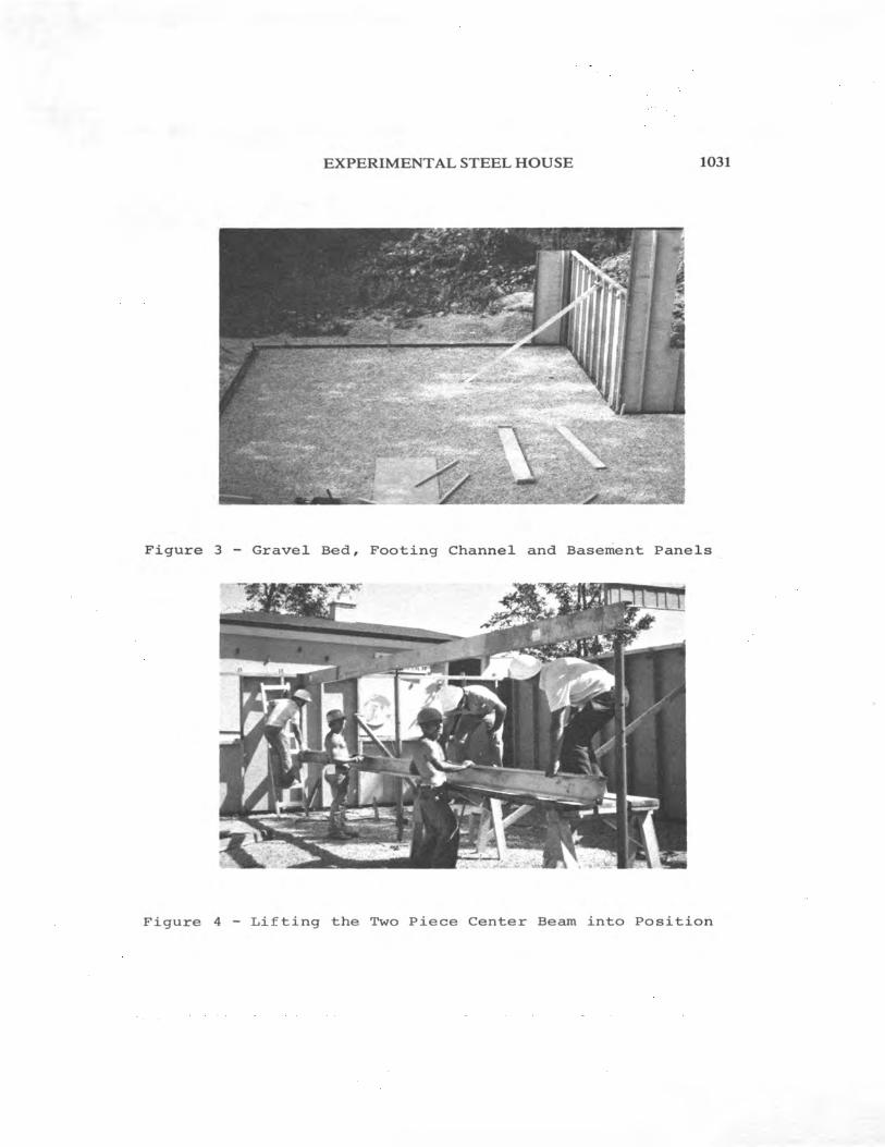
During the erection, the wall panels were placed into
the footing channel and attached to it by means of
nuts and bolts. Every six panels erected ~rere secured
on top with nuts and bolts to a 12' (3.~6 m) long top
channel, made from .060" (1.52 mm) thick galvanized
steel. At the same time, joist hangers were attached
to the wall panels and the top channel. The walls were
then temporarily braced (Figure 3).

EXPERIMENTAL STEEL HOUSE
The basement panels were also used for the attached
garage. In this case, however, the pan~ls were 13'
(3.96 m) high reaching from the footings, located
4' (1.22 m) below grade, to the roof eave.
995
The joist span in a house is usually reduced by provision
of either a center beam or a load bearing center wall.
Both systems were used in our Experimental Steel House.
The center beam was supported on conventional teleposts
which were placed on 1/4" (6.35 mm) thick steel footing
plates, resting directly on the gravel bed. The center
beam consisted of two cold rolled steel c-sections,
8-1/2" (21.59 em) deep, and .105" (2.67 mm) thick.
Placing each 26' (7.93 m) long c-section separately
on teleposts made lifting easy. The c-sections were
placed back to back, and bolted to the teleposts and
to each other (Figure 4).
The load bearing center wall was framed in the flat from
3-1/2" (8.89 em) deep steel studs 24" (60.96 em) on center,
and from channel shaped top and bottom plates. All of
the above components were made from .036" (.91 mm) thick
G-90 galvanized steel.

996 FOURTH SPECIALTY CONFERENCE
After assembly, the wall frame was raised and placed on
top of a 6" (15.24 em) wide, 1/4" (6.35 mm) thick steel
footing plate.
(3) Upper Level
The steel framing for the upper floor walls was assembled
in 12' (3.66 m) long sections, in the flat, on the main
floor deck. The frames were then sheathed on one side
with 3/8" (9.5 mm) plywood, raised and braced in position
(Figure 5). The framing elements consisted of 1-1/2" x
3-1/2" x .036" (3.81 em x 8.89 em x .91 mm) lipped "C"
studs, and top and bottom channels. Two rows of slots,
prepunched in the stud webs (Figure 1), reduce their
thermal conductivity. Prepunched tabs, provided in the
top and bottom channels at 24" (60.96 em) intervals,
assisted in speeding up the assembly of studs. They
positively located and held the studs, so that no
fasteners were required until the sheathing was attached
to the frame.
One inch diameter holes with a curled back edge were
provided in studs for electrical wiring.
Brackets, factory attached to the top plate, were provided
for location and securing of roof trusses. The brackets
facilitated placing of roof trusses and ensured that the

EXPERIMENTAL STEEL HOUSE
trusses were located directly above the load bearing·
studs.
997
Steel was also used as a roof sheathing material. We
selected panels formed from .020" (.51 mm) thick steel
into the shape of tiles. The roof trusses were covered
with a single layer of building paper and strapped on
16" (40.64 em) centers, with 2" x 2" (5.08 em x 5.08 em)
wood purlins, to which the steel tiles were nailed.
In this system, the conventional plywood sheathing was
eliminated (Figure 6).
The roof tiles ~ere galvanized and covered with a natural
coloured stone aggregate, embedded in an asphaltic coating.
This kind of steel tile has been used extensively in
several countries, but is quite new in Canada. Its
appearance compares with that of expensive clay tiles.
(4) Interior and Exterior Finishes
The interior non-load bearing walls were framed using
the typical non-load bearing steel studs, 16" (40.64 em)
on center. R-12 (RSI 2.1) fiberglas friction batts were
used to insulate both the lower and upper floor walls.
The attic was insulated with R-20 (RSI 3.5) fiberglas
batts.

998 FOURTH SPECIALTY CONFERENCE
Ha1f inch (1.27 em) drywa11 was attached with se1f drilling
screws to a11 the wa11 studs, and the stee1 joists, where
a finished cei1ing was required in the basement.
On the outside, the exposed fr~nt portion of the basement
was clad with brick pane1s, consisting of 1/2" (1.27 em)
thick bricks, 1aminated to 1/2" (1.27 em) thick asphalt
board. The boards were attached to the steel basement
pane1s with self dri11ing screws and the seams between
the bricks were then grouted to look like masonry.
The upper f1oor walls were externally sheathed with
commercia1ly available stee1 siding. Steel soffit and
steel rainware completed the exterior of the house
(Figure 7).
THE TEST PROGRAM
The materials and components used in the house structure
have to satisfy a vast range of conditions. They must withstand
complex and variab1e loading conditions, such as scil pressure,
wind loads, vertical loads including snow load, dynamic loads
caused by human beings, equipment, etc. The outer envelope
of the house may be subjected to external water penetration,
and condensation caused by the migrating water vapour.
EXPERIMENTAL STEEL HOUSE 999
The components must withstand considerable temperature
variations, satisfy stringent heat transfer limitations,
must not warp or deflect excessively, or deteriorate in any .
appreciable way over a period of 50 or even 100 years. They
must satisfy the human comfort conditions which encompass
limitations on vibrations, transfer of sound, temperature
and humidity variations, etc.
The use of steel, particularly light gauge sheet steel, has,
so far, been very limited in housing applications. Consequently,
the knowledge of its performance under the complex conditions
is also very limited.
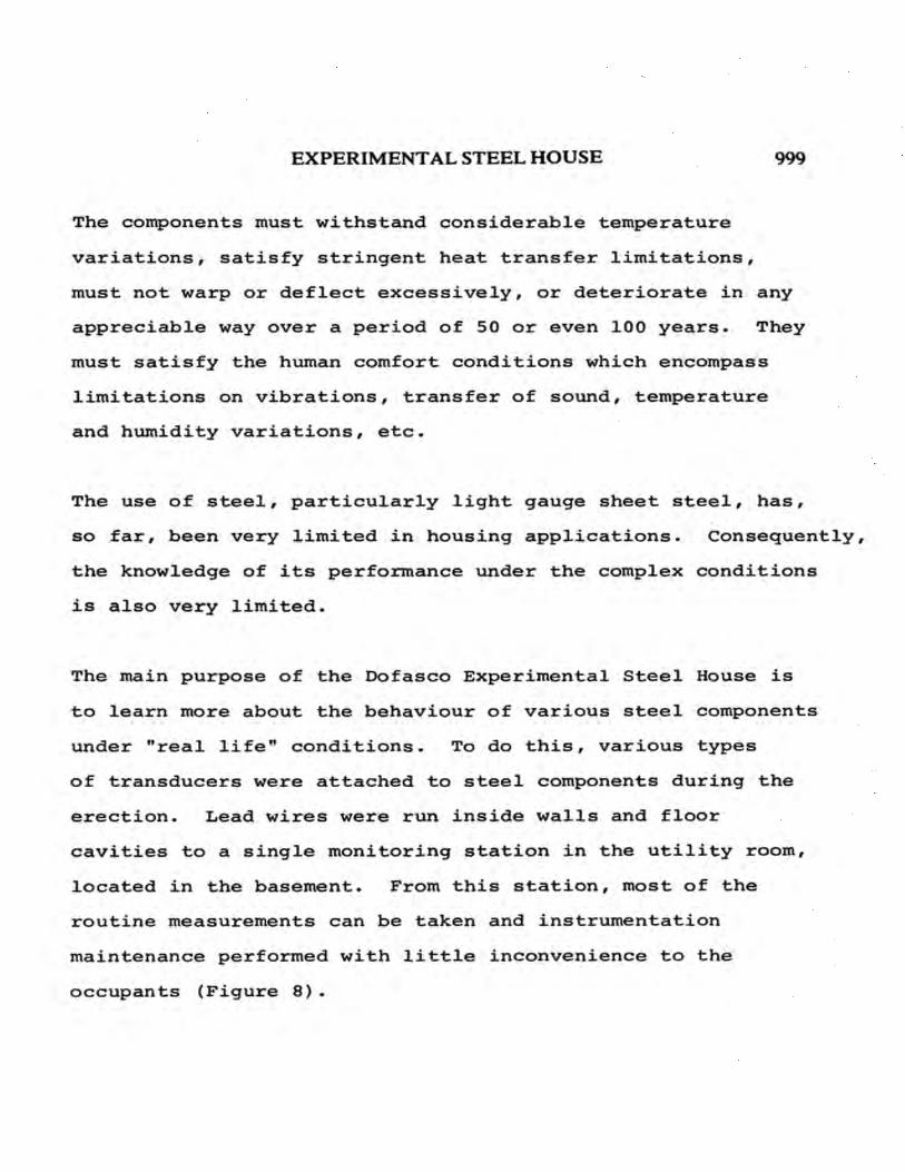
The main purpose of the Dofasco Experimental Steel House is
to learn more about the behaviour of various steel components
under 11 real life 11 conditions. To do this, various types
of transducers were attached to steel components during the
erection. Lead wires were run inside walls and floor
cavities to a single monitoring station in the utility room,
located in the basement. From this station, most of the
routine measurements can be taken and instrumentation
maintenance performed with little inconvenience to the
occupants (Figure 8).

1000 FOURTH SPECIALTY CONFERENCE
The tests were not restricted to measuring the behaviour of
steel components only. They include the behaviour of
systems affecting the steel components, such as the gravel
bed, or the backfill soil, etc.
(1) Drainage
The steel footings supporting the basement walls were
placed on top of a layer of gravel. While this gravel
bed appears to be an excellent means of gathering and
draining ground water, we also provided a conventional
plastic weeping tile, placed adjacent to the footing.
The gravel bed and weeping tile were drained to separate
sump boxes, each of which was equipped with a sump pump
and a flow meter. By using a valve, the flow from the
weeping tile can be shut off. This enables us to
compare the effectiveness of the two drainage systems.
During backfilling, a layer of sand was placed on top
of the gravel, outside of the foundation, along one
side of the house. If, after some years of seYvice,
this area was excavated and the amount of sand in the
gravel determined, some assessment could be made of the
degree of penetration (danger of clogging).

EXPERIMENTAL STEEL HOUSE
In order to obtain more information about the soil,
the variations in the water level in the ground and
gravel must be known. To do this, we placed one
piezometer under the house and another in the ground
c1ose to the house.
1001
A11 the above tests, while seemingly unrelated to steel,
are of importance in the assessment of the "dry system"
of footings, i.e. a system not using cement poured on-site.
(2) Soil Pressure
The lateral pressure exerted by the soil against the
basement walls depends upon the type of soil, methods
of backfilling, and the amount of moisture in the soil.
The amount and distribution of pressure greatly affect
the design of steel basement walls.
To monitor these conditions, we installed several
earth pressure cells, placed against the outside of the
basement panels at the footing level. The pressure cells
will provide us with information on how the pressure
changes with seasons, and how it is affected by the
settlement and consolidation of the backfill material.

1002 FOURTH SPECIALTY CONFERENCE
(3) Foundation Wall
(a) Movement
Since the steel basement panels are considerably
lighter and much more flexible than concrete walls,
the soil pressure will displace the basement panels
to a larger degree. This displacement is being
periodically determined by measuring the distance
from twelve points on one section of the basement
wall to a stationary reference point.
(b) Stresses
To determine load levels, changes in loads, and to
uncover possible highly loaded areas, strain gauges
were attached to various structural steel components
throughout the house at the component's critical
points. Stresses are being recorded at regular
intervals.
(c) Corrosion Protection
Two different corrosion protection systems for the
steel panels below ground have been installed and
their performance is being monitored constantly.

EXPERIMENTAL STEEL HOUSE 1003
(4) Heat Transfer
Thermal performance will be assessed by two methods:
(a) Infra-red photography, or "thermovision" inspection
of all exterior walls is a good indication of the
quality of the thermal design and insulation
practices.
(b) Numerous thermocouples were attached to exterior
walls at various material interfaces. These spot
temperatures allow us to plot temperature profiles
through the cross section of the walls. From this
information the thermal performance and heat loss,
both above and below ground, can be determined.
One of the major sources of heat loss is air infiltration.
We have carried out an air leakage test to determine the
tightness of this steel house, for comparison with that
of conventional houses.
(5) Condensation
Excessive condensation inside wall or roof cavities is
one of the greatest sources of trouble in houses.

1004 FOURTH SPECIALTY CONFERENCE
We installed several humidity transducers inside the
wall and roof cavities, and we expect the data obtained
from them, as well as from thermocouples, will help us
determine condensation potentials of steel components.
A small portion of the interior sheathing of a basement
wall was made removable. This enables us to check the
condition of insulation and visually check for signs of
condensation and corrosion on the inside of the steel
basement wall panel.
(6) Floor Deflection
Five floor deck test sections, utilizing three different
types of joists, were incorporated in the upper level
floor deck. The test decks were subjected to static
and dynamic loads. Deflections, frequency and damping
rates were determined.
(7) Acoustics
We plan to carry out acoustic tests, with the help of
National Research Council personnel, in order to
determine sound transmission and impact isolation
coefficients.
EXPERIMENTAL STEEL HOUSE 1005
DISCUSSION AND RESULTS
Since the house has been completed for less than one year,
we will confine the discussion to areas where sufficient
test data has been accumulated.
(1) Floor Joists
(a) Static Performance
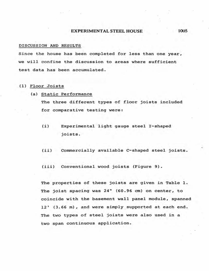
The three different types of floor joists included
for comparative testing were:
(i) Experimental light gauge steel I-shaped
joists.
(ii) Commercially available C-shaped steel joists.
(iii) Conventional wood joists (Figure 9).
The properties of these joists are given in Table 1.
The joist spacing was 24" (60.96 em) on center, to
coincide with the basement wall panel module, spanned
12' (3.66 m), and were simply supported at each end.
The two types of steel joists were also used in a
two span continuous application.

1006 FOURTH SPECIALTY CONFERENCE
The 3/4" (1.9 em) tongue and groove plywood subfloor
sheathing was attached to the steel joists with
adhesive and self-drilling screws. The adhesive
acts as a cushion to reduce the tendency for squeaks,
which can develop between the steel and wood elements.
It also provides a continuous shear connection into
the subfloor material. By utilizing the composite
action of the floor sheathing and designing a stressed
skin floor deck, longer joist spans can be achieved.
In one area of the house, the subfloor sheathing was
attached to the steel joists using pneumatically
driven, ring shanked T-nails. This method did prove
faster than generally used self-drilling screws, and
our laboratory tests have shown that when used in
conjunction with adhesives, holding power equivalent
to that of self-drilling screws can be easily attained.
Each deck test section consisted of three adjacent
joists, with deflection measurements taken off the
central joist. A special telescoping device was
constructed, incorporating a dial indicator for
reading the actual deflections. This device was
located between the floor deck and the ceiling above.

EXPERIMENTAL STEEL HOUSE 1007
Load was provided by successive layers of concrete
blocks spread uniformly over the test area (Figure 10).
The maximum loading was approximately 100 lb. per foot
(140 kg/m), or 1.25 times design load (40 psf- 195
kg/sq m).
The two steel joists and the wood joists, on 12'
(3.66 m) simply supported spans, produced essentially
identical deflections over the load range tested. The
actual deflections were only 53% of the allowable
deck deflection of span (inches)/360 at design
load (Figure 11).
Thus, from a static deflection standpoint, both the
light gauge steel I-shaped joist and the c-shaped
steel joist, 7-1/4" (18.4 em) high, are equivalent
to nominal 2" x 10" [actual dimensions 1-1/2" x
9-1/4" (3.81 em x 23.50 em)] wood joists, although
they weigh approximately 75% and 58% less, respectively.
This weight difference makes the steel joists more
easily handled, particularly in long lengths. Also,
since steel joists are cut to length, installation
times can he significantly reduced.
Laboratory tests on similar deck sections also show
that the deflection performance of these two steel

1008 FOURTH SPECIALTY CONFERENCE
joists is identical. At design load, the measured
deflection was approximately 62% of allowable, and
that for wood was slightly greater at 80% of allowable.
The smaller deflections recorded in the actual house
can be mainly attributed to the addition of adhesives
and the continuity of the test sections in the
transverse direction. The larger difference between
laboratory and field deflections for wood is perhaps
due to a better shear transfer link, via the adhesive,
for wood to wood connections, as opposed to wood to
steel.
The equivalency of the I and C-shaped joists was
further substantiated by the two span continuous
joist test results.
(b) Dynamic Performance
The same five deck test sections previously tested
for static deflection have also been evaluated for
comparative dynamic performance. The prime objective
was to determine and compare the natural frequencies
and damping rates of the various types of joists,
with and without a nominal uniformly distributed load.

EXPERIMENTAL STEEL HOUSE 1009
The natural frequencies of vibration were determined by
providing a steady state, sinusoidal forcing vibration,
with variable frequency, at the mid span of the central
joist in the deck section. An electro-magnetic shaker
was used to provide this input. The displacement probe
of a vibration analyser was located next to the shaker.
As the frequency was slowly increased, maximum amplitude
readings were taken and plotted in Figure 12.
The fundamental natural frequencies of the two light
gauge steel joists were approximately the same, i.e.
20 Hz, while that for the wood joist was approximately
18% higher (Table 3).
The human body is sensitive to frequencies and amplitudes
of vibration (Appendix 1, Reference 11). The lower the
frequency, the greater can be the amplitudes before the
vibrations are sensed. Therefore, the lower the natural
frequency of the floor system, the more acceptable it
becomes.
Whether the joist spans were 12' (3.66 m) simply supported
or continuous over a center support, did not affect natural
frequencies significantly. However, the addition of a

1010 FOURTH SPECIALTY CONFERENCE
10 psf (49 kg/m2 ) uniform load reduced the fundamental
frequencies of all joists to 14 Hz.
Damping rates for all deck test sections were calculated
from the recorded response to the impact of a person
dropping from the balls of his feet onto his heals
(heal drop test). In most cases, rates less than 5%
of critical were calculated. Thus, these floors can
be considered undamped. Surprisingly, no significant
difference in damping could be detected between the
wood and steel joists.
The addition of the uniform load of 10 psf (49 kg/m2 )
did not affect the damping rates significantly, nor
did the addition of heavy carpeting with a foam underpad.
The carpet, by virtue of its cushioning properties,
reduces the energy received by the floor from an impact,
and the amplitude of the resulting vibration. This is
often sufficient to lower the sensation to a less
perceivable and, therefore, less annoying level.
(2) Foundation Walls
In Canadian housing, soil pressures are generally calculated
based on a triangular pressure distribution equivalent to

EXPERIMENTAL STEEL HOUSE · 1011
half hydrostatic pressure (Appendix 1, Reference 5 and
Figure 13). Actual field measurements (Appendix 1,
Reference 10) have shown that in certain soil conditions,
pressures can be, in fact, much higher.
The soil at the site of the Experimental Steel House was
hard to very stiff, silty clay with cohesive oxidized seams.
The general area was low and poorly drained. These
characteristics are indicative of high soil pressures.
Consequently, the light gauge steel foundation wall panel
was designed with a fairly high safety factor.
Because of the rigidity of conventional concrete foundations,
backfilling procedures, which were developed, are somewhat
crude. Little or no particular attention is paid to the
placing of large, cohesive lumps or rocks. The bulldozer
travels back and forth over the freshly backfilled area,
compacting the surface layer. This results in high lateral
pressures and a distribution considerably different to
triangular.
The foundation walls of the Experimental Steel House were
made from light gauge steel interlocking panels, as described
earlier. The interlocking joint forms the basic structural
support for both axial loads and bending loads due to backfill

1012 FOURTH SPECIALTY CONFERENCE
soil pressures. This wall has considerably lower mass and
stiffness than its concrete counterpart and, therefore, the
pressures exerted by the backfill soil could conceivably
result in large lateral wall movement.
For the above reasons, three different parameters are being
measured in order to evaluate the performance of the
foundation walls. These are:
(a) Lateral displacement.
(b) Backfill soil pressure.
(c) Foundation panel stresses.
(a) Lateral Displacement
During construction, at the bottom of the excavation, a
6" (15.24 em) diameter hole was augered to bedrock and
filled with concrete. This formed a stationary reference
point, relative to which lateral displacements of the
foundation wall could be measured. Twelve locations
on one section of the foundation wall were selected,
and the measurements taken with a linear measuring
geotechnical instrument. Lateral displacements were

EXPERIMENTAL STEEL HOUSE
calculated from a vector analysis, based on the
assumption of one directional movement only.
1013
The connection between the top of the foundation wall
panel and the main floor deck was somewhat flexible,
and permitted some lateral movement. A maximum
displacement of 1/4" (6.35 mm) was recorded near the
top of the wall, as well as at mid height (Figure 14).
While these displacements are greater than those
encountered with concrete foundations, the resulting
stresses are still relatively low.
For the twelve months since erection, the displacements
have been increasing. As the soil consolidates,
displacements at the top of the wall should increase
less rapidly, or decrease as those nearer the bottom
continue to increase.
(b) Backfill Soil Pressures
Four Terra-Technology, pneumatic earth pressure cells
were installed at various locations outside the
foundation wall, at the footing level. One of these
was located inside the garage which was backfilled,
and a 3" (7.62 em) concrete floor poured on top.
1014 FOURTH SPECIALTY CONFERENCE
Prior to installation, the cells were calibrated in
the laboratory for variations in temperature, and also
on site, to account for the flexibility of the
foundation panel.
Initially, all but one of the backfill pressure
measurements were in excess of the accepted design
value [i.e. half hydrostatic pressure = .785 psi
(.055 kg/cm2 ), Table 2].
Some variations between cells were observed, depending
on the extent of heavy equipment activity in the vicinity
of the cell. The cell located inside the garage has
recorded pressures greater than full hydrostatic,
i.e. 1.57 psi (.11 kg/cm2 ). The consolidation process
is becoming evident by a general pressure increase
from October 1976 and October 1977. As more information
is received, it may also be possible to detect seasonal
changes in pressure, which result from differences in
moisture content of the soil.
(c) Foundation Panel Stresses
Strain gauges were installed on the foundation panel
ribs at various locations around the house perimeter.

EXPERIMENTAL STEEL HOUSE 1015
The position of the gauges coincided with the estimated
points of maximum moment for bending, due to backfill
soil loads, assuming a triangular pressure distribution,
and half hydrostatic pressure (Figure 13).
Generally, the recorded stress levels have been 60%
to 90% of the calculated levels, based on the above
assumptions. At one location, stresses of twice the
magnitude of the theoretical stresses were observed.
There is, however, no immediate concern over this
result, since a good factor of safety was incorporated
into the design, and this stress is still well within
the elastic limit for the material.
(3) Corrosion Protection
In order to provide long life for the steel basement below
ground, the steel substrate must be protected against
corrosion. In this steel basement, corrosion is being
controlled in three ways:
(a) The steel is hot dip galvanized to provide corrosion
protection below, as well as above ground.
(b) The galvanized surface is coated with a non-conducting
organic coating to retard the corrosion of the zinc
coating.
1016 FOURTH SPECIALTY CONFERENCE
(c) Cathodic protection is being used to protect the zinc
coating and the steel at areas of coating damage, or
where moisture has penetrated the organic coating.
This provides a fail safe protection system. If the
cathodic protection circuit should be temporarily shut
off, then the organic and zinc coatings will protect the
steel.
There are two methods of applying cathodic protection to
a structure, either galvanic current or impressed current.
Each method can be "tailored" to suit the size and shape
of the structure, the environment, and the desired
protection. Both systems have been installed in the
Experimental Steel House and the merits of each are being
evaluated.
The results to date are encouraging and we are optimistic
that both systems will provide the necessary long term
protection.
(4) Thermal Performance
(a) Infra-Red Investigation
Heat loss through exterior steel frame construction
is not of great concern, since the amount of heat

\ \
EXPERIMENTAL STEEL HOUSE 1017
conducted through the small cross section of the
web is small in proportion to the overall heat loss.
Of particular concern, however, are the possibilities
of dust marking and condensation.
The deposition of airborne contaminants on the inside
wall surface is caused by surface temperature gradients
between the stud and stud space. Dust accumulates on
cooler areas of the wall faster than on adjacent warmer
areas.
Condensation occurs when moisture laden air, migrating
through the wall, comes in contact with a surface
whose temperature is lower than, or equal to, the
satura~ion temperature.
To reduce the possibility of either of these conditions
occurring near the inside finished wall surface, in the
exterior envelope of the house, alternate rows of slots
have been provided in the web of all light gauge steel
members. The slots were located as close to the
outside flange of the stud member as possible, so that
the majority of stud material will be on the warm side
of the slots.

1018 FOURTH SPECIALTY CONFERENCE
For the climatic conditions in the Hamilton area,
the minimum number of rows of slots has been
determined to be two. An investigation, using
infra-red thermovision equipment, has revealed inside
surface temperature gradients less than 5°F (2.78°C).
This is only 50% of the Central Mortgage and Housing
Corporation acceptance value (Appendix 1, Reference 4).
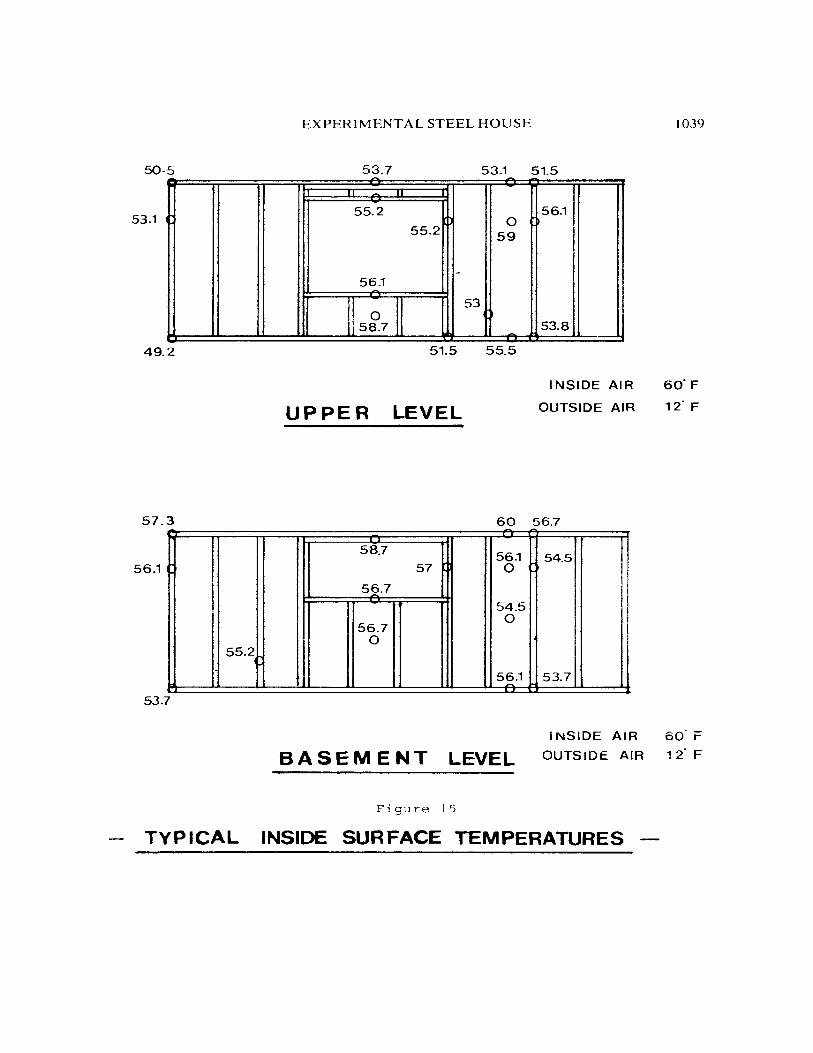
Figure 15 shows surface temperature readings for typical
walls on the main floor and basement levels.
It is interesting to note that although the inside air
temperature in both the basement and main floor levels
was the same, the framing temperatures in the basement
walls were generally a few degrees higher than those
in the main floor walls. Thus, the temperature gradients
and dust marking potentials are less. The stabilizing
and insulating effect of the soil outside the foundation
wall has resulted in a more even wall temperature
distribution.
(b) Thermocouple Measurements
Readings from Copper/Constantan thermocouples located
throughout the structure have been used to calculate
heat loss and condensation potentials. Figures 16 and
17 show typical interface temperatures for both wood

EXPERIMENTAL STEEL HOUSE 1019
and steel studs included in the same wall of the house.
The temperature drop across the steel stud is 9°F
(5°C) less than that across the wood stud, and because
of the higher thermal conductivity of steel, its
average temperature is also higher. At inside conditions
of 60°F (15.5°C) and 40% relative humidity, condensation
will occur at a surface temperature which is 35°F (l.7°C)
or lower. Consequently, condensation should occur in
the wood frame construction at the inside surface of
the sheathing, before it occurs in steel frame
construction (Figure 17).
According to our temperature measurements so far, the
two rows of thermal slots have resulted in a maximum
temperature drop of ll°F to l5°F (6.1°C to 8.3°C)
across the stud.
(c) Air Leakage
It has been estimated that infiltration of cold air
can account for up to 40% of the total heat loss from
a house (Appendix 1, Reference 3). If this infiltration
can be limited to provide the exact amount of fresh
air needed to maintain a comfortable environment
inside the house, a considerable saving of heating
energy could be realized.

1020 FOURTH SPECIALTY CONFERENCE
The major contributor to infiltration is the existence
of cracks and gaps in the structure caused by
dimensional inexactness of the materials, methods of
joining, changes in moisture content, etc. The
precision and exactness with which steel framing
components can be manufactured and erected, and its
ability to be "engineered", makes steel framing an
ideal candidate for a low air leakage "energy saving"
house.
A simple method for determining a leakage area,
equivalent to that of cracks and openings in the
outer shell of a house, has been developed by Ontario
Hydro (Appendix 1, Reference 8). It consists of
mounting an axial flow fan through a flexible plastic
film placed over a window. The sheet is taped to the
window frame forming an air tight seal. A rubber hose,
installed through the plastic film, is used to provide
an inclined manometer with a pressure tap to outside.
After all exterior doors and windows have been closed,
the exhaust fan is switched on and the static pressure
drop in the house noted. This pressure reading is
then converted to an equivalent leakage area (ELA)
by using a calibration chart.

EXPERIMENTAL STEEL HOUSE 1021
While the fan is operating, an observer searches for
openings in the structure that allow entry of cold air
from outside. During cold weather, outside air being
driven into the house can be detected by feel,
revealing sources of air leakage that would othe~1ise
not be observed.
To determine a figure of merit of leakage independent
of house size (leakage coefficient, LC), the leakage
area is divided by the house volume.
The typical range of equivalent leakage area (ELA) in
single family houses is between 0.7 and 3.0 square
feet (650 and 2,790 square em). The ELA measured
at the Experimental Steel House was 1.9 square feet
(1,765 square em). This value is quite acceptable,
particularly in view of the fact that the furnace
chimney and fireplace combustion intake were undampered,
and had a combined leakage area of 0.5 square feet
(465 square em).
The areas around electrical service, plumbing entrances
into the house, fireplace and exhaust fan dampers
are common entries for infiltrating air. In the

1022 FOURTH SPECIALTY CONFERENCE
Experimental House, these areas were evaluated as good
to above average. However, the front door and attic
access cover were observed to have a poor fit and the
side door into the garage had no weather stripping.
These are sources of high infiltration, which can
easily be eliminated before the next heating season.
Typical values for leakage coefficient (LC) range
between 0.6 and 1.5. Houses having coefficients
greater than 1.10 are not very tightly constructed
and probably have cold areas and high heating energy
consumption. Houses having leakage coefficients less
than 0.85 indicate tight construction and probably
suffer from associated problems of high indoor humidity,
wall staining and lingering household odours. The
leakage coefficient for the Experimental Steel House
was 0.96, exactly mid point in the range of coefficients
for "problem free" houses (i.e. between 0.85 and 1.1).
In comparison with information available f r om Ontario
Hydro, the Experimental Steel House appears to be
slightly better built (tighter) than frame houses of
traditional materials and construct ion (i.e. LC = 0.96
compared to LC = 0.99).

EXPERIMENTAL STEEL HOUSE 1023
CONCLUSIONS
(1} A house which extensively utilizes steel components can
be as attractive as any conventionally built house.
(2} The dimensional exactness of steel makes it ideally
suited for preengineered and simplified construction.
Even a relatively complex house design can be erected
quickly and easily.
(3) The weight of light gauge steel structural components is
generally considerably lower than that of equivalent
traditional components.
(4} Light gauge steel foundation wall panels can be designed
to withstand relatively high soil pressures. Deflections
and stresses can be kept within acceptable limits.
(5} The thermal performance of properly designed steel components
can be made equal to, or often better than, that of
conventional construction materials.
(6) Steel structural members can be designed to avoid excessive
condensation. The point of condensation in the steel stud
wall was closer to the exterior skin of the house, and
therefore, better than the wood stud wall.

1024 FOURTH SPECIALTY CONFERENCE
(7) Under these test conditions, the static and dynamic
characteristics of light gauge steel residential floor
joists are every bit as good as wood joists.
(8) When using steel components, a "tight" house can be built,
which is very desirable from an energy conservation point
of view.

EXPERIMENTAL STEEL HOUSE 1025
APPENDIX 1 - REFERENCES
(1) "ASHRAE Handbook of Fundamentals", American Society of
Heating, Refrigeration and Air Conditioning Engineers,
New York, New York, 1972.
(2) "Design Criteria for Basement Foundation Systems in
Canadian Housing", The Technical Research Committee,
Housing and Urban Development Association of Canada,
Toronto, Canada, 1975.
(3) "Energy Saving Homes - The Arkansa Story", Report No. 1,
OWens Corning Fiberglas, Toledo, Ohio, June 1976.
(4) "Exterior Wall Steel Stud Systems", Acceptance Bulletin,
Central Mortgage and Housing Corporation, Ottawa, Canada.
(5) "Field Performance of Gravel Pad Drainage Installations
Under Basements", The Technical Research Committee,
Housing and Urban Development Association of Canada,
Toronto, Canada.
(6) Latta J. K., "Walls, Windows and Roofs for the Canadian
Climate", Special Technical Publication No. 1, Division
of Building Research, National Research Council of Canada,
Ottawa, Canada, 1973.

1026 FOURTH SPECIALTY CONFERENCE
(7) Lenzen K. H., "Vibration of Steel Joist Concrete Floor
Slabs", AISC Engineering Journal, July 1966.
(8) "Research Quarterly", Ontario Hydro, Volume 26 Number 4,
Fourth Quarter, 1974.
(9) "Residential Standard 1975", Associate Committee on the
National Building Code, National Research Council of
Canada, Ottawa, Canada.
(10) Taos. s. and Hamilton J. J., "Performance of the Mark
IX Steel Basement to 31 January 1975", Division of
Building Research, National Research Council of Canada,
Ottawa, Canada, Technical Note No. 595, November 1975.
(11) Wiss John F. and Parmelee R. A., "Human Perception of
Transient Vibrations", Journal of the Structural Division,
ASCE, Volume 100 Number ST4, April 1974.

EXPERIMENTAL STEEL HOUSE 1027
TABLE 1 - PROPERTIES OF TEST JOISTS
"I II SHAP.E STEEL "C II SHAPE STEEL \·loon
OvERALL DIMENSION IN, 1.7 X 7,375 1.525 X 7.25 1-1/2 X 9-1/4 (eM) (4,32 X 18.73) (3 , 87 X 18 , 4) (3,8 X 23,5)
MATERIAL THICKNESS IN, CHORD ,03~ ( .99) .Ot\1 1-1/2 (MM) HEB .025 (.64) <1.55) (38)
WEIGHT PER FooT LB./FT. 1.803 2.337 3.18 (KG/M) (2.68) (3.49) (4,73)
MOMENT OF INERTIA IN4q 4.453 4.619 98.932 <eM > <185.3) <192.3) (4117.9)
STIFFNESS Elx LB.IN~2 X 1g~ 133.59 138.57 118.72 (KG M X 10 ) (3.909) (4.055) (3.474)
CROSS SECTIONAL '\ REA I N~2 .500 .660 13.875 (eM > (3.23) (4.26) (89.52)
TABLE 2 - lATERAL i:.ARni PP.~~sURE MEASUr.c:ME~JTS <P~II (KG/CM.r..)
CELL OcT. Dec, '\PRIL MAY JUNE AuG. fcT. tlo, 26/76 9/7t\ 12177 26/77 28177 15/77 f/77
837 .47 .54 .95 .85 .5 .3 .~4 <.033) (. 038) < .OE7> < .OfO> ( .035) ( .021> ( .045)
G3& 1.3G 1.5 l.C7 1.77 1.75 !.67 1.75 <.09f) ( .1('!5) ( .117> (.1,4) <.1?.3) (.117> (.1?.::J)
839 .79 .52 1.48 1.4 1.75 l.SLi 1.~9 ( .056) ( .037> ( .10/.f) (.098) ( .123) (.108) ( .098)
840 11.18 1.62 1.14 2.34 2.22 1.97 2.17 (,083) ( .115) (,150) (.164) (,156) ( .138) <.152)

1028 FOURTH SPECIALTY CONFERENCE
lABLE 3 - VIBRATION TEST DATA
%CRITICAL DAMPING fiLTERED
JOIST lYPE TF.ST COtiDITimS ± 10% BAND WIDTH
00FASCO SOLID WEB BARE fLOOR <B. F.> 5.1 No loAD <NIL>
BARE FLOOR <B.F. > 24' (7,32 M) CONTINUOUS 10 PSF loA'- (l) 5.36
(48,8 KG/M ·)
12' (3,66 M) SPAN CARPTED (C)
~.77 No loAD 01/D
DoFAsco SoLID WEB B.F. 4.51 Nil
12' (3,66 M) SIMPLY SUPPORTED B. F. 4.92 l
12' (3,66 M) SPAN c
4.41 N/l
't" SHAPE B. F.
4.1 N/l
24' (7 ,32 M) CONTINUOUS B.F.
1.!.~7 L ,.
12' (3,66 M) SPAN '- 4.37 N/l
't" SHAPE B.F.
4.08 Nil
12' (3,66 M) SIMPLY SUPPORTED B.F.
4.6~ l
12' (3 ,66 td SPAN c
4.77 till WooD 2" x 10" B.F.
4.3 (5,1 CH X 25,L! CM) N/l
12' (3,66 M) SIMPLY SUPPORTED B.F.
4.92 L
12' (3.66 M) SPAN c
4.47 N/l
NATURAL FREQUENCY
C .P.M. <Hz>
1.,200 (20)
825 (13.75)
1.,250 (20.8)
1.,200 (20)
810 (13.5)
1.,200 (20)
1.,275 (21.25)
825 <13.75)
1.,250 (20.83)
1.,225 (20.42)
825 (13.75)
1.,350 (22.5)
1.,475 <24. 50>
825 <13.75)
1.,500 (25)

F.i.gure 1 FLAT-ROLLED STEEL IN THE DOFASCO EXPERIMENTAL STEEL HOUSE
COMPONENTS TOTAL WT. 1n LIS. COMPONENTS
A. HOUSE FRAMING COMPONENT§ B. QIIIIB IIUii.RIIIBI 1· STUDS 540·1 1· ROOFING 2· CORNER STUDS 30.0 2· SOFFIT end FASCIA 3· TOP l BOTTOM CHANNELS 247-2 3· STEEL SIDING 4· JOISTS 1138-4 4· EXTERIOR STEEL DOOR 5 · JOIST HANGERS 11·8 5· GARAGE DOOR 8 · SILLS··LINTELS·· INFILL 130·5 7· LINTEL BEAM 321-5 SUB-TOTAL
8· TRUSS BRACKET to-o C. SEPTIC TANK SUB-TOTAL
BA!i!iM!iNT WALL ~OMPQNEHT!i D. QTHER COMPQNENTS t · WALL PANELS
I)· HOUII .. 8 · 8:hlgh •· 3215-3 1 · RAINWARE
b) · Gtrtgt·12 ·10hlgh ·- 2187·t 2· DUCT WORK
10· PANEL STIFFENERS 3· FURNACE ENCLOSURE
1)- House -- ·· ········ ·· ----· 173·2 4· FIREPLACE b)· Garage ............... .... 71·8 5· INTERIOR DOOR FRAMES
11 · CORNER STUDS 281.0 6· Bl- FOLD CLOSET DOORS
12· SILLS·· LINTELS ·· INFILL 148.0 7· CLOSET SHELVES 13· LINTEL BEAMS 286.0 8· KITCHEN VANITIES end CABINETS 14· JAMB REINFORCEMENTS 340.0 15· TOP CHANNEL SUB-TOTAL a)- House 248·8
b) -Gartge 113·3 18· FOOTING PLATE
e)- House 553·7 b)-Garage 254-4 TOTAL
MAIN FLOOR CENTER SUPPORT 17· CENTER BEAM 280.8
TOTAL 18 · JACK TELEPOST tO·O 19· INTERNAL PARTITION STUD 1183·5 20· INTERNAL PARTITIC~N CHANNELS 143·1
SUB-TOTAL 1.!!!!i.
THE QE.S.H.-•1 EXPERIMENTAL HOUSE IS A SPLIT LEVEL ENTRY HOUSE
24150 WITH A 1i 122 ATTACHED GARAGE
TOTAL WT. 1n LIS.
2118·8 278·4 718·5 300·0 110·0 ~
3883.5 m >< I 1000·0 "a m " ....
116·0 ~ 300-0 m 100-0
~ 200-0 216·0 >
80·0 r-37·0 til
~ 1152·0 m m 2201·0
r-
= 0 ~ til
LBS. 18,958·2 m
TONS. 9-48 -
-~~
'----------------------------------------------------------------------------'

1030 FOURT H SPECIALTY CONFERENCE
THERMAL STUD
THERMAL SLOTTING --'""""-~11-l
SUPPORT
FOOTING CHANNEL
Figure 2 - Stud and Footing Channel Details
EXPERIMENTAL STEEL HOUSE 1031
Figure 3 - Gravel Bed, Footing Channel and Basement Panels
Figure 4 - Lifting the Two Piece Center Beam into Position

1032 FOURTH SPECIALTY CONFERENCE
Figure 5 - Raising the Upper Wall into Position
Figure 6 - Installing the Light Gauge Steel Roof Tiles

EXPERIMENTAL STEEL HOUSE 1033
Figure 7 - The Finished House
Figure 8 - Instrumentation Cabinet

1034 FOURTH SPECIALTY CONFERENCE
Figure 9 - Joist Framing
Figure 10 - Concrete Blocks Used in Static Deflection Test

EXPERIMENTAL STEEL HOUSE 1035
Figure 11
DEFLECTION DATA FOR 12 Ft. FLOOR DECKS
-0 0 -....... tn '0 c:: ::1 0 Q.
0 < 0 -1
..... U)
0 ..,
20
10
j I'
"/ALLOWABLE DEFLECTION DESIGN LOAD (40 P.S.F.) V- DEFLECTION
~ SPAN 360 = 0 . . 40
-----e LIGHT GAUGE STEEL .. ! .. SHAPE
-----+WOOD
0 LIGHT GAUGE STEEL .. C .. SHAPE
0 ~----------------~----------------~--------------~ .1 .2 .3
MID -SPAN DEFLECTION (inches)

30
25
20t- -u, _. ~ ._.
~ z 151- w
~ w ~ _. Q. en
101-0
51-
I
" 0
Figure 12
LIGHT GAUGE STEEL ··t· SHAPED JOIST DECK
DISPLACEMENT vs. FREQUENCY
no load--
loaded ----- (10pst)
I " ' ' ' \ , ' r '
location : living room , , area : 12X 20 , span : 12 s.s.
' '
'/ I \
: \ f ,, I
I \
'r"" .. ~ 1000 2000 3000 4000
FREQUENCY (C. P.M.)
~
8 01
't1
g ~ = {I)
~ > ~ (") 0 z ~ ~ (") tr1

EXPERIMENTAL STEEL HOUSE 1037
Figu~e 13
SOIL PRESSURE DtAGRAM
X
w-LA-rE~ Son .. PRes~uR.e., EQ.U\'VAL.ENI F'L.U\0 !.0 PC.F
W•TOTAL- 1..~\E.RA.\... LOA.O - ~'2n'1
h • DEPT'-' OF e.AC.K.F ''-'-
)-I- I-4E.\G~I OF W A.L.\..
Rt•MA~\MUM 5'-'E.•R '= W-~
x = Poa~-r o~ MA.)(\MUM MOM~"-''T- hJ~hH M- MA~\MUM MOMENT-~ [ h,+ ~VfH ]

48 FEET
TEST SECTIONS . . . .
6 6 6 6 FOUNDATION WALLS
0 0 0
Figure 14 LATERAL DISPLACEMENT<mm.) • OCTOBER 1976
0 APFdL 1977
+ OCTOBER 1977
-8 oc
EXPERIMENTAL STEEL HOUSE 1039
50-5 53.7 53.1 51.5
li ~
53.1 55.2 56.1
55.2 0
59
-56.1
53 0
58.7 53.8
49.2 51.5 55.5
INSIDE AIR 60. F
UPPER LEVEL OUTSIDE AIR 12· F
57.3 60 56.7
58.7 56.1 54.5 56.1 57 0
56.7
54.5 0
56.7 0
55.2
5~.1 53.7
53.7
INSIDE AIR 60. r BASEMENT LEVEL OUTSIDE AIR 12"F
Figure 15
TYPICAL INSIDE SURFACE TEMPERATURES

1040 FOURTH SPECIALTY CONFERENCE
( OUTSIDE TEMP.= 23"F )
( INSIDE TEMP. = 60. F )
Figure 16
SIDING
PLWOOD
SHEATHING
R·12 INSULATION
INTERFACE TEMPERATURES -MAIN WALL FRAME

Figure 17
TEMPERATURE PROfiLE ACROSS EXTERiOR WALL TEMPERATURE PROfiLE ACROSS EXTERIOR WALL -- -··· ·-· ·· · . ... ...... . .. ... .. . - . . . . .. . . ·- ... .... ..... . ....,._.--.. ·----·. --.... - ........ -.. _. .. ····-·· ... . _ ........ ···-·. ·-- .. - ·- --
- " ZDNE I (Stud) ')t \C ZDN£ I (Stud)
(Stud Space) (Stud Space)
il lit I 2 ~~
1 a s .... 1 't 1 I I . I I I t
:~:Ill 14 I
, ! • I I I • % l l% :J: I I
1: ~l a: I I ,0:: « 0: i • "m ~ I l l
I I '1-.,.
I~ r....
I . o 1 I l I lo ui tolll L!'l
~ I N II I I~ ~'I I ~I I I I ,.,. I I I
: t ~ I l I ...,lfi •• ,,
I I o· I )IL. ,u. LU IL I ~ ~ ! 1 I I I !!i l !II I •0 IO &U) J- I
I lU) tel tul I I I I I a: :II w I I 0: o. I 1 ~ *Saturation f5 ~ J I I I~ t..J _,
I I c. U\ - Point a. . Ul -~ 111 5 I i I l&.n i5 11t 5 I I I I JUl z z 1- I tl i.l I
,_ ..... c I ( I I I
,_ f + (I I I · l t I I I I I
1 I l
~ -- .... .. _ .. -t-·-.. - ··~ - - - .. ·-·- ··•--+--·-· -f I-- t t - -- + ·-- ---+---i--·-+---t
I 2 3 q ~
CROSS-SECTION (INCHES> NCDD STUD (ACTUAL>
I I 2 3 q ~
CROSS-SECTION CINCHES> STEEL STUD CRCTURL)
I. STEEL SIDIN8 2. SHEATHIN& 5. STUD 4. THERMAL BREAK 5. VAPOR BARRIER 6. DRYWALL
m >< ~
" ... 3: m 2! ~ > t"" (II
~ r!1 r!1 t"" ::z:: 0 c:: (II
r!1
-~ -