the diffraction-limited storage ring frontier. borland, the diffraction-limited storage ring...
TRANSCRIPT

The diffraction-limited storage ring frontier
Michael Borland for the APS-U Beam Physics Team10 July 2015Accelerator Systems DivisionArgonne National Laboratory
The s ubmitted manuscri pt has been created by UChicago Argonne, LLC, Operator of Argonne National Laboratory (“Argonne”). Argonne, a U.S. Department of Energy Office of Science laboratory, is operated under Contract No. DE-AC02-06CH11357. The U.S. Government retains for itself, and others acting onits behalf, a pai d-up nonexclusive, irrevocable worl dwi de license in sai d article to reproduce, prepare derivative works, distri bute copies to the public, and perform publicly and dis play publicly, by or on behalf of the Government.
Work supported by the U.S. Department of Energy, Office of Science, under Contract No. DE-AC02-06CH11357.

M. Borland, The diffraction-limited storage ring frontier, July 2015, Varenna, Italy 2
Outline
X-ray brightness, beam emittance, and the diffraction limit Multi-bend achromat lattices Challenges and solutions
– Magnet strength– Vacuum systems– Tolerances and correction– Nonlinear dynamics– Injection– Intrabeam scattering– Beam lifetime
Advanced IDs and x-ray performance Summary

M. Borland, The diffraction-limited storage ring frontier, July 2015, Varenna, Italy 3
X-ray Brightness
Brightness can be expressed as
Approximate description of single-electron undulator radiation distribution (“intrinsic” or “diffraction” distribution)1
Electron beam provides “diffraction-limited” radiation when
In this case, the coherent fraction can be quite high
(simplification)
1P. Elleaume, in Wigglers, Undulators, and Their Applications, 2003.
M. Borland, The diffraction-limited storage ring frontier, July 2015, Varenna, Italy 4
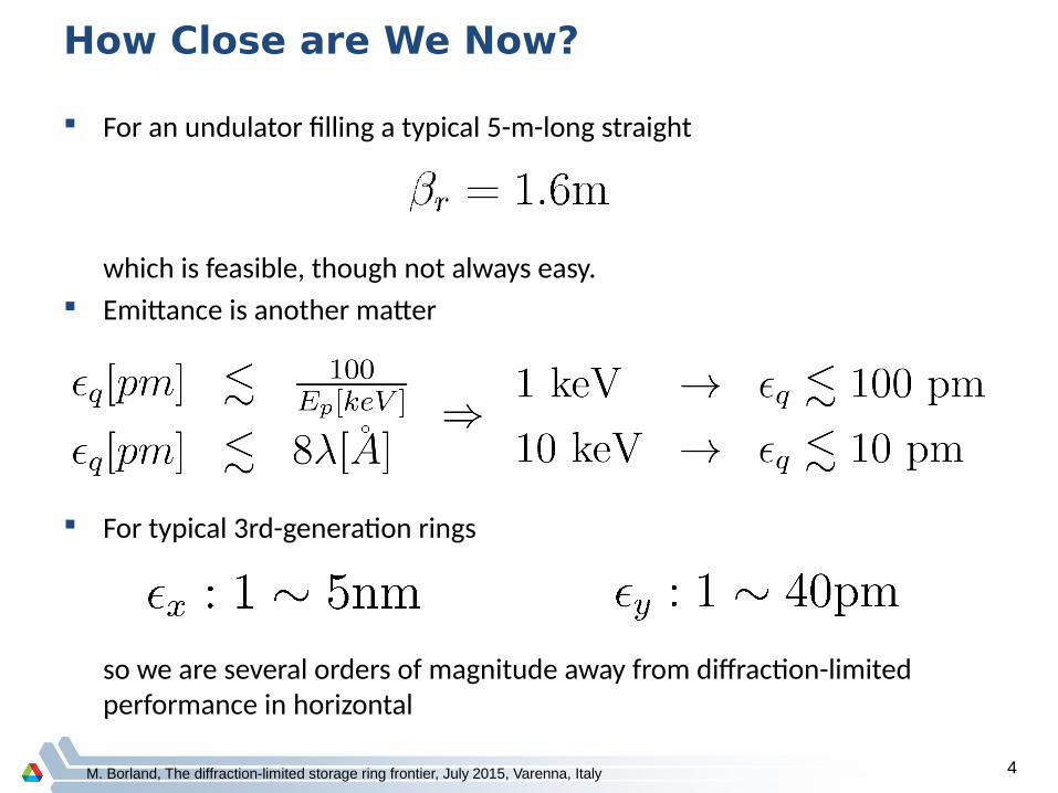
How Close are We Now?
For an undulator filling a typical 5-m-long straight
which is feasible, though not always easy. Emittance is another matter
For typical 3rd-generation rings
so we are several orders of magnitude away from diffraction-limited performance in horizontal

M. Borland, The diffraction-limited storage ring frontier, July 2015, Varenna, Italy 5
Emittance Scaling
Emittance is governed by1
Simple explanation– Emittance is driven by randomness of photon emission in presence of
dispersive (energy-dependent) orbits– Breaking up dipoles and putting focusing (quadrupoles) between the
parts allows tightly controlling the magnitude of dispersive orbits First explorations in mid 1990's2-5
Various advanced ring designs help illustrate potential and challenges– MAX-IV (Sweden)6
– ALS-U (US)7
– ESRF-II (France)8
– APS-U (US)9
Many projects omitted in the interest of time
1:J. Murphy, NSLS Light Source Data Booklet.2:Einfeld et al., NIM A 335, 19933:Joho et al., EPAC 94;4:Einfeld et al., PAC955:Kaltchev et al., PAC95.6:S. Leemann et al., PRSTAB 12, 120701 (2009).7:C. Steier, SRN 27, 19 (2014).8:L. Farvacque et al., IPAC13, 79 (2013).9:G. Decker, SRN 27, 13 (2014).
M. Borland, The diffraction-limited storage ring frontier, July 2015, Varenna, Italy 6
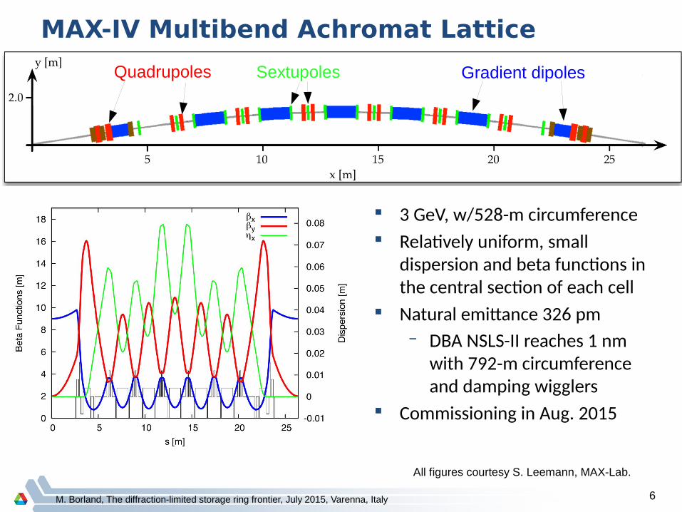
MAX-IV Multibend Achromat Lattice
3 GeV, w/528-m circumference Relatively uniform, small
dispersion and beta functions in the central section of each cell
Natural emittance 326 pm– DBA NSLS-II reaches 1 nm
with 792-m circumference and damping wigglers
Commissioning in Aug. 2015
All figures courtesy S. Leemann, MAX-Lab.
Gradient dipolesQuadrupoles Sextupoles
C. Steier, ALS SAC, ALS-U R+D, 2015-3-237
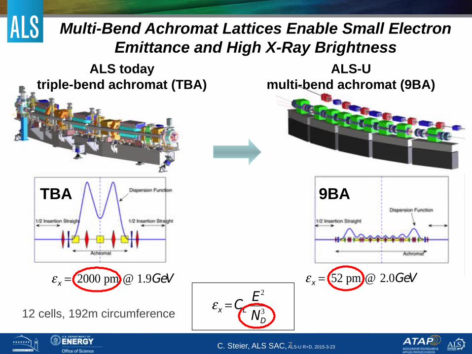
Multi-Bend Achromat Lattices Enable Small Electron Emittance and High X-Ray Brightness
ALS-Umulti-bend achromat (9BA)
ALS todaytriple-bend achromat (TBA)
TBA 9BA
7
x CL
E2
ND3
x 2000 pm @ 1.9GeV x 52 pm @ 2.0GeV
12 cells, 192m circumference

Blue: Dipoles Red: Quadrupoles Green: sextupoles
The ESRF 6 GeV low emittance lattice
Proposed Hybrid 7 Bend lattice Ex = 150 pm.rad
●7 bending magnets D1to D7● reduce the horizontal emittance● Diffraction-limited to 0.7 keV
●Space between D1-D2 and D6-D7● β-functions and dispersion allowed to
grow ● chromaticity correction with efficient
sextupoles
● Dipoles D1, D2, D6, D7 ● longitudinally varying field to further
reduce emittance
● Central part alternating ● combined dipole-quadrupoles D3-4-5● high-gradient focusing quadrupoles
D1 D2 D6 D7D3D4D5
Courtesy P. Raimondi, ESRF.
M. Borland, The diffraction-limited storage ring frontier, July 2015, Varenna, Italy 9
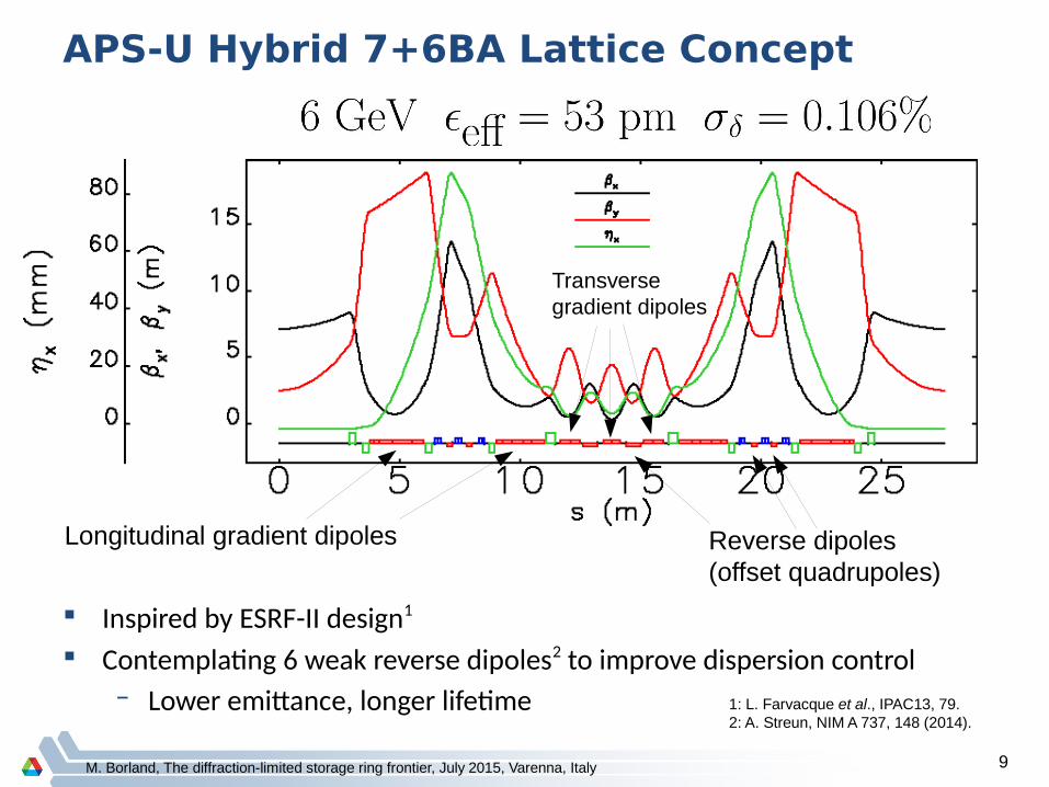
APS-U Hybrid 7+6BA Lattice Concept
Longitudinal gradient dipoles
Transversegradient dipoles
1: L. Farvacque et al., IPAC13, 79.2: A. Streun, NIM A 737, 148 (2014).
Inspired by ESRF-II design1
Contemplating 6 weak reverse dipoles2 to improve dispersion control– Lower emittance, longer lifetime
Reverse dipoles(offset quadrupoles)

M. Borland, The diffraction-limited storage ring frontier, July 2015, Varenna, Italy 10
Fundamental Challenges of Low Emittance
To reduce the dispersion function, must focus more frequently and more strongly
Many strong quadrupoles → larger natural chromaticity Chromaticity sextupoles are less effective because of small dispersion Very strong sextupoles introduce strong
higher-order aberrations– Increased difficulties with
injection, beam lifetime We used a model 4.5 GeV,
600-m ring to study scalingof ring parameters1
1: M. Borland, et al. J. Synch. Rad 21, 912-936 (2014).
1/Nd
2.9
Nd = N
sM

M. Borland, The diffraction-limited storage ring frontier, July 2015, Varenna, Italy 11
Scaling of Magnet Strengths
Emittance decrease is dramatic, but...– Gradients grow like N
d2
– Average dispersion drops like 1/Nd
2
– Sextupole strength grows like Nd
3
Need smaller magnet aperturesto produce these strengths
1/Nd
1.9 SD:Nd
2.9
SF:Nd
3.2
QF:Nd
1.8
Bend/QD:Nd
2.4
M. Borland, The diffraction-limited storage ring frontier, July 2015, Varenna, Italy 12
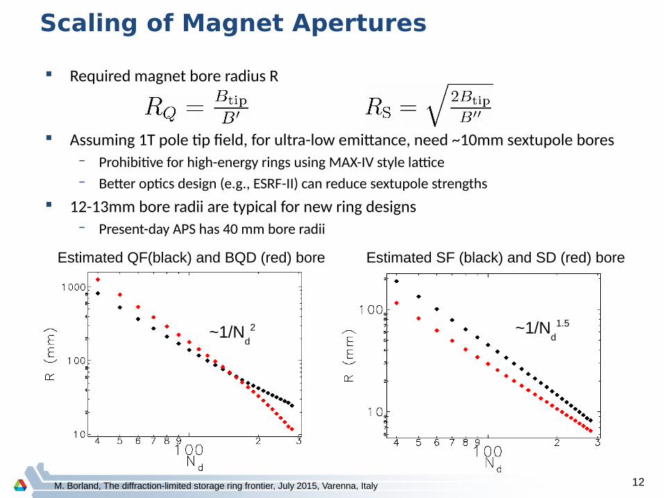
Scaling of Magnet Apertures
Required magnet bore radius R
Assuming 1T pole tip field, for ultra-low emittance, need ~10mm sextupole bores– Prohibitive for high-energy rings using MAX-IV style lattice– Better optics design (e.g., ESRF-II) can reduce sextupole strengths
12-13mm bore radii are typical for new ring designs– Present-day APS has 40 mm bore radii
Estimated QF(black) and BQD (red) bore Estimated SF (black) and SD (red) bore
~1/Nd
2 ~1/Nd
1.5
M. Borland, The diffraction-limited storage ring frontier, July 2015, Varenna, Italy 13
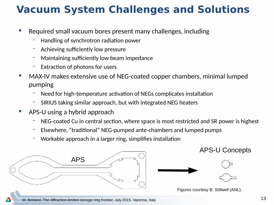
Vacuum System Challenges and Solutions
Required small vacuum bores present many challenges, including– Handling of synchrotron radiation power– Achieving sufficiently low pressure– Maintaining sufficiently low beam impedance– Extraction of photons for users
MAX-IV makes extensive use of NEG-coated copper chambers, minimal lumped pumping
– Need for high-temperature activation of NEGs complicates installation– SIRIUS taking similar approach, but with integrated NEG heaters
APS-U using a hybrid approach – NEG-coated Cu in central section, where space is most restricted and SR power is highest– Elsewhere, “traditional” NEG-pumped ante-chambers and lumped pumps– Workable approach in a larger ring, simplifies installation
APS
APS-U Concepts
Figures courtesy B. Stillwell (ANL).

M. Borland, The diffraction-limited storage ring frontier, July 2015, Varenna, Italy 14
Impedance and Single Bunch Current Limit1
APS-U targeting 4.2 mA/bunch for48-bunch, 200-mA timing mode
– Requires careful iteration ofvacuum system design
– Design of a lattice with sufficientpositive residual chromaticity
Prediction is that 4.2 mA is possiblewith chromaticity of +5
– With latest design, margin higherthan shown 1: R. Lindberg et al., IPAC15, TUPJE077, TUPJE078.

M. Borland, The diffraction-limited storage ring frontier, July 2015, Varenna, Italy 15
Longitudinal phase space impacted by impedance
200 mA in 48 bunches
200 mA in 324 bunches
Intense bunches are disrupted by microwave instability
– No beam loss, but energy spread is inflated
Threshold is at ~0.5 mA/bunch– In APS today, threshold is ~5
mA/bunch
M. Borland, The diffraction-limited storage ring frontier, July 2015, Varenna, Italy 16
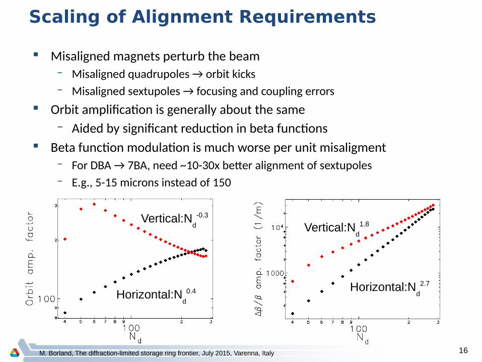
Scaling of Alignment Requirements
Misaligned magnets perturb the beam– Misaligned quadrupoles → orbit kicks– Misaligned sextupoles → focusing and coupling errors
Orbit amplification is generally about the same– Aided by significant reduction in beta functions
Beta function modulation is much worse per unit misaligment– For DBA → 7BA, need ~10-30x better alignment of sextupoles– E.g., 5-15 microns instead of 150
Horizontal:Nd
0.4
Vertical:Nd
-0.3
Vertical:Nd
1.8
Horizontal:Nd
2.7
M. Borland, The diffraction-limited storage ring frontier, July 2015, Varenna, Italy 17
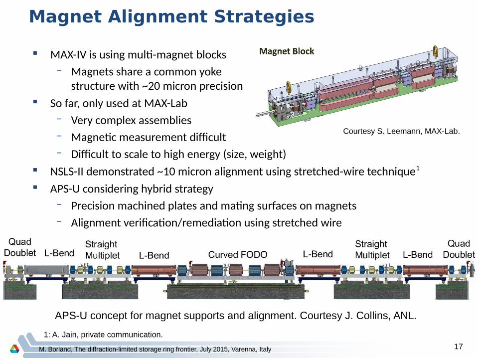
Magnet Alignment Strategies
MAX-IV is using multi-magnet blocks– Magnets share a common yoke
structure with ~20 micron precision So far, only used at MAX-Lab
– Very complex assemblies– Magnetic measurement difficult– Difficult to scale to high energy (size, weight)
NSLS-II demonstrated ~10 micron alignment using stretched-wire technique1
APS-U considering hybrid strategy– Precision machined plates and mating surfaces on magnets– Alignment verification/remediation using stretched wire
APS-U concept for magnet supports and alignment. Courtesy J. Collins, ANL.
Courtesy S. Leemann, MAX-Lab.
1: A. Jain, private communication.
M. Borland, The diffraction-limited storage ring frontier, July 2015, Varenna, Italy 18
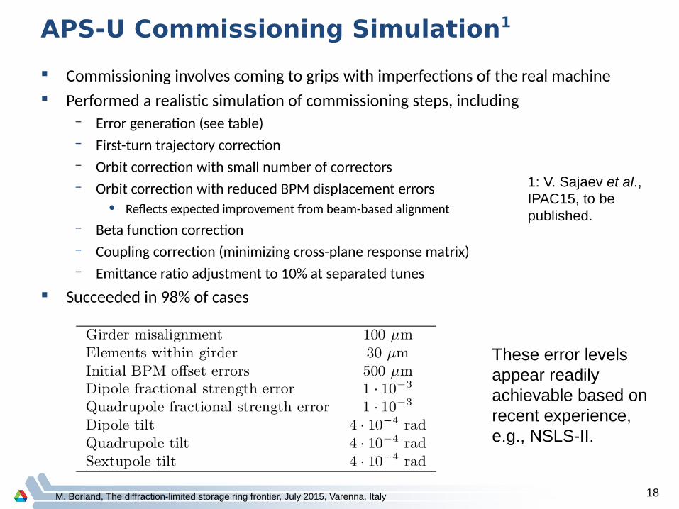
APS-U Commissioning Simulation1
Commissioning involves coming to grips with imperfections of the real machine Performed a realistic simulation of commissioning steps, including
– Error generation (see table)– First-turn trajectory correction– Orbit correction with small number of correctors– Orbit correction with reduced BPM displacement errors
• Reflects expected improvement from beam-based alignment– Beta function correction – Coupling correction (minimizing cross-plane response matrix)– Emittance ratio adjustment to 10% at separated tunes
Succeeded in 98% of cases
These error levelsappear readily achievable based onrecent experience,e.g., NSLS-II.
1: V. Sajaev et al.,IPAC15, to bepublished.

M. Borland, The diffraction-limited storage ring frontier, July 2015, Varenna, Italy 19
Tracking-based Optimization1,2
Tracking-based optimization allows directly optimizing lattice and sextupoles for– Large dynamic acceptance– Large Touschek lifetime (via local momentum acceptance)
Unlike theoretical approaches, can include– Effects of likely errors– Effects of radiation damping and synchrotron motion– Vacuum chamber dimensions
Tracking-based optimizationmakes significant improvementsstarting from ESRF-II scheme, even with initial tunes chosen for fourth-order achromatic condition.
Starting point
1: See citations in M. Borland, IPAC12, 1035.2: M. Borland, et al. J. Synch. Rad 21, 912-936 (2014).

M. Borland, The diffraction-limited storage ring frontier, July 2015, Varenna, Italy 20
APS-U 10th-Percentile DA w/ID Chambers
Compared to a typical wide ID chamber, round or narrow chambers have little impact
Option for vertically-deflecting devices, round-bore helical devices– Such devices not readily compatible with accumulation-based operation
M. Borland, The diffraction-limited storage ring frontier, July 2015, Varenna, Italy 21
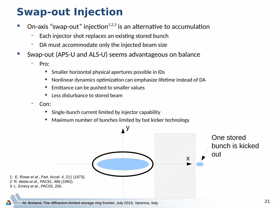
Swap-out Injection On-axis “swap-out” injection1,2,3 is an alternative to accumulation
– Each injector shot replaces an existing stored bunch– DA must accommodate only the injected beam size
Swap-out (APS-U and ALS-U) seems advantageous on balance– Pro:
• Smaller horizontal physical apertures possible in IDs• Nonlinear dynamics optimization can emphasize lifetime instead of DA• Emittance can be pushed to smaller values• Less disturbance to stored beam
– Con:• Single-bunch current limited by injector capability• Maximum number of bunches limited by fast kicker technology
x
y
One storedbunch is kickedout
1: E. Rowe et al., Part. Accel. 4, 211 (1973).2: R. Abela et al., PAC91, 486 (1992).3: L. Emery et al., PAC03, 256.

22
Fast kicker magnets
storage ring bunches transferred to accumulatoraccumulator bunches transferred to storage ring
New accumulator ring
New ALS storage ring
Swap-out injection [with an accumulator] was first proposed by M. Borland for possible APS upgrades
Swapping Accumulator and Storage Ring Beams
22Courtesy C. Steier, ALS.
M. Borland, The diffraction-limited storage ring frontier, July 2015, Varenna, Italy 23
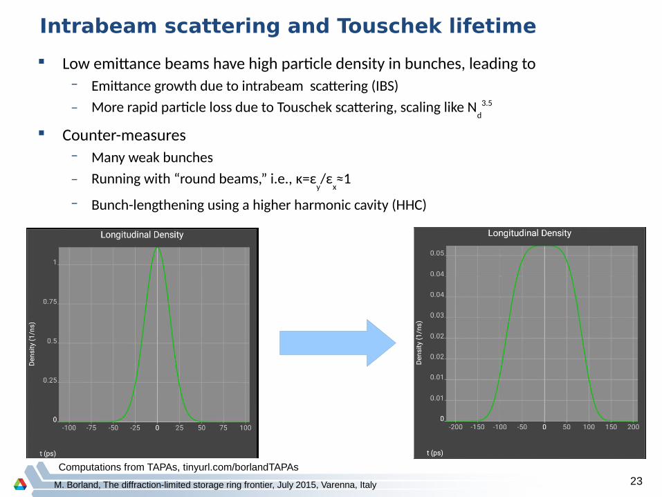
Intrabeam scattering and Touschek lifetime
Computations from TAPAs, tinyurl.com/borlandTAPAs
Low emittance beams have high particle density in bunches, leading to– Emittance growth due to intrabeam scattering (IBS)– More rapid particle loss due to Touschek scattering, scaling like N
d3.5
Counter-measures– Many weak bunches– Running with “round beams,” i.e., κ=ε
y/ε
x≈1
– Bunch-lengthening using a higher harmonic cavity (HHC)

M. Borland, The diffraction-limited storage ring frontier, July 2015, Varenna, Italy 24
Suppression of Intrabeam Scattering (IBS)
Multiple scattering within a bunch leads to emittance and energy spread growth IBS effects not negligible even for 324 bunch flat beams HHC provides ~4-fold reduction in emittance increase from IBS “Round beams” also effective
– Most readily compatible with on-axis injection
Flat beams (κ=0.1) Round beams (κ≈1)
324 bunches 48 bunches 324 bunches 48 bunches

M. Borland, The diffraction-limited storage ring frontier, July 2015, Varenna, Italy 25
Effect of HHC (Passive, Optimal Detuning)
Rms bunch duration exceeds 75ps– 12.5 ps at zero current
Microwave instability is considerably quieter
324 bunch case has a somewhat split bunch
200 mA in 48 bunches
200 mA in 324 bunches
For 48 bunches, Touschek lifetime improves ~2-fold
– Less than nominal 4-fold because MWI already lengthened the bunch
For 324 bunches, Touschek lifetime improves ~4-fold
M. Borland, The diffraction-limited storage ring frontier, July 2015, Varenna, Italy 26
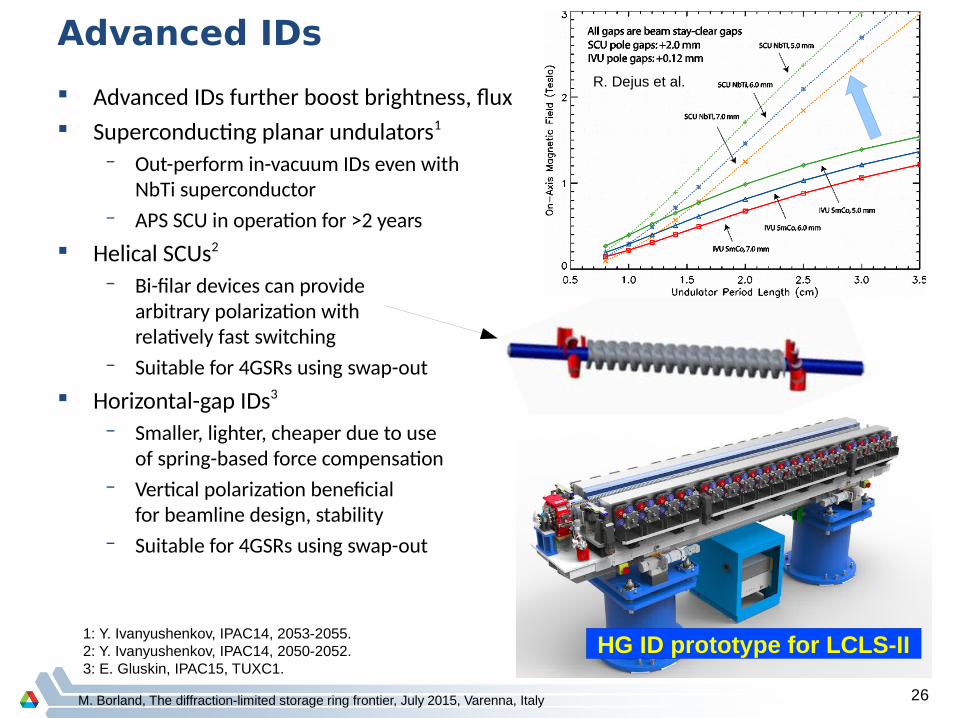
Advanced IDs
Advanced IDs further boost brightness, flux Superconducting planar undulators1
– Out-perform in-vacuum IDs even with NbTi superconductor
– APS SCU in operation for >2 years Helical SCUs2
– Bi-filar devices can providearbitrary polarization withrelatively fast switching
– Suitable for 4GSRs using swap-out Horizontal-gap IDs3
– Smaller, lighter, cheaper due to useof spring-based force compensation
– Vertical polarization beneficialfor beamline design, stability
– Suitable for 4GSRs using swap-out
R. Dejus et al.
1: Y. Ivanyushenkov, IPAC14, 2053-2055.2: Y. Ivanyushenkov, IPAC14, 2050-2052.3: E. Gluskin, IPAC15, TUXC1.
HG ID prototype for LCLS-II
M. Borland, The diffraction-limited storage ring frontier, July 2015, Varenna, Italy 27
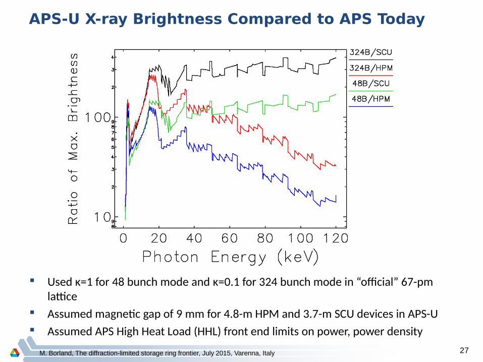
APS-U X-ray Brightness Compared to APS Today
Used κ=1 for 48 bunch mode and κ=0.1 for 324 bunch mode in “official” 67-pm lattice
Assumed magnetic gap of 9 mm for 4.8-m HPM and 3.7-m SCU devices in APS-U Assumed APS High Heat Load (HHL) front end limits on power, power density
M. Borland, Ultimate Storage Rings, GRC 8/13 28
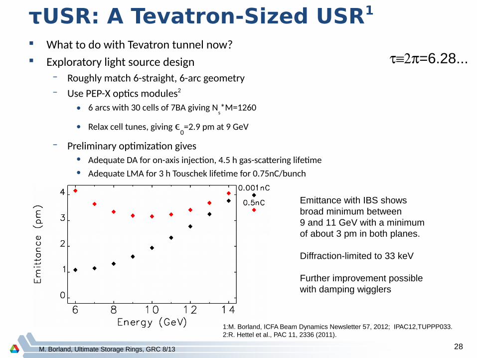
What to do with Tevatron tunnel now? Exploratory light source design
– Roughly match 6-straight, 6-arc geometry– Use PEP-X optics modules2
• 6 arcs with 30 cells of 7BA giving Ns*M=1260
• Relax cell tunes, giving 0=2.9 pm at 9 GeV
– Preliminary optimization gives • Adequate DA for on-axis injection, 4.5 h gas-scattering lifetime• Adequate LMA for 3 h Touschek lifetime for 0.75nC/bunch
τUSR: A Tevatron-Sized USR1
1:M. Borland, ICFA Beam Dynamics Newsletter 57, 2012; IPAC12,TUPPP033.2:R. Hettel et al., PAC 11, 2336 (2011).
=6.28...
Emittance with IBS showsbroad minimum between9 and 11 GeV with a minimumof about 3 pm in both planes.
Diffraction-limited to 33 keV
Further improvement possiblewith damping wigglers

M. Borland, Ultimate Storage Rings, GRC 8/13 29
Explore light source physics
A free Android app is available that lets you explore storage ring scaling Also has synchrotron radiation calculations, FELs, top-up/swap-out, etc. Search for “TAPAs Accelerator Physics” on the Google store
Ring scaling Undulator radiation FEL estimation

M. Borland, The diffraction-limited storage ring frontier, July 2015, Varenna, Italy 30
Conclusions
3rd generation storage ring light sources are among the most successful scientific tools ever built
We’ve learned a great deal since the first of these sources began operating ~20 years ago
There is world-wide activity to design and build 4th generation storage ring light sources
100x increases in brightness and 10x increases in flux are within reach
Challenges are many, but all appear manageable Another order of magnitude appears feasible with much larger rings

M. Borland, The diffraction-limited storage ring frontier, July 2015, Varenna, Italy 31
Acknowledgments
APS Upgrade Beam Physics team:
A. Blednykh (BNL), T. Berenc, M. Borland, J. Calvey, J. Dooling, L. Emery, K. Harkay, R. Lindberg, V. Sajaev, Y. Sun, A. Xiao
Also contributing:
H. Cease, J. Carter, J. Carwardine, G. Decker, S. Henderson, A. Jain, M. Jaski, J. Kerby, R. Soliday, B. Stillwell, A. Zholents, ...
Early version of H7BA lattice used file provided by ESRF
Computing: – Argonne Laboratory Computing Resources Center (LCRC), Blues cluster– Accelerator Systems Division, Weed cluster