the development of an object-oriented software development
TRANSCRIPT
Department of Computer Engineering1
Sharif University of Technology
Object-Oriented Design
Lecturer: Raman Ramsin
Lecture 4: Use Case Modeling
Part 1
Object-Oriented Design – Lecture 4
Department of Computer Engineering2
Sharif University of Technology
Four Steps of requirements capture
1. List candidate requirements
2. Understand system context
3. Capture functional requirements
4. Capture nonfunctional requirements

Object-Oriented Design – Lecture 4
Department of Computer Engineering3
Sharif University of Technology
Activities of requirements workflow
Capture Functional Requirements
1. Find actors and use cases
2. Prioritize use cases
3. Detail use cases
4. Prototype user interface
5. Structure the use-case model

Object-Oriented Design – Lecture 4
Department of Computer Engineering4
Sharif University of Technology
Use case modeling
Use case modeling typically proceeds as follows:
Find a candidate system boundary; You generally begin with some initial estimate of where the system boundary lies, to help you scope the modeling activity.
Find the actors.
Find the use cases:
specify the use case;
identify key alternative flows.
Iterate until use cases, actors, and system boundary are stable.
Object-Oriented Design – Lecture 4
Department of Computer Engineering5
Sharif University of Technology
Use Case Model
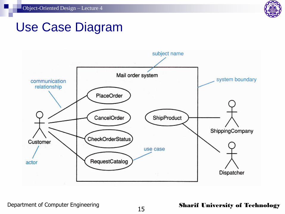
Four components: System boundary - a box drawn around the use
cases to denote the edge or boundary of the system being modeled. This is known as the subject in UML2.
Actors - roles played by people or things that use the system.
Use cases - things that the actors can do with the system.
Relationships - meaningful relationships between actors and use cases.
Object-Oriented Design – Lecture 4
Department of Computer Engineering6
Sharif University of Technology
The subject (system boundary)
The subject is defined by who or what uses the system (i.e., the actors) and what specific benefits the system offers to those actors (i.e., the use cases).
The subject is drawn as a box, labeled with the name of the system
The actors are drawn outside the boundary and the use cases inside.
Use case modeling starts with only a tentative idea of where the subject actually lies.
As actors and use cases are found, the subject becomes more and more sharply defined.
Object-Oriented Design – Lecture 4
Department of Computer Engineering7
Sharif University of Technology
Actors
An actor specifies a role that some external entity adopts when interacting with the system directly.
It may represent a role played by:
a user
another system
a piece of hardware
In UML 2, actors may also represent other subjects, giving a way to link different use case models.

Object-Oriented Design – Lecture 4
Department of Computer Engineering8
Sharif University of Technology
Actors: Notation
Can be shown as a class icon stereotyped «actor» or as the "stick man" actor icon.
“Stick-man" form usually used to represent roles that are likely to be played by people, and the class icon form to represent roles likely to be played by other systems.
Accounting

Object-Oriented Design – Lecture 4
Department of Computer Engineering9
Sharif University of Technology
Actors: Important Notes
Although actors themselves are always external to the system, systems often maintain some internal representation of one or more actors.
Time as an actor: When you need to model things that happen to your system at
a specific point in time but which don't seem to be triggered by any actor; e.g. an automatic system backup that runs every evening.
Object-Oriented Design – Lecture 4
Department of Computer Engineering10
Sharif University of Technology
Identifying Actors
Need to consider who or what uses the system, and what roles they play in their interactions with the system.
Asking the following questions helps identify actors:
Who or what uses the system?
What roles do they play in the interaction?
Who installs the system?
Who or what starts and shuts down the system?
Who maintains the system?
What other systems interact with this system?
Who or what gets and provides information to the system?
Does anything happen at a fixed time?
Object-Oriented Design – Lecture 4
Department of Computer Engineering11
Sharif University of Technology
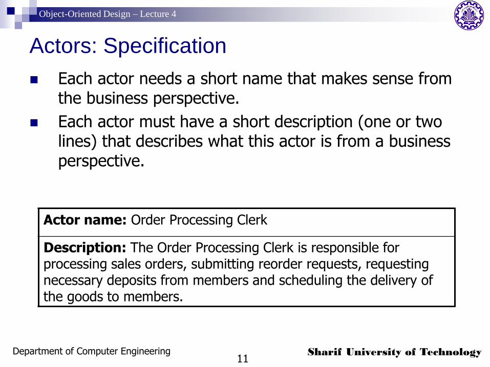
Actors: Specification
Each actor needs a short name that makes sense from the business perspective.
Each actor must have a short description (one or two lines) that describes what this actor is from a business perspective.
Actor name: Order Processing Clerk
Description: The Order Processing Clerk is responsible for processing sales orders, submitting reorder requests, requesting necessary deposits from members and scheduling the delivery of the goods to members.
Object-Oriented Design – Lecture 4
Department of Computer Engineering12
Sharif University of Technology
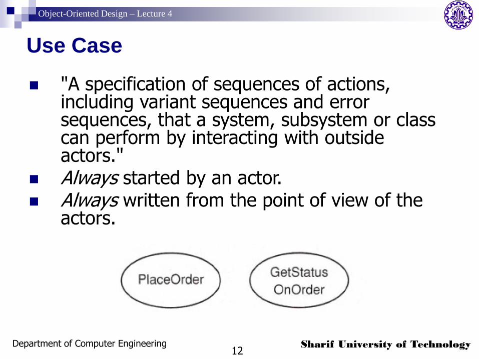
Use Case
"A specification of sequences of actions, including variant sequences and error sequences, that a system, subsystem or class can perform by interacting with outside actors."
Always started by an actor. Always written from the point of view of the
actors.
Object-Oriented Design – Lecture 4
Department of Computer Engineering13
Sharif University of Technology
Identifying Use Cases
The best way of identifying use cases is to start with the list of actors, and then consider how each actor is going to use the system.
Each use case must be given a short, descriptive name that is a verb phrase.
Identifying use cases may also result in finding new actors.
Object-Oriented Design – Lecture 4
Department of Computer Engineering14
Sharif University of Technology
Identifying Use Cases: Helpful Questions
The following list of questions helps identify the use cases:
What functions will a specific actor want from the system?
Does the system store and retrieve information? If so, which actors trigger this behavior?
What happens when the system changes state (e.g., system start and stop)? Are any actors notified?
Do any external events affect the system? What notifies the system about those events?
Does the system interact with any external system?
Does the system generate any reports?
Object-Oriented Design – Lecture 4
Department of Computer Engineering15
Sharif University of Technology
Use Case Diagram

Object-Oriented Design – Lecture 4
Department of Computer Engineering16
Sharif University of Technology
Project Glossary
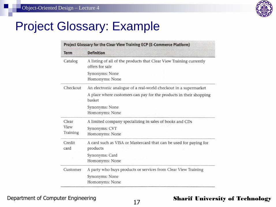
The glossary provides a dictionary of key business terms and definitions.
It should be understandable by everyone in the project, including all the stakeholders.
As well as defining key terms, the project glossary must resolve synonyms and homonyms.
Object-Oriented Design – Lecture 4
Department of Computer Engineering17
Sharif University of Technology
Project Glossary: Example

Object-Oriented Design – Lecture 4
Department of Computer Engineering18
Sharif University of Technology
Activities of requirements workflow
Capture Functional Requirements
1. Find actors and use cases
2. Prioritize use cases
3. Detail use cases
4. Prototype user interface
5. Structure the use-case model
Object-Oriented Design – Lecture 4
Department of Computer Engineering19
Sharif University of Technology
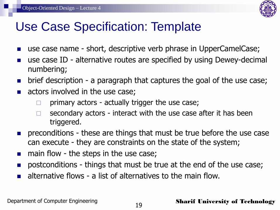
Use Case Specification: Template
use case name - short, descriptive verb phrase in UpperCamelCase;
use case ID - alternative routes are specified by using Dewey-decimal numbering;
brief description - a paragraph that captures the goal of the use case;
actors involved in the use case;
primary actors - actually trigger the use case;
secondary actors - interact with the use case after it has been triggered.
preconditions - these are things that must be true before the use case can execute - they are constraints on the state of the system;
main flow - the steps in the use case;
postconditions - things that must be true at the end of the use case;
alternative flows - a list of alternatives to the main flow.
Object-Oriented Design – Lecture 4
Department of Computer Engineering20
Sharif University of Technology
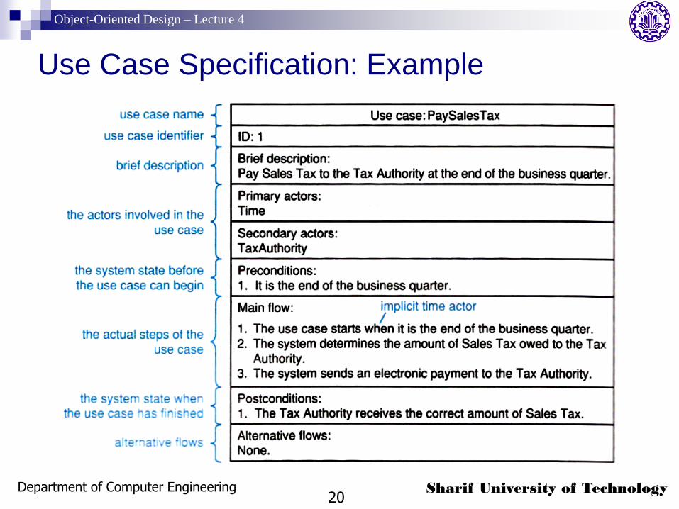
Use Case Specification: Example

Object-Oriented Design – Lecture 4
Department of Computer Engineering21
Sharif University of Technology
Use Case: Flows
The steps in a use case are listed in flows of events, described in structured language.
Every use case has one main flow (Primary Scenario), which lists the steps in a use case that capture the situation where everything goes as expected and desired.
Alternative flows (Secondary Scenarios) are deviations from the main flow, and can capture errors, branches, and interrupts to the main flow.
The main flow always begins by the primary actor doing something to trigger the use case. Time can be an actor, so the use case may also start with a time expression in place of the actor.
Object-Oriented Design – Lecture 4
Department of Computer Engineering22
Sharif University of Technology
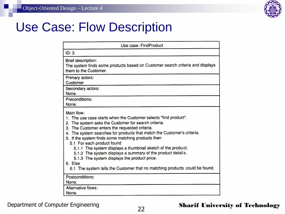
Use Case: Flow Description

Object-Oriented Design – Lecture 4
Department of Computer Engineering23
Sharif University of Technology
Use Case: Alternative Flows
Do not return to the main flow; because they often deal with errors and exceptions to the main flow and tend to have different postconditions.
Should preferably be documented separately.
May be triggered in three different ways, which should be stated in their flow descriptions: instead of the main flow: triggered by the primary actor, it
effectively replaces the use case entirely.
after a particular step in the main flow
at any time during the main flow

Object-Oriented Design – Lecture 4
Department of Computer Engineering24
Sharif University of Technology
Use Case: Alternative Flow Example
Object-Oriented Design – Lecture 4
Department of Computer Engineering25
Sharif University of Technology
Use Case: Finding Alternative Flows
Identify alternative flows by inspecting the main flow. At each step in the main flow, look for:
possible alternatives to the main flow;
errors that might be raised in the main flow;
interrupts that might occur at a particular point in the main flow;
interrupts that might occur at any point in the main flow.
Object-Oriented Design – Lecture 4
Department of Computer Engineering26
Sharif University of Technology
Reference
Arlow, J., Neustadt, I., UML 2 and the Unified Process: Practical Object-Oriented Analysis and Design, 2nd Ed. Addison-Wesley, 2005.