the design of reinforced masonry and precast concrete lintels
TRANSCRIPT
PDHonline Course S126 (1 PDH)
The Design of Reinforced Masonry and
Precast Concrete Lintels
Instructor: D. Matthew Stuart, P.E., S.E., F.ASCE, F.SEI, SECB, MgtEng
2013
PDH Online | PDH Center
5272 Meadow Estates Drive Fairfax, VA 22030-6658
Phone & Fax: 703-988-0088 www.PDHonline.org www.PDHcenter.com
An Approved Continuing Education Provider

www.PDHcenter.com www.PDHonline.org
©D. Matthew Stuart
1
The focus of this course is the design of reinforced concrete masonry lintels (commonly referred
to as bond beams) and precast reinforced concrete lintels. The information and examples
presented in this course do not include provisions for shear reinforcement. This is because it is
not common practice to use shear reinforcement, or stirrups, in masonry lintels, particularly bond
beam lintels.
The methods of analysis presented are allowable stress design and strength design in which
service loads are increased by load factors. Allowable stress design (ASD) criterion is based on the
1995 Building Code Requirements for Masonry Structures (ACI 530). Strength design criteria will
be provided separately for reinforced concrete (precast) masonry lintels. The design of precast
concrete lintels is based on the 1995 Building Code Requirements for Structural Concrete (ACI
318).
Source: Loadmaster Systems
Materials used in the construction of masonry lintels include bond beam sections, mortar, grout
and steel. Examples of different types of masonry lintels are shown in this slide.
Source: Alabama Masonry Institute
www.PDHcenter.com www.PDHonline.org
©D. Matthew Stuart
2
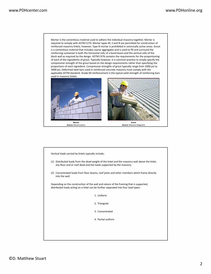
Mortar is the cementious material used to adhere the individual masonry together. Mortar is
required to comply with ASTM C270. Mortar types M, S and N are permitted for construction of
reinforced masonry lintels; however, Type N mortar is prohibited in seismically active areas. Grout
is a cementious material that includes coarse aggregates and is used to fill and surround the
reinforcing contained in both the horizontal cells of a bond beam and the vertical cells of the
block wall as required by the design. ASTM C476 contains the requirements for the proportioning
of each of the ingredients of grout. Typically however, it is common practice to simply specify the
compressive strength of the grout based on the design requirements rather than specifying the
proportions of each ingredient. Compressive strengths of grout typically range from 2000 psi to
3000 psi. Deformed steel bars used in reinforced concrete masonry must comply with the
applicable ASTM standard. Grade 60 reinforcement is the typical yield strength of reinforcing bars
used in masonry lintels.
Mortar
Source: Masonryworx
Grout
Source: Masonry Magazine
Vertical loads carried by lintels typically include;
(1) Distributed loads from the dead weight of the lintel and the masonry wall above the lintel,
any floor and or roof dead and live loads supported by the masonry.
(2) Concentrated loads from floor beams, roof joists and other members which frame directly
into the wall.
Depending on the construction of the wall and nature of the framing that is supported,
distributed loads acting on a lintel can be further separated into four load types:
1. Uniform
2. Triangular
3. Concentrated
4. Partial uniform

www.PDHcenter.com www.PDHonline.org
©D. Matthew Stuart
3
In some instances, the masonry wall will distribute loads so that they do not act on the lintel. This
is called arching action of masonry and is based on the amount of masonry that is above the
opening over which the lintel spans. The impact of distributed and concentrated loads on lintels is
affected by arching action. Arching action can be assumed if the following criteria are met:
1. The masonry is laid in running not stacked bond.
2. Sufficient wall height above the lintel exists to form a 45 degree triangle with at least 8
inches of wall height occulting above the top of the arch.
3. Minimum end bearing is maintained. For this last criterion it is important to recognize
that arching action results in horizontal thrust forces at the base of the arch. This thrust
must be accounted for in order for arching action to occur. Therefore it is not
recommended that arching action be assumed above openings that occur next to
corners of a building or at locations where the adjacent block at the bottom of the arch
is discontinuous.
As already indicated, the design loads applied to a lintel depend on whether arching action is
present or not. In the case of the weight of wall supported by a lintel, arching will cause only the
weight of wall within the triangular area below the top or apex of the arch to impact the lintel.
The triangular load has a base equal to the effective span length of the lintel and a height as
shown in this slide.

www.PDHcenter.com www.PDHonline.org
©D. Matthew Stuart
4
Concentrated loads are assumed to be distributed downwards at an angle of 30 degrees from the
vertical on each side of the point of bearing as shown in this slide.
The load is then resolved onto the lintel as a uniform load with a maximum length equal to four
times the wall thickness plus the width of bearing. The magnitude of the load per unit length is
computed by dividing the concentrated load by this same length: w=P/L. An example of the
impact of a concentrated load offset from a lintel opening is shown in the next slide.
Where: L = 4 x Wall Thickness + Width of Beam
w = P / L

www.PDHcenter.com www.PDHonline.org
©D. Matthew Stuart
5
In some cases a series of concentrated loads may be considered as uniform on a lintel. The
criteria as to whether a series of concentrated loads can be assumed as an equivalent uniform
load on the lintel is a function of the spacing of the loads. If this criterion is met the equivalent
uniform loading can be neglected if the bearing elevation of the beams occurs above any arching
action that is present. Otherwise, each concentrated load must be resolved into an equivalent
uniform load independently. As indicated in the previous slide, in some cases a series of
concentrated roof or floor loads on a wall laid in running bond may be considered as an
equivalent uniform load. This condition applies to relatively light loads spaced closely together
such as floor joists or roof rafters in residential or other similar construction. Concentrated loads
of these types may be considered as uniform as shown in the slide. In general these types of
concentrated loads can be considered as uniformly distributed if the total height of masonry
between the top of the lintel and the bearing elevation of the joists is at least 1/3 the center-to-
center spacing of the loads.
Heavier concentrated loads, such as that which may be encountered in industrial and commercial
buildings can also be considered to act as equivalent distributed loads as shown in this slide.
Where: SL is less than or equal to 4'-0"
www.PDHcenter.com www.PDHonline.org
©D. Matthew Stuart
6
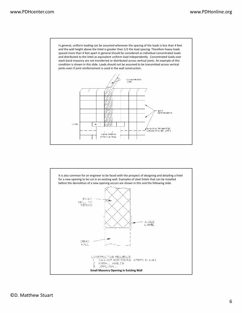
In general, uniform loading can be assumed whenever the spacing of the loads is less than 4 feet
and the wall height above the lintel is greater than 1/2 the load spacing. Therefore heavy loads
spaced more than 4 feet apart in general should be considered as individual concentrated loads
and distributed to the lintel as equivalent uniform load independently. Concentrated loads over
stack bond masonry are not transferred or distributed across vertical joints. An example of this
condition is shown in this slide. Loads should not be assumed to be transmitted across vertical
joints even if joint reinforcement is used in the wall construction.
It is also common for an engineer to be faced with the prospect of designing and detailing a lintel
for a new opening to be cut in an existing wall. Examples of steel lintels that can be installed
before the demolition of a new opening occurs are shown in this and the following slide.
Small Masonry Opening in Existing Wall
www.PDHcenter.com www.PDHonline.org
©D. Matthew Stuart
7
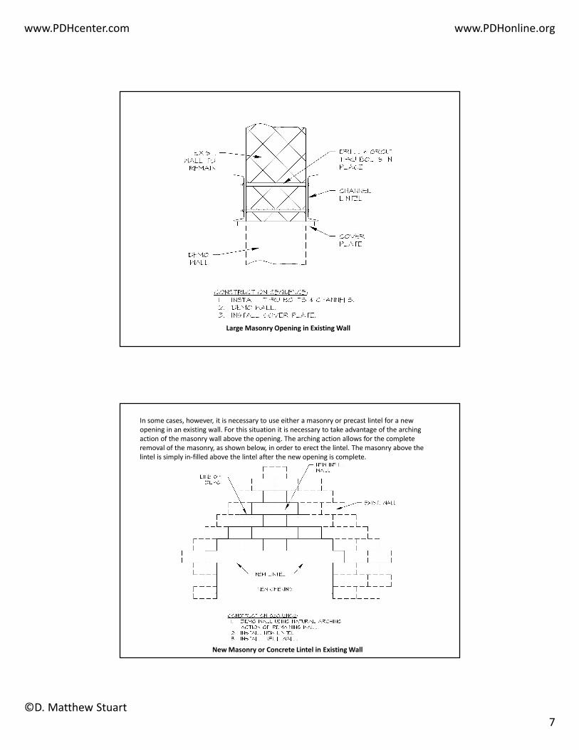
Large Masonry Opening in Existing Wall
In some cases, however, it is necessary to use either a masonry or precast lintel for a new
opening in an existing wall. For this situation it is necessary to take advantage of the arching
action of the masonry wall above the opening. The arching action allows for the complete
removal of the masonry, as shown below, in order to erect the lintel. The masonry above the
lintel is simply in-filled above the lintel after the new opening is complete.
New Masonry or Concrete Lintel in Existing Wall
www.PDHcenter.com www.PDHonline.org
©D. Matthew Stuart
8
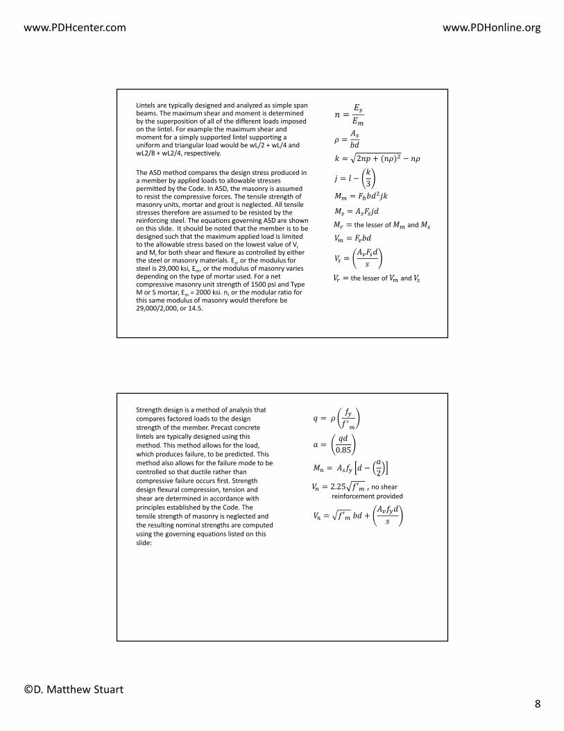
Lintels are typically designed and analyzed as simple span beams. The maximum shear and moment is determined by the superposition of all of the different loads imposed on the lintel. For example the maximum shear and moment for a simply supported lintel supporting a uniform and triangular load would be wL/2 + wL/4 and wL2/8 + wL2/4, respectively.
The ASD method compares the design stress produced in a member by applied loads to allowable stresses permitted by the Code. In ASD, the masonry is assumed to resist the compressive forces. The tensile strength of masonry units, mortar and grout is neglected. All tensile stresses therefore are assumed to be resisted by the reinforcing steel. The equations governing ASD are shown on this slide. It should be noted that the member is to be designed such that the maximum applied load is limited to the allowable stress based on the lowest value of Vr
and Mr for both shear and flexure as controlled by either the steel or masonry materials. Es, or the modulus for steel is 29,000 ksi, Em, or the modulus of masonry varies depending on the type of mortar used. For a net compressive masonry unit strength of 1500 psi and Type M or S mortar, Em = 2000 ksi. n, or the modular ratio for this same modulus of masonry would therefore be 29,000/2,000, or 14.5.
� =��
��
� =��
�
� = ��� ��
�� = ���
� = 2�� + (��) − ��
� = � −�
3
� = the lesser of � and �
�� =����
�
� = �����
�� = the lesser of �� and ��
Strength design is a method of analysis that
compares factored loads to the design
strength of the member. Precast concrete
lintels are typically designed using this
method. This method allows for the load,
which produces failure, to be predicted. This
method also allows for the failure mode to be
controlled so that ductile rather than
compressive failure occurs first. Strength
design flexural compression, tension and
shear are determined in accordance with
principles established by the Code. The
tensile strength of masonry is neglected and
the resulting nominal strengths are computed
using the governing equations listed on this
slide:
� = ���
� �
! = �
0.85
& = ���� −!
2
�& = 2.25 �′� , no shear
reinforcement provided
�& = �′�� +����
�

www.PDHcenter.com www.PDHonline.org
©D. Matthew Stuart
9
The requirements for the compressive strength of concrete, f’c, are designated in ACI 318. The
compressive strength of masonry, f’m, are found in ACI 530. Either of two methods is used to
verify compliance with f’m; the unit strength method or the prism test method. Of these two
tests, the unit strength method is more conservative and less expensive.
The allowable flexural stress for masonry lintels, Fb, is equal to 1/3 of f’m. The allowable shear
stress for masonry lintels is equal to the square root of f’m. For steel, in ASD, the allowable stress
is 24,000 psi for grade 60 reinforcing bars. To summarize:
�� =1
3�′�
�� = �′�
�� = 20,000 psi
Other important design parameters include the following:
• Reinforced concrete masonry strength design reduction factors for flexure and shear are
based on ACI 530 and are 0.8 and 0.6, respectively. Precast concrete strength reduction
factors are based on ACI 318 and are 0.9 for flexure and 0.85 for shear, even if you use
Appendix B and C of ACI 318-05.
• The effective span length of a lintel is defined as the clear span plus the depth of the
member but not greater than the distance measured between the support centers. ACI
530 states that end bearing should not be less than 4 inches. As an integral part of a
wall, lintels are typically considered as laterally supported. Lintel deflection is limited to
the effective span divided by 600 or 0.3” when used to support unreinforced masonry
per ACI 530. The commentary of this same Code waives the L/600 criterion if the
supported wall is considered reinforced masonry.

www.PDHcenter.com www.PDHonline.org
©D. Matthew Stuart
10
The effective compressive width, b, of a lintel should be taken as the nominal width less 3/8”. For
example, you should use 7-5/8” as the actual width of an 8” CMU block. The effective depth, d, is
also taken as the nominal depth less 3/8”. The depth of cover and half the diameter of the
reinforcing bar should also be subtracted from this depth. Limitations on reinforcing bars as
placed in masonry bond beams is shown in this slide. With a 1-1/4” face shell and a minimum
concrete cover of 3/4”, typically 2” of cover should be assumed for all reinforcement.