the design of optical fiber transmission system based on dcdm
TRANSCRIPT
The Design of Optical Fiber Transmission System Based on DCDM
Bai Shilei, Chen Cuizhu, Duan Zhonghang, Wang Ruidong, Zhang Zhen College of Information Engineering, Communication University of China, Beijing 100024, China
Abstract - In this paper,we introduce a new technology named Duty Cycle Division Multiplexing(DCDM) which realizes multiplexing by assigning each user a different RZ duty cycle. Multiplexing and demultiplexing principle of DCDM are analyzed. And we design demultiplexer of DCDM system using Matlab. In order to verify the feasibility of DCDM, Here we have designed a optical fiber transmission system which is based on DCDM of three users by Joint simulation with Optisystem and Matlab.And simulation result shows the feasibility of the system.
Index Terms - DCDM, Multiplexing, demultiplexer, MATLAB.
I . Introduction
Multiplexing technology is a technology that allows multiple users to share one signal transmission channel to improve the transmission performance of optical fiber communication system .In existing systems.the most commonly used Multiplexing technique in practice are Wavelength Division Multiplexing (WDM),Time-Division Multiplexing(TDM), or code-division multiplexing (CDM).
Even though WDM contributes grate efficiency, it is still quite far to get the electrical communication systems efficiency.In WDM systems, only one user can transmit data over a single carrier. In TDM systems,different users share a single optical carrier by signing each user at different time slot, resulting shorter pulse width.Thus, a high speed multiplexer and demultiplexer is required for TDM systems. And very high speed electronic component is required for multiplexer circuits, which results in a complicated and costly system. ]1[
Realizing these problems, An new multiplexing technique is proposed in this paper named duty cycle division multiplexing(DCDM), It based on Return-to-Zero (RZ) duty cycles and realized by different users assigned different RZ duty cycles .in this communication system where multiple data streams are transmitted simultaneously through a single fiber. This technique can be implemented in both wireless and wired communication systems, and it allows for better clock recovery. Here we have designed a optical fiber transmission system which based on DCDM of three users by Joint simulation of Optisystem and Matlab,And simulation result shows the feasibility of the DCDM system.
II . Working Principle
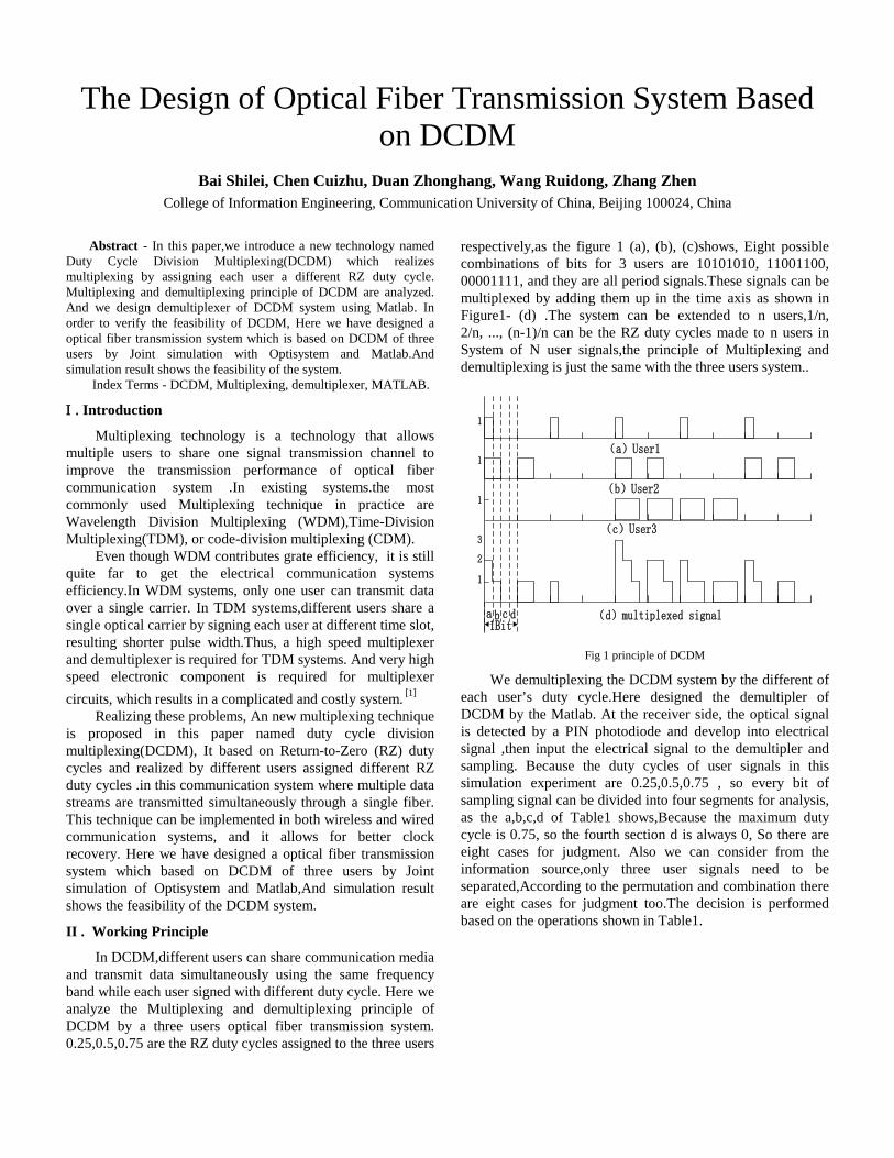
In DCDM,different users can share communication media and transmit data simultaneously using the same frequency band while each user signed with different duty cycle. Here we analyze the Multiplexing and demultiplexing principle of DCDM by a three users optical fiber transmission system. 0.25,0.5,0.75 are the RZ duty cycles assigned to the three users
respectively,as the figure 1 (a), (b), (c)shows, Eight possible combinations of bits for 3 users are 10101010, 11001100, 00001111, and they are all period signals.These signals can be multiplexed by adding them up in the time axis as shown in Figure1- (d) .The system can be extended to n users,1/n, 2/n, ..., (n-1)/n can be the RZ duty cycles made to n users in System of N user signals,the principle of Multiplexing and demultiplexing is just the same with the three users system..
(a)User1
(b)User2
(c)User3
(d)multiplexed signala b c d1Bit
1
1
1
1
2
3
Fig 1 principle of DCDM
We demultiplexing the DCDM system by the different of each user’s duty cycle.Here designed the demultipler of DCDM by the Matlab. At the receiver side, the optical signal is detected by a PIN photodiode and develop into electrical signal ,then input the electrical signal to the demultipler and sampling. Because the duty cycles of user signals in this simulation experiment are 0.25,0.5,0.75 , so every bit of sampling signal can be divided into four segments for analysis, as the a,b,c,d of Table1 shows,Because the maximum duty cycle is 0.75, so the fourth section d is always 0, So there are eight cases for judgment. Also we can consider from the information source,only three user signals need to be separated,According to the permutation and combination there are eight cases for judgment too.The decision is performed based on the operations shown in Table1.

Table1 The theory of demultiplexing
a b c Output1 Output2 Output3
0 0 0 0 0 0
1 1 1 0 0 1
1 1 0 0 1 0
2 2 1 0 1 1
1 0 0 1 0 0
2 1 1 1 0 1
2 1 0 1 1 0
3 2 1 1 1 1
We can get a sequence of binary signals when the input
signal is sampled,each bit signal is composed of a lot of
sampling signals. The simulation is sampled 64 times per
bit,but the resulting sampling signals too much to decision. So
one bit sampling signals according to the above needs to be
divided into four groups,and each group has 16 sampling
points, for the transmission loss and distortion, only kept the
eight sampling points in the middle and removed the first and
the last four sampling points in each group,it get the average
value of each group by divide eight,so each bit signal only has
four signal values.Then the signals had been normalized
according to the actual situation,So each bit signals have the
corresponding four values a, b, c, d.then the output signals can
be decision by according to the principle of table1.
Demultiplexing will be relatively complex for a system
with n users , but the principle of demultiplexing is the
same.First we should sampling to the input signals, and the
multiplexed signal should be sampled more than 5n times per
bit in system of N users. The sampling points of each bit is
divided into n group,then get the average value of each
group ,there are 2n
possible combinations of bits for n
users,and it can be demultiplexed by the same theory.
III. Simulation Study
A . The demultiplexer design of DCDM
The core of DCDM system is the design of
demultiplexer,we designed the demultiplexer of DCDM by
Matlab,The flow chart of the design is shown in Figure2
Input signal
Samplingsignal
sampling Every bit of sampling signal divide into four
groups and for the average
Signal normalization
judgmentUser1
User2
User3output output
output
Fig 2 The flow chart of demultiplexing
In the simulation, the number of the total sampling points
is set to be 8192.The sampling points of one bit is 64, the
number of the total sampling bits is 128, and the bit rate is
1000bit/s.Every 64 sampling points are divided into four
groups and each groups are averaged. Because the
corresponding average value is not always the same, so them
need to be normalized.For example, assign the signal values
which near "0" to "0" ,assign the signal values which near "1"
to "1" ,assign the signal values which near "2" to "2".In actual
situation,the amplitude of the signal received by the end will
be decayed,in this simulation, the received multiplexed signal
is shown in Figure 3:
Fig 3 the received multiplexed signal
Through the experiment we can see the eye diagram of
the input multiplexed signal and the eye diagram of the
multiplexed signal transmitted by the optical fiber and
received at the end as shown in Figure 4-1 and Figure 4-2,the
two eye is just distorted in the amplitude
(1)the eye diagram of the input multiplexed signal
(2)the eye diagram of the received multiplexed signal
Fig 4 the eye diagram
337

So the signal averages are in the vicinity of the 0,0.054,
0.156, 0.21 and not greater than 0.01 are normalized into
0,1,2,3 which are corresponding to the above a,b, c,
d.According to the decision principle table1, the signal can be
separated,the separated signal is the binary signal,through the
zero signal generator we can get original signal before
multiplexed ,Compare the signals shown in Figure 5-2 and
Figure 5-1,we can see that they are the same,which shows the
feasibility of the DCDM system.
(a)User1 (b)User2 (c)User3
Figure 5-1 The original signal
a b c
Figure 5-2 The demultiplexed signal
B . Design of simulation system
The simulation diagram as shown in Figure 6
Fig 6 The simulation diagram
IV . Conclusion
In this paper, we introduce a new technology named Duty
Cycle Division Multiplexing (DCDM) ,and designed a optical
fiber transmission system which is based on DCDM of three
users by Joint simulation with Optisystem and Matlab.In the
simulation,the obtained demultiplexed signals and the original
signals are consistent,so it verified the feasibility of DCDM in
optical fiber transmission system.This technique can be
implemented in both wireless and wired communication
systems,and it allows for better clock recovery,and it can also
increase the dispersion tolerance.The multiplexing technology
is only suitable for the RZ signal,and this is the limitation of
the DCDM, so the technology still needs further research
before being used in practical applications.
References
[1] G. A. Mahdiraji, A. M.Mohammadi, A. F. Abas, M.K. Abdullah,
M.Mokhtar.A Novel and Economical Optical Multiplexing and
Electrical Demultiplexing technique for High Speed Fiber
Optics Networks.2008 International Conference on Electronic
Design.
[2] Avinash Singh, Gireesh G. Soni, Abhishek Tripathi and Anurag
Shrivastava .Design of 3×60 Gbps DCDM based WDM
system . International Conference on Optical Engineering
(ICOE) 2012.
[3] A. Malekmohammadi,M.K. Abdullah,G.A. Mahdiraji,A.F.
Abas,M. Mokhtar,M.F.A. Rasid,S.M. Basir .Analysis of return-
to-zero-on-off-keying overabsolute polar duty cycle division
multiplexing in dispersive transmission medium. IET
Optoelectronics,doi: 10.1049/iet-opt.2008.0050.
[4] A.Lord, L.C.Blank, J.M.Boggis, W.A.Stallard, E.G.
Bryant.Optical multiplexing techniques for future Gbit/s
transmission systems.IEEE International Conf. on
Communication. (ICC), vol. 1, pp. 21-25, (1988).
338