the design and implementation of intermediate codes for...
TRANSCRIPT

The Design and Implementation of IntermediateCodes for Software Visualization
Andrés Moreno García
2005-01-02
University of JoensuuDepartment of Computer ScienceMaster’s Thesis

Resumen
Esta tesis es parte del proyecto Jeliot 3. El fin del proyecto es crear una herramienta
modular para visualizar la ejecución de programas escritos en Java. El diseño de la
herramienta debe permitir que ésta sea fácilmente ampliable. La visualización ha de
ser similar a la mostrada por la herramienta precedente, Jeliot 2000 (Ben-Bassat Levy
et al., 2003), pero incrementando el número de características animadas, con especial
énfasis en animar programas orientados a objetos.
Esta tesis presenta el código intermedio usado en Jeliot 3, el MCode. MCode es un
código que representa la ejecución de un programa. MCode es generado por un in-
térprete del lenguaje a animar, en nuestro caso DynamicJava (Koala Project, 2002).
MCode es puesto a disposición de diferentes intérpretes para crear diferentes anima-
ciones a partir del mismo código. Esto es posible porque MCode sólo expresa infor-
mación semántica, en lugar de gráfica.
Por último, esta tesis intenta clasificar y crear una taxonomía de los diferentes códigos
intermedios y de los lenguajes usados en el campo de la "Visualización del software"
(Software Visualization). Para ello se han revisado diez sistemas o lenguajes; desde el
lenguaje intermedio de cuartetos propuesto por Aho et al. (1986), hasta los puramente
gráficos como Jawaa (Pierson and Rodger, 1998) y Animal (Rößling et al., 2000).
El desarrollo de la taxonomía permitío observar como los diferentes códigos interme-
dios proporcionan un eqilibrio entre las posibilidades para ser personalizado y para ser
reusado. Por ejemplo, la generación de MCode depende exclusivamente del intérprete
que lo genera, sin poder ser modificado, sin embargo, puede ser reusado con libertad.
2

Abstract
Software systems make use of intermediate codes to translate one problem into another
one manageable by the system. Software Visualization systems have also followed this
principle. We have reviewed SV tools and built a taxonomy based on their implemen-
tation aspects. Most tools provide advanced technical solutions to animate one single
concept. But most of them fail to provide ways to extend themselves. A good tech-
nical solution cannot be reused, because it cannot be adapted to different teaching
approaches. Jeliot 3 is a Program Visualization tool that has been designed with ex-
tensibility in mind. MCode is an intermediate code that represents the execution of a
program. It is generated by an interpreter and it is made available to different inter-
preters. These interpreters can produce different visualizations of the same program.
It is possible because MCode only conveys semantical information about the running
program rather than graphical. Semantical information can be reinterpreted satisfacto-
rily. Finally, the design of MCode eases the addition of new instructions that can extend
the learning capabilities of Jeliot 3 beyond the simple program execution animation.
ACM-Classification (ACM Computing Classification System, 1998 version): K.3.2
[Computers and Education]: Computer and Information Science Education –Com-
puter Science Education; D.2.5 [Software Engineering]: Testing and Debugging –
Tracing; D.3.4 [Programming Languages]: Processors –Code generation, Inter-
pretersH.5.1 [Information Interfaces and Presentation]: Multimedia Information
Systems –Animations; I.6.8 [Simulation and Modeling]: Types of Simulation –Ani-
mation, Visual
Keywords:Software Visualization, Program Animation, Jeliot 3, Novice Programmers

List of Publications
Paper I Andrés Moreno and Niko Myller, “Producing an Educationally Effective and
Usable Tool for Learning, The Case of the Jeliot Family”.In Proceedings of
International Conference on Networked e-learning for European Universities,
Granada, Spain 2003, CD-ROM.
Paper II Andrés Moreno, Niko Myller and Erkki Sutinen, “Collaborative Program
Visualization with Woven Stories and Jeliot 3”.In Proceedings of the IADIS
International Conference on Web Based Communities, Lisbon, Portugal, 2004,
pp. 482–485.
Paper III Andrés Moreno, Niko Myller, Erkki Sutinen and Moderchai Ben-Ari, “Vi-
sualizing Programs with Jeliot 3”.In Proceedings of the International Working
Conference on Advanced Visual Interfaces AVI 2004, Gallipoli, Italy, May, 2004,
pp. 373–376.
Paper IV Osku Kannusmaki, Andrés Moreno, Niko Myller, and Erkki Sutinen, “What
a Novice Want: Students Using Program visualization in Distance Programming
Course”. In Proceedings of the Third Program Visualization Workshop. War-
wick, UK, 2004, pp. 126–132.
Paper V Andrés Moreno, Niko Myller and Erkki Sutinen, “JeCo, a Collaborative
Learning Tool for Programming”.In Proceedings of the IEEE Symposium on Vi-
sual Languages and Human-Centric Computing, Rome, Italy, September, 2004.
i

Preface
It has been more than two years I have been involved in the Jeliot 3 project. It all began
in 2002 when I arrived to Joensuu as an Erasmus student. Erkki Sutinen opened me
the door to Finland and offered me a reason to stay here. He and his family has been
my reference during all this time, both academically and personally. And I am really
thankful to them and to their kindness and hospitality.
I would like to thank, as well, the “Israeli team”. Moti Ben-Ari and Ronit Ben-Bassat
Levy have visited Joensuu and it has been a pleasure to meet them. Moti has been
guiding and pushing for my thesis to come to a happy end. Ronit has been the constant
colleague and, most important, dear friend that has supported me when I needed. I
wish the best to both of you and I hope to meet you soon.
I have no words to thank Niko Myller. All I can say is that he has been the most
important person in Finland during these 2 years. He has always been there when I
needed, and when I did not. Jeliot 3 is still part of our lives and we will not miss those
long bug-hunting nights. Thanks
These two years in a foreign land, I have met lots of different people. But fate and luck
had led me to gather an impressive set of friends. To all of them, I just wish that time
will make our bonds stronger.
Finally, my family. I dedicate this work to all of you. My parents, for everything
they have done through the years and offering me the possibility to study abroad; my
brothers, because we have already walked together a long distance, and we are ready
to be together till the end.

Contents
1 Introduction 1
1.1 Why is Jeliot 3 needed? . . . . . . . . . . . . . . . . . . . . . . . . . 1
1.2 Why Is an Intermediate Code Needed? . . . . . . . . . . . . . . . . . 2
1.3 Why a Taxonomy? . . . . . . . . . . . . . . . . . . . . . . . . . . . 3
1.4 Thesis’ overview . . . . . . . . . . . . . . . . . . . . . . . . . . . . 3
2 Literature Review 4
3 Jeliot 3 8
3.1 Overview . . . . . . . . . . . . . . . . . . . . . . . . . . . . . . . . 8
3.1.1 History . . . . . . . . . . . . . . . . . . . . . . . . . . . . . 8
3.1.2 Jeliot 3’s User Interface . . . . . . . . . . . . . . . . . . . . 12
3.1.3 Jeliot 3’s System Structure . . . . . . . . . . . . . . . . . . . 13
3.2 Description of Jeliot 3’s graphical features . . . . . . . . . . . . . . . 15
4 Taxonomy of Intermediate Codes 17
4.1 Method . . . . . . . . . . . . . . . . . . . . . . . . . . . . . . . . . 17
4.2 Characterization of Software Systems . . . . . . . . . . . . . . . . . 17
4.2.1 Aho’s Intermediate Code Generation . . . . . . . . . . . . . . 18
4.2.2 Pascal and P-code . . . . . . . . . . . . . . . . . . . . . . . 18
4.2.3 Java and Java Bytecode . . . . . . . . . . . . . . . . . . . . . 20
4.2.4 Dynalab and E-machine . . . . . . . . . . . . . . . . . . . . 22
4.2.5 Leonardo Visualization System . . . . . . . . . . . . . . . . 23
4.2.6 Javavis . . . . . . . . . . . . . . . . . . . . . . . . . . . . . 26
4.2.7 Jawaa and Animal . . . . . . . . . . . . . . . . . . . . . . . 27
4.2.8 Viz . . . . . . . . . . . . . . . . . . . . . . . . . . . . . . . 29
4.2.9 PVML . . . . . . . . . . . . . . . . . . . . . . . . . . . . . 30
4.2.10 Jeliot 3 and MCode . . . . . . . . . . . . . . . . . . . . . . . 33
iii

4.3 Classification . . . . . . . . . . . . . . . . . . . . . . . . . . . . . . 33
4.3.1 Taking into Account Price’s Taxomomy . . . . . . . . . . . . 34
4.3.2 Extending Price’s Taxonomy . . . . . . . . . . . . . . . . . . 34
4.3.3 Getting All Together . . . . . . . . . . . . . . . . . . . . . . 36
5 MCode explained 39
5.1 Definition of MCode . . . . . . . . . . . . . . . . . . . . . . . . . . 39
5.2 MCode in Jeliot 3 . . . . . . . . . . . . . . . . . . . . . . . . . . . . 39
5.3 MCode Specification . . . . . . . . . . . . . . . . . . . . . . . . . . 40
5.4 MCode Details . . . . . . . . . . . . . . . . . . . . . . . . . . . . . 41
5.5 Generating MCode . . . . . . . . . . . . . . . . . . . . . . . . . . . 43
5.5.1 DynamicJava . . . . . . . . . . . . . . . . . . . . . . . . . . 43
5.5.2 MCode Production . . . . . . . . . . . . . . . . . . . . . . . 44
5.6 Interpreting MCode . . . . . . . . . . . . . . . . . . . . . . . . . . . 50
5.7 MCode Examples . . . . . . . . . . . . . . . . . . . . . . . . . . . . 51
5.7.1 Procedural Program . . . . . . . . . . . . . . . . . . . . . . 51
5.7.2 Object-oriented Program . . . . . . . . . . . . . . . . . . . . 54
6 Discussion and Conclusion 58
6.1 On MCode . . . . . . . . . . . . . . . . . . . . . . . . . . . . . . . 58
6.2 On Taxonomy . . . . . . . . . . . . . . . . . . . . . . . . . . . . . . 58
6.3 FutureWork . . . . . . . . . . . . . . . . . . . . . . . . . . . . . . . 59
Bibliography 61
Appendix 1
A Intermediate Code Specification 1
iv

Chapter 1
Introduction
This thesis is part of the ongoing Jeliot 3 project. This project tries to develop a modular
program visualization tool that can be easily extended. It aims also to explain object
oriented concepts by means of visualization paradigms that integrate with the previous
paradigms used in Jeliot 2000 (Ben-Bassat Levy et al., 2003).
The thesis introduces the intermediate code used in Jeliot 3, theMCode. MCode is
explained in depth and compared with other similar approaches. Further development
of MCode, or applications using it, should refer to this thesis and the Appendix A.
This thesis aims to classify the different intermediate codes and scripts used in Software
Visualization as well as those used in real and in formal compilers, as described by Aho
et al. (1986).
1.1 Why is Jeliot 3 needed?
Jeliot 3 is a program animation tool. Program Animation is a a subdiscipline of the
Software Visualization field. Software Visualization tries to represent software sys-
tems in ways that helps the user, developer, or student, to understand it. Jeliot 3 dis-
plays how a Java program is executed in an exposed virtual machine. Everything that
happens inside the virtual machine is animated and the correspondent source code is
highlighted.
Jeliot 3 is the result of the re-implementation and extension of Jeliot 2000 in order to
1

achieve further goals after assuring the usefulness of Jeliot 2000. Ben-Bassat Levy
et al. (2003) suggested a way to use Jeliot 2000 that was beneficial for novice students,
especially those who showed mediocre scores in the beginning. The main goals that
were set up in the beginning of the development of Jeliot 3 were the following:
• Modular design. The system should be extensible both internally and externally.
Allowing the system to be internally extensible we guarantee that future require-
ments will not imply a complete redesign. The possibility of getting aid from
developers is easier to support with a good external extensibility. Developers
can program their own extensions to the system improving the final product.
• Object oriented features. The system should support the visualization of an
as large as possible subset of Java programs. Currently, the object-oriented
paradigm is part of many introductory programming courses. Despite being
closer to human reasoning than procedural programming, it has been shown that
fundamental concepts such as inheritance, generalization and encapsulation are
still hard to grasp. In order to make Jeliot useful in those courses, support for
object oriented concepts is needed.
1.2 Why Is an Intermediate Code Needed?
An intermediate code allows the modularity of the software, establishing the bound-
aries between the code interpreter and the proper animation generator. Myller (2004)
explains in further detail the reasons behind the “decomposition” of the tool in its sep-
arate parts.
However, the MCode makes possible a new range of applications. On one hand, it sets
a standard language understood by the animation generator, or visualization engine,
thus different language interpreters could produce valid MCode that can be rendered
by the same director. On the other hand the same intermediate code can be rendered
into animation by means of different directors that understand the MCode.
2

1.3 Why a Taxonomy?
There are already different taxonomies on Software Visualization: Price et al. (1993),
Brown (1988b), Stasko and Patterson (1992), Myers (1986, 1990). These taxonomies
focus mostly on describing the visual properties and visual capabilities, rather than
describing the technical implementations used to achieve it. With this thesis we try to
cover that point. Thus we provide a taxonomy of the approaches taken to implement
the different Software Visualization tools and compare them to the solutions taken by
programming languages compilers.
1.4 Thesis’ overview
The thesis is divided in five more chapters. Chapter 2 introduces similar work done
both in the field of Software Visualization tools and in the different taxonomies of the
field. Chapter 3 introduces Jeliot 3, it summarizes Myller (2004) in order to understand
the environment where MCode belongs to. Before describing MCode in Chapter 5,
Chapter 4 includes a taxonomy of systems that have made use of intermediate code or
that are similar to Jeliot 3. Conclusions and discussions of this work can be found in
Chapter 6.
3

Chapter 2
Literature Review
Related Work
Jeliot 3 is not the only program that helps students to learn programming, more con-
cretely in Java. The most widely used system isBlueJ(Kölling and Rosenberg, 2001).
BlueJ is a project manager oriented for novices. It shows the class diagrams and main-
tains anobject bench. The object bench is a useful idea. Students can instantiate
objects one by one, and they will be placed in the bench for future use. For example,
after objects are created, their fields can be accessed and their methods can be called.
DrJava (Allen et al., 2002) orjGRASP(II et al., 2002) are also interesting tools that
try to make learning Java easy. DrJava is intended to help students with their first
programming projects. It also uses DynamicJava, a Java interpreter, like Jeliot 3 does
(see Section 5.5), but for DrJava it serves as a dynamic interpreter that can be used to
test the already implemented classes. jGRASP aims to ease the use of a debugger to
novices when they start with object oriented concepts. Another Java teaching tool is
ProfessorJ(Gray and Flatt, 2003). It provides a simple environment to implement Java
programs similar to the one in DrJava. Its most remarkable feature is its adaptability.
The set of Java language allowed constructs and compiler error messages are adapted
to the declared user knowledge. Finally, Javavis (Oechsle and Schmitt, 2002) is a tool
oriented for novices that emphasizes visualization (see Section 4.2.6).
4

Taxonomies
Many different taxonomies have been proposed for the field of Software Visualization
(SV) and Program Visualization (PV). They pursue to sort the field and to open new
directions for research. The five most important taxonomies are Myers (1986, 1990),
Brown (1988b), Stasko and Patterson (1992), Roman and Cox (1993) and Price et al.
(1993).
Myers (1986) outlined the first taxonomy of Software Visualization Tools and revised
later (Myers, 1990). He classified Software Visualization tools under two simple cate-
gories.
• What they animate -aspect: code, data or algorithms.
• How they animate it -display style: static or dynamic.
This was the seminal work for future taxonomies; Stasko and Patterson (1992) and
Price et al. (1993) extended Myers’ taxonomy. Stasko and Patterson (1992) added two
more properties to Myers’ taxonomy:
• Abstractness: It describes how close the visual representation of a concept is to
that concept. For example, if a boolean variable were represented like a text tag
(“true” or “false”), its abstractness would be quite low. If it were represented
like a switch, with on and off states, its abstractness would be higher than in the
previous case.
• Automation: It describes the level of automation, e.g. the degree of user effort
needed to produce the visualization.
Price et al. (1993) constructed a taxonomy in a more structured way than previous
works. Its six main categories are deduced by reducing every SV tool to a black box.
Further subcategories are derived from these 6 main categories in a hierarchical way,
to sum up a total of 53 subcategories. The six main categories are:
• Scopedescribes what kind of software can be accepted by the tool -the input to
the black box. Systems can be useful for only one programming language, or
only for small toy programs.
5

• Content: The subset of the scope that is actually visualized. For example, one
tool will focus only in method calls, while another one can only visualize the
data containers.
• Form describes the properties of the visualization -the output of the black box.
The output can be displayed in paper, video or a graphical workstation. Each
kind of medium can have different properties, as animation, position or sound.
• Methoddescribes how the visualization tool works, how the animation and visu-
alization is produced—the internals of the black box (see Section refsec:Classification).
• Interactiondescribes the way user can interact with the system. And how the user
can modify its behavior. It will enumerate some used techniques as zooming,
selectivity and abstraction.
• Effectivenessmeasures how close the proposed goals and basic properties (e.g
clarity and goodness) are met. It also reports the evaluation and actual usage of
the tool.
Price’s taxonomy is designed to allow the inclusion of new subcategories. Yehezkel
(2002) has adapted and extended it to represent more faithfully computer architecture
visualizations.
The taxonomy of Roman and Cox (1993) also approached the classification in a struc-
tured way. They defined Program Visualization as a mapping from programs to graph-
ical representations. They extracted three roles from the definition, theprogrammer
who writes the program to be visualized, theanimatorwho defines and constructs the
mappings, and theviewerwho actually uses the visualization. The definition and the
roles are the basis for the six proposed categories.
• Scope: Like in Myers (1990), the aspect of the program visualized by the tool.
• Abstractiondescribes the level of abstractness of the visualization, from simple
highlighting to complex graphs describing different properties.
• Specification Methoddescribes how the mappings are specified. Similar to Stasko’s
automation. It is also similar to Price’smethodproperty. However, Price’s prop-
erty is more detailed than Roman and Cox’s one.
6

• Interfacerelates to the mechanisms the system has to let the viewer cope with
the visualization. Similar to Price’sinteractionproperty.
• Presentationis a property related to the animator or visualizer and the way he
produces the animation. Roman emphasized the importance of the message
rather than the appearance of it.
Brown (1988b) described three axes in his taxonomy. Brown focused on the visual
properties of animations, and how Balsa-II (Brown, 1988a) performed in the different
categories. Animations can be classified under the following properties:
• Content: Roman and Cox’sabstractionproperty was inspired by this one and
they are quite similar. Brown only differentiated between direct and synthetic
representations, but Roman included structured representation that Brown pre-
ferred to classify in the direct category.
• Persistence: This property describes how long the information stays on display.
From those that only show the current state to those that keep a history of data
or events.
• Transformation: It describes the method of changing the information on the dis-
play. It will be incrementalif the changes are animated smoothly ordiscrete
otherwise.
All these taxonomies have been of great help to locate and improve the different tools.
However, despite of being around for a long time, most of the open questions and
problems presented by the taxonomies remain unsolved. For examplePrice et al. (1993)
found out that one of the most missed features in current visualization tools was the
ability to switch between an algorithm-level animation and a program-level animation.
We believe that with a correct intermediate code it is possible to implement such a
switch with ease.
7

Chapter 3
Jeliot 3
3.1 Overview
This section gives an overview on Jeliot 3. It summarizes Myller (2004) and the inter-
nal documentation on Jeliot 3 (Moreno and Myller, 2003). Niko’s thesis describes the
design of Jeliot 3 and the reasons behind the decisions made during its development
process. This chapter and the thesis provide a background of Jeliot 3, needed for a
better understanding of the MCode.
3.1.1 History
Jeliot 3 belongs to a family of visualizations tools, known as the Jeliot family. This
family comprises four different tools: Eliot, Jeliot I, Jeliot 2000 and Jeliot 3. We can
split the family into two main branches: the one oriented to visualize data flow in al-
gorithms and the other one that visualizes the runtime behavior of programs, including
both data and control flow.
The Jeliot family is not only crowded, it has also been long-lasting. Since Eliot, the first
in the family, was developed more than ten years ago, when Erkki Sutinen and Jorma
Tarhio found a lack of easy-to-use tools to animate algorithms involving data types,
e.g. strings matching algorithms. Eliot provided a visual interface to edit the visual
appearance properties of some previously defined self-animated data types, see Fig-
ure 3.1. Eliot used the theater metaphor introduced in Halsa++ (Lahtinen et al., 1998)
8

and its related vocabulary in order to explain and assist the learning of its complicated
interface.
Figure 3.1: Eliot windows. The big main window let the user chose which variables
to animate. The other two are used to set up the visual properties of the animated
variables.
The theater metaphor describes the application by relating theater specific vocabulary
to the application internals. This way the program code that defines the algorithm
constitutes the script of the play. Like in every script there is a plot played by some
roles; by roles we mean the data contained in the data structures the algorithm makes
use of. However, a script and its roles are just a piece of paper, nothing people can
watch or interact with. To make that possible, a director must take the script and direct
some actors to represent its interpretation. In our case the director will interpret the
script, by choosing the roles she wants to appear on the stage, and how actors move on
the stage. The stage, then, is something real, what the audience will finally watch.
The director role can be assumed by a predefined computer algorithm, making the
program self-animating, or by the tool user, and thus making it manual, or by both, a
9

Figure 3.2: Main window of Jeliot I
semi-automatic visualization tool.
The theater metaphor has been used throughout the whole Jeliot family; for a detailed
explanation refer to Myller (2004).
Jeliot I (see Figure 3.2)was the follow-up application to Eliot. It tried to solve some
of the problems found in Eliot (Lattu et al., 2000). While Eliot ran as a native X
Window application, Jeliot I runs as a Java client-server applet. While Eliot animated
C programs, Jeliot I animates Java programs, thus the “J” in Jeliot I. Thanks to its
architecture, Jeliot I is available online, and any Java enabled browser can run it and
test it (Haajanen et al., 1997). Despite the huge improvement in accessibility Jeliot I
provides, it still poses problems to novices when trying to understand Java programs.
However, Jeliot I has been used in Data Structures Courses due to its self-animated
data types (Lattu et al., 2000).
The research performed with Jeliot I (Lattu et al., 2000) led to conclusions that pro-
vided the basis for the next generation, Jeliot 2000 (Ben-Bassat Levy et al., 2003). It
was found that Jeliot I was not suitable for novices. They could not understand the
logic behind the algorithms without a more detailed visualization of the program flow.
Moreover, the very detailed interface of Jeliot I made them get lost even before the
animation had started.
10

Figure 3.3: Jeliot 2000 window
Jeliot 2000 (see Figure 3.3) was developed by Pekka Uronen at the Weizmann Institute
of Science under the supervision of Mordechai Ben-Ari. Jeliot 2000 remained with
the theater metaphor, though modified. It was built from scratch to solve the problems
that arose in Jeliot I and to orient it towards the novice users. The interface was re-
duced to a single window, with VCR-like control buttons. The animation shifted its
focus from the data structures behind the program to the program itself: method calls,
loops, variables and expressions were fully animated. All these included features were
direct consequences of the premises that guided Jeliot 2000: the visualization must
becompleteandcontinuous(Ben-Bassat Levy et al., 2003). It is complete because it
animates every single step with a clear and stable semantic, so as to reduce the cogni-
tive load on the user. Continuous means that there is a clear relationship between the
current visualized event and the previous one. No intermediate step is omitted or made
implicit.
The usefulness of Jeliot 2000 was studied by Ben-Bassat Levy et al. (2003), who con-
cluded that Jeliot 2000 was really valuable to teach mediocre students or those who had
difficulties with understanding abstract concepts of programming. It also showed that
Jeliot 2000, with its predefined visualization behavior, provided a common language
between students and teachers. This common language helped students to explain bet-
11

Figure 3.4: Jeliot 3 window
ter their difficulties and to build basis for their programming knowledge.
Despite all these features, Jeliot 2000 came with some limitations due to its implemen-
tation. Java was not fully supported, not all operators and, more importantly, object-
oriented features were non-existent in Jeliot 2000. Jeliot 3, the latest member of the
Jeliot family, intends to overcome the limitations of Jeliot 2000 without changing the
reasons that led the development of Jeliot 2000. Jeliot 3 is the result of redesign-
ing Jeliot 2000 to provide a better framework for future development and incorporate
object-oriented support.
3.1.2 Jeliot 3’s User Interface
The design of Jeliot 3 was carefully thought out in order to avoid repeating the same
problems that appeared in Jeliot I and Jeliot 2000. However, Jeliot 2000’s improved
interface and graphical features were kept. The main work carried out was in the
implementation, see Section 3.1.3. As it can be seen Figure 3.1.2, Jeliot 3 resembles
Jeliot 2000 (Figure 3.3).
The interface is divided into two main parts. The editing panel consists of the editor
bar, containing the buttons to access the most used functions while editing. The editor
12

can be found below its button bar. The text editor has been enhanced, and it supports
syntax highlighting and brace-matching. The editor is blocked during the animation.
If we keep on moving down in the main window, we will reach the animation bar,
containing the buttons that control the animation, whether to start it, pause it, stop it,
or rewind it. The slider below them corresponds to the speed selector. The right side
of the window contains the theater, animation area, all the animation occurs there. The
theater is complemented by a console terminal that will print out the system output of
the animated program.
MethodFrameArea
ConstantsArea
InstanceArea
ExpressionEvaluation
Area
Figure 3.5: The structure of the animation frame (theatre) in Jeliot 3.
The theater (Figure 3.5) is divided into several areas. The placement of the areas
is unchanged during the whole animation process. However, the size of the areas is
dynamically changed to accommodate the new objects placed in them. In Jeliot 3,
the areas have been clearly differentiated by means of lines in between them and their
titles. Although its aim is to make the whole animation area clearer, it can also cause
misunderstanding as the process of animating one actor from one area to the other is
shown but the underlying reason is not explained.
3.1.3 Jeliot 3’s System Structure
As stated before, one of the main reasons of developing Jeliot 3 was to improve the
system structure and design. One of the keywords is modularity. The possibility to
13

add, either internally or externally, new features to the core of the application was
meant to be an important requirement. Fulfilling this requirement induced a modular
design, where new features can be added in an external module and, thus, not affecting
the behavior of other modules.
&%
'$
User
User interface
'
&
$
%
Source codeof the program
Interpretationof the program
'
&
$
%
Intermediatepresentation
of the programexecution
Visualizationengine
IntermediatepresentationInterpreter
6
?
6
1.
-2. -3.
?
4.
¾5.
-6.
-7.
@@
@@
@@
@I
8.
Figure 3.6: The functional structure of Jeliot 3. From Myller (2004).
From Myller (2004):
The structure of Jeliot 3 is shown in 3.6. The user interacts with the user
interface and creates the source code of the program (1). The source code
is sent to the interpreter and the intermediate code is extracted during the
execution of the code (2 and 3). The intermediate code is interpreted and
the directions are given to the visualization engine (4 and 5). The user
can control the animation by playing, pausing, rewinding or playing step-
by-step the animation (6). Furthermore, the user can give input data, for
example, an integer or a string, to the program executed by the interpreter
(6, 7 and 8).
This thesis takes into account the steps 2 and 3 and their related states and compare
them with different approaches.
14

3.2 Description of Jeliot 3’s graphical features
This section will explain the graphical features that used in animation in Jeliot; it is
recommended to examine one of them before reading this section. An example of an
animation is shown in Figure 3.7. Seven different phases of a class allocation are dis-
played. First,new Side() is shown, marking the beggining of the class allocation.
In 2 and 3, the object and its field are created. The next frame shows the constructor
frame with the reference to the object just created. In frame 5, field initialization is
shown. The reference of the object is then returned as the result of the constructor.
Finally, the reference to the object is assigned to the fieldw.
The animation background consists of a canvas or main stage. Actors, in our case
boxes, that can contain values, operators, messages or other actors, move around the
stage describing the execution of the program. The animation starts with one actor of
the type static method call invoking the main method of the program. This one and the
rest of the method calls will be shown in Expression Evaluation Area. The invocation
of a method produces a new method frame in the Method Frame Area. Method frames,
an example of a compound actor containing several actors, contain a title, with the
name of the method and a list of actors that hold the values for the local variables to
that method in a UML fashion.
Input instructions are displayed as a box-shaped actor in the Expression Evaluation
Area, where users can type in the value they are asked for. Values contained on actors
are animated smoothly from their original place in the theater to where they are needed
during the animation. These animations are used to form expressions or to reflect an
assignment.
References to objects and arrays are shown with arrows from the corresponding value
actors to the actual object in the Object and Array Area. Access to an array element is
visualized with a line from the value actor containing the index to the corresponding
element in the array.
The source code listing takes part in the visualization as well. During the animation
the editor is disabled and the director takes control of it. The source code of the current
animated step is highlighted in the editor window. Thus, users can follow the execution
in both views, in the source code view and in the animation frame.
15

1 2
3 4
5 6
7public class Side { public int length; Side(){ length=0; }}
public class Square{ Side w,h; Square(){ w = new Side(); h = new Side(); }}public class MyClass { public static void main() { Square square = new Square(); }}
1
23
45
6
7
Figure 3.7: Different phases of a Jeliot 3 animation.
16

Chapter 4
Taxonomy of Intermediate Codes
4.1 Method
The taxonomy is explained after ten systems have been reviewed. These ten systems
help to explain better the choices of categories and the different possible attributes of
the categories. The ten systems have been chosen by their particular architecture and
its relation with Jeliot 3.
4.2 Characterization of Software Systems
Subsections 4.2.1, 4.2.2 and 4.2.3 introduce the intermediate code used by compilers.
These intermediate codes generated are meant to be executed by a target machine,
sometimes a virtual machine. They show how previous “mainstream” efforts have
been taken into account when developing new visualization tools.
Subsections 4.2.4 and 4.2.5 introduce two systems that use their own virtual machine
to dynamically generate the animation. Both machines feature the possibility of going
backwards.
Subsection 4.2.6 presents a system that visualizes a program interpreting the events
fired by the JVM.
Subsection 4.2.7 explains two different scripting languages used to generate anima-
17

tions. These scripts can be created by hand, as the result of executing a program, or
with a graphical editor.
Subsections 4.2.8, 4.2.9 and 4.2.10 present three intermediate codes that trace the exe-
cution of a program.
4.2.1 Aho’s Intermediate Code Generation
Intermediate codes are used in everyday compilers to ease the creation of compilers
for different architectures. It is the last representation of the source code before opti-
mization and machine code generation.
A good description of different intermediate codes can be found in Aho et al. (1986).
Instructions usually consist of an operator, and references to other instructions, that
will act as the operands.
The intermediate code, as well as the obtained machine code, is not a representation of
the execution of a program or trace, but just a more concrete, or low level, representa-
tion of the program.
Quadruplesconsist of an operator, two arguments and the place where to store the re-
sults; these three last operands are memory references that will change during compile
time. For example, Figure 4.1 represents the quadruples corresponding to the code
x = a + 3 * c .
r1 := 3
r2 := r1 * c
x := a + r2
Table 4.1: Quadruples, where x, a, r1 and r2 are registers.
In Section 5.4 a comparison between Aho’s intermediate code and MCode is described.
4.2.2 Pascal and P-code
The Pascal language was developed by Jensen and Wirth (1974) atETH, Zurich. Pascal
was designed as a completely structured programming language, focusing more in
18

the readability rather than optimization; teaching programming is its primary field of
application. However, it gained some momentum and was used also as a commercial
programming language.
One of the developed compilers for Pascal was Pascal-P (Nori et al., 1981). The
Pascal-P, or P, compiler presents a set of features that makes it an interesting com-
piler. The most interesting feature is its design that aims to ease portability. This goal
was achieved through modularity and the use of a virtual stack computer as the runtime
environment for the compiler. Modularity means to follow the standard practices on
compiler construction at that time (Ammann, 1974). Ammann (1974) describes the
six steps that composed the compilation process: syntax analysis, syntax analysis with
context-free error recovery, generation of compiler tables, processing context sensitive
errors, addressing assignment to variables, machine code generation. By replacing the
last two steps it was possible to port the compiler to a different target architecture.
Originally, the P compiler was a proof of concept of such guidelines that ruled the
design and implementation of the Pascal compiler at ETH, Zürich. Porting the Pascal
compiler to a virtual stack computer was the origin of the P compiler.
The P compiler compiles programs into an object code (P-code) to be run by the stack
computer. Moreover, the P compiler can run on that same stack computer. People in-
terested in porting the P compiler had different options. One of them was to implement
the stack computer into their own architecture. This way the stack computer will in-
terpret both the compiler and the compiled source program. Nori et al. (1981) claimed
that this is efficient enough when using the system for teaching purposes. A second
option was to translate the P-code of the compiler to the assembly language of the tar-
get machine by means of a macroprocessor. Obviously, this solution would depend on
the similarities between both computers.
P-code is intended to be as close as possible to assembly language, while trying to
retain the portability. For example data types’ properties are not fixed. They would be
set up by the virtual stack computer running in a certain machine. P-code instructions,
apart from the ones related to the stack handling, also reflect some of the particularities
of Pascal, e.g. set related instructions. However, this is logical, as it is intended to be
compiling only Pascal.
P-code instructions consist of an opcode, an opcode modifier, and two parameters. The
opcode modifier commonly indicates the instruction data type. One of the parameters
19

is used as a direct value and the other as pointer to a memory address. To ease the
implementation of the virtual machine or interpreter for this P-code, all the fields have
a constant size, the total size of one instruction being 30 bits.
The P-code was an important step in making Pascal and new compilers available in dif-
ferent machines. Nelson (1979) makes a summary about the two different approaches
to modify it. First, P-code was adapted to compile Pascal in fairly small (reduced
memory size) computers by the University of California, San Diego. Secondly, P-code
was the basis for a new programming language object code,MODEL, developed at
Los Alamos Scientific Laboratory. This final P-code, while trying to remain portable,
was significantly dependent upon the CRAY-1 architecture, for whichMODEL was
originally developed.
As we can see, P-code has been the groundwork for many different systems that other-
wise would have carried much more effort to develop, due to its openness and “porta-
bilitiness‘”.
4.2.3 Java and Java Bytecode
The Java programming language was released in 1995 by Sun Microsystems. It has
gained a lot of popularity and usage since then. This is thanks to its wide set of fea-
tures. The most important feature of Java is that finally you can write one program
and run it anywhere a Java platform is installed, from mainframes to mobile phones.
Moreover, Java is an object oriented programming language that supports most of the
modern features asked by the developers by design, like incorporating threading and
network primitives into the platform. Despite of not being the perfect programming
language the education community has mostly adopted Java as a language of choice
when teaching (Association for Computing Machinery, 2004).
Java programs are compiled intobytecodes. These bytecodes resemble those instruc-
tions from the assembly language and P-code. Java bytecode specification counts more
than 200 different instructions, while most of the instructions are memory or stack man-
agement related, some higher level instructions are found, for example instructions to
handle objects (new) and arrays (arraylength ). These examples show that byte-
code is highly optimized to cope with Java particularities, e.g. arrays are not truly
objects. Thus, compiling other languages into bytecode will probably produce an in-
20

Virtual Machine
back-end
front-end
UI
JVMDI
JDWP
JDI
Figure 4.1: Architecture of JPDA
efficient code. Microsoft’s new language, C#, overcomes many of the problems found
in Java. It introduces the Microsoft Intermediate Language (MSIL), and compilers for
different languages that produce “efficient” code in that language.
Java bytecode is interpreted by the Java Virtual Machine that is available in different
platforms. The Java Virtual Machine interprets the bytecode and generates machine
code that can be executed by the underlying machine. Meanwhile, Microsoft proposes
the Common Runtime Library, which compilesjust-in-time the MSIL into machine
language for the MS Windows platform.
The Java platform has developed a complete debugging environment for programs
written in Java. The Java Platform Debugger Architecture (JPDA) lets programs in-
teract with a running JVM and query about their state and even modify it.
The structure of the JPDA is quite simple, but powerful (Figure 4.1). The running
virtual machine provides a debug interface, Java VM Debug Interface (JVMDI), that
the virtual machine has to provide in order to be debugged. The visible layer is the
Java Debug Interface (JDI). Applications make calls to it to retrieve and modify the
run-time behavior of the program. Both ends, JVMDI and JDI, are connected through
the Java Debug Wire Protocol (JDWP). This way JVMDI and JDI can be running in
different virtual machines, and in different machines.
JPDA has been used already in many visualization projects (see Sections 4.2.6 and
4.2.9). It provides Java visualization tools with a platform where they can inspect the
state of a running program and visualize the obtained information as they like.
21

However, the JPDA details status changes and accesses to object fields, methods called,
threads started, etc. This amount of information is not enough for certain purposes. Ex-
pression evaluations are not considered and array information is not easily obtainable.
Thus, very detailed information is complicated to be obtained.
4.2.4 Dynalab and E-machine
Dynalab was a project developed at the Montana State University by Rockford Ross.
It was intended to be a dynamic environment “for supporting formal laboratory exper-
iments in the introductory computer science curriculum” (Ross, 2004a,b). The main
contribution of the project was theEducation Machine(E-Machine), and its E-code. A
program animation tool was built upon the E-machine system. This system was highly
platform dependent and was temporarily abandoned, but now a new prototype version
is available. This time the system is implemented as a Java applet, making it platform
independent and suitable for teaching. Compilers for Pascal, C and Ada have been
produced to generate E-code. Thus, those languages could be animated; however, a
Pascal compiler is currently the only one fully usable.
This animation system is one of the closest to Jeliot 2000 and Jeliot 3. It allows users to
follow the execution of a program, showing how assignments and method calls modify
the state of the program. It features backwards execution: users can go backwards in
time an arbitrary number of steps. This is one of the achievements of the E-machine
and the E-code.
The E-machine is a stack based system (Patton, 1989; Pratt, 1994), with some extra
features and stacks to make visualization and, specially, backwards execution possi-
ble. Besides, the commonly found evaluation stack (where values from logical and
arithmetic operations are stored) and the index register (used in instructions that need
an offset), the E-machine uses different stacks to keep track of the program execution.
These stacks are designed to minimize the data stored for the backing up.
E-code instructions are, again, normal assembly instructions, but with a flag that de-
termines whether the instruction iscritical or noncritical. Critical instructions will
destroy information needed for the backward execution, and thus, that information
should be saved in the multiple stacks of the E-machine. For example each variable,
constant or parameter will have for itself a stack, whose elements point to another stack
22

to each instance of the variable (e.g. a parameter can have several instances in the case
of a recursive call). These second-level stacks will store the history of the variables’
values of that particular instance.Noncritical instructions do not change the state of
the program. Therefore, four different behaviors are set for each instruction, depending
on going forward or backward, and whether critical or noncritical.
To make forward and backward animation consistent with each other, sets of E-code
instructions are packed to form a single animation unit. Patton (1989) defines a packet
as “the smallest element a user of the dynamic display interface would find interesting”.
The E-machine executes one packet and updates its state. Theanimatorwill check for
the modifications on the E-machine and will tell the E-machine which packet should
be executed next (Pratt, 1994). This is an elegant solution to determine exactly a step,
and how many instructions are needed to roll back when going backwards.
When discussing MCode (see Section 4.2.10) a comparison between E-code and MCode
will be made.
4.2.5 Leonardo Visualization System
Leonardo(Crescenzi et al., 2000) is an integrated development environment developed
at the University of Rome. Its main feature is the ability to visualize algorithms by
means ofAlpha, a “logic visualization language”, in a reversible way. Leonardo con-
sists of an editing-compiling part and a run-time part. The first part includes compilers
for both C andAlpha and a linker that merges both into an intermediate code. The
run-time part will execute this intermediate code in a virtual CPU.
The Alpha language defines visualization primitives, from graph related ones like
nodes and arcs, to general ones like rectangles. Users will declare their own Alpha
objects just before the program code and place them in aview (hence, different views
can be defined). These objects can have their own properties, e.g. shape and position,
which are defined by those program variables that the user chose to be relevant. Thus,
modifications on these variables during the execution of the algorithm will change the
visual properties of the objects. TheAlpha code is inserted anywhere in the C code
delimited by special comment tags, and it follows the same scope rules than C. So, for
example, global predicates are defined outside functions, and local predicates inside
the corresponding C function.
23

Alpha contains a set ofstandardpredicates, which will be called automatically when
executing the program, if they are found by the environment. Thesestandardpred-
icates are simple headers that the user can add to his C code. Users can complete
them withAlpha code, in order to declare the behavior of such predicates.Standard
predicates are divided into animation control ones and the ones that actually define the
visualization of the algorithm (Demetrescu, 2004b). There are two animation control
predicatesInferenceOnand VisualUpdateOn. They tell the system whether to stop
the computation of Alpha predicates or to stop refreshing the visualization, so they
normally are spread in the source code to avoid problems when initializing data or to
avoid displaying unnecessary steps. Visual predicates that enumerate the objects to be
displayed are declared at the beginning. As said before objects can have some of their
properties attached to the program variables, and changes to their properties can be
placed in different parts of the program. The following code shows a simple animation
where the width of two rectangles (standard predicates) are modified by the program
variablesi andj .
int main( int argc, char * argv[]) {long j;long i;
/ **View(Out 1);// declare a window with ID 1// make a rect with ID=0, left=20, top=10,// width=i, height=10 in view=1:Rectangle(Out 0, Out 20, Out 10, Out H, Out 10, 1) Assign H=
i;// make a similar one to track jRectangle(Out 0, Out 20, Out 25, Out H, Out 10, 1) Assign H=
j;** /
for (i=0; i<100; i++) {j = (i * i) % 100;
}}
When Leonardo compiles both the C code and the Alpha code, it generates its own in-
termediate code to be run by itsvirtual CPU. The virtual CPU is a stack machine, and
its execution is completely reversible. Its instructions are divided intodestructiveand
non-destructive, similar to critical and noncritical instructions from e-code. Destruc-
tive instructions are those that modify the memory. Modified locations are stored in one
stack. This stack is implemented as a “circular RAM cache” with a temporary file in
24

the secondary storage. This setup tries to maximize the amount of information that can
be restored, and to increase the execution speed thanks to the cache. Leonardo’s virtual
CPU does not have the possibility of reversing a “macro-step” or high-level instruction,
as the E-machine does. Both of them are only limited by the amount of physical mem-
ory. The Leonardo visualization system allows the user to decide whether to make the
execution reversible or not.
The virtual machine normally executes the code in user mode, but when evaluating
Alpha predicates it enters in its supervised mode. The Alpha predicate will cause
the visualization system to update the knowledge base.. Back in the user mode some
instructions will cause the Virtual CPU to send events to the visualization system that
will decide if they aresignificant, e.g. they affect any of the Alpha predicates in the
knowledge base. Relevant events will trigger an interruption, asking the Virtual CPU to
reevaluate those predicates affected by the relevant event.. The result of the evaluation
will be sent to the visualizer that will modify the properties of the graphical objects
according to the predicates.
The Leonardo virtual machine has evolved, and it is now part of theLeonardo Com-
puting Environment(Demetrescu, 2004a). This improved machine focuses more in the
reversibility of the virtual machine and its debugging consequences rather than the vi-
sualization of algorithms through Alpha predicates (Demetrescu and Finocchi, 2004).
Nonetheless, this new version of the virtual machine provides optimizations for the
reversible computing. A new instruction is defined,leave, that passes the control to
the system’s virtual machine every time it is found.Leaveinstructions act like “check-
points”, a state were the virtual machine can trace back. When compiling the code, the
number ofleaveinstructions added to the code can be set up by defining one of the
four levels of granularity of stored information.
The Alpha language is a very powerful formalism. Its modular design allows for re-
use of the code. Once the correct graphical predicates have been defined, users can
animate different, but similar, algorithms by locating and identifying the relevant vari-
ables. Still, both procedures (implementing the predicates and identifying relevant vari-
ables) can be a source of errors. Thus, the Leonardo system can be good for advanced
algorithm animation when a customized solution is wanted. Otherwise, automatic ani-
mation of common algorithms can be easily achieved with MatrixPro (Karavirta et al.,
2004). Matrix Pro provides a environment to create visualizations of a set of algorithms
when given an input data set.
25

4.2.6 Javavis
Javavis (Oechsle and Schmitt, 2002) is a program visualization tool that shows the
execution of Java programs by means of two standard UML diagrams, the sequence and
the object diagram (Booch et al., 1998). Users will compile their programs through the
normal Java compiler, i.e.javac , with thedebuggingflag. Later, they can visualize
the execution by invoking their programs throughjavavis command. Users will
be presented with a graphical user interface, which will allow them to visualize their
programs with controls similar to those of a debugging tool. Users can set the speed
of the visualization, and, more importantly, the level of detail of the visualization, by
selecting whether to enter a method or step over it.
Javavis is implemented following theModel-View-Controllerpattern. It connects itself
directly to theJDI (see Subsection 4.2.3). The JDI provides Javavis with the events re-
sulting from the program execution, the events are filtered and processed by themodel
component. The model component acts as the center of the system. Thecontrol com-
ponent will react to GUI events and notify the model component. Events, either from
the control component or JDI, will make the model component to update theview
component when appropriated.
The view component is based on theVivaldi Kernel (Kim and Philipps, 2004). The
Vivaldi Kernel is a graphical library that tries to overcome the limitations of Java 2D
class library. It was designed with a pure object oriented approach. Thus, properties
like color could be properly set and inherited for grouped graphical objects. More-
over, graphical objects register mouse events and calls to all registered events. This
makes possible a greater level of interaction within the visualization. Graphical primi-
tives are lines, shapes, text, animated images or any group of them. Animated images
are supported for previously-designed animations composed of classical graphical file
formats, such as GIF’s and JPG’s.
The other remarkable feature of the Vivaldi Kernel is its smooth animation. This is
achieved through the use of transitions. Transitions are also objects that refer to an
unique graphical object. A time dependent function will define the coordinates of
the graphical object during its animation. As the graphical objects, transitions can
be grouped together, making possible the use ofmacro-stepsthat can affect different
graphical objects.
26

Javis (Mehner, 2002) is similar to Javavis that visualizes concurrent Java programs
through the UML sequence diagram. Javis creates a textual trace from the events
generated by the JDI on method entry and method exit. By stopping the JVM they
can also check which methods are suspended and why. In a second phase, it parses
the trace and constructs the visualization with the Together Open API of the UML
Case Tool Together Borland Software Corporation (2004). The history trace allows
backwards and forwards stepping. While Javis avoids the limitations of the JDI, its
developers found the Together Open API limiting, showing that it can be worthwhile
to develop an own visualization library.
4.2.7 Jawaa and Animal
Jawaa (Pierson and Rodger, 1998) andANIMAL (Rößling et al., 2000) are both script-
ing languages designed to create animations.
Jawaa aims at students from different backgrounds, as the uses of Jawaa vary from
a simple graphical animator tool, i.e. displaying how a traffic light works, to an ad-
vanced algorithm animator, i.e. animating advanced parsing algorithms. Jawaaaction
commandsmake this wide range of applications possible. Apart from the common
graphical primitives, it supports more advanced data structures (arrays, trees, stacks,
queues lists and graphs). Advanced algorithm visualizations requires inserting printing
calls in the algorithms source code. These calls will generate the Jawaa script that will
be later interpreted by the Jawaa visualization engine. The engine is implemented as
a Java applet, and thus it can be used within any web browser with the Java plug-in.
Jawaa visual animation is done by the special instructionmoveRelative , that ani-
mates the object moving from the original position to the new one. All visual properties
of graphical elements can be changed by the instructionchangeParam .
ANIMAL ’s scripting possibilities are more extensive than those of Jawaa, the array of
graphical primitives is broader, providing primitives for points, polylines and ellipsis
that Jawaa does not have.ANIMAL support for advanced data structures is limited to
arrays and lists. On the other hand,ANIMAL provides a more detailed set of instruc-
tions for moving objects around the layout, e.g.move along will move one or more
objects along the path defined by another object. Finally,ANIMAL can display and
highlight source code by special instructions.
27

Commands from both of these systems are similar. They consist of one or more key-
words, an object identification string and the parameters of the command.ANIMAL lets
some parameters be optional, while Jawaa requires all parameters to be present.AN-
IMAL expressiveness come at the cost of more complicated parameters and optional
keywords.
Both systems provide a visual editor to generate the scripts graphically.. This is espe-
cially recommended for novices to generate their animations, or for experts to prepare
the initialization of their scripts, that can be completed with the output of the algorithm.
Modifying Jawaa graphical behavior and animation of data types in Jawaa requires
deep changes to its source code.ANIMAL ’s architecture allows the extension of the
tool with little modification of the original source code and extensions can be added
even at run-time. Such extensions not only can modify the visualization of existing
primitives, but they can add new primitives; either by combination of existing ones, or
a completely new one. InANIMAL , graphical effects or transitions applied to objects
are decoupled from the objects itself, as in Javavis (see Section 4.2.6). This separation
eases the creation of new animation effects.
From the user point of view,ANIMAL requires downloading a viewer, while Jawaa is
designed to be viewed in the web by loading an applet, allowing its integration with
existing web pages. The navigation support of Jawaa proves to be more restricted. It
only allows one way execution.ANIMAL , apart from a complete bidirectional execu-
tion, can set a slide mode, where steps takes place in a user-defined speed. Moreover,
animation window can be zoomed in and out, to accommodate to small displays or
large animation layouts.
Jawaa andANIMAL scripts tend to be difficult and time consuming to debug when their
size increase. However, they provide the easiest way for beginners to create their own
visualizations, as they do not require any programming language knowledge.
As a final note,ANIMAL has recently turned into version 2 (Rößling et al., 2004). This
version provides complete backwards compatibility and adds more expressiveness to
its language. Common programming language statements and expressions, such as
loops and conditions, have been added. Moreover, variables of different types (integer,
boolean and string) can be used and modified through assignments. These changes
make it possible to write a an intelligent script, e.g. capable to sort and animate an
28

Raw
source
code
Annotated
source
code
History View
MappingNavigatorsComputerUser
History calls
inserted
(Manually or
automatically)
History data
History searching
and filteringHistory calls
sent during
the execution
of the program
Local
coordinates
Con
trol
Audio/visual
image
Visualization output
Instructions
from the user
Figure 4.2: Architecture of the Viz framework (Domingue et al., 1992)
array without leaving theANIMAL environment. This incremented expressiveness can
reduce the size of the scripts, and make them easier to maintain and debug. However,
the increased in expressiveness will be always far from a real programming language
annotated with calls toANIMAL API.
4.2.8 Viz
Viz is a framework for building software visualization tools developed by Domingue
et al. (1992). Apart from the practical implications of constructing such framework,
they thought that by providing a framework, subsequent program visualization tools
will be classified in relation to the architecture the framework defined. However, its
main purpose was to “visualize the execution of programming languages”. Thus, it was
possible to animate different programming languages, even from different paradigms.
Actually, it was used to reconstruct existing visualization with ease, proving its success
as a framework.
Domingue et al. (1992) built their framework (see Figure 4.2) around the concept of
history events. History events are the result of a program execution. They form the
histories, and they are called and generated byplayers. Players are an abstraction to
something real in the program or source code: e.g., a line of code or a data structure.
Players can also be a group of other players.History callsare added to the source
code or hooked to the interpreter running the program. Players have registered some
history events, so when the events occur player’sstatemay change. All the changes
29

to a certain player’s state are stored in thehistory, with information about the events
that caused the changes. Once the trace of the program is stored in the history module,
three more modules take part in the visualization: view, mapping and navigator.
Theviewmodule will contain different sets of rules. Each of them will define a view.
Each view will determine the style used in the visualization, e.g. text based, tree.
Domingue et al. (1992) considered that physical coordinates were the most relevant
feature in graphical representations of information Mackinlay (1986). Thus, they let
the view module that has the broader information of the visualization pick the best
position for the visual containers. Themappingmodule will choose the visual and
auditive properties to the elements that the view module decides to visualize. The
selection of properties will try to convey the “maximum amount of information while
imposing the least possible cognitive load on the user”. Again, each mapping will
contain certain number of rules that will refer to one or a set of elements.
The interface is part of thenavigatormodule. This module connects the user with the
view module; user commands made from the navigator will tell the view module to
retrieve events from the history, e.g., to go backwards in the animation.
4.2.9 PVML
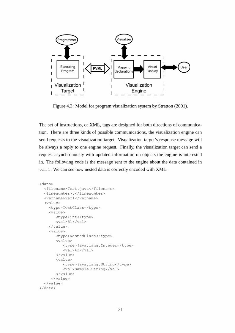
The most advanced intermediate code for visualization purposes, and debugging, is
the one proposed by Stratton (2001, 2003). He proposes a Program Visualization Meta
Language,PVML, based on XML. PVML is a central part in his ideal decoupled sys-
tem, where a machine (visualization engine) can visualize and debug a program exe-
cuting in a remote machine (visualization target). Thus, PVML allows the communica-
tion between both machines by exchanging XML documents. As shown in Figure 4.3
PVML stands in between both sides of the communication, and allows a clear identi-
fication of tasks. PVML tries to be language independent, so it not only allows free
interpretation of the generated XML document, but also any programming language
interpreter or debugger can generate documents in PVML. PVML is intended to just
cover the most used features of common procedural, declarative and logical program-
ming languages. However, if some of the features of a given programming language
are not covered by PVML, PVML can be extended with XML standard methods to
accept it and to describe the execution of a program in that language.
30
Executing
Program
Visualization
Target
Mapping
declarations
Visualization
Engine
Visual
DisplayPVML
User
VisualizerProgrammer
Figure 4.3: Model for program visualization system by Stratton (2001).
The set of instructions, or XML, tags are designed for both directions of communica-
tion. There are three kinds of possible communications, the visualization engine can
send requests to the visualization target. Visualization target’s response message will
be always a reply to one engine request. Finally, the visualization target can send a
request asynchronously with updated information on objects the engine is interested
in. The following code is the message sent to the engine about the data contained in
var1 . We can see how nested data is correctly encoded with XML.
<data><filename>Test.java</filename><linenumber>5</linenumber><varname>var1</varname><value>
<type>TestClass</type><value>
<type>int</type><val>51</val>
</value><value>
<type>NestedClass</type><value>
<type>java.lang.Integer</type><val>42</val>
</value><value>
<type>java.lang.String</type><val>Sample String</val>
</value></value>
</value></data>
31

The engine requests to the target match with common debugging tasks. Program exe-
cution control (run , compile , cont ) and managing breakpoints and watched vari-
ables (watch andbreak ) are the bulk of the instructions. Moreover, Stratton also
takes into account the stepping problem. He is aware of the different functionality of
such tools amongst the different paradigms and even different debuggers. His basic
definition of step is the execution of one line of source code. An optional parame-
ter will request the target to execute the program until the current context terminates.
He also defines a more advanced instruction/request,stepi , that will execute source
code expressions instead of lines, thus making it more appropriated for novices.
The target will respond to previous requests by sending back certain instructions. The
most important instructions arebreakresp andlocation . Both of them will indi-
cate the success of a break request or of an execution control instruction.Location
will indicate the currently executed line of the program after the control instruction.
For example, this information can be used for source code highlighting.
The third kind of communication is for those asynchronous events at the target that the
engine has asked to be informed about. There are actually two of them,dataandframe.
A data instruction will contain the information and value of variable, and it will be
transmitted only when the engine has placed a “watch” upon it, and its value has been
modified. Aframe will indicate to the engine when the current context changes.
The implementation of PVML on the target engine will take advantage of already de-
veloped debuggers and interpreters. They will be wrapped within a driver that gener-
ates the correct PVML documents and manages the communication with the engine.
Summarizing, PVML manages to define the required communication between two sep-
arated systems. It makes possible to design a visualization engine that can be used to
debug or visualize programs written in different programming languages. However,
due to inherent nature of several programming languages, the results of the request to
different engines could lead to unexpected visualizations. While Stratton defines the
minimum set of instructions expected to be accepted by all programming paradigms,
the semantics of those instructions can differ.
32

4.2.10 Jeliot 3 and MCode
Jeliot 3 introduces the MCode. MCode is the trace of a program, as a list of instruc-
tions, that details step-by-step the result of interpreting the program.
Section 5 explains MCode in great detail. In this section, we will compare MCode with
the intermediate codes proposed by Patton (1989) and by Stratton (2003).
E-code (see Section 4.2.4) and MCode produce the same result: a visualization of a
running program, step by step, by graphical means. However, their intermediate code
differs. E-code is the result of compiling a program, just like Java bytecodes, and its
execution is tightly coupled with the visualization engine (animator), which decides
what to execute next. MCode is the result of the interpretation of the program, a trace
of its execution. Jeliot 3’s visualization engine is separated from the program logic
interpretation. However, it needs to keep the information it might need for processing
the following MCode instructions.
PVML (see Section 4.2.9) and MCode share the same goal: to provide the visualiza-
tion tool with a trace of a program’s execution. PVML maps program state changes
into a well formed XML document. Its information is gathered from the JPDA (see
Section 4.2.3), so it is not as complete and detailed as the one that MCode provides,
gathered from DynamicJava. PVML was not used in Jeliot 3 for this reason, and for
its XML format. It was a problem to generate valid XML documents that could be
processed when a program contained user input method calls (Myller, 2004).
The Leonardo system (see Section 4.2.5) and Jeliot 3 are aimed at different classes of
users. However, there could be a way to produce a Jeliot-like animation in Leonardo
by defining the required Alpha graphical predicates and by setting every variable as
relevant. This solution though seems infeasible. Again, the system will only detect
when a variable has changed, but not the expression that modified it.
4.3 Classification
As Yehezkel (2002) did (see Section 2), I have decided to extend Price’s taxonomy
to adapt it to my needs: to reflect the use of intermediate codes and technical issues
concerning the implementation of the tools.
33

4.3.1 Taking into Account Price’s Taxomomy
Price’s taxonomy (Price et al., 1993) addresses a part of the problem of classifying sys-
tems from a technical point of view. He does so by hisMethodproperty. The method
property emphasizes thevisualizertask. According to Price’s words, the visualizer is
“the person who created the visualization from the original program”.
In Price’s taxonomy, the use of intermediate code is evaluated through the different
subcategories of the property. For example, the visualization style points out the dif-
ference between those tools that produce animation automatically (Dynalab, Jeliot,
Javavis) and those that require a certain graphic library to produce it (Leonardo) or
those that require the visualizer to write an specific program to visualize it (Jawaa,
ANIMAL ). Another subcategory is “how the connection between visualization and the
actual source code is made”. Price distinguishes different possibilities: some programs
like Jawaa andANIMAL are instrumented: they require the visualizer to modify the
source code to add visualization commands at certain interesting points. Others re-
quire the source code to beannotatedwith semantical information (Viz). And others
useprobes: they execute the source code trough a special compilers, interpreters or
debuggers, which retrieve the information available from the execution environment
(e..g.Jeliot, Javavis).
4.3.2 Extending Price’s Taxonomy
While Price’s taxonomy deals with the technical point of view, reviewing these systems
we have identified some other subcategories. Due to Price’s hierarchical taxonomy
design, it is possible to integrate them into it, see Figure 4.4.
The information gathered in the intermediate codes can differ in the level ofcomplete-
ness, property D.1.3. While this is closely related to the ultimate goal of each tool,
future revisions of such tools will find it easier when the smallest details have been
taken into account during its design.
The data transferred between source code and the visualization engine can carry se-
mantical information or pure graphical representation. This affects thereusabilityof
the efforts involved in generating the intermediate code or constructing the visualiza-
tion, property D.1.4. If the conveyed information is purely graphical it will be harder to
34
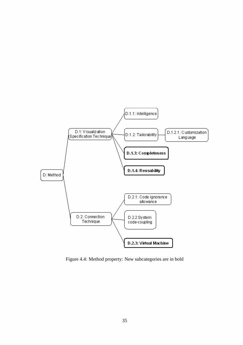
Figure 4.4: Method property: New subcategories are in bold
35

abstract it and construct a different visualization. On the other hand, if the information
is only semantical, different interpreters produce different visualizations, and we only
need to modify one side of the visualization tool.
Finally, most of the reviewed tools make use of avirtual machine, property D.2.3.
However, some of them use it to generate the visualization instructions and some others
to interpret the visualization instructions.
4.3.3 Getting All Together
Table 4.5 categorizes the reviewed systems. Each category is ranked or an attribute
is given. Ranks go fromnoneto high, going through little and medium. Attributes
depend on the category; and when the category is taken from Price’s taxonomy, they
are the same as in Price’s taxonomy.
D.1 D.1.1 D.1.2 D.1.2.1 D.1.3 D.1.4 D.2 D.2.1 D.2.2 D.2.3
System
Name Vis
ualiz
ation
Specific
ation
Sty
le
Inte
lligence
Tailo
rabili
ty
Custo
miz
ation
Language
Com
ple
teness
of
Inte
rmedia
te
Code
Reusabili
ty o
f
Genera
ted
Inte
rmedia
te
Code
Connection
Techniq
ue
Code I
gnora
nce
Allo
wance
Syste
-Code
Couplin
g
Virtu
al M
achin
e
Aho's High High
Pascal's
pcode High High both sides
Java High Medium Executing
Dynalab Automatic Little None High Medium probes visualizing
Leonardo library High
Declarative
specification
User
dependant Little
instrument/
probes
Little/Non
e High visualizing
PVML Automatic None Medium Medium probes Little both sides
Jeliot 3 Automatic Little Little High High probes Medium visualizing
Javavis Automatic Little Little Medium High probes Little compiling
Viz library None
User
dependant High
instrument/
probes Medium High visualizing
Jawaa hand-coded Normal
Interactive
manipulation/
procedural
visualizations
User
dependant Little instrument Little High visualizing
Animal
library/hand-
coded High
Interactive
manipulation/
procedural
visualizations
User
dependant Little instrument Little Medium
Figure 4.5: Table of properties and systems
The three programming language systems, Aho, Java, and Pascal-P, have an interme-
diate code that is complete or almost so. They cannot lose any information in the
compilation if they want programs to be valid. As said before, Pascal-P compiler and
its generated executables can both be interpreted in a virtual machine. Java executes
the program in its own virtual machine, JVM. Aho’s intermediate code and P-code
36

prove to be able to be openly adapted, extended or modified to accept new languages.
Java makes this more difficult.
Automatic specification occurs on Dynalab, PVML, Jeliot 3 and Javavis. The intelli-
gence associated to such systems is low. They are not able to identify algorithms or
particular high-level data types. All automatic systems’ connection technique is by
“probes”.
Tailorability is another discrete feature, only Leonardo andANIMAL deliver a high
degree. Leonardo’s Alpha language andANIMAL script provide several ways to adapt
the visualization. Jawaa’s scripting language is more limited.
The completeness of the generated intermediate code is mostly user dependent in those
systems that are highly “tailorable”. The completeness of the other systems depends
mostly in their original goals. Thus, Jeliot 3 scores high due to its completeness objec-
tive.
Systems with high tailorability are too close to the algorithm’s implementation, mak-
ing the reusability low. The architecture of other systems make it easy to reuse the
generated code by adding plug-ins or different interpreters. That principle holds true
for Jeliot 3, Viz, PVML and Javavis.
Leonardo and Viz offer a mixed connection technique: probes and instrumented code.
The user will instrument their code, with declarative primitives (Leonardo) or history
events (Viz). The execution or interpretation of the instrumented code will send infor-
mation to the visualization engine.
The only system that allows a certain level of code-ignorance is Viz. Its history events
can be placed without much knowledge of what the algorithm does. On the other hand,
scripting languages and Leonardo require a high level of knowledge of the algorithm
to instrument the code with proper calls or primitives.
The system-coupling occurs when the program to be visualized is closely attached
to the visualization tool. PVML, for example, can have two completely separated
systems, one producing the XML document and the other interpreting them. Javavis
uses a similar design. Leonardo, Viz and Jeliot 3 are “tightly coupled” with the program
code to be visualized.
As we have seen virtual machines are used in almost every tool. While most of the
37

tools use it exclusively to maintain and to produce the visualization, PVML generates
its documents through a virtual machine. Jeliot 3 generates its MCode through an
interpreter.
Most of the current visualization tools use the Java platform. In last Program Visu-
alization Workshop (Korhonen, 2004), about half of the presented tools were related
to the Java platform. Systems were designed to teach Java using the Java platform,
both to acquire the information and to present it in different ways. All this accumu-
lated expertise in designing Java visualization tools lets Java as the platform of choice
when designing a new tool. While Java is a natural option when implementing a tool to
be executed in different systems, it is important not to exclude different programming
languages of being animated with those systems.
This taxonomy has shown different approaches taken when designing a visualization
tool. Developers of new tools should use this information when designing them, avoid-
ing common mistakes and reusing the shown ideas.
38

Chapter 5
MCode explained
5.1 Definition of MCode
MCode is a general language, so that interpreters of any programming language can
generate valid MCode. It was developed with object-oriented features in mind, but any
imperative language can fully render its execution in MCode.
MCode is the intermediate language used in Jeliot 3. It communicates program inter-
pretation information to the animation engine, providing the animation engine with the
information needed to generate an animation of the running program.
MCode is a text-based language. It consists of text lines or MCode instructions, where
each is divided in several tokens. It can be saved in a file and later restored and ani-
mated.
5.2 MCode in Jeliot 3
MCode is the solution adopted in Jeliot 3 to separate the program interpretation from its
visualization. The system structure of Jeliot 3 (see Subsection 3.1.3) implies the need
for a method of communication between both sides of the animation system. Differ-
ent approaches to implement the communication were studied (Myller, 2004), such as
using the intermediate code proposed by Stratton (2003). Finally, a new intermediate
39

code was designed from scratch.
As we were designing a visualization tool for the Java language, another possibility was
to make use of the information given by the Java Virtual Machine (JVM), accessible by
means of the Java Debugging Interface (JDI). This method proved to be successful in
the development of Javavis (Oechsle and Schmitt, 2002) (see Section 4.2.6). However,
Jeliot 3 had different requirements that the JDI did not fulfill. Additional information
not provided by JDI was needed to produce the animation. The main disadvantage of
using the JDI was that we could not extract detailed information about the expression
being executed. JDI mainly informs when and how the states of the virtual machine
structures change, e.g., objects and method stacks. Obviously, to detect if a change is
due to the execution of an “if” branch or an “else” branch is out of the scope of the JDI.
Moreover, expressions (e.g. “3+1”) will not inform JDI of themselves being executed.
As the obtainable debugging information was not enough, we focused on using a Java
interpreter. The interpreter would execute step by step, traversing a syntactical tree.
This interpretation would provide a much more detailed transcript of a program’s exe-
cution. Three Java language interpreters were already available when designing Jeliot
3: Iava(Richter, 2000),BeanShell(Niemeyer, 2003) andDynamicJava(Koala Project,
2002). All of them add scripting features to Java; unfortunately, some Java features
were not fully implemented. Myller (2004) has a detailed discussion about the selec-
tion of the most suitable interpreter. Summarizing, DynamicJava was chosen because
it closely followed the Java specifications. Thus, Java students do not need to learn the
details of the new scripting additions to Java that will not work when compiling their
programs with a common Java compiler.
5.3 MCode Specification
MCode Specification is a separate document and it has been published online (Moreno
and Myller, 2004) and can be found as Appendix A. It includes the formal information
that defines a valid MCode program. Following sections will explain how to generate
and interpret a valid MCode program.
40

5.4 MCode Details
MCode resembles intermediate codes used in current compilers. We can compare
MCode to the intermediate languages proposed by Aho et al. (1986),triplesandquadru-
ples(see Section 4.2.1). It is important to mention that even though the syntax can be
similar, MCode instructions do not need to be evaluated; they are the result of an eval-
uation, while thetriples andquadruplesare a translation of the original source code,
where nothing has yet been executed or evaluated.
The format of MCode instructions is not fixed as different constructs need special in-
formation. Nevertheless, the bulk of the instruction set follow a similar pattern, and
different operands or tokens can be identified. Table 5.1 shows an example of MCode
instruction and identifies each field of it. Fields are explained later.
ASSIGNMENT 4 5 6 1 int 6,9,6,20
Statement Code Reference Related Ref. Related Ref. Value Type Location
Table 5.1: Different elements that compose an MCode Instruction
Expression/Statement code A mnemonic for every Java statement or ex-
pression is used: e.g.AEstands for Add Expression. Auxiliary MCode instruc-
tions also have a mnemonic. The chosen names are heavily related to the ones
used by DynamicJava. However, they are close to the common notation used in
procedural and object oriented languages. The meaning of this token is the same
as the operator in the quadruples. It identifies the operation and helps the in-
terpreter to process other instructions. The difference is that quadruples are self
contained, while some MCode statements require of other auxiliary statements
to be meaningful and interpretable.
Reference Every instruction (except the auxiliary ones) produced when interpret-
ing a program is identified by an unique number. This is needed because in-
structions need to be identified before being produced. A physical identification
is not possible, because we can not guess how many instructions will occur be-
tween the auxiliary instructions and the actual instruction. In the quadruples,
their references are assigned consecutively. Previous instructions will be refer-
enced to form another one, e.g. both operands of and Add Expression can refer
41

to two Literal instructions. Temporary results may be retrieved by requesting
their reference numbers.
Related References Most of the MCode sentences refer to previous MCode
instructions that build the operation up. As said before, Add Expression will re-
fer to the operand references of both sides of expression, rather than their value.
Flow-control statements will refer to a condition expression, and so on.Quadru-
plescontain as well references to the arguments of the operator.
Value Most sentences will contain the value resulting from an expression evaluation.
If it is a flow control statement, it will contain a boolean value indicating the
result of the condition. When the value of an object or array is needed, an unique
identifier for the object is returned. In the case of Java, this is thehashcodeof
the object, while in other languages, this could be the physical memory location
or any other unique identifier. The compiler’s intermediate languages do not
contain information aboutValue . Value will be obtained in run-time and it
will replace the quadruple.
Type Every expression that contains aValue must specify its type. The compiler’s
intermediate languages do not contain information aboutType . Information
about types is gathered in the first stages of the compilation, and used when gen-
erating the target machine code. The machine instructions will carry information
about the type, whether having a different instruction for each type and operation
or in a special field of the instruction. MCode currently supports the following
types: boolean, byte, short, int, long, char, float, double, string, void and refer-
ence. Reference is used for objects. An interpreter for a different language (e.g.
C) could use it to implement pointers and structures. Arrays are also supported
and they are described following the Java notation, e.g. one-dimensional integer
array will be described as “[I”, “[” denoting an array and “I” standing for an
Integer object (Lindholm and Yellin, 1999).
Location This contains the location of the expression in the original source code
file. This is a requirement for the visualization. Intermediate languages, like
quadruples, do not carry this information. However, modern languages can at-
tach location information to its compiled code to help debugging.
The following example shows how the previous information applies to a normal MCode
instruction:AE 9 7 8 4 int 9,4,9,11 . AE is the code for the Add Expression.
42

9 is the reference of this instruction, while7 and8 refer to previous instructions, most
probably two literal instructions.4 is the result of the operation of typeint . Finally,
the location of the expression is expressed.
While this organizationproves to be true for common MCode instructions, special
instructions have been defined to fully express the result of the evaluation. For exam-
ple, scopes are created explicitly. Others require a lot of information to be faithfully
represented. As an example, Array Allocation requires dimension values, dimension
expression references that are specific to Array Allocation.
Console INPUT/OUTPUT requires special treatment. First, they are normal function
calls from the point of view of the interpreter, but their visualization is far from being
straightforward. INPUT requires the user toentersome data, normally through some
window drawn by the animation engine. That data needs to be passed back to the
interpreter, as it should modify its state and following instructions. OUTPUT prints a
string in the console. However, we need to know which functions are actually doing
that. The source code interpreter should be modified to report an OUTPUT instruction
when such a method or function call is called.
5.5 Generating MCode
This section explains how MCode is produced by DynamicJava. Thus, it is specific
to the Jeliot 3’s implementation. However, it aims to guide those that would like to
generate MCode from their own interpreter or to understand the Jeliot 3 source code.
5.5.1 DynamicJava
DynamicJava is implemented by Stéphane Hillion, and is part of the Koala Project
(Koala Project, 2002). The Koala Project has been developing high quality open source
tools and libraries related to Java and XML technologies.
DynamicJava is written completely in Java and supports different methods to be started,
so it was not a problem to integrate it in Jeliot 3. Figure 5.1 represents the structure or
the execution flow of DynamicJava.
43

Interpreter
-sourcecode Parser -
tree NameVisitor
-tree Type
Checker-
treeand
classesEvaluation
Visitor-result
6?
6
?
6
?
-¾
TreeClass-Compiler
Tree ClassInfo ClassFile
Figure 5.1: Execution flow in DynamicJava (Moreno and Myller, 2004).
First of all, the source code is parsed into asyntax tree, consisting of nodes. Each node
would represent the actual construct from the source code (e.g. variable declaration,
array allocation). The tree would be complemented with the result of compiling the
source code of the classes. This way DynamicJava supports objects, as every object
is a true instance of its compiled class. Information at run-time is accessed by means
of the reflection abilities of Java. For example an object method call will execute the
bytecode corresponding to such a method. But the bytecode is modified to traverse the
tree created by DynamicJava of that method instead of the actual body of the method. It
is when executing/traversing that tree when we can obtain all the information we need
from the different node. This makes it difficult to retrieve certain information per-
taining the object creation, as the real objects are constructed outside the scope of the
DynamicJava evaluation visitor. This will be treated in more detail in Subsection 5.5.2.
5.5.2 MCode Production
MCode is produced mainly in the Evaluation Visitor, where the interpretation is carried
out. However, some information required to produce the complete MCode is found in
other DynamicJava classes. Here we will explain how and where the most relevant
information is gathered and processed.
44

Evaluation Visitor
As previously noted,EvaluationVisitor was the main class that needed to be
modified. In the next subsections, we will describe how MCode is produced for certain
subsets of Java expressions and statements:
Method Calls
The visitor methodStaticMethodCall is the entry point in Jeliot 3 to the evalu-
ation visitor. It is the method called when invoking the main method of a class from
TreeInterpreter . The visitor will generate the instructions about the method
call. The method call will be opened with anSMCinstruction detailing the name of
the method, the number of parameters and the calling object. Parameters will then be
evaluated to form the method call. Finally, DynamicJava will invoke the method with
all the information. When the invocation ends a special statement is produced to indi-
cate the end of static method call (SMCC). Similar instructions are produced for object
method calls,OMCandOMCC.
Two problems have been solved in order to make the MCode obtained from Dynamic-
Java coherent. First,StaticMethodCall andReturnStatement visitors main-
tain a stack in order to manage multiple method calls, as done in the statementreturn
object.method() . A reference number is pushed into the stack in every method
call. The return statement visitor will pick it up from the top of the stack and that will
identify the return statement.
Second, when a static method call refers to a foreign method, meaning that no source
code is provided for it (e.g. from Java API), the normal invocation will only return the
value, if it is not a void method. But we need to generate the MCode instructions to
visualize the call properly. Thus, we simulate the MCode instructions corresponding
parameter passing and method declaration. Finally, the value returned must be inside
a return MCode instruction, so it is simulated too.
It is in the Static Method Call visitor where most of the I/O calls are detected. They
are handled in such a way that Jeliot 3 can support, with minor modifications, the
visualization of different Input methods. Jeliot 3 supports standard output (e.g. Sys-
tem.out.println()) and it also supports the output method provided in Jeliot 2000, Out-
put.println().
45

Return Statement
Return statements complement method calls. A return statement can contain a value
to return or nothing at all (a void method or function). If there is something to be
returned aBEGIN statement is produced before visiting the expression to be returned.
Otherwise a simple return statement is produced with the special constantCode.-
NO_REFERENCE, so Jeliot 3 interpreter will not look for an expression.
Simple Assign Expression
Assignments are divided into two steps. First, the right-hand side of the expression
is evaluated and then the identifier is evaluated and resolved. ABEGIN statement is
produced to mark the beginning of a new assignment. After the right hand side has
been evaluated a special statementTO is produced. It marks the beginning of the left-
hand side expression, where the value obtained interpreting the right expression will
be stored. This left expression was not evaluated in the original DynamicJava, as it is
not needed to modify the context. However, we need to visualize that expression, so an
“artificial” visit was added to retrieve the information about it. Anevaluating flag
is set to show that it is an “artificial” visit. Finally, we produce the assign instruction
with references to the both sides of the expression.
Qualified Name
Qualified Names are the names already declared (e.g. variable names and any other
identifier) and they are used in expressions. Its visitor was modified to take into ac-
count theevaluating flag. The reason for having two different behaviors is that
DynamicJava throws anExecutionError when visiting an uninitialized qualified
name. That occurs when an assignment method (asSimpleAssignExpression )
visits its left hand side for visualization purposes before it has a value. When the
evaluating flag is false, DynamicJava invokes thedisplay method to avoid un-
necessary exceptions. However, both methods (visit anddisplay ) produce the
same MCode.
Variable Declaration
Generating the MCode for variable declarations is straightforward, as DynamicJava
provides all the needed information. Those variables that have an initialization expres-
sions are treated normally. Only if an initialization expression for the variable is found,
46

we have to modify the normal process to visualize the initialization. This is done by
simulating an simple assign expression after the variable is declared. This will make
easier to develop a visualizer, but it also means a semantic loss. And while it is not
important for visualization, it can be meaningful for further processing of the MCode
from other tools.
Flow Control Statements
All flow control statements work similarly. Here, we will explain how awhile state-
ment produces its MCode.
First of all, theWhileStatement visitor keeps the reference to the condition that
will be visited and will determine whether to enter the body of the statement. If the
condition holds the visitor produces aWHILEstatement withTRUEas a value. Then
the body is evaluated, producing its own MCode.
Break or continue visitors throw exceptions to be caught by the flow control state-
ments. When they are caught their corresponding MCode statement is produced. This
statement reflects where the break or continue has happened (WHILE, FOR, DOand
SWITCHexpression).
Boolean and Bitwise Unary Expressions
This group contains the not (! ) and complement (˜ )operators. There are two differ-
ent possibilities. On the one hand the expression can be constant and no evaluation is
performed by DynamicJava, so the generation of MCode is straightforward. However,
as there is no expression to be referred, there is no node containing that constant, only
a value is returned.Code.NO_REFERENCEis used to indicate this fact to the inter-
preter. On the other hand, when there is an expression to negate, aBEGINstatement is
produced before the expression to be negated is visited. Finally the unary statement is
produced returning the value and referring to the expression it affects.
Unary arithmetic expressions
This group contains increments and decrements (++, -- ). No special modifications
were carried out in these visitors. They just generate aBEGINstatement and their own
statement (PIE , PDE, PRIE, PRDE), that returns the modified value and the type.
Binary Expressions
47

This group comprises all boolean, bitwise and arithmetic binary operators. As usual,
a BEGIN statement is produced, anticipating what the operator will be. Then both
sides of the expression are visited and their values are collected. Before each of these
two visits, there is one special MCode statement: aLEFT statement, for the left side,
and aRIGHT statement for the right side. Finally the binary statement is generated
referring both sides and the value resulting of applying the operator to both sides of the
expression.
Compound Assignment Expressions
This group contains all bitwise and arithmetic compound assignments. Compound
operators are for example+=, -= , * = and/= . The visitors of these compound assign-
ments have been modified to produce MCode that decomposes the compound assign-
ment into a simple assignment and a binary operation. For examplea+=3-b will be
interpreted asa=a+(-b) .
Then, the code of the visitors is just a composition of an assignment and a binary
expression as its right hand side. This binary expression has as its sides the same ones
as the compound assignment. As a result, two fake or artificial visits are done to the
left-hand side of the compound assignment.
Again, as in the variable declaration case, some information is lost. The result of
decomposing the compound assignment makes the visualization for novices easier, but
the real expression is lost.
Array Allocation and Access
Arrays are treated different than classes, as their interpretation and visualization re-
quirements differ from the classes ones. Arrays in Java are very flexible in their content
and structure, thus the information gathered and passed to a visualization engine must
be rich to be able express them.
As said before, array allocation requires a big amount of information in order to show
the complete process of allocation. First, the expressions to calculate the dimension
values are evaluated. The references to the expression and the actual dimension value
are kept. Once the array is created by the interpreter we can produce the array alloca-
tion instruction (AA) with its hashcode that will identify it.
If the array declaration contains an initialization expression, then another visitor will
48

be calledArrayInitializer that will create the array with the values provided.
This time we have preferred to create a new instruction to indicate the initialization
AIE , rather than simulate multiple assignments, to allow a differentiated, and faster,
visualization of the array initialization.
Class Allocation
Class allocation MCodegeneration is dealt with in Section 5.5.2.
Field accesses
Two field accesses are supported by the MCode, object field access and static field
access. The main difference is that we need to obtain the information about the object
or the referring class depending on the access. In the first case we need to resolve the
object before we can refer to it.
Tree Interpreter
This class contains methods to interpret the constructs of the language. This class is
the one called from Jeliot 3 to start interpreting a program or a single method. There
are two main methods that have been modified.
interpret(Reader r, String fname)
This method receives the source code and invokes the three visitors of DynamicJava:
NameVisitor , TypeCheker andEvaluationVisitor . This method catches
the execution and parsing error exceptions and generates MCode to notify Jeliot of
the possible lexical, syntactical or semantical errors that are found during the inter-
pretation. The instruction Interpretation errors generate an exception that is caught by
this method. The instruction,ERROR, contains both the explanation provided by the
interpreter and the estimated location of the error.
interpretMethod(Class c, MethodDescriptor md, Object obj, Object[] params)
Whenever the source code of a method is available to the interpreter, and it is invoked
by the interpreter,interpretMethod will construct everything needed to interpret
it. The MCode generated by this method provides the names of the formal parameters
so they are added to the method frame as the variable names by the Jeliot 3 interpreter.
49

It also indicates the location of the method declaration in the source code by means of
a special MCode instruction:MD, method declaration. This information is artificially
generated inStaticMethodCall if the method is a foreign one. The flaginside
is set to indicate that the currently interpreted method parsed tree is available and, thus
it can be interpreted. For library methods or any precompiled classs, we need to fake
the MCode instructions to simulate its method declaration and return information.
Constructor calls are also methods and information about their interpretation is found
here as well. However, its visualization requires special MCode instructions. Unfor-
tunately, DynamicJava’s interpretation of constructor invocation and inheritance is not
the best for visualization purposes.
The behavior of DynamicJava when allocating a new object is to call the construc-
tor outside the normal interpretation of the evaluation visitor. It is called by reflec-
tion, the bytecode of the class is loaded and its constructor is invoked. The class
will contain a modified version of the original constructor. This modified construc-
tor starts by asking the TreeInterpreter to interpret the original arguments of the con-
structor callTreeInterpreter.interpretArguments . Later, it calls its su-
per methodsuper() . If the original super method call had some arguments they
are interpreted and passed in the super method call. Finally, it interprets the body
of the constructor (TreeInterpreter.interpretMethod ). This particular be-
havior causes certain problems. First, when producing the MCode for the method call,
done ininterpretMethod , the information about parameters cannot be obtained
there because it has been interpreted before ininterpretArguments . Thus, a data
structure is kept to hold the parameters information to be used later. Second, the actual
super method call interfers with the visualization order, as it will produce the MCode
related to its invocation and interpretation before the MCode of the first constructor. As
a result, the obtained MCode produces a wrong animation, where the super methods
are animated before their calling constructor. Future revisions of Jeliot 3 will correct
this incorrect behavior.
5.6 Interpreting MCode
Jeliot 3’s architecture and implementation allow different kind of interpreters to pro-
duce their own visualizations. Jeliot 3 provides an interface to handle MCode instruc-
50

tions, so visualizers do not need to implement a parser for it. They just need to ex-
tendMCodeInterpreter class and implement the abstract methods that handle the
MCode instructions. Finally, they need to register themselves as a secondary inter-
preter, because the primary interpreter is Jeliot 3’s standard animation engine. This
way Jeliot 3 GUI will recognize the new interpreter and add a new tab to the visualiza-
tion windows list. Users can click in the tab to view the visualization generated by the
new interpreter.
Currently, Jeliot 3 distribution comes with one secondary interpreter. It visualizes the
call tree. Every method call is shown and displayed as nodes tree graph. Creating this
new simple visualization was straightforward and a proof of concept of the viability of
the design.
5.7 MCode Examples
This section contains two examples. Both examples shows the Java source code, the
valid MCode generated, and explanations of the different instructions.
5.7.1 Procedural Program
This is a simple procedural program that just copies the String"Word" to all cells of
an array.
1 import jeliot.io. * ;2
3 public class ProcExample {4
5 public static void main(String[] args) {6 int size = 1;7 String[] wordsArray;8 wordsArray = new String[size];9
10 int i = 0;11
12 while ( i < size){13 wordsArray[i] = "Word";14 i++;15 }16 }
51

17 }18
In this example we can see how the MCode initializes the MCode interpreter with the
main information about the classes, their fields, methods and constructor. Following
some snippets of the produced will be shown and explained with more detail. More
concretely they will show:main methodcall, avariable declaration, anarray alloca-
tion, a while loop, and anarray access. MCode mnemonics have been replaced with
more descriptive names.
• Initialization
CLASS§ProcExample§java.lang.Object
METHOD§main§void§8§[Ljava.lang.String;
CONSTRUCTOR§
ENDCLASS§ProcExample
These instructions correspond to the initialization of the MCode interpreter. It details
the name of the different classes contained and its correspondent super classes. For
each class, its methods, constructors (no one this time, default constructor is displayed),
and fields.
• ProcExample.main(new String[0])
STATICMETHODCALL§main§ProcExample§1§1,1,1,31
BEGIN§PARAMETER§2§1,1,1,31
LITERAL§3§0§int§1,29,1,29
ARRAYALLOCATION§2§114fc36§java.lang.String§1§3§0§1,18,1,30
PARAMETER§2§114fc36§[Ljava.lang.String;
PARAMETERNAMESLIST§args
MD§4,5,18,5
Then the main method call, that starts the program generates its MCode. This call
is generated by Jeliot 3, and can be modified. By default and in this case, it is the
52

main method (ProcExample.main(new String[0]) ). Static method call in-
struction requires the name of the method and its class. Method calls, both static
and non-static, follow the same way. Parameters are evaluated. For each parameter
a PARAMETERinstruction is generated, its beginning is marked by aBEGIN instruc-
tion. This time we have an array allocation,new String[0] , this will be dealt
later. When all parameter have been dealt with, a list comprising the names of all of
them is generated,PARAMETERNAMESLIST. And finally theMDinstruction gives the
location of the source code of the whole method, useful for highlighting it.
• int size = 1;
VARIABLEDECLARATION§size§0§?§int§NOTFINAL§6,9,6,20
BEGIN§ASSIGNMENT§4§6,9,6,20
LITERAL§5§1§int§6,20,6,20
TO§6
QUALIFIEDNAME§6§size§?§int6,9,6,20
ASSIGNMENT§4§5§6§1§int§6,9,6,20
Next in the code, we have a simple variable declaration with an initialization expres-
sion. The variable declaration simple returns the name, the value (unknown), and
whether if it is final. The initialization is a simple assignment. Assignments are also
started with aBEGIN instruction. TheBEGIN instruction shows what is beginning
and its reference, “ASSIGNMENT” and “4”.ASSIGNMENTinstruction identifies it-
self with the reference “4”, and refer to both sides of the expression, “5” and “6”.
• new String[size];
QUALIFIEDNAME§12§size§1§int§0,0,0,0
ARRAYALLOCATION§11§ba5a81§java.lang.String§1§12§1
§8,31,8,46
This array allocation first evaluates the dimension expressions, only one with refer-
ence number “12”. TheARRAYALLOCATIONinstruction contains the reference that
identifies the instruction and the hash code that identifies the array itself. The rest of
parameters are filled, “1” dimension, defined by the instruction “12” of size “1”.
53

• while ( i < size)
BEGIN§§LESSTHANEXPRESSION§12,17,12,24
LEFT§18
QUALIFIEDNAME§18§i§0§int§0,0,0,0
RIGHT§19
QUALIFIEDNAME§19§size§1§int§0,0,0,0
LESSTHANEXPRESSION§17§18§19§true§boolean§12,17,12,24
WHILE§17§true§0§12,27,15,9
These instructions correspond to the first iteration of the while loop in the example.
In the MCode section of a while loop, the condition is evaluated first. This time we
have a less-than expression. Both sides are evaluated, and the expression instruction
is composed of the reference to itself ("17"), and to both sides of expression (“17”
and “18”). The result of the expression is returned as well, the value is “true” of
type “boolean”). Finally, theWHILEexpression refers to the condition and repeats the
result, indicating whether its body is going to be evaluated or not.
• wordsArray[i]
BEGIN§ARRAYACCESS§24§13,13,13,25
QUALIFIEDNAME§25§wordsArray§ba5a81
§[Ljava.lang.String;§0,0,0,0
QUALIFIEDNAME§26§i§0§int§0,0,0,0
ARRAYACCESS§24§25§1§26§0§?§java.lang.String§13,13,13,25
An array access will visit both the variable that contains the array, "25", and the ex-
pression that refers to the accessed cell, "26". With theARRAYACCESSinstruction
the MCode interpreter has all the needed information to identify the right cell and to
visualize its access.
5.7.2 Object-oriented Program
This is a more complicated example involving object-oriented concepts. This example
allocates a Square object. Rectangle is the super class of Square, and contains some
54

fields and methods.
1 import jeliot.io. * ;2
3 public class Rectangle {4 int width,heigth;5 Rectangle(){6 width=0;7 heigth=0;8 }9 Rectangle( int w, int h){
10 width=w;11 heigth=h;12 }13 public int getArea(){14 return width * heigth;15 }16 }17
18 public class Square extends Rectangle{19 int side;20 Square(){21 side=0;22 }23 Square( int s){24 super (s,s);25 side=s;26 }27 }28 public class MyClass {29 public static void main() {30 Square square = new Square(3);31 int area = square.getArea();;32 }33 }34
In this example we will pay attention to theinitialization of the MCode interpreter, a
class allocation, asuper method call, and areturn statement
• Initialization
CLASS§Rectangle§java.lang.Object
FIELD§width§int§0§?§4,5,4,13
FIELD§heigth§int§0§?§4,5,4,20
METHOD§getArea§int§1§
CONSTRUCTOR§
55

CONSTRUCTOR§int,int
ENDCLASS§Rectangle
These are the initialization instructions of the rectangle class, the different constructors
information can be better appreciated than in the previous example. As well,FIELD
information is displayed. All this information will be of great help when allocating new
objects, as the MCode interpreter needs to know in advance the fields of the object, so
it can initialize them properly.
• new Square(3)
CLASSALLOCATION§3§Square§Square§1§30,25,30,37
BEGIN§PARAMETER§4§30,25,30,37
LITERAL§4§3§int§30,36,30,36
PARAMETER§4§3§int
CONSCN§3
--BODY OF CLASS ALLOCATION
CLASSALLOCATIONCLOSE§3§18b7298§30,25,30,37
Allocating a class differs from an array allocation in that we need to pass the infor-
mation about the constructor call, as we will do in any other method call. This time
we have an special instruction,CONSCNor Constructor Call Number. This instruction
is placed to overcome the problems of DynamicJava. When the call allocation ends
(CLASSALLOCATIONCLOSE) it returns the hash code that identifies the class in a
similar way than array allocation does.
• super(s,s)
QUALIFIEDNAME§7§this§18b7298§Square§0,0,0,0
OMC§super§2§7§this§0,0,0,0
BEGIN§PARAMETER§5§0,0,0,0
QUALIFIEDNAME§5§s§3§int§0,0,0,0
PARAMETER§5§3§java.lang.Integer
BEGIN§PARAMETER§6§0,0,0,0
56

QUALIFIEDNAME§6§s§3§int§0,0,0,0
PARAMETER§6§3§java.lang.Integer
PARAMETERSNAMELIST§w,h
MD§0,0,0,0
-BODY OF RECTANGLE(S,S)
OMCC
This method call corresponds to a super method call (this.super), and it is embedded
in the body of the class allocation. It is just like a normal object method call. In the
MCode instructions all location information is null (0,0,0,0). This is due to the fact
that DynamicJava processes the super and this methods outside the interpreter.
• return width * height;
BEGIN§§RETURN§14,9,14,28
BEGIN§MULTIPLICATION§27§14,16,14,27
LEFT§28
QUALIFIEDNAME§29§this§18b7298§Rectangle§0,0,0,0
FIELDACCESS§28§29§width§3§int§0,0,0,0
RIGHT§30
QUALIFIEDNAME§31§this§18b7298§Rectangle§0,0,0,0
FIELDACCESS§30§31§height§3§int§0,0,0,0
MULTIPLICATION§27§28§30§9§int§14,16,14,27
RETURN§25§27§9§int§14,9,14,28
This is the return expression from the method call get area. First, the MCode indicates
that we are in a return expression, that consists of a multiplication. Both sides of the
multiplication are object field accesses. As with object method calls, it first resolves
the object,QUALIFIEDNAMEand then the special instruction,FIELDACCESSrefers
to it and returns the value, "3" in both sides. Finally, the multiplication is evaluated and
it is referred by theRETURNexpression.
57

Chapter 6
Discussion and Conclusion
6.1 On MCode
MCode is another tool for developers. Its very detailed instruction set is a good starting
point to create new program visualizations. Moreover, as an MCode trace represents
what programming language construct the user is currently viewing, future tools can
make use of this information and interact with the user. For example, automatic “Stop
and Think” questions could be inferred on-the-fly, as an MCode interpreter processes
the MCode instructions.
There is, as well, the possibility to store MCode traces of chosen examples. These
traces can also be preprocessed in order to create material that accompanies the exam-
ple. For example, it could retrieve explanations of the different concepts used, or new
examples that are relate to the contents of that one.
6.2 On Taxonomy
We have extended Price’s taxonomy to include categories related to intermediate codes
in Software Visualization and updated its Method property to reflect the new categories
and how the reviewed systems fit in the new Method property.
We have observed that current intermediate codes provide a trade-off between tai-
58
lorability and reusability. Reusable codes do not let the visualizer to make extensions
or modifications that affects the visualization to it in a simple way, this is partly due to
their automatic generation. As Price et al. (1993) noted intelligence in automatic sys-
tem was low, and we have seen it is. Automatic systems only show certain intelligence
when they have to create the graphical display. They make no attempt to try to guess
what kind of algorithm it is, or what data structure they are using. Since all of them are
Java-oriented tools, every data structure except for arrays is displayed as an object.
On the other hand, the meta-study carried out by Hundhausen et al. (2002) criticizes
current taxonomies because they “encourage system roulette”. Some systems, he
claims, try just to cover some properties not yet implemented by other system. Then,
because of the focus of current taxonomies, systems are implemented based on increas-
ing expressiveness, instead of focusing in actualeffectiveness. He expects a higher
usage after effectiveness problems have been solved. Thus, Hundhausen et al. (2002)
proposes deeper studies in effectiveness, and finally designing new systems based on
the findings of such studies. The study of Ben-Bassat Levy et al. (2003) have been our
guide while working on Jeliot 3 and designing its new capabilities. Ben-Bassat Levy
et al. (2003) found that the main benefit of Jeliot 2000 is that its animation provides
a concretemodel of execution that helps in understanding programming. We have
retained such a concrete model, and provided a framework where new visualization
paradigms can be built. Thus, comparative effective studies can be carried out with
Jeliot 3 and future extensions to it.
6.3 FutureWork
Now that MCode has reached maturity, we are ready to integrate different interpreta-
tions of it into Jeliot 3. Jeliot 3 and its documentation is open source under the General
Public License, so Software Visualization developers are free to modify and use the
source code of Jeliot 3 in their own developments. However, we are open to integrate
and provide support for extensions made by other researchers. This will make Jeliot 3 a
more complete tool, where students can refer to different materials and visualizations.
Another idea is to integrate Jeliot 3 into an adaptive learning environment. Myller et al.
(2004) examined the effectiveness of Jeliot 3 with second year programming students.
That experiment revealed that novices’ requirements change at a fast pace and that a
59

basic tool, like Jeliot 3, proved to be ineffective because it could not adapt to students’
individualized learning needs. The adaptive environment would guide students through
their first steps in programming. The material would consist of lessons, corresponding
exercises, and interactive animations of the examples. The environment would be self-
adapting in order to cope with students’ progress. Processing of MCode and user
interaction would be fundamental to obtain student’s knowledge.
Integrating Jeliot 3 into BlueJ has been an anticipated goal, and now Jeliot 3 is also
available as an extension to BlueJ. Creation of objects at BlueJ can be automatically
animated at Jeliot 3. Thus, Jeliot 3 benefits from the advanced visual editor of classes
that BlueJ incorporates, and BlueJ offers a more complete system with the possibility
of animating the projects. Some glitches in the interaction have to be solved before
the BlueJ philosophy of no main method (Kölling and Rosenberg, 2001) can be prop-
erly visualized in Jeliot 3. Another advantage is that this extension will increase the
awareness of Jeliot 3 amongst the Java teaching community.
The integration of Jeliot 3 and a modern IDE is also sought after. Students would ben-
efit of the advanced features of the environment, e.g. debugger, and also an animation
of their code. Eclipse (Eclipse Foundation, 2004) is an IDE that could be used together
with Jeliot 3. Different research projects have used Eclipse. For example the GILD
project (Storey et al., 2003) has modified the interface of Eclipse to adapt it to novice
students who may find themselves overwhelmed by Eclipse’s user interface. Previous
visualization tools have already been integrated in Eclipse (Lintern et al., 2003). A
combination of GILD and a Jeliot 3 plug-in would create a helpful tool for novices.
Animation would be integrated in an modified professional environment. Then, the
shift from novice to expert programmer would be easier to accomplish.
60

Bibliography
Aho, A. V., Sethi, R., Ullman, J. D., 1986. Compilers: Principles Techniques and Tools.
Addison-Wesley.
Allen, E., Cartwright, R., Stoler, B., 2002. DrJava: a lightweight pedagogic environ-
ment for Java. In: Proceedings of the 33rd SIGCSE Technical Symposium on Com-
puter Science Education. ACM Press, pp. 137–141.
Ammann, U., 1974. The method of structured programming applied to the develop-
ment of a compiler. In: ACM International Computing Symposium 1973. North
Holland, pp. 93–99.
Association for Computing Machinery, 2004. Java Engagement for Teacher Train-
ing. http://www.gsu.edu/~matknk/java/reg97.htm (Accessed 2005-
01-02).
Ben-Bassat Levy, R., Ben-Ari, M., Uronen, P. A., 2003. The Jeliot 2000 program
animation system. Computers & Education 40 (1), 1–15.
Booch, G., Rumbaugh, J., Jacobson, I., 1998. The Unified Modeling Language User
Guide. Addison-Wesley.
Borland Software Corporation, 2004. Borland’s TogetherSoft web page.
Http://www.borland.com/together/ (Accessed 2005-01-02).
Brown, M. H., 1988a. Exploring Algorithms Using Balsa-II. Computer 21 (5), 14–36.
Brown, M. H., 1988b. Perspectives on algorithm animation. In: Proceedings of the
SIGCHI conference on Human factors in computing systems. ACM Press, pp. 33–
38.
61

Crescenzi, P., Demetrescu, C., Finocchi, I., Petreschi, R., 2000. Reversible Execution
and Visualization of Programs with LEONARDO. Journal of Visual Languages and
Computing, 125–150.
Demetrescu, C., 2004a. Leonardo computing environment.http://www.
leonardo-vm.org/ (Accessed 2005-01-02).
Demetrescu, C., 2004b. Leonardo user manual.http://www.dis.uniroma1.
it/\~demetres/Leonardo/Manual/ (Accessed 2005-01-02).
Demetrescu, C., Finocchi, I., 2004. A Portable Virtual Machine for Program Debug-
ging and Directing. In: Proceedings of the 2004 ACM symposium on Applied com-
puting. ACM Press, pp. 1524–1530.
Domingue, J., Price, B. A., Eisenstadt, M., 1992. A framework for describing and
implementing software visualization systems. In: Proceedings of Graphics Interface
’92. pp. 53–60.
Eclipse Foundation, 2004. Eclipse project web page. Http://eclipse.org (Accessed
2005-01-02).
Gray, K. E., Flatt, M., 2003. ProfessorJ: a gradual introduction to Java through lan-
guage levels. In: Companion of the 18th Annual ACM SIGPLAN Conference on
Object-oriented Programming, Systems, Languages, and Applications. ACM Press,
pp. 170–177.
Haajanen, J., Pesonius, M., Sutinen, E., Tarhio, J., Teräsvirta, T., Vanninen, P., 1997.
Animation of User Algorithms on the Web. pp. 360–367.
Hundhausen, C. D., Douglas, S. A., Stasko, J. T., 2002. A Meta-Study of Algorithm
Visualization Effectiveness. Journal of Visual Languages and Computing 13 (3),
259–290.
II, J. H. C., Hendrix, T., Barowski, L. A., 2002. Using the debugger as an integral
part of teaching cs1. In: Proceedings of Frontiers in Education. Vol. 2. pp. F1G–1–
F1G–6,http://fie.engrng.pitt.edu/fie2002/papers/1574.pdf
(Accessed 2005-01-02).
Jensen, K., Wirth, N., 1974. PASCAL: user manual and report. Vol. 18. Springer-
Verlag, New York, NY, USA.
62

Karavirta, V., Korhonen, A., Malmi, L., Stalnacke, K., 2004. MatrixPro - A Tool for
Demonstrating Data Structures and Algorithms On-the-fly. In: Proceedings of the
Third Program Visualization Workshop. pp. 26–33.
Kim, H.-C., Philipps, S., 2004. Project Vivaldi web page. Http://www.ainformatik.fh-
trier.de/ oechsle/vivaldi/vivaldi/index.html (Accessed 2005-01-02).
Koala Project, 2002. DynamicJava. WWW-page,http://koala.ilog.fr/
djava/ (Accessed 2005-01-02).
Kölling, M., Rosenberg, J., 2001. Guidelines for teaching object orientation with Java.
In: Proceedings of the 6th Annual Conference on Innovation and Technology in
Computer Science Education, ITICSE. ACM Press, pp. 33–36.
Korhonen, A. (Ed.), 2004. Proceedings of the 3rd Program Visualization Workshop.
University of Warwick.
Lahtinen, S.-P., Sutinen, E., Tarhio, J., 1998. Automated Animation of Algorithms with
Eliot. Journal of Visual Languages and Computing 9 (3), 337–349.
Lattu, M., Tarhio, J., Meisalo, V., April 2000. How a visualization tool can be used
- evaluating a tool in a research & development project. In: 12th Workshop of
the Psychology of Programming Interest Group. PPIG, Cozenza Italia, p. 1932,
www.ppig.org (Accessed 2005-01-02).
Lindholm, T., Yellin, F., 1999. The Java Virtual Machine Specification. Addison-
Wesley.
Lintern, R., Michaud, J., Storey, M.-A., Wu, X., 2003. Plugging-in visualization: ex-
periences integrating a visualization tool with Eclipse. In: Proceedings of the 2003
ACM symposium on Software Visualization. ACM Press, pp. 47–56.
Mackinlay, J., 1986. Automating the Design of Graphical Presentations of Relational
Information. ACM Transactions on Graphics 5 (2), 110–141.
Mehner, K., 2002. JaVis: A UML-Based Visualization and Debugging Environment
for Concurrent Java Programs. In: Revised Lectures on Software Visualization, In-
ternational Seminar. Springer-Verlag, pp. 163–175.
63

Moreno, A., 2004. The Design and Implementation of Intermediate Codes for Software
Visualization. Master’s thesis, University of Joensuu, Department of Computer SCi-
ence.
Moreno, A., Myller, N., 2003. Jeliot Program Animation System – Internal Documen-
tation.
Moreno, A., Myller, N., 2004. Intermediate Code Specification.
URL http://cs.joensuu.fi/jeliot/documentation.
php({A}ccessed\WWWdate{})
Myers, B. A., 1986. Visual programming, programming by example, and program
visualization: a taxonomy. In: Proceedings of the SIGCHI conference on Human
factors in computing systems. ACM Press, pp. 59–66.
Myers, B. A., 1990. Taxonomies of Visual Programming and Program Visualization.
Journal of Visual Languages and Computing 1 (1), 97–123.
Myller, N., 2004. The Fundamental Design Issues of Jeliot 3. Master’s thesis, Univer-
sity of Joensuu, Department of Computer Science.
Myller, N., Kannusmaki, O., Moreno, A., Sutinen, E., 2004. What a Novice Want:
Students Using Program visualization in Distance Programming Course. In: Pro-
ceedings of the Third Program Visualization Workshop. Warwick University, pp.
126–132.
Nelson, P. A., 1979. A comparison of pascal intermediate languages. In: Proceedings
of the 1979 SIGPLAN symposium on Compiler construction. ACM Press, pp. 208–
213.
Niemeyer, P., 2003. BeanShell. WWW-page,http://www.beanshell.org/
(Accessed 2005-01-02).
Nori, K. V., Ammann, U., Jensen, K., Nageli, H. H., Jacobi, C., 1981. Pascal-P Imple-
mentation Notes. John Wiley & Sons, pp. 83–123.
Oechsle, R., Schmitt, T., 2002. JAVAVIS: Automatic Program Visualization with Ob-
ject and Sequence Diagrams Using the Java Debug Interface (JDI). In: Diehl, S.
(Ed.), Software Visualization. Vol. 2269 of Lecture Notes in Computer Science.
Springer-Verlag, pp. 176–190.
64

Patton, S. D., 1989. The E-Machine: Supporting the Teaching of Program Execution
Dynamics. Master’s thesis, Montana State University, Department of Computer Sci-
ence.
Pierson, W. C., Rodger, S. H., 1998. Web-based animation of data structures using
JAWAA. SIGCSE Bulletin 30 (1), 267–271.
Pratt, C. M., 1994. An X-windows Program Animator for DYNALAB. Master’s thesis,
Montana State University, Department of Computer Science.
Price, B. A., Baecker, R. M., Small, I. S., 1993. A principled Taxonomy of Software
Visualization. Journal of Visual Languages and Computing 4 (1), 211–266.
Richter, M. W., 2000. The Iava Homepage. WWW-page,http://members.
tripod.com/mathias/IavaHomepage.html (Accessed 2005-01-02).
Roman, G.-C., Cox, K. C., 1993. A Taxonomy of Program Visualization Systems.
IEEE Computer 26 (12), 11–24.
Ross, R., 2004a. Dynalab.http://cs.montana.edu/dynalab (Accessed
2005-01-02).
Ross, R., 2004b. Webworks.http://cs.montana.edu/webworks (Accessed
2005-01-02).
Rößling, G., Gliesche, F., Jajeh, T., Widjaja, T., 2004. Enhanced Expressiveness in
Scripting Using AnimalScript V2. In: Proceedings of the 3rd Program Visualization
Workshop. University of Warwick, pp. 10–17.
Rößling, G., Schüer, M., Freisleben, B., 2000. The ANIMAL algorithm animation tool.
SIGCSE Bulletin 32 (3), 37–40.
Stasko, J. T., Patterson, C., 1992. Understanding and Characterizing Software Visual-
ization Systems. In: Proceedings of the 1992 IEEE Workshop on Visual Languages.
Seattle, WA, pp. 3–10.
Storey, M.-A., Damina, D., Myers, D., German, D., Hargreaves, E., Mindel, M.,
Michaud, J., 2003. Improving the Usability of Eclipse for Novice Programmers.
In: Proceedings of the Eclipse Technology eXchange (eTX) Workshop at OOPSLA.
ACM Press, pp. 35–39.
65

Stratton, D., 2001. A Program Visualisation Meta-Language Proposal. In: Lee, C.
(Ed.), Proceedings of the 9th International Conference on Computers in Education
ICCE/SchoolNet2001. Soeul, South Korea, pp. 601–609.
Stratton, D., 2003. Program Visualization Meta Language. Ph.D. thesis, School of In-
formation Technology & Mathematical Sciences, University of Ballarat.
Yehezkel, C., 2002. A taxonomy of computer architecture visualizations. In: Proceed-
ings of the 7th Annual Conference on Innovation and Technology in Computer Sci-
ence Education, ITICSE. ACM Press, pp. 101–105.
66

Appendix A
Intermediate Code Specification
Introduction
This document contains the specification for the MCode, intermediate language code
used in Jeliot 3 program visualization system.
Purpose
This document main intention is to lay a solid ground for MCode, so future modifica-
tions, additions and queries to it will have a clear reference within this document.
Scope
This document is part of the documentation of Jeliot 3. MCode was developed in order
to provide the execution information to an interpreter, which manages the visualization
scene. The interpreted language is Java and the interpretation is done by DynamicJava.
DynamicJava is a Java interpreter written in Java. Java and DynamicJava imposes some
properties to the MCode. Furthermore, the original target users (programming novices)
and their programs, also delimits the Java features that are currently supported by the
MCode, such features as threads and reflection utilities are not supported. More on this
will be explained in the following chapter.
1

References
Interested readers should point to the master theses written by Niko Myller and An-
drés Moreno, both can be found at Jeliot 3’s webpage:http://cs.joensuu.fi/
jeliot/ . Niko’s thesis (Myller, 2004) describes Jeliot 3 system and its implemen-
tation. Andrés’ thesis (Moreno, 2004) explains further the decisions that shaped this
intermediate code and compares it with different solutions, describing a taxonomy.
Overview
This language will be used to transfer evaluation information between Dynamic Java
and Director class of Jeliot 3. The information flows to one direction, from Dynamic
Java to Director (with a possible exception of the Input statements). Section A will
provide a background, introducing Jeliot 3 system and some features of MCode.
2

Overall Description
Jeliot 3 System Structure
m-codeInterpreter
DynamicJava
LauncherDirectorJeliot pipe
act7:
read6:
next8:
interprete2:
Terminate thread12:
execute4:
endingexecute
11:
start1:
direct3:
write5:
write( end )9: read10:
MCode functions
MCode is the intermediate language used to communicate the visualization engine
and the Java interpreter (DynamicJava). It mainly flows from DynamicJavato the Di-
rector. The information that carries along within is not only the information about
modified variables and modified method stacks, but also the operations that produce
such changes. and the results of those operations. This is the biggest difference from
normal compiler intermediate codes; they only indicate what operations to perform to
the assembler. In our case all operations are performed and the every result is sent to
the Director.
3

User Characteristics
This document is addressed to the following people:
Developer of Visualization SystemsThis document may provide ideas and solutions
to developers of new visualization systems, as well as provides of an existing
solution that can be merged into their ongoing projects.
Maintainer of Jeliot 3 Future developers and maintainers of Jeliot 3 should refer to
this document when modifying its source code, specially those files referring to
DynamicJava and Jeliot 3’s interpreter. They should incorporate here all changes
done to MCode to provide a state of the art document as well.
Features and Constraints
While trying to produce the more generic intermediate code some features and con-
straints where placed due to several reasons. The most important ones are the following
ones:
Java Being Java the language of choice, MCode supports most of its characteristics
and abilities. It is object oriented, so things as method calls, objects and, to some
extend, inheritance are supported.
DynamicJava Because of using DynamicJava as an interpreter from which to extract
the execution information, some of the specified ordered sequences of instruc-
tions may be too constrained to the particularity of DynamicJava. However that
is not the case for the most of instructions explained here.
Targeted audienceMCode was designed to support the development of MCode, thus
it was important to address their specific problems: MCode has a great detail
in the evaluation of expressions and the normal flow of program, so novices will
grasp the programming fundamental issues. Meanwhile, more advanced features
are not within the scope of the MCode and have not been implemented. Those
features include threads, reflection utilities and exception handling.
4

Dependencies
Right now MCode is only produced through the modified version of DynamicJava in-
cluded in the distribution of Jeliot 3. However it is up to anyone to create a new high-
level interpreter to produce its own MCode to be run by Jeliot 3’s MCode interpreter or
by one they develop. There is also the possibility to store the MCode a single text file
and be retrieved later by a MCode interpreter to produce visualization orders. How-
ever, this configuration would not allow INPUT/OUTPUT operations as they provide
information to the evaluation needed to carry on with following instructions.
5

MCode Language
Introduction
MCode is defined to be an interpreted line by line and each line can be divided in
the smaller pieces or tokens. Here we define all the commands that are part of MCode.
First of all, we will introduce the notation used in this specification. as it is not standard.
In our notation each token is now separated by single ’§’ character, this token will not
be shown here instead a blank space will be used to help readability. Each token is first
introduced as an English name. Later a sample instruction is given, consisting of the
different tokens that build that particular instruction. If the token is in big letters it is a
preserved word. If it is in small letters it will be replaced by variable value or integer.
Table A.1 shows the abbreviations used in the specification to refer to some common
tokens:
Name Abbre-
viation
Meaning
Instruction Reference ir Used to keep track of instructions used in
the past.
Left Instruction Reference lir A reference to a previous instruction used
as the left operand.
Right Instruction Reference rir A reference to a previous instruction used
as the right operand.
Instruction Counter ic Counter of expressions, making instruc-
tions unique and easily referenciable
Type of instruction ti Refer to some MCode instruction (e.g.
ADD)
Location lo Variable that holds the location of the ex-
pression in the source code, defined by
“beginning of line”, “beginning of col-
umn”, “end of line”, “end of column”.
Table A.1: Token Abbreviations.
The usual MCode sentence will consist of:
Expression/Statement code A shortcut for every Java statement or expres-
6

sion is used: e.g. AE stands for Add Expression. The chosen names are heavily
related to the ones used in DynamicJava.
Reference Every Expression/Statement sentence is identified by a number. This
way nested statements and expressions can be formed up from previous MCode
sentences.
Related References Most of the MCode sentences refer to previous MCode
sentences. One Add Expression will refer to the references of both sides of
expression. Flow-control statements will refer to a condition expression, and so
on.
Value Most sentences will return the value resulting from the executing of an ex-
pression. If it is a flow control statement it will return a Boolean value indicating
the result of the condition.
Type Every expression that has a result must specify its type.
Location This contains the location of the expression in the original source code
file.
Grammar
The following grammar expresses the syntactic properties of the MCode. It describes
how to get a sintactically correct MCode program, that can be parsed by the interpreter
provided Jeliot 3 to produce the right visualizations. This grammar has been obtained
by modifying the Java BNF sintactic grammar.
Tokens within "<" and ">" are Non-Terminal symbols, capitalized words are Terminal
symbols, basically MCode commands; you will find a more detailed description of
them in the follwing section. "?" means that the preceeding symbol is optional, and "|"
separates the different possibilities.
<program> ::= <classes info> <static method call>END1
<classes info> ::= <class info>
| <classes info> <class info>
1The beginning Static Method Call it is supposed to call the Main method of the program
7

<class info> ::=CLASS METHOD CONSTRUCTOR FIELD? END_CLASS
<static method call> ::=SMC<method call info> <method body>SMCC
<object method call> ::=OMC<method call info> <method body>OMCC
<method call info> ::=PARAMETER MD<parameters info>?
<parameters info> ::= <parameter info>
| <parameters info> <parameter info>
<parameter info> ::=BEGIN <expression>P
<method body> ::= <block statements>
<block statements> ::= <block statement>
| <block statements> <block statement>
<block statement> ::= <variable declaration>
| <statement>
<scoped block> ::=SCOPE 1<block statements>SCOPE 0
<statement> ::= <simple statement>
| <if statement>
| <for statement>
| <while statement>
<simple statement> ::= <scoped block>
| <statement expression>
| <switch statement>
| <do statement>
| <continue statement>
| <break statement>
| <return statement>
8

<statement expression> ::= <assignment>
| <pre expression>
| <post expression>
| <method call>
| <class allocation>
<if statement> ::= <expression>IFT <statement>?
| <expression>IFTE <statement>?
<while statement> ::= <expression>WHI<statement>?
<switch statement> ::=SWITCHB<expression>SWITCHBF<block>?SWITCH
<for statement> ::=SCOPE 1<variable declarations> <expression>FOR<statement>?
SCOPE 0
<do statement> ::= <block> <expression>DO
<break statement> ::=BREAK
<break statement> ::=CONTINUE
<return statement> ::= <expression>?RETURN
<expression> ::= <assignment>
| <binary expression>
| <unary expression>
| <primary>
<assignment> ::=BEGIN<expression>TO<left hand side>
<left hand side> ::= <identifier>
| <field access>
| <array access>
<binary expression> ::=BEGIN LEFT <expression>RIGHT <expression> <binary
operator>
<unary expression> ::=BEGIN<expression> <unary operator>
9

<primary> ::= <literal>
| <field access>
| <array access>
| <class allocation>
| <array allocation>
| <method call>
<literal> ::=L
<identifier> ::=QN
<variable declaration> ::=VD
<field access> ::= <primary> <identifier> OFA
<array access> ::= <identifier> <dim expressions> AAC
<dim expressions> ::= <expression> |
<dim expressions> <expression>
<method call> ::= <static method call>
| <object method call>
<array allocation> ::= <dims expressions>AA
<class allocation> ::=SA<method call info> <method body>SAC
<variable declarations> ::=<variable declaration>
| <variable declarations> <variable declaration>
<pre expression> ::= <identifier>PRIE | <identifier>PRDE
<post expression> ::= <identifer>PIE | <identifier>PDE
<unary operator> ::=PLUS| MINUS| COMP| NO
10

<binary operator> ::=AE | SE | ME| DE| RE
| BITOR | BITXOR | BITAND
| LSHIFT | RSHIFT | URSHIFT
| XOR| AND| OR| EE | NE
| GT| LE | LQE| GQT
Constants
Table A.2 contains the constants used in the implementation of MCode to support
portability and maintainability.
Constant Meaning
DELIM Used to separate tokens on a single instruction. They have
to be explicitly added to the MCode instruction
LOC_DELIM Used to separate the different coordinates that locate some
source code.
UNKNOWN When some variable value cannot be accessed it is given
anUNKNOWNvalue.
NO_REFERENCE If a reference to another instruction is not needed in the
current MCode instruction,NO_REFERENCEis given.
REFERENCE When a type cannot be determined a reference type is
given, “null” in the current implementation.
NOT_FINAL Indicates that the declared variable is final.
FINAL Indicates that the declared variable is not final.
TRUE String that represent theTRUEBoolean value in the work-
ing environment.
FALSE String that represent theFALSE Boolean value in the
working environment.
Table A.2: Constants.
11

Auxiliary Instructions
Some auxiliary instructions are defined in order to ease the interpretation of the MCode.
These instructions are not related to any particular Java construct and are used by those
that need them.
BEGIN
BEGIN ti ir loc
Instruction used to mark the beginning of those instructions that admit instructions to
be encapsulated within them. Those instructions are Assignment, Return, Parameter,
Array Access and all unary and binary operations; and they are referred through it. The
referred instructions get theyir assigned in theBEGIN instruction.
LEFT and RIGHT
LEFT/RIGHT ir
These instructions are similar toBEGIN. Both of them are used to mark the beginning
of the left /right side of a binary operation. Their obeys the same reason than in
BEGIN, “reserves” the reference number for the following instruction.
TO
TO ir
This instruction is used in assignments and reflects the movement of the value to the
left hand side of the assignment. Their points to the qualified name that will hold
the value. As said before, this instruction is used in assignment and more concretely in
Assignment, Variable Declaration (those with initializer) and Compound Assignment.
12

ERROR
ERROR errorMessage loc
Parser and execution errors are reported to the visualization engine with theERROR
instruction. TheerrorMessage is a string that can containHTMLand it is what will
be visualized.
END
END
END is produced at the end of the MCode program and indicates the visualization to
terminate.
SCOPE
SCOPE 1/0
New blocks of Java code are delimited in MCode throughSCOPE. This instruction
second token indicates whether it is opening a new one (1) or closing one (0).
CONSCN (Constructor Call Number)
CONSCN ir
CAUTION! This instruction is implementation specific and the need for the usage of
this instruction depends on the implementation of the interpreter. If your interpreter
traverses the tree in the right order there is no need to use theCONSCN. The usage of
the instruction is next described in DynamicJava.
This instruction is created because in DynamicJava the super method calls in the begin-
ning of the constructor are handled before the actual constructor invocation and thus
the information is not extracted in the correct order. The constructor call number is
used to correct the order so that during the simple allocation visit in EvaluationVisi-
13

tor the constructor call number is send for the first time. When all the super method
calls are finished and the constructor is really invoked the constructor call number is
printed out again. The MCode interpreter collects all the commands between the cor-
responding constructor call numbers and executes them after the constructor is really
invoked that is two lines after the second constructor call number is read. However this
instruction is due to DynamicJava drawbacks. If your interpreter traverses the tree in a
different way, you should not use the CONSCN instruction.
Statements
A (Assignment)
A ir rir lir value type loc
The assignment instruction is composed by its own reference (ir ) and the references
to the left and right hand sides (lir , rir ). Furthermore it contains the assigned value
and its type.
It is worth to mention that compound assignments are decomposed into the operation
and a simple assignment.
VD (Variable Declaration)
VD name NO_REFERENCE/ir value type FINAL/NOT_FINAL
loc
When declaring a variable the corresponding the MCode instruction needs to be com-
plemented with its name, value, type and the modifier (FINAL or NOT_FINAL). In-
struction reference (ir ) is given if the variable has an initializer otherwise aNO_REFERENCE
value is written.
Binary Operations
binaryCode ir rir lir value type loc
14

Binary instructions are composed by itsbinaryCode , its own reference (ir ) and the
references to the left and right sides of the expression (lir , rir ). Furthermore, it
contains the assignedvalue and itstype . ThebinaryCode can take any of the
values shown in Table A.3
Table A.3: Binary Operators that can be assigned to thebinaryCode .
Boolean oper-
ators
MCode Arithmetic op-
erators
MCode Bitwise oper-
ators
MCode
AND && AND ADD + AE AND & BITAND
OR | OR SUBTRACT- SE OR | BITOR
XOR ^ XOR MULTIPLY * ME XOR ^ BITXOR
LESSER
THAN <
LE DIVIDE / DE LEFT SHIFT
<<
LSHIFT
GREATER
THAN >
GT REMAINDER
%
RE RIGHT
SHIFT >>
RSHIFT
EQUAL == EE UNSIGNED
SHIFT >>>
USHIFT
NOT EQUAL
!=
NE
LESSER
THAN OR
EQUAL TO
>=
LQE
GREATER
THAN OR
EQUAL TO
=<
GQT
Unary Operations
unaryCode ir reference value type loc
As with binary operations the unary instructions (unaryCode ) take the similar to-
kens. The only difference is that there is only onereference to another instruction.
Thevalue , type andloc maintain the same meaning. As before there are several
15

Java unary operators that can be assigned to theunaryCode , all of them are listed in
Table A.4.
Table A.4: Unary Operators that can be assigned to theunaryCode .
Boolean Oper-
ators
MCode Arithmetic op-
erators
MCode Bitwise opera-
tors
MCode
NOT ! NO POSTIN-
CREMENT
++
PIE COMPLE-
MENT ~
COMP
POSTDE-
CREMENT
--
PDE
PREINCRE-
MENT ++
PRIE
PREDE-
CREMENT
--
PRDE
PLUS + PLUS
MINUS - MINUS
Literal constant and variable access
Qualified Name
QN ir name value type
Qualified names are all the local variables. MCode instruction contains the reference
(ir ) of the instruction and the name value and type of the qualified name. If the
variable is not initialized value will beUNKNOWN.
Literal
L ir value type loc
16

Literals are the constants values in the source code (e.g.3 is one integer literal and “3”
is one string literal). The MCode instruction contains all the information needed for
the visualization as well as its reference (ir ), value , type andloc .
Control Structures
If Statements
IFT/IFTE condition value loc
There are two possible instructions for an “If” statement.IFT is printed if there is not
an else statement orIFTE if there is an else statement. The composition, however, is
similar. Thecondition is the reference to the instruction that evaluate the condi-
tion. Thevalue holds the result of the evaluated condition and will tell which branch
execution is following. Theloc as usual contains the code location.
While For and Do-While Statements
WHI/FOR/DO condition value round loc
These statements produce a similar to the previous one. They only differ in the round
token. This token holds the number of iterations the loop has made.
Switch
Three MCode instructions are related to the switch statement.
SWITCHB loc
Switch statement interpretation begins with this instruction. The location of the whole
switch block is given as the parameter.
SWIBF selector ir loc
The SWIBF instruction is written when one of the cases is selected as the matching
17

case. The selector gives a reference to the selector expression. The instruction refer-
ence gives the reference for the case expression. If the default case is selected then the
instruction reference is set to-1 . The location explains the location of the found case
block.
SWITCH loc
This statement is used when the switch statement is exited if the break instruction (BR)
is not given. The parameter forSWITCHinstruction is the location of the whole switch
block.
Break and Continue
BR/CONT statement loc
Break and continue asserts instructions only specify which statement they are in. The
allowed values forstatement areWHI, FOR, DOor SWITCH.
Input and Output
Input
INPUT ir type loc
The INPUT instruction indicates the visualization engine to produce some data of the
type specified and return it to Java interpreter. This data will be written in a dedicated
pipe that connects both sides. The next instruction indicates the obtained value from
the pipe.
INPUTTED counter value type loc
Output
OUTPUT ir value type breakLine loc
18

OUTPUTinstruction is the resulting one of a call to any of the Output methods provided
by Jeliot 3 or System.out.print and System.out.println. They only accept one argument,
and it is reflected in the instruction by its value and its type. A flag (breakline is
added to indicate wheter to break the line (value1) or not (value0) in the output.
Array Handling
Array Allocation
AA dimension dimensionsReferences dimensionsSizes
loc
Array allocation instruction is a complicated one, as it carries a lot of information
about the array. As usual air is provided. Following thearrayHashCode of
the object created to allocate it. It can be any other number that identify one-to-one
the allocated object on the interpretation. Thetype contains the type of the array
components. ThedimensionReferences is a comma separated list with the ref-
erences to the instructions that evaluated the sizes’ expressions of the array. Finally,
the dimensionsSize is another comma separated list where each element is the
size of a dimension. An expression “new Integer[4][5] ” will produce a follow-
ing line of MCode “AA ir 456744 Integer 2 ir1,ir2 4,5 loc ”. Where
ir1 andir2 must be references to the literal instructions of “4” and “5” respectively.
Array Access
AAC ir arrayNameReference deep cellReferences
cellNumbers value type loc
Array accesses instructions consist on different tokens. The common ones (ir , value ,
type andloc ) are also present. But we can find very specific ones.
The arrayReference points to the instruction produced when visiting an array
name, normally a qualified name. deep refers to the level of deepness of the array ac-
cess. This is useful for multidimensional arrays when they are not accessed till the last
level, the one holding the data value. ThecellReferences and thecellNumber
19

meet the same purpose thandimensionReferences anddimensionsSizes in
array allocation (AA) instruction. ThecellReferences points to the instructions
that evaluated the value of each cell pointer. ThecellNumbers are the actual values
of the cell access. Both of them are presented as a comma separated list. For example
in “array[3][5] ”, cellReferences will point to the literal instruction of “3”
and “5” andcellNumbers will contain “3,5”.
Array Length
AL objectCounter "length" value type loc
Object Oriented
This section contains the instruction related to methods and object oriented program-
ming. Here we will just summarize its properties and main arguments. However,
following chapters will explain you how to glue the different instructions together to
form meaningful MCode programs.
Parameters
PARAMETERS parameterArray
ThePARAMETERSinstruction will provide the visualization engine a list of the types
of the parameters used in the method declaration.
P ir loc
This instruction declares a new parameters in a method call.
Method Declaration
MD ir loc
20

A method declaration instruction will indicate the location of the called method code
and the beginning of its evaluation.
Static Method Call
SMC name declaringClassName numArgs loc
TheSMCinstruction consists of the actual name of the method, its declaring class name
and the number of arguments this method call consists of.
SMCC
This instruction indicates the end of a call to a static method.
Object Method Call
OMC name numArgs objectReference loc
TheOMCinstruction is similar to the static method one. However it contains a reference
to an object, this reference points to the instruction that holds the variable access to the
object that is making the method call.
OMCC
As before it just closes the object method call.
Class Allocation
SA ir declaringClass constructorName numArgs loc
The class allocation instruction happens every time anew appears on the source code.
It will provide the information needed for the constructor: declaring class, constructor
name and the number of arguments it is being called with.
SAC ir ObjectId loc
21

Object Field Access
OFA ir objectReference name value type loc
This instruction accesses to the value of an object field, thus it references to the instruc-
tion that evaluate the object (objectReference) (normally a Qualified Name (QNone).
It contains the name, the type and the value of the accessed field.
Return
R callIr loc
This first return instruction is just used for the "void" return, those that does not return
anything. ThecallIr is the reference for the return value of the method and thus
connect the return command to the specific method.
R callIr valueIr value type loc
This second instruction is used when a value is returned. Thus, we need a reference to
the evaluation of the expression corresponding to the returned value (valueIr ) and
the result of this expression, its value and type.
22