the correction of aniseikonia with ophthalmic lenses
TRANSCRIPT

AUGUST, 1936
The Correction of Aniseikonia with Ophthalmic Lenses
KENNETH N. OGLE, The Department of Research in Physiological Optics, Dartmouth Medical School, Hanover,New Hampshire
(Received June 3, 1936)
TABLE OF CONTENTS
I. Introduction .................................. 323II. The Size of the Retinal Image for a Corrected
Ametropic Eye, When Single Correct-ing Lenses Are Used ............... 324
(a) The Formulation for Sharp Imagery .... 324(b) Other Formulation .................. 326(c) Formulation for Blurred Imagery ...... 327
III. Aniseikonia . ................... 329IV. Two Element Correcting Lens System-Trial
Case Lenses ...................... 330V. The Relation Between the Magnification Proper-
ties of the Test Lenses and Those of
the Spectacle Lenses in the Correctionof Aniseikonia ..................... 332
(a) Eikonic Condition ................... 332(b) Differential Magnification Properties ... 332(c) Cylindrical Lens Excess Magnifications. 333
VI. Types of Correction . ................ 334(a) Fitover ............................. 334(b) Unitary prescriptions ...... .......... 335
VII. Zero Verging Power Iseikonic Lenses ... 335VIII. Logarithmic Notation . . . 337IX. Bibliography . ................... 337
I. INTRODUCTION
ANISEIKONIA' is defined as an anomaly ofthe binocular visual apparatus in which a
difference or incongruity exists between the sizeor shape of the ocular images of the two eyes.2
The term "ocular image" describes the finalimpression received in the higher brain centersthrough the vision of one eye. The effectivemagnitude and shape of this impression aredetermined not only by the properties of thedioptric image as formed on the retina, but alsoby the modifications imposed upon that imageby the anatomical properties and physiologicalprocesses by which the optical image upon theretina becomes evident in the higher corticalcenters. Aniseikonia may or may not be ac-companied by ametropia, that is, refractiveerrors in the two eyes. If so accompanied thecomplexity of the problem of correcting boththe ametropia and aniseikonia by spectacle lensesis increased. Research has shown, however, thatthe threshold of discernible size differencesbetween the ocular images is of the order of0.2 percent; that differences of 1 to 2 percent aresufficient to cause visual, physiological andneurological disturbances; and that differences
1 Cf. Bibliography.2 Under the shape category, aniseikonia also includes
declination errors. Such errors can usually be interpreted interms of a meridional magnification of the dioptric imageat some oblique axis.
of the order of 4 percent to 5 percent possibly can-not be tolerated if fusion is to be maintained. Theorder of magnitude of these differences whichformerly would have been ignored, makes itclear that the relative size of the ocular imagesshould be included in the general problem ofrefraction.
The following paper will describe fundamentalconcepts regarding the correction of bothametropia and aniseikonia with lenses. Thegeneral problem arises when a patient has beencorrected in the clinic by trial case lenses andiseikonic test lenses,3 and it is desired to givethat patient a pair of spectacles which can beeasily worn and which will be optically equivalentto the prescription found in the testing instru-ment. The equivalent prescription lenses whichmust correct both the ametropia and theaniseikonia, because of their particular design,have special magnification properties in addi-tion to their ability to change the vergenceof incident light. Their magnification propertiesare obtained partly through the shape and thick-ness of the lenses themselves, and partly throughthe manner of their use before the patient's eyes.The problem will be treated by paraxial ray the-ory only, for the oblique aberration properties ofthe lenses may be regarded, it is believed, asbeing of secondary importance in the correction
3 Zero verging power magnification lenses.
323
J. . S. A. VOLUMNE 26

KENNETH N. OGLE
of aniseikonia. The necessity of correcting anisei-konia with ametropia has greatly increased thenumber of problems in ophthalmic lens design.
Some understanding of the clinical treatmentof ametropia and aniseikonia and the problemsinvolved will be presupposed on the part of thereader.
The analysis presented in this paper, developedwith the general lens research of the Department,embodies many suggestions of individual mem-bers, especially those of Professor A. Ames, Jr.,Dr. A. F. Dittmer and Professor G. H. Gliddon.The solution of the problem of correctinganiseikonia with ophthalmic lenses would havebeen impossible except for the cooperation of theAmerican Optical Company. By instituting newmanufacturing methods and technique they havemade available accurate lenses with which tocarry on and check experimental work. Invalu-able suggestions from their scientific staff,especially those from Dr. E. D. Tillyer providedthe basis for the approach to the problem aspresented in this paper. The practical refinementsand improvements of this theory have beenmade by Dr. Paul Boeder, also of their staff,the result being that the American OpticalCompany can now efficiently handle the wholefield pertaining to iseikonic lenses.
II. THE SIZE OF THE RETINAL IMAGE4 FOR A
CORRECTED AMETROPIC EYE WHEN SINGLE
CORRECTING LENSES ARE USED
(a) The formulation for sharp imagery
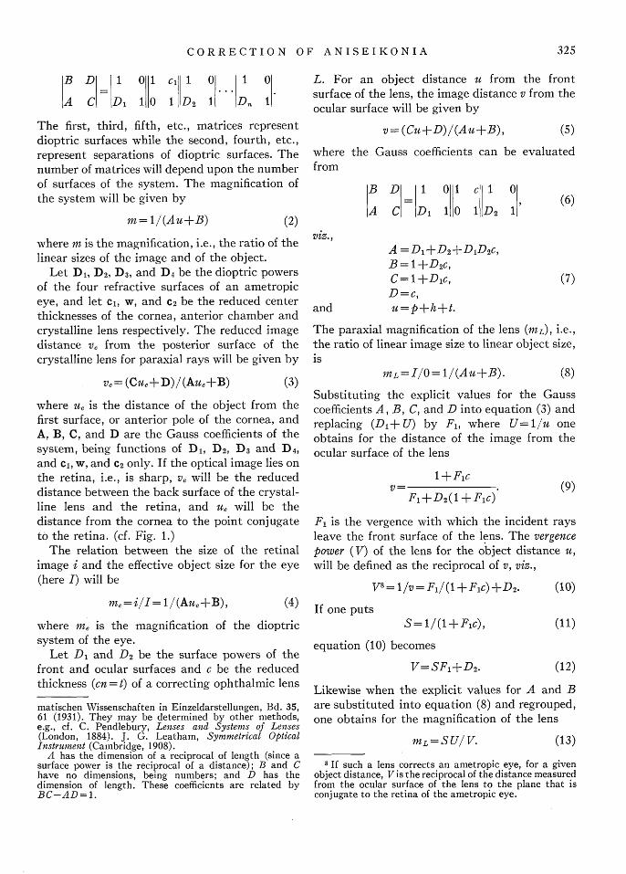
In the following study of aniseikonia, the firststep is to obtain some quantitative relationsbetween the linear size of the object and thelinear size of the image upon the retina of acorrected ametropic eye. For the present it willbe assumed that the eye is fully corrected, i.e.,the dioptric image is sharply formed on theretina. This analysis must then include theproperties of the correcting lens. Fig. 1, representsan ametropic eye (in this case hypermetropic)which is directed toward an object 0, that lies adistance p (meters) from the cornea of the eye.The ametropia is corrected by a lens L, whose
4 The term "retinal image" as used here, describes thatsection of the bundle of image forming rays in the vitreoushumor of the eye which falls upon the retina, and to whichthe retinal elements respond.
FIG. 1. Diagram used in study of retinal image sizewhen correcting an ametropic eye with a single ophthalmiclens.
ocular surface is a distance h from the pole of thecornea, and which causes an image I of 0 to beformed a distance ue (meters) from the cornea.The position of I on the visual axis will be thatof the point which is conjugate to the retina andi the retinal image of the object will be sharplyformed upon the retina.
The Gauss paraxial ray theory will be used inpreference to any other paraxial theory becauseit readily yields the vertex refraction notationof modern ophthalmic lens practice. Briefly, thattheory states that for any symmetrical opticalsystem, conjugate distances' for an object andits image measured from the first and lastsurfaces of the system respectively, are related by
Auv+Bv-Cu-D=O, (1)
where u is the reduced object distance measuredfrom the first surface of the system;
v is the reduced image distance measuredfrom the last surface of the system; and
A, B, C and D are the so-called Gausscoefficients which are functions of thevarious surface powers6
D1, D2, D3... D., and the reduced sepa-rations,
C1 , C2 , C3 . .C,-I, between the varioussurfaces.
The Gauss coefficients can easily be evaluatedfrom the following matrix formulation :7
'The sign system used is as follows: light is incidentfrom the left; distances are measured from surfaces;distances to left are negative; distances to right arepositive. All separations for purposes of development aretaken negative. A reduced distance is an actual distancein an optical medium divided by the index of refraction ofthat medium.
6 Surface powers are defined by D = (- 1)/r, where r isthe radius of the curve in meters and it is the index ofrefraction.
7 Cf. T. Smith, "The Primordial Coefficients of Asym-metrical Lenses," Trans. Opt. Soc. 29, 170 (1928). M.Herzberger, Strahlenoptik, Die Grundlehren der mathe-
324
CORRECTION OF ANISEIKONIA
B D 1 0 1 c, I 0 1 0
A C Di 1 0 1 D2 1 Dn 1
The first, third, fifth, etc., matrices representdioptric surfaces while the second, fourth, etc.,represent separations of dioptric surfaces. Thenumber of matrices will depend upon the numberof surfaces of the system. The magnification ofthe system will be given by
m= 1/(Au+B) (2)
L. For an object distance u from the frontsurface of the lens, the image distance v from theocular surface will be given by
v= (Cu+D)/(Au+B),
wherefrom
(5)
the Gauss coefficients can be evaluated
B D 1 01 Ci 0
A C D1 110 l D2 1(6)
where m is the magnification, i.e., the ratio of thelinear sizes of the image and of the object.
Let D1, D2, D3 , and D4 be the dioptric powersof the four refractive surfaces of an ametropiceye, and let c, w, and 2 be the reduced centerthicknesses of the cornea, anterior chamber andcrystalline lens respectively. The reduced imagedistance ve from the posterior surface of thecrystalline lens for paraxial rays will be given by
ve= (Cue+D)/(Aue+B) (3)
where ue is the distance of the object from thefirst surface, or anterior pole of the cornea, andA, B, C, and D are the Gauss coefficients of thesystem, being functions of D, D2, D3 and D4 ,and cl, w, and C2 only. If the optical image lies onthe retina, i.e., is sharp, ve will be the reduceddistance between the back surface of the crystal-line lens and the retina, and ue will be thedistance from the cornea to the point conjugateto the retina. (cf. Fig. 1.)
The relation between the size of the retinalimage i and the effective object size for the eye(here I) will be
me=i/I= 1/(Aue+B), (4)
where me is the magnification of the dioptricsystem of the eye.
Let D1 and D2 be the surface powers of thefront and ocular surfaces and c be the reducedthickness (cn =t) of a correcting ophthalmic lens
matischen Wissenschaften in Einzeldarstellungen, Bd. 35,61 (1931). They may be determined by other methods,e.g., cf. C. Pendlebury, Lenses and Systems of Lenses(London, 1884). J. G. Leatham, Symmetrical OpticalInstrument (Cambridge, 1908).
A has the dimension of a reciprocal of length (since asurface power is the reciprocal of a distance); B and Chave no dimensions, being numbers; and D has thedimension of length. These coefficients are related byBC-AD= 1.
A =Di+D2+DlD 2c,B = +D2c,C=1+Dlc,D=c,u=p+h+t.and
(7)
The paraxial magnification of the lens (mL), i.e.,the ratio of linear image size to linear object size,is
mL=I/O= 1/(Au+B). (8)
Substituting the explicit values for the Gausscoefficients A, B, C, and D into equation (3) andreplacing (D1 + U) by F, where U= 1/u oneobtains for the distance of the image from theocular surface of the lens
+FicV=_ _ ,, _ ,- (9)
F1+D2(1 +Flc)
F1 is the vergence with which the incident raysleave the front surface of the lens. The vergencepower (V) of the lens for the object distance u,will be defined as the reciprocal of v, viz.,
(10)V"= 1/v= FI/(1+Fic) +D2.
If one putsS= /(1+Fic),
equation (10) becomes
V=SF,+D2.
(11)
(12)
Likewise when the explicit values for A and Bare substituted into equation (8) and regrouped,one obtains for the magnification of the lens
ML=SU!V. (13)
8 If such a lens corrects an ametropic eye, for a givenobject distance, V is the reciprocal of the distance measuredfrom the ocular surface of the lens to the plane that isconjugate to the retina of the ametropic eye.
325

KENNETH N. OGLE
The ratio of the linear size of the retinal imageto the linear size of the object for the correctinglens and the eye in combination can now befound by multiplying equations (4) and (13), i.e.,
i [Ul I-=M LM. (14)
In sharp imagery these two factors are interde-pendent because the image formed by the lensacts as an object for the eye. This dependencemust be made explicit (cf. Fig. 1), using
ue=v+h= (1+ Vh)/V
and then substituting in (14), whence
0 [1 + V]Au,, + B]
In order that the last factor, here, be a functionof the eye alone, one eliminates Ue by means of(3) and then has
i/0 = (S UP) (D-Bv,), (16)
where 1/P = 1 + Vh and ve is the reduced distancefrom the posterior surface of the crystalline lensto the retina, i.e., the reduced depth of thevitreous humor. If the right-hand member ofequation (16) is multiplied and divided throughby p, the distance from cornea to visual object,then the equation becomes
i r rD-Bvel-=[SUpP][ B (17)
Now the factorM=SUpP (18)
may be written as the product ofponent magnification factors, viz.,
M= SLP, 0
three com-
P= 1/(1 - Vh), which will be called thepower factor,
V= V0 -S"2/(U+SOC), which will be de-fined as the vergence power of thelens for the object distance u(u = p - h - t) (this is identical withvertex power when p becomes verylarge)
and V= SoD,+D2 is the vertex (back focal)power of the lens.
This magnification factor is then equivalent tothat for the paraxial angular magnification of anysingle lens when referred to a specified point onthe axis. The point in this case is the pole of thecornea. Thus the ratio of the sizes of the retinalimage and of the object for a fully corrected eyemay be written
i/0 = ME, (20)
where M is a function of the corrective lens= (S0LP), E is a function of the diop-tric constants of the eye = (D - Bve) /P.
Equation (20) and subsidiary relations are thefundamental paraxial ray statements for theangular magnification and power of all singleophthalmic lenses. Their importance will becomemore apparent in the following discussions.
(b) Other formulations
The particular formulation given above for thesize of the retinal image to that of the object forthe corrected ametropic eye, as previouslystated, is not the only one. The object and imagerelations as well as the magnification relation canbe referred to any pair of conjugate points of thesystem, whose magnification ratio m is known ordeterminable. These relations are
(19) and
where S.= 1/(1 -Dic), which will be called theshape factor,"
L=p/(u+S 0 c), which will be called thedistance factor,
I Though this division of the magnification into factorsfor the eye and correcting lens is the most straightforwardfrom the point of view of geometrical optics, it is not theonly one, as will be shown later.
10 Here , c, It and u are taken positive.11 This factor is designated the "effectivity factor," by T.
Smith. Cf. Trans. Opt. Soc. 26, 31 (1924).
s'-=n 2s/(1 +mAs)
me=rm/(1+mAs),
(21)
(22)
where s and s' are the object and image distances,respectively, measured from conjugate pointswhose magnification ratio is M.12 A is the powerof that system (the first Gauss coefficient).When used in the above derivation the dependent
12 These relations, easily found by applying the Gausstheory to the object and image distances referred to asecond pair of conjugate points, are identical with thevergence equations of A. Gullstrand. Cf. Helmholtz,Physiological Optics, Eng. Trans., Vol. I, p. 277ff.
326
CORRECTION OF ANISEIKONIA
relationship between the ophthalmic lens and theeye is
s = (1/ V) +h,
where - h. is the distance from the ocular surfaceof the ophthalmic lens and the first or objectpoint of the reference conjugate points. Thenthe relation between retinal image size andobject size would follow (cf. Eqs. (13) and (16)):
i/O = (S0LP2) (s'/mp ), (23)
where L and P, are the distance and powermagnification factors of the lens magnificationreferred to the first reference point, whence again
i1/ = MET. (24)
Only the conjugate points for three particularcases need be mentioned viz.,
(a) The principal points of the eye, when m = 1.(b) The nodal points of the eye, when m = n/n',
n and n' being the indices of refraction ofair and the vitreous humor, respectively.
(c) The entrance and exit pupils, or stop points.
From a theoretical point of view, in sharpimagery, no single pair of reference points offersadvantages. Calculation through lenses and aschematic eye entails nearly the same amount ofwork.
The selection of the principal points has theadvantage that object distances are moreaccurately expressed as vergences relative to theeyes. The selection of nodal points offers anadvantage in geometrical construction. Both setsnecessitate linear measurements to fictitiousmathematical points. Entrance and exit pupils3
however, have a special property which makestheir selection important.
(c) Formulation for blurred imagery
In practice, it is difficult to determine whetheror not the images on the retinas are actuallysharp. Moreover to what extent an image canbe blurred and good acuity still be obtained orwhat effect the blurring itself has upon the
13 The entrance pupil of the eye is the image of the realpupil formed by that part of the dioptric system whichlies between the real pupil and the object. The distance ofthe entrance pupil from the pole of the cornea can bemeasured by means of a corneal microscope. The exitpupil will be the image of the real pupil formed by thatpart of the dioptric system lying between the true pupiland the retina.
Hz I I -Pi IS-
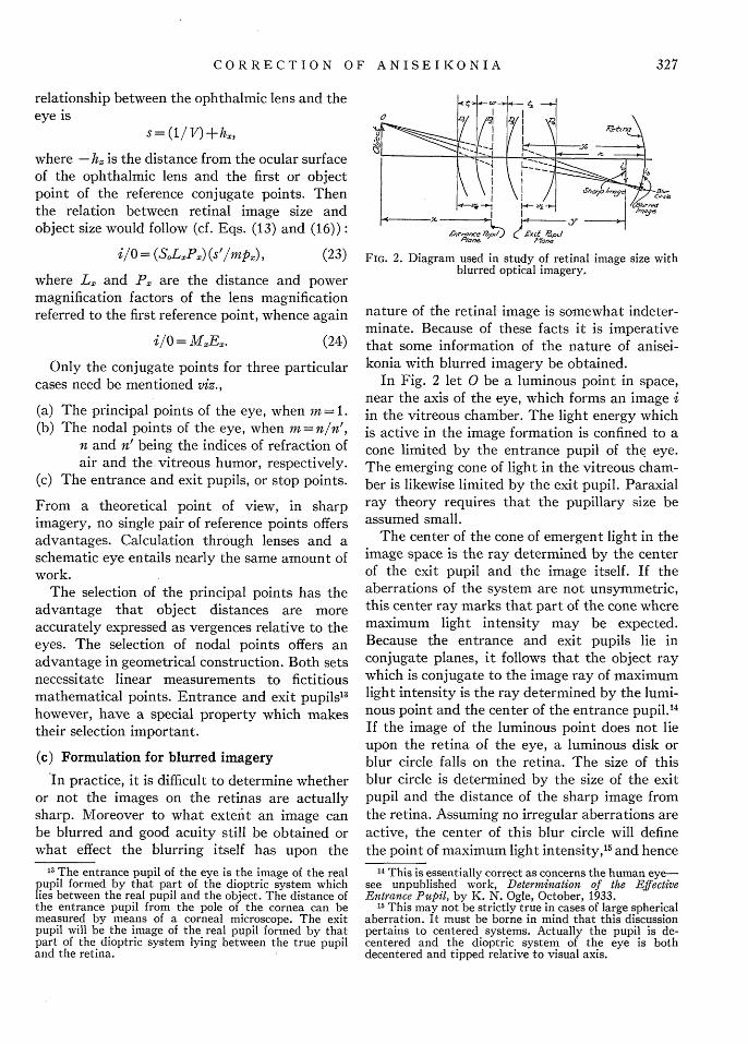
eZ - y;A1W.n-/, ID x R/,pdFIG. 2. Diagram used in study of retinal image size with
blurred optical imagery.
nature of the retinal image is somewhat indeter-minate. Because of these facts it is imperativethat some information of the nature of anisei-konia with blurred imagery be obtained.
In Fig. 2 let 0 be a luminous point in space,near the axis of the eye, which forms an image iin the vitreous chamber. The light energy whichis active in the image formation is confined to acone limited by the entrance pupil of the eye.The emerging cone of light in the vitreous cham-ber is likewise limited by the exit pupil. Paraxialray theory requires that the pupillary size beassumed small.
The center of the cone of emergent light in theimage space is the ray determined by the centerof the exit pupil and the image itself. If theaberrations of the system are not unsymmetric,this center ray marks that part of the cone wheremaximum light intensity may be expected.Because the entrance and exit pupils lie inconjugate planes, it follows that the object raywhich is conjugate to the image ray of maximumlight intensity is the ray determined by the lumi-nous point and the center of the entrance pupil. 4
If the image of the luminous point does not lieupon the retina of the eye, a luminous disk orblur circle falls on the retina. The size of thisblur circle is determined by the size of the exitpupil and the distance of the sharp image fromthe retina. Assuming no irregular aberrations areactive, the center of this blur circle will definethe point of maximum light intensity,'" and hence
14 This is essentially correct as concerns the human eye-see unpublished work, Determination of the EffectiveEntrance Pupil, by K. N. Ogle, October, 1933.
1 This may not be strictly true in cases of large sphericalaberration. It must be borne in mind that this discussionpertains to centered systems. Actually the pupil is de-centered and the dioptric system of the eye is bothdecentered and tipped relative to visual axis.
327
KENNETH N. OGLE
the point of effectivity. The distance from theaxis of the system to the center of the blur circlewill be taken as the size of the blurred image.The nature of aniseikonia with blurred imageryreadily follows.
Since the entrance and exit pupils (or stoppoints) are conjugate points of the ocular system,the image Eqs. (21), (22) and (23) are applicable.
If y is the reduced distance from the plane ofthe exit pupil to the sharp image in the vitreoushumor for a partially corrected ametropic eye,the ratio of the size of this image to the objectwill be (23)
i/O = (SoLPc) (y/mpe),' (25)
where the terms have the meanings given aboveand where the subscript e indicates that theimplicit distances involved are measured fromthe entrance pupil; in is the magnification ratioof the entrance and exit pupils (a function of thedioptric constants of the eye).
The size of the blurred image on the retinarelative to the sharp image will be given by
ibli = Y°,1Y, (26)
where yo is the reduced distance from the exitpupil to the retina. The size of the blurred imageon the retina relative to the same object sizeabove will be given by multiplying Eq. (25) by(yo/y). One obtains
ib/O = (SoLceP) (y0/inpC) (27)or ib/O = ILEb,
where ML is the angular magnification of thelens referred to the entrance pupil ofthe eye
and Eb( =y0 /np,) constitutes the ocular diop-tric part of the retinal image magnifica-tion analogous to the factor E (page 326)for the sharp imagery detail.
In comparing the relation for sharp imagery(Eq. (19)) and that above, it must be bornein mind that in sharp imagery there is a strictdependent relationship between the dioptric fac-tor (1/(1 - Vh)) and the dioptric factor (Bv-D)in a given eye, whereas in the expression abovethe two factors may be quite independent. Itdoes not furnish a criterion as to the nature oramount of blur in each eye. If the magnitude ofV is such that the ametropia becomes completely
X/,,,
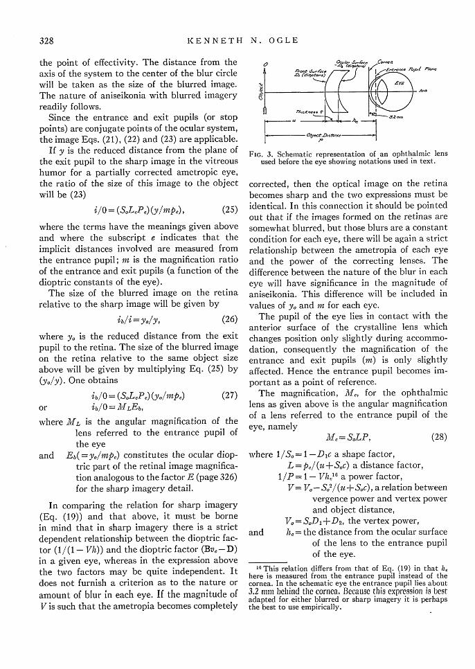
FIG. 3. Schematic representation of an ophthalmic lensused before the eye showing notations used in text.
corrected, then the optical image on the retinabecomes sharp and the two expressions must beidentical. In this connection it should be pointedout that if the images formed on the retinas aresomewhat blurred, but those blurs are a constantcondition for each eye, there will be again a strictrelationship between the ametropia of each eyeand the power of the correcting lenses. Thedifference between the nature of the blur in eacheye will have significance in the magnitude ofaniseikonia. This difference will be included invalues of yo and m for each eye.
The pupil of the eye lies in contact with theanterior surface of the crystalline lens whichchanges position only slightly during accommo-dation, consequently the magnification of theentrance and exit pupils (in) is only slightlyaffected. Hence the entrance pupil becomes im-portant as a point of reference.
The magnification, Me, for the ophthalmiclens as given above is the angular magnificationof a lens referred to the entrance pupil of theeye, namely
Me = S0LP, (28)
where 1/So= 1 -D c a shape factor,L = p,/ (it + 80c) a distance factor,
1/P= 1- Vhll6 a power factor,V= VO-S0
2/(u+Sc), a relation betweenvergence power and vertex powerand object distance,
V0 =S0 D1 +D2 , the vertex power,and h, = the distance from the ocular surface
of the lens to the entrance pupilof the eye.
1" This relation differs from that of Eq. (19) in that hehere is measured from the entrance pupil instead of thecornea. In the schematic eye the entrance pupil lies about3.2 mnin behind thc cornea. Becausc this expression is bestadapted for either blurred or sharp imagery it is perhapsthe best to use empirically.
328

CORRECTION OF ANISEIKONIA
Cf. Fig. 3. In these relations the signs of t, h and pare reversed so that the first two are positive andp becomes positive for reat distances of the objectbefore the eye.
The general relation for the angular paraxialmagnification of a single ophthalmic lens, asgiven by Eq. (28) can, by eliminating the ver-gence power, be written
M = SoPoLo,
where So = 1/(1 -Dic), shape factor,
P0 = 1/(1 - Vh), power factor,
P
(29)
p +h(S"2P_ 1) -t((n- S,) /n)'
distance factor,'
V0 = S0D,+D2, the vertex power, diopters.
The object distance from the reference pointtaken positive, is designated p; h is the distancefrom the reference point to the ocular surfaceof the lens; DI and D2 are the front and ocularsurface powers, and c is the reduced thickness,being equal to t/n, where is the axial thicknessand n the index of refraction. This particularformulation obviates the necessity of computingthe vergence power of the lens and is in generalmore suitable for calculation purposes. The onlyunavoidable and undesirable feature is that thedistance factor LO includes both the shape andpower factors.
The shape factor, S, will vary from zeropercent for a lens with a plano front surface to3.25 percent for a lens with a 16 diopter frontsurface and 3 mm thickness. The distance factorusually will vary from zero for large visualdistances to a few tenths of a percent for readingdistances. The power factor will amount to about1.5 percent per diopter of power of the correctinglens.
III. ANISEIKONIA
Aniseikonia being defined as an anomaly of thebinocular visual function in which a differenceexists between the sizes of the ocular images ofthe two eyes, one should find analytically therelation between the ocular image size and
17 If V =0, D 1=0, Lo =angular magnification of planeparallel of thickness t mm.
linear retinal image size and finally the relationbetween the sizes of the ocular images of the twoeyes. Since the ocular image is the result of asubjective impression, it is apparent that itsabsolute size cannot be determined. However, ifit were possible to measure the ocular image sizeone could compare that size with the size of theretinal image and write
i'=ki, (30)
where i' is the size of the ocular image;
i is the size of the corresponding retinalimage; and
k is the constant of proportionality.While k, for one eye, need not beconstant for all conditions underwhich the eyes may be used, it isreasonable to suppose that for anyfixed condition of the eyes in binocularvision k does not vary.
Thus for the same sized object, one can write thatthe ratio 8 of the sizes of the ocular images of thetwo eyes compared to that of the retinal imagesof the two eyes is
ii2 k i -J-I_ = = a_i2' k2i2 - - i
(31)
where a= k/k 2 is the ratio of the constants ofproportionality between ocular image sizes andretinal image sizes. The ratio [a] is a measure ofthat difference in size between the ocular imagesdue to physiological and anatomical differencesin the visual apparatus of the two eyes. Thisquantity has reality and can, under certainconditions be measured. In a given pair of eyeswhere a] #1, even if the retinal images wereequal in size, a difference would exist betweentheir apparent sizes. The ratio [a] may be desig-nated a "basic aniseikonia." There is no reasonfor assuming that [a] is the same for all cor-responding parts of the two retinas. For thepresent discussion it will be necessary, however,to assume its constancy for any given positionof the eyes, and for paraxial rays.
1 Comparing the ocular images in any other mannerexplicitly involves the absolute magnitude of one of theks. The ratio permits one to compare the sizes inpercentages.
329

KENNETH N. OGLE
From Eq. (20) above, it follows that for avisual object of size 0, at a distance p from thecornea, viewed by a fully corrected eye, the sizeof the retinal image would be
i = MEO,
where M = SOLP a magnification expression beinga function of the correcting lens only andE= (D-Bv)/p a magnification expression forsharp imagery, being a function of the constantsof the ametropic eye only or E = y./m for blurredimagery. Thus, for the two eyes viewing thesame object in binocular vision the actualretinal image sizes will be
ii = ME 10 32and i2 = M2E20. (3)
The ratio of the actual sizes of the retinal imagesof the object 0, upon the two retinas will be
i2 M2E2 1112-[] (3
where d expresses the ratio of El to E2 . Butbecause of the anatomical and physiologicalvisual differences, i will appear to the individualto be of different size than i2 according to
i2' M2t2 L tt IL J (34)
The ratio of the sizes of the ocular images,il'/i 2 ' is designated the eikonic ratio, Ro, and canbe measured on a testing instrument.
It must be clear that in sharp imagery, theexact magnitudes of Ml and M2 and hence theirratio will differ, depending upon the particularpair of points in the eye selected as referencepoints from which object and image distancesare measured. In all cases, however, irrespectiveof the mathematical formulation, or referencepoints selected in a given pair of eyes, the ratioof image size to object size will be
i/0= (ME),
where M and E refer to component magnificationfactors. For any given corrected ametropic eye,(ME) will be a constant quantity. If, in theformulation, M, the magnification of the cor-
19 As would be the case in the testing instrument.
rective lens, be changed through a change in thereference system, the ocular magnification, E,must change inversely. While the magnitude ofthe eikonic ratio (R0) has reality, the ratio of Mlto M2 will depend upon the reference pointschosen. Only the ratio
EMl E'
M2 E2
is real. Therefore the ratio of the magnifications ofthe ophthalmic lenses or test lenses alone has noinherent meaning so far as aniseikonia is con-cerned. The significance of the ratio appears onlywhen the equivalent iseikonic prescription isdetermined, (Eq. (46)). It is necessary that thesame reference points be used in designatingboth the magnifications of the test lenses andthose of the ophthalmic iseikonic lenses.
This discussion pertains only to the case inwhich sharp images are maintained on the retinasof the two eyes. Then the choice of referencepoints is arbitrary. However, if by any chanceerrors occur in the correction of the ametropia,the images will be blurred. Then there is onlyone pair of reference points which is strictly valid,namely the entrance and exit pupils. This re-striction arises from the very nature of imageformation and is not dependent on the method ofanalytical description. In sharp imagery any pairof points may be selected for reference, but forblurred imagery the entrance and exit pupilsmust be used. Therefore the latter, which will becorrect for either sharp or blurred imagery, arethe advantageous points to select for all generalformulation.
It should be pointed out here that in certaincases, the ratio of the sizes of the ocular imagesalone will not define all the incongruities betweenthe ocular images. For example, the change indeclinations introduced by meridional iseikoniccorrections whose axes are oblique, presentsadditional problems not entirely included in theratio comparison.
IV. Two ELEMENT CORRECTING LENS SYSTEM-
TRIAL CASE LENSES
In the clinic a patient's ametropia is correctedby means of trial case lenses, which consist ofspherical and cylindrical lenses made in con-
330
CORRECTION OF ANISEIKONIA
venient steps of power. The spheres are usedto determine the amount of spherical ametropiaand the cylinders to determine the amount andaxes of astigmatism. Quite generally in a givenexamination both a spherical and a cylindricallens will be needed before each eye to fully cor-rect the ametropia present. Therefore the powerand magnification relationships for a two elementlens system are necessary for an understandingof the correction of aniseikonia.
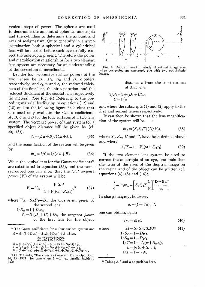
Let the four successive surface powers of thetwo lenses be D, D2, D3 and D4 dioptersrespectively, and c, w and 2 the reduced thick-ness of the first lens, the air separation, and thereduced thickness of the second lens respectively(in meters). (See Fig. 4.) Referring to the pre-ceding material leading up to equations (12) and(18) and to the following figure, it is clear thatone need only evaluate the Gauss coefficientsA, B, C and D for the four surfaces of a two lenssystem. The vergence power of that system for aspecified object distance will be given by (cf.Eq. (5)),
Vt= (Au+B)/(Cu+D), (35)
and the magnification of the system will be givenby
mL=I/0= 1/(Au+B). (36)
When the equivalents for the Gauss coefficients2 0
are substituted in equation (35), and the termsregrouped one can show that the total vergencepower (Vt) of the system will be
V1S0 22
Vt= Vo2+ 211 + V1(w+So2c2 )
(37)
where V 2= S S 2D3+D4 , the true vertex power ofthe second lens,
1/S2 = 1 +D3c2 ,V1 = S,(D,+ U) +D2, the vergence power
of the first lens for the object
20 The Gauss coefficients for a four surface system areA = A12 (1 +D 4 C2 ) +A 34(l +D1ci) +A 12A 34w,
A12 =D, ±D+DiD2c,A34 =D3+D4+D3D 4c2,
B = (1 +D2 C) (1 +D4 C2) + (c1+w(1 +D2C1))A34,C= c2A 12+ (1 +Dici) (1 +D3c2) +A 12W(1 +D3C2),D = (1 +D2C)C 2+C1(1 +D3C2) + (1 +D3c2) (1 +D2cl)w.
21 Cf. T. Smith, "Back Vertex Powers," Trans. Opt. Soc.,26, 35 (1924), for case when U=O, i.e., parallel incidentlight.
0 Ir
(' hA
I
it
FIG. 4. Diagram used in study of retinal image sizewhen correcting an ametropic eye with two ophthalmiclenses.
distance u from the front surfaceof that lens,
1/Si= 1+(D1+ U)ci,U=1/u
and where the subscripts (1) and (2) apply to thefirst and second lenses respectively.
It can then be shown that the lens magnifica-tion of the system will be
mL= (S1S, 2T)(U/Vt), (38)
where Si, S,2, U and Vt have been defined aboveand where
1/T= 1+ V1(W+S,2C 2). (39)
If the two element lens system be used tocorrect the ametropia of an eye, one finds thatthe ratio of the sizes of the dioptric image onthe retina and of the object can be written (cf.equations (4), (8) and (14)),
i - U[ D-BVe-= memL = SlSo2.0 Ue
In sharp imagery, however,
Ue= (1+ Vh)/V,
one can obtain, again
i/O = ME,
where M= SoSo2TLP,22
1/S.1= 1-Dic,1/So2= -D3c2,1/T= 1- V1(W+S0 2c2),
L=p1(u+Sc),1/P = - Vh,
(40)
(41)
h and u as positive here.
- - - -
331
I - �2111 �
22 Taking c,

KENNETH N. OGLE
where V, the total vergence power of the twolenses for the distance it, is given in Eq. (37).
V, = S1(D1- U) +D2,
1 30 1 uGSi, ==
1-(D 1-U)cl u+S0 1cl
U= 1/u, u=p-h-tl-t 2 -w,
V1 = Vo1 l-U+S 0icl
Vl= SlD1+D2,
V02 = 8 2D3 +D ,
and where again E=(D-Bv,)/p a function ofthe dioptric constants of the eye.
V. THE RELATION BETWEEN THE MAGNIFICATION
PROPERTIES OF THE TEST LENSES AND
THOSE OF THE SPECTACLE LENSES IN
THE CORRECTION OF ANISEIKONIA
(a) Eikonic condition
When the patient is tested in a clinical instru-ment and the refraction in both eyes has beenbalanced with certain test lenses, the differencebetween the sizes of the ocular images in variousmeridians can be corrected, and hence measuredby special iseikonic lenses. This measurement forany given meridian specifies the eikonic ratio R0described above, viz.,
RO=[ | d a (42)
The actual procedure in making the measure-ments in the clinical instrument, of course, con-sists in modifying the ratio of the magnificationsof the test lenses by means of special size lenseswhich are added before one or the other of theeyes until the ocular images appear equal. Then
R2' dM2] [la = 1, (43)
where R is the ratio of the magnifications of themodifying lenses. Clearly
Equation (43) correctly describes the ocularimage size ratio for any type of lenses used withthe eyes, consequently it describes the conditionwhen either test or spectacle lenses are used.Inspection shows that Ml and M2, which desig-nate the magnification properties of ophthalmiclenses, can be adjusted by careful selection ofthe shape and thickness of the individual lensesso that the ocular images will be equal, i.e.,
- I ld I = 1a .i2' LIVI2 JS t
(45)
This equation states the necessary condition thatcorrective ophthalmic spectacles be iseikonic.This condition must be satisfied in all meridians.
It is simple now to state the necessary condi-tions for determining the equivalent iseikonicprescription. From these the spectacle lenses canbe designed and manufactured which correctaniseikonia and ametropia for a given prescrip-tion. For any meridian Eqs. (42) and (44) mustbe identical. Thus one obtains the statement ofiseikonic equivalence,
- = RM1/2 s M2 e
(46)
where the subscripts e and s refer to the clinicaltest lenses and spectacle lenses respectively.This relation will be referred to as the iseikoniccondition necessary for the design of the equiva-lent iseikonic prescriptions.
(b) Differential magnification properties
It is not necessary to deal with the total mag-nifications, but with the differential part of themagnifications between the spectacle lenses andthe lenses of the clinical instrument. If one sub-stitutes the component factors for the magnifica-tions of Eqs. (41) and (22) for the single (spec-tacle) and double (trial case) lenses into Eq. (46),one has for a given meridian,
(S0 LP) 1 (SolS 0 2TLP) 1
(S0LP) 2 (S01S02 TLP) 2 Je(47)
R= 1/R_.23 (44)
23 In general R differs from unity by a few percent, and ithas been convenient to express R as R = 1 +e, and refer tothe percent eikonic difference, viz., lOOe.
In order that the ametropia be corrected byboth trial case lenses and spectacle lenses, thevergence power must be made the same for
332

CORRECTION. OF ANISEIKONIA
each eye. Since the P magnification factor isdefined by
1/P = 1-Vh,where V is the vergence power and h is thedistance from the entrance pupil to the ocularsurface of the correcting lens, the P factors forthe spectacle lens and trial case lenses for thesame eye will differ only by the difference in h inthe two cases. In general the h for a spectaclelens will differ from he for the test lens by a smalldistance (h), where
hs=he+Ah. (48)
Equation (47) can be divided through by Pi/P2]e,and one obtains
(S0 LP') 1 (S, 1S, 2TL)1 (R 2 (49)
(S0LP) 2]: (S.IS. 2TL)2J
where1
P= - ,1 -V(A'h)
when (h) is small.One can further reduce the total magnification
by multiplying the L factors on both sides of Eq.(47) by pp where p is the object distancemeasured from the ocular surface position of thetrial case lenses, i.e.,
P=Po+he. (50)
One then defines the differential paraxialangular magnification of a single ophthalmiclens, as
Ma = SLP', (51)
S= 1/(1 -Dic),L= p0 /(u+Sc),P' = 1/(1- V(Ah)),u = -t-Ath.
must be identical in all meridians for the sameeye, thus one has for the statement of ametropicequivalence,22
(Vi) =(V1)"/(P1 )( V2) s = ( V2) e/ (P2 ') .
(52)
Equations (46) and (52) state the necessary con-ditions for the design of the lenses for the equiva-lent iseikonic prescription in any specifiedmeridian.
(c) Cylindrical lens excess magnificationsFrom what has been written above concerning
the eikonic condition, e.g., Eq. (49), it is clearthat the magnifications needed in the test instru-ment to equalize the sizes of the ocular images(expressed by R), are not a simple measure of theaniseikonia present, because of the magnificationproperties of the test lenses. These magnificationsare unavoidable and are variable and of con-siderable magnitude. They will be dealt withspecifically. A redesign of the trial case lensesmay simplify these magnifications.
In testing the ametropia with standard trialcase lenses set it is common practice to place thespherical refractive lens nearest the eye and thecylindrical refractive lens farthest from the eye.Obviously it is an advantage, to have the powerof each cylinder so marked that its effectivepower is directly additive to the power of anysphere. Then, with any combination of sphere andcylinder the total effective power can be easilyfound by simple arithmetic. Inspection of Eq.(37) indicates the manner in which this may bedone. For distant vision when the test distancebecomes great, the total effective vertex powerVo (diopters) becomes
V0 1So3 sVt= V2+1 +
1 - Vl(W+S.s62)(53)
In general the greater part of the total angularmagnification of an ophthalmic lens of any poweris due to the P factor magnification. Hencedifferential magnification deals with smallerquantities and indicates more directly the mag-nification characteristics of the ophthalmic lens.
The vergence powers of the ophthalmic lenses2 4
and the vergence powers of the trial case lenses
24 Referred to the points before the eyes at which thevergence powers of the trial case lenses were specified.
where now V is the vertex power of the cylin-drical lens. The powers of the cylinders andspheres can be made additive if the markedpower, V1', of the cylindrical lens be defined by
VlV01S. 2
(54)1- V01(w+Sosc2)
25 These relations follow since the positions of the imagesformed by the spectacle lenses must be the same as werethe positions of the images formed by the correspondingtrial case lenses.
333
where
KENNETH N. OGLE
Then for distant vision
Vo I = Vo2 + VO1. 26 (55)
Inspection will show, however, that if any cylin-drical correcting lens be added to any sphericalcorrecting lens and the total effective power beaccurate, the front curves and thicknesses for allthe spherical lenses must be the same.
When trial case lenses manufactured in thismanner are used in testing aniseikonia, the shapefactor S 2 in Eq. (49) is always the same andhence will drop out of the ratio of the magnifica-tions of the trial case lenses (Eq. (49)). Theremaining quantity for each cylindrical lensN= S0 LT, remains.2 7 This quantity, N, desig-nated as the cylindrical excess magnification,depends only upon the particular trial case cylin-der used in the testing instrument. It is an un-wanted magnification factor which may arti-ficially create a difference in size between theocular images in the power meridian of eachcylindrical trial case lens used. The eikonic ratioas determined in the clinic cannot then indicatethe true aniseikonia. Under certain circumstancesit is possible28 to design a trial case system the useof which would eliminate this factor. In such acase the ratio between the ocular images asmeasured in the clinic would have quantitativesignificance regarding the amount of aniseikoniaand would facilitate the design of the equivalentprescription lenses.
VI. TYPES OF CORRECTION
In general it has not been feasible or practicalin the clinic, to measure aniseikonia in allmeridians and the measurements have beenlimited to the vertical and horizontal. Thesemeridians in which aniseikonia has been meas-ured in the clinic are designated eikonic meridians.
26 This additive property is found in most of the trialcase sets manufactured today.
27 The L factor is unity for distant vision and hence doesnot enter into the cylindrical excess magnification. Ifcylindrical lenses are included before both eyes in thetest, even though one is of zero power, the L factor dropsout of the eikonic trial case lens ratio.
28 One means for doing this is to design the shape of thecylindrical lens for distant vision so that its shape factorSol just offsets the T factor, i.e., Sol T= 1. A different set ofcylinders would be required for near vision unless cylindricallenses are always placed before both eyes (though one maybe of zero power).
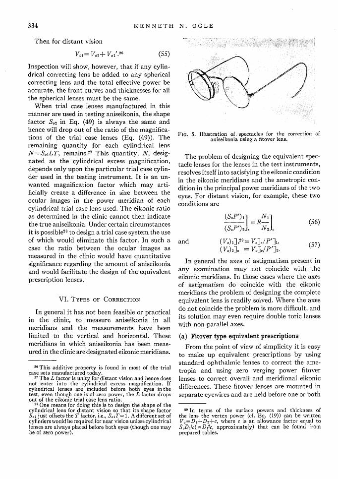
FIG. 5. Illustration of, spectacles for the correction ofaniseikonia using a fitover lens.
The problem of designing the equivalent spec-tacle lenses for the lenses in the test instruments,resolves itself into satisfying the eikonic conditionin the eikonic meridians and the ametropic con-dition in the principal power meridians of the twoeyes. For distant vision, for example, these twoconditions are
(Sl0P')1 N 1 1I =R- I (56)
(SoP')2 N 2 c
and (V.) ]1 V29= ]e/P11,
(IVo)2]s = VoeI/P 12(57)
In general the axes of astigmatism present inany examination may not coincide with theeikonic meridians. In those cases where the axesof astigmatism do coincide with the eikonicmeridians the problem of designing the completeequivalent lens is readily solved. Where the axesdo not coincide the problem is more difficult, andits solution may even require double toric lenseswith non-parallel axes.
(a) Fitover type equivalent prescriptions
From the point of view of simplicity it is easyto make up equivalent prescriptions by usingstandard ophthalmic lenses to correct the ame-tropia and using zero verging power fitoverlenses to correct overall and meridional eikonicdifferences. These fitover lenses are mounted inseparate eyewires and are held before one or both
29 In terms of the surface powers and thickness ofthe lens the vertex power (cf. Eq. (19)) can be writtenV 0=D1+D2+e, where e is an allowance factor equal toS0 D12 c(=D 2 c, approximately) that can be found fromprepared tables.
334

CORRECTION OF ANISEIKONIA
spectacle lenses by spring-clips (Fig. 5). Thismethod is especially suitable for those cases ofoblique astigmatism where the astigmatic axes donot coincide with the eikonic meridians. Themethod is also suitable for the clinic where trialprescriptions may be needed. Tables can be pre-pared in which the magnifications in the principalmeridians of each ophthalmic lens are listed. Toavoid an allowance for the cylindrical excessmagnifications it is convenient to define the mag-nification in each principal meridian as enteredin the table as (cf. Eq. (56))
M'= SoLP'/N. (58)
In cases of oblique astigmatic axes it is necessaryto find the magnification components in theeikonic meridians. Then the equivalent prescrip-tion in each eikonic meridian must be satisfied by
M1'1/12'],F=R, (59)
where M1' and M2' are the magnifications of thetwo lenses defined by Eq. (58); F is the fitoverzero verging power lens correction and R is theratio of the iseikonic test lenses used in a givenexamination to equalize the ocular images. Interms of percent magnification the above rela-tion states that the difference between the differ-ence in size of the ocular images as measured inthe clinic and the difference of the magnificationsas defined by Eq. (58) of the standard correctingpower lenses is corrected by suitable fitoverlenses.
(b) Unitary prescriptions
The fitover type spectacles are not alwaysdesirable, however, because of their excessiveweight, difficulty to keep clean, and for cosmeticreasons; hence lenses are desired which includeboth ametropic and aniseikonic corrections, i.e.,unitary lenses. From the above theory the im-portant means available to meet the eikoniccorrections are:
(1) Bending, or altering the shape of the lenses,by varying the front surface power.
(2) Changing the axial thickness.(3) Varying the distance of the lens from the eye.
It is possible to select the curves, thicknesses andpositions for the two corrective lenses to duplicate
any measured eikonic ratio, provided that ratiois not too large. Where the eikonic ratio is differ-ent in the two eikonic meridians this requires abi-toric lens, and the means of obtaining differentmagnifications are limited, since (2) and (3)above must remain the same for both.
Inspection of Eq. (49) shows that some simpli-fication of design can be obtained if the spectaclelenses are mounted before the patient's eyes sothat the ocular surfaces are the same distancesfrom the eyes as were the corresponding trial caselenses in the clinical instrument. Then Ah=0,and the power factor (P') in the magnificationdisappears.3 0 In general the method is not fea5-ible, because of practical problems in fittingspecial type frames, or in designing excessivelythick lenses.
At present it is practical to specify the positionof the spectacles before the patient's eyes by thedistance from the pole of the cornea to the centerof the eyewire of the frames. From the point ofview of the equivalent lens design this compli-cates the problem since (h) is usually unknownbeforehand. Its magnitude depends upon thelens shape, thickness, and size and the nature ofthe bevel. Various technical means are available,however, for solving the problem, but cannot beconsidered here.
In many cases when the eikonic ratio is large orquite different in the principal meridians, doubletcorrecting lenses may be necessary. These doub-lets act as airspaced telescopic units but includethe refractive correction. They may be designedto fit into ordinary eyewires. They provide ameans for obtaining higher overall and meridionalmagnifications than can be obtained practicallywith single lenses.
VII. ZERO VERGING POWER ISEIKONIC LENSES
It is sometimes convenient to refer to the"verging power" of an ophthalmic lens in de-scribing its power behavior in a given case. By"verging power" will be meant the change in thevergence of incident light caused by the power ofthe lens. It must refer to a specific object dis-tance. It is defined algebraically as
V= V+1/(p-), (60)
30 Dr. E. D. Tillyer first pointed out this simplification.
335

KENNETH N. OGLE
where V is the verging power for a given objectdistance (diopters),
V is the vergence power for the samegiven object distance,
p-h is the distance from the object tothe ocular surface of the lens.
Were the lens infinitely thin the verging powerwould be identical with the vertex power, as canbe seen by substituting the equivalent expressionfor the vergence power cf. equation (60) above.If the incident light is from an infinitely distantobject, the verging power is identical with thevertex power. A lens which has zero vergingpower for a given object distance is one in whichthe emergent light has the same vergence as theincident light, i.e., the position of the image of anobject formed by the lens coincides with that ofthe object itself. Such a lens would usually havemagnifying properties, however.
Zero verging power lenses have played, and areplaying, an important role in the measurementand correction of aniseikonia. These lenses havebeen used for two purposes, namely to measure,in the clinic, the magnitude of aniseikonia andsecond, to correct the aniseikonia found. Cor-rections up to four or five percent overall andmeridional magnification can be had with thesesingle zero verging power lenses. These lensesmay be designed by means of equation (19). Sucha lens for a given object distance p and ocularsurface distance h, will have a vergence powerequal to the reciprocal of the distance of theobject from the ocular surface of the lens, i.e.,V=-1/(p- h), then
p-htM=SoPAp-h-t+SoC
n((M- 1)/M)(p-h) - (n- )t
and D2 =-
t(p-h-t)n(p-h-t) (M- 1) -t(n-1)
(62)
t(p - h)
If such a lens is designed to have zero vergingpower for an infinitely distant object, the designfollows
(63)M=S0 = 1/(1-Dit/n),
whence D1= (M-1)n/Mt
or M= 1 -D2t/n,
D2=-MD1 =-(M-1)n/t.
*Such a lens is independent of h, the distance fromthe cornea. The lenses for the most practical setare designed for a visual distance of 75 cm.
It is clear that a lens can have zero vergingpower for one visual distance only and when usedfor any other visual distance the lens will have asmall amount of verging power. If it be assumedthat the eyes do not change accommodation tomake up for this small amount of power it ispossible to design a lens which has zero vergingpower at one visual distance, but will have thesame angular magnification at all visual dis-tances. The equation stating this condition canbe obtained by differentiating Eq. (19) withrespect to p and equating the result to zero. Thefinal relation, viz.,
h(MS-1 )-(t/n) (n-S0 ) = ° (64)
is independent of p. This relation together withEq. (61) uniquely determines D1, D2 and t forgiven values of p, h and M. One finds for thethickness
S 02 I
VO=S --- ,u+S,,c p- St
where V0 = SoDi+D2.
These two equations contain three unknowns, D1,D2 and t, hence one must be specified.
Arbitrarily specifying the thickness for anydesired lens one can find the front and ocular
surface powers, by solving the two equations forDI and D2. One has
(61) nh(M2- 1) (p-h)(65)
h(M2-1)+p(n-M)
D1 and D2 are found from Eqs. (62).Overall and meridional zero verging power
magnification lenses are needed. In order that themeridional lenses have unit magnification for agiven visual distance in the no magnificationmeridians double saddle-shaped bi-toric lensesare required. The lenses may be ground withpiano surfaces in these meridians, and the result-
336

CORRECTION OF ANISEIKONIA
TABLE I. Zero verging power lenses.Lenses which change the apparent size of the object
without materially changing the vergence of the lightwhich enters the eye. Lenses designed to have
zero verging power for a visual distanceof 75 cm.
Di | D2 VergingMagnifi- Front Rear t Power at
Lens cation Surface Surface Thickness 6 meters inNo. 75 cm Diopters Diopters mm Diopters
1 0.25% +2.43 -2.43 1.20 +0.012 0.50 +5.51 -5.52 1.22 +0.013 0.75 +9.84 -9.89 1.07 +0.024 1.00 +10.17 -10.24 1.39 +0.025 1.25 +10.47 -10.56 1.68 +0.036 1.50 +10.71 -10.82 1.97 +0.047 1.75 +10.89 -11.02 2.26 +0.048 2.00 +11.03 -11.18 2.55 +0.059 2.25 +11.15 -11.32 2.83 +0.05
10 2.50 +11.29 -11.49 3.10 +0.061 1 2.75 +11.38 -11.60 3.38 +0.0712 3.00 +11.49 -11.73 3.65 +0.0714 3.50 +11.68 -11.97 4.18 +0.0816 4.00 +11.82 -12.16 4.70 +0.1018 4.50 +12.03 -12.43 5.18 +0.1120 5.00 +12.20 -12.64 5.66 +0.12
Distance of ocular surface of the lens taken as 25 mm from cornea.it = 1.523.
ant magnifications for the various visual dis-tances can be measured or computed. Thus themagnification error can be corrected in the pre-scription. It is sometimes convenient to usecompensating lenses placed before the other eyein the test instrument which then balances themagnification effect in the piano meridians of themeridional lenses.
In Table I are shown the specifications for atypical set of zero verging power lenses."
VIII. LOGARITHMIC NOTATION
In practice it is convenient to specify themagnification of an ophthalmic lens in terms ofpercent magnification, and refer to the amount ofaniseikonia as a percent difference in size betweenthe ocular images. This notation in the design ofthe equivalent prescription may introduce errors,however, since magnification ratios or productswould be considered as percent differences orsums. Hence the device is used of expressing themagnification as 100 times the natural logarithmof the magnification, written LM. Then differ-
1 These lenses have excellent field properties withnegligible distortion.
ences and sums are not only convenient andaccurate, but are near enough to percentages tohave quantitative meaning.12 Thus the LM valueof an ophthalmic lens is Eq. (19)
LM=LS 0+LL+LP,
where LS, LP and LL are 100 times the naturallogarithm of the S, P and L factors.
The logarithm notation is also convenient inexpressing the iseikonic condition (cf. Eq. (46))for then
LM,]5-LM,], =LR +LM,], -LM2 ],.
It must be remembered that the above theoryis presented from a strict theoretical point ofview, and in many instances approximations canbe made because of certain tolerances allowablein the measurement of aniseikonia and in thegrinding of the finished spectacle lenses.
IX. BIBLIOGRAPHY
0. Henker, "Die Ursachen der zuweilen vorkommendenMisserfolge bei Verwendung durchgebogener Brillen-glaser," Z. f. o. Optik. 5, 13 (1917).
A. E. Glancy, "The Focal Power of Ophthalmic Lenses,"Am. J. Physiol. Optics, 2, 71 (1921).
W. Swaine, "Paraxial Actions of Ophthalmic Lenses,"Trans. Opt. Soc. 24, 79 (1922).
W. H. A. Fincham, "Vertex Power and Its Measurement,"London Opt. Soc. Trans. 27, 203-214 (1926).
H. Erggelet, "Brillenlehre," Kurzes Handbuch derOphthalmologie, ed. F. Schieck und Bruckner, 2, 745(1932).
A. Ames, Jr., Kenneth N. Ogle and Gordon H. Gliddon,"Corresponding Retinal Points, the Horopter and Sizeand Shape of Ocular Images," J. 0. S. A. 22, 538-574 and575-632 (1932).
Kenneth N. Ogle, "An Analytical Treatment of theLongitudinal Horopter; Its Measurement and Applica-tion to Related Phenomena, Especially to the RelativeSize of the Ocular Images," J. 0. S. A. 22, 665-728(1932).
A. Ames, Jr., Gordon H. Gliddon and Kenneth N. Ogle,"Lenses for Changing the Size and Shape of DioptricImages," The Annals of the Distinguished ServiceFoundation of Optometry 1, 61-70 (1932).
M. von Rohr and H. Boegehold, Das Brillenglas alsoptisches Instrument 29-66 (Berlin, 1934).
32 This follows from the series expansion of loge M, i.e.,
loge M=(M-1)-M2(M-1)2++4 (M1)3....
When (M-1)2 is below precision of measurements,(100) loge M is identical with percent magnification.
337