the comparison of gravitational acceleration through
TRANSCRIPT

The Comparison of Gravitational Acceleration
through Optical Sensor and Receptor Pad Apparatus
Nadi Suprapto1, Utama Alan Deta2, Alif Syaiful Adam3, Husni Mubarok4, Abd. Kholiq5
Physics Department
Universitas Negeri Surabaya
Surabaya, Indonesia [email protected], [email protected], [email protected], [email protected],
Abstract—The aim of this research is to compare the
gravitational acceleration based on the two different apparatus
measurement. That two apparatus are similar, use free fall
setting. That difference is in time record method. This
gravitational acceleration determined from metal ball fall’s time
in a predetermined distance, measured by a series of an optical
sensor (first apparatus) and mechanical switch (second
apparatus). In the first apparatus, four pairs of optical sensors
installed in a vertical metal alloy rod at an adjustable interval.
The metal ball dropped by holding an electric magnet placed at
the top of the rod. As the metal ball passes between two sensors,
it interrupts the path of infrared light radiating from each
sensor. In the second apparatus, the dropped ball mechanism is
the same, different in time determination. Two plates are
installed in the bottom of the rod as the mechanical switch, time
will record when the up plate touches the bottom plate because of
the ball’s hit. As the results, the gravitational acceleration from
the first apparatus (optical sensor) is 9.823 ± 0.029 m/s2 and from
the second apparatus (receptor pad) is 10.010 ± 0.025 m/s2.
Keywords—gravitional acceleration; free fall; optical sensor;
mechanical switch
I. INTRODUCTION
Gravitational acceleration measurement has been a scientific interest object in a long time [1]. Many simple and popular techniques have discovered over the years and applied to education purpose, free fall object and simple pendulum. In simple pendulum, gravity constant determines from time period of particular vibrance where related to length while free fall determines from timing of free-falling object. Instead of the data processing, free fall has easier calculation than simple pendulum. It means, this process can be solved without high mathematics skill. Nevertheless, this method can produce the precision result. The gravitational acceleration must be approximated to 9.8 m/s2 [2, 3].
In free fall, the applied force follows the newton second’s law. It means there is more than one force in a free fall metal ball. The gravity force, affect the ball to fall. Besides, the other force, friction force, affect to ball as the consequence of the ball travel’s media in the air. Afterwards, the friction force was neglected because of the very low affect of the metal fall ball. This is supported from the gravity result of this apparatus;
show the gravitational acceleration approximate to 9.8 m/s2. It means, the gravity force become the only force apply to the metal falling ball.
Recently, the gravitational acceleration has determined with same method (free fall). These results are 980.583 22 cm/s2 [4], 9.8012 m/s2 [5] 0.98092 m/s2 [6], and 9.796 m/s2 [7]. Most of them use light emitting sensor [4], IR transceiver [6] and soundcard [7]. All that determination has a good precision, approximate to 9.8 m/s2. However, that technique was either deemed expensive and sometime unsafe, but doesn’t compare to different methods.
Nevertheless, the using of that technique in a basic level, such as undergraduate physics program as the introductory physics, few inadequencys are inevitable. That weakness is caused by the fact that setup need expensive component as experiment apparatus. The other weakness are the technique utilizing, especially the environmental conditioning to obtain a good and precision result. In addition, that utilizing need highly trained person in order to gain maximal result and good maintenance. All that limitation needs more effort to use this technique in laboratory. For the teaching material, to measure the gravitational acceleration, need the simple, economic, easy to use and safe apparatus as a measuring method. It is important to gain more information for variable measurement. Nowadays, this experiment process is the common study activity. In 21st learning process support the experiment process as the processing-orientated activity like problem solving, adapting skills and teamwork [8]. A simple procedure to determine the gravitational acceleration is the pendulum using. The utility of pendulum, measure the period of oscillation and the time measure of the metal ball fall in a particular distance, are the common procedure to determine gravity constant [9, 10]. Although the pendulum method can determine the gravitational acceleration, but it can be affected by other variable such as air resistance (air friction), mass of the rope and uncertainty period measurement, free fall methods have less disturbing variable [11]. That can be minimalized with some conditioning.
This particular research compares the gravitational acceleration with different apparatus, but still economic, safe to use and self-build. The component can find easily around us use alternative component. The different path comes from the
882
Atlantis Highlights in Engineering (AHE), volume 1
Copyright © 2018, the Authors. Published by Atlantis Press. This is an open access article under the CC BY-NC license (http://creativecommons.org/licenses/by-nc/4.0/).
International Conference on Science and Technology (ICST 2018)

metal ball fall’s time determination; first apparatus uses optical sensor and second one uses mechanical switch.
II. METHODS
A. Apparatus Design
Fig. 1. Free fall apparatus using optical sensor
This apparatus consists of many components. As the Figure 1 show above, it builds with 5 main components, including: (1) Holding magnet, (2) Optical sensor 1, (3) Optical sensor 2, (4) Digital counter and (5) Voltage adapter. As the procedure, a metal ball is fired from the holding magnet. This device made from relay and work with magnetic principle. When the button presses in digital counter, the magnetic force was disappeared and made the metal ball fall with no initial velocity. Besides, the rod has a length of about 1 m. It means, the maximum predetermined height is about 1 m. The rod’s width and the ball’s diameter are designed to guarantee that the ball doesn’t touch the wall. Furthermore, the four sensors pairs are precisely located. The first two is located at the middle of the rod and it can adjust freely. The other two sensor is located in the bottom of the rod and it can adjust freely too. From this setting, it supports the dual height manipulation in a same time and it is possible to detect the metallic ball when it passes across each sensor. The two-time counter show in digital counter.
For further explanation, the sensor setting show in Figure 2. This sensor explains the optical sensor 1 and 2 parts. Each optical sensor set, either the optical sensor 1 or 2 consists of a light-emitting diode (LED) and a phototransistor as the
receiver, placed in front of the other on the particular clipper build in the rod. While the infrared radiation from the LED is received to phototransistor, it produces a current through a resistor, gives an output voltage and records the time to show in digital counter.
Fig. 2. Optical sensor
For second apparatus, consists of many components. As the Figure 3 show below, it builds with 4 main components. In succession (1) Holding magnet, (2) Receptor pad, (3) Digital counter and (4) Voltage adapter. The procedure same with apparatus before, a metal ball is fired from the holding magnet. This device made from relay and work with magnetic principle. Besides, the rod has a length of about 1 m and the height adjustment has a gap with receptor pad. It means, the maximum predetermined height more than the first apparatus, but it should in a short height. The rod’s width and the ball’s diameter are designed to guarantee that the ball doesn’t touch the wall. Furthermore, the receptor pad, as the time counters, located in the bottom of the rod. From this setting, it supports just a height manipulation in a same time, not dual as the first setting. It is possible to detect the metallic ball when it touches the receptor pad. The time counter shows in digital counter.
Fig. 3. Free fall apparatus using receptor pad
883
Atlantis Highlights in Engineering (AHE), volume 1
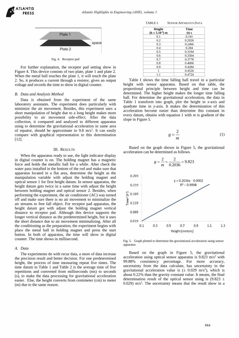
Fig. 4. Receptor pad
For further explanation, the receptor pad setting show in Figure 4. This device consists of two plate, plate 1 and plate 2. When the metal ball touches the plate 1, it will touch the plate 2. So, it produces a current through a resistor, gives an output voltage and records the time to show in digital counter.
B. Data and Analysis Method
Data is obtained from the experiment of the same laboratory assistants. The experiment does particularly with minimize the air movement. Besides, this experiment uses a short manipulation of height due to a long height makes more possibility to air movement side-effect. After the data collection, it compared and analyzed to different apparatus using to determine the gravitational acceleration in same area of equator, should be approximate to 9.8 m/s2. It can easily compare with graphical representation to this determination [12].
III. RESULTS
When the apparatus ready to use, the light indicator display in digital counter is on. The holding magnet has a magnetic force and holds the metallic ball for a while. After check the water pass installed in the bottom of the rod and make sure that apparatus located in a flat area, determine the height as the manipulation variable with adjust the holding magnet and optical sensor 1 for first height datum. In sensor apparatus, the height datum gets twice in a same time with adjust the height between holding magnet and optical sensor 2. Besides, when performing the experiment, the air conditioner (AC) was turned off and make sure there is no air movement to minimalize the air streams to free fall object. For receptor pad apparatus, the height datum got with adjust the holding magnet vertical distance to receptor pad. Although this device supports the longer vertical distance as the predetermined height, but it uses the short distance due to air movement minimalizing. After all the conditioning as the preparation, the experiment begins with place the metal ball in holding magnet and press the start button. In both of apparatus, the time will show in digital counter. The time shows in millisecond.
A. Data
The experiments do with recur data, a more of data increase the precision result and better decision. For one predetermined height, the process of time measuring repeat five times. The time datum in Table 1 and Table 2 is the average time of five repetitions and converted from milliseconds (ms) to seconds (s), to make the data processing for gravitational acceleration easier. Else, the height converts from centimeter (cm) to meter (m) due to the same reason.
TABLE I. SENSOR APPARATUS DATA
Height
(h ± 5.10-4) m
Time
(t) s
0.1 0.141
0.2 0.2026
0.3 0.2466
0.4 0.284
0.5 0.3194
0.6 0.3504
0.7 0.3778
0.8 0.4006
0.9 0.4284
1 0.4526
1.1 0.4724
Table I shows the time falling ball travel in a particular height with sensor apparatus. Based on that table, the proportional principle between height and time can be determined. The higher height makes the longer time falling ball. For determine the gravitational acceleration, the data in Table 1 transform into graph, plot the height in x-axis and quadrate time in y-axis. It makes the determination of this acceleration become easier than determine this constant in every datum, obtains with equation 1 with m is gradient of the slope in Figure 5.
2
gm
= (1)
Based on the graph shown in Figure 5, the gravitational acceleration can be determined as follows.
2 29.823
0.2036g
m= = =
Fig. 5. Graph plotted to determine the gravitational acceleration using sensor
apparatus
Based on the graph in Figure 5, the gravitational acceleration using optical sensor apparatus is 9.823 m/s2 with 99.88% consistency percentage. For more accuracy, uncertainty from the data calculate, has uncertainty in the gravitational acceleration value is (± 0.029 m/s2), which is about 0.22% than the gravity constant value. It means, the final determination result of the optical sensor using is (9.823 ± 0.029) m/s2. The uncertainty means that the result show in a
884
Atlantis Highlights in Engineering (AHE), volume 1

range, this constant has range of 9.794 m/s2 to 9.852 m/s2. Both of final result and range approximate to 9.8 m/s2 (gravitational acceleration in equator). For more accurate value, the gravitational acceleration given by Physikalisch-Technische Bundesanstalt (National Metrology Institute) in Berlin [13], which gives 9.7811 m/s2 for the Surabaya city (longitude 112.75º, latitude -7.25º and 1 m above sea level) where the experiment was located. From this value, this apparatus can be use to determine gravitational acceleration with precision result.
TABLE II. RECEPTOR PAD DATA
Height
(h ± 5.10-4) m
Time
(t) s
0.7 0.142129
0.8 0.16016
0.9 0.180795
1 0.200525
1.1 0.221841
Table II shows the time falling ball travel in a particular height with receptor pad apparatus. As the previous table, the proportional principle between height and time can be determined. The height is proportional to time falling ball. For determine the gravitational acceleration, the data in Table II transform into graph, plot the height in x-axis and quadrate time in y-axis. It makes the determination of this acceleration become easier than determine this constant in every datum, obtains with equation 1 with m is gradient of the slope in Figure 6.
Based on the graph shown in Figure 6, the gravitational acceleration can be determined as follows.
2 210.010
0.1998g
m= = =
Fig. 6. Graph plotted to determine the gravitational acceleration using
receptor pad apparatus
Based on the graph in Figure 6, the gravitational acceleration using receptor pad apparatus is 10.010 m/s2 with 99.93% consistency percentage. For more accuracy, uncertainty from the data calculate, has uncertainty in the gravitational acceleration value is (± 0.025 m/s2), which is
about 0.07% than the gravity constant value. It means, the final determination result of the optical sensor using is (10.010 ± 0.025) m/s2. The uncertainty means that the result show in a range, this constant has range of 9.985 m/s2 to 10.035 m/s2. Both of final result and range approximate to 9.8 m/s2 (gravitational acceleration in equator) or particular value from Physikalisch-Technische Bundesanstalt [13] but not as good as the sensor apparatus. From this value, this apparatus can be used to determine gravitational acceleration with precision enough result.
B. Analysis
Based on the both of optical sensor and receptor pad result, have approximate result (Table 3). The result from optical sensor apparatus better than receptor pad apparatus. But it doesn’t mean that receptor pad apparatus doesn’t proper to use as the experiment activity. This device can use to study device in lower level such as introductory physics in senior high school. As the usual using, students in senior high school use the gravitational acceleration in 10 m/s2. Besides, the students can learn the scientific process from this apparatus. Compare to optical sensor apparatus, the receptor pad setting has lower cost. It supports the characteristic of the introductory physics, use the low-cost instrument. For better using, the optical sensor apparatus was recommended.
TABLE III. RECAPITULATION
Criteria Optical Sensor
Apparatus
Receptor Pad
Apparatus
Gravity Acceleration
9.283 10.010
Uncertainty ± 0.029 ± 0.025
Consistency 99.98% 99.93%
The different result of this two apparatus is caused by the determination method of time. Optical sensor detects the metallic ball when it passes across each sensor directly, with no interval. The ball in sensor area read in a real time. It occurs both of in optical sensor 1 and 2. Different from optical sensor apparatus, the receptor pad need interval to determine the time travel of metal ball. As the Figure 4, the metal ball touches the plate 1 and it will touch 2 as the mechanical switch system. There is an interval, through in very short time, from the ball touches in plate 1 to plate 1 touch to plate 2. It is the reason the result between this apparatus was only a few. This reason supported by the percentage of consistency is more than 99%.
This research was motivated by the need to replace the existing apparatus of free fall, at least to give more option to do free fall experiment in introductory physics. This two apparatus was installed in Physics Department State University of Surabaya and have been used by undergraduate physics program. It has reported that two apparatus good enough to use as the gravity concept learning. Besides, this two apparatus is economic, safe to use and self-build. It’s cost to build is very cheap and in the vicinity of Rp. 200.000,- per setup. The component can find easily around us and it use alternative component. Instead of the use of ready holding magnet, these two-apparatus use relay from electronic waste. Relay can be modified as holding magnet.
885
Atlantis Highlights in Engineering (AHE), volume 1

For common use, make sure that two apparatus install in steady area. There is no mechanical movement around the settings. Else, the sensor must be installing in precision, holding magnet and sensor or holding magnet and receptor pad must at straight line in flat area. This can be helped by water pass using. The air condition (AC) must be off and there is no air movement around this apparatus. The other thing must be remembering that the ball must drop straightly across the optical sensor and receptor pad. Commonly, this two apparatus can be automatic distance measurement to increase more accuracy.
IV. CONCLUSION
As the results, the more options have been introduced in gravitational acceleration determination. It employed by the optical sensor and mechanical switch to determine the ball time travel in predetermined height. Moreover, it be known as optical sensor apparatus and receptor pad apparatus. After get more than 75 data, the gravitational acceleration from the optical sensor apparatus is 9.823 ± 0.029 m/s2 and from the receptor pad apparatus is 10.010 ± 0.025 m/s2. This two-result is in good agreement with the value given by Physikalisch-Technische Bundesanstalt (National Metrology Institute) in Berlin, which gives 9.7811 m/s2 for the Surabaya city (longitude 112.75º, latitude -7.25º and 1 m above sea level) where the experiment was located. This result also compared with the appropriate need due to purpose of free fall using to learning activity. For getting the same result, this two apparatus must be installing in steady area and the holding magnet and sensor (for optical sensor apparatus) or holding magnet and receptor pad (for receptor pad apparatus) must be at straight line.
ACKNOWLEDGMENT
This paper is the part of basic physics laboratory at physics department at State University of Surabaya (Universitas Negeri
Surabaya), Indonesia. Besides, the authors would to like thanks to the designer of the optical sensor apparatus, Yonie Abdul Salam.
REFERENCES
[1] J. E. Faller and I. Marson, “Ballistic methods of measuring g – the direct free-fall and symmetrical rise-and-fall methods compared,” Metrologia, vol. 25, pp. 49-55, February 1988.
[2] R. A. Serwey and J. W. Jewett, Physics for Scientist and Engineers, 6th ed., California: Thomson Brooks/Cole, 2004, pp. 41.
[3] I. Nowikow and B. Heimbecker, Physics: Concepts and Connections, Toronto: Thomson Brooks/Cole, 2001, pp. 64.
[4] K. Wick and K. Ruddick, “An accurate measurement of gusing falling balls,” Am. J. Phys., vol. 67, pp. 962-965, April 1999.
[5] R. A. Nelson, “Determination of the acceleration due to gravity with the cenco-behr freefall apparatus,” Am. J. Phys., vol 49, pp. 829-833, September 1981.
[6] S. Abdelazem and W. Al-Basheer, “Measuring the acceleration due to gravity using IR transceiver,” Eur. J. Phys., vol 36, pp. 045017_1-045017_8, May 2015.
[7] F. J. Abelln-Garcia, J. A. Garcia-Gamuz, R. P. Valerdi-Perez, and J. A. Ibanez-Mengual, “Gravity acceleration measuremnets using a soundcard,” Eur. J. Phys., vol 33, pp. 1271-1276, July 2012.
[8] R. Noss, “21st century learning for 21st century skills: what does it mean, and how do we do it?,” Springer, vol. 7563, pp. 3-5, September 2012.
[9] I. Marson and J. E. Faller, “g—the acceleration of gravity: its measurement and its importance,” J. Phys. E: Sci. Instrum., vol 19, pp. 22-32, January 1986.
[10] D. Halliday and R. Resnick, Fundamentals of Physics, New York: Wiley, 1981, pp. 24.
[11] T. J. Bensky, “Measuring g with a joystick pendulum,” Phys. Teach., vol. 39, pp. 88-89, February 2001.
[12] A. S. Adam, S. Anggrayni, A. Kholiq, N. P. Putri, and N. Suprapto, “Analysis of graphical representation among freshmen in undergraduate physics laboratory,” J. Phys.: Conf. Ser., vol 997, pp. 012020_1-012020_7, April 2018.
[13] L. Andreas, “Gravity Information System PTB,” [Online]. Available: https://www.ptb.de/cartoweb3/SISproject.php. [Accessed: 30-Aug-2018].
886
Atlantis Highlights in Engineering (AHE), volume 1