the comp any · the comp any the people fl utef industries was founded in 1978 by (late) shri...
TRANSCRIPT


THE COMPANY
THE PEOPLE
FLUTEF Industries was founded in 1978 by (late) Shri Jashwant Sanghvi to develop and manufacture polytetrafluoroethylene wires and cables. We are today a leading designer and manufacturer of a wide range of low frequency wires and cables, R. F. Coaxial Cables,1553 Data Bus Cables, and many other customer specific special purpose cables meeting military and aerospace standards. Our products are used in military equipments, military aircrafts, satellites, satellite launch vehicles and host of other high technology equipment & systems.
We have state of-art manufacturing & test facilities capable of producing 50,000 meters of basic wire per day. To achive upfront quality we have backward integrated into making Silver, Tin and Nickel plated conductors.
The promoters are highly qualified and experienced technocrats and employ well experienced, trained and qualified personnel for all operations. The management recognises that the integration of people and technology results in quality products and offers an excellent working environment for creativity and innovation.
RELIABILITY TESTINGOur products are used in state-of-art high technology equipment and systems where reliability is of paramount importance. Reliability is built into the products by optimizing designs thro' comprehensive testing and analysis. For this purpose we have developed comprehensive in-house test facilities, which are the best available in the country. Testing is conducted to improve product and process designs in a continuous manner. The tests are based on the applicable JSS / MIL specification.
About us...
We are committed to ensure high reliability of our products and total
customer satisfaction through effective quality management systems and
procedures and continual quality enhancement programmes.
Quality PolicyQuality Policy
2

Product Characteristics
Very wide operating temperature range(-65°C to +260°C)
Inert to most chemicals and fluids even at high temperature and pressure
Suitable for high frequency use
Smaller size gives space and weight savings
Good mechanical strength and flexibility
Resistance to UV radiation and stress cracking
Best dielectric properties of any known flexible insulator
Non flammable
Unaffected by oils, lubricants, hydraulic fluids aircraft or rocket fuel
Key Applications
Defence electronics & radar
High performance electrical equipment
Radio & Microwave communication equipment
Military and civil aircraft
Satellite and launch vehicles
Professional electronics
Control equipment for nuclear power systems
Process control instrumentation
Product Range
PTFE Insulated Equipment WiresSizes AWG 06 to AWG 30Voltage Grade : 250V, 600V, 1000V
JSS 51034 / BS3G210(Equivalent Foreign Standard MIL-W-16878)
LCSO/DGCA/C-DOT
LCSO/DGCA/CEMILAC
ISRO/CEMILAC
CEMILAC
CEMILAC
LCSO
LCSO
Multi Cores / Pairs Cables(up to 66 pair)
JSS 51038(Equivalent Foreign Standard MIL-DTL-27500H)
Product Specification Approved by
RF Coaxial Cables (50, 75, 95 ohms)(Flexible & Semirigid)
JSS 51100 / MIL-C-17G
PTFE Electrical SleevingBore : 0.50 mm to 9.00 mm
JSS 54802(Equivalent Foreign Std. MIL-I-22129 / BS2848)
DATABUS Cables (75 ohms)Single / Double / Supershield MIL-C-17G / MIL-STD-1553B
AIRCRAFTS WIRES & CABLESSizes AWG 00 to AWG 24
AIR 4524E / BSG 177 / MIL-DTL-27500H
Balanced Twinaxial Cables(100 ohms, 120 ohms)
Balanced Twinaxial Cables(100 ohms, 120 ohms)
PTFE High Voltage Cable (Upto 20 KVAC)
3
Custom Engineered Wires & Cables
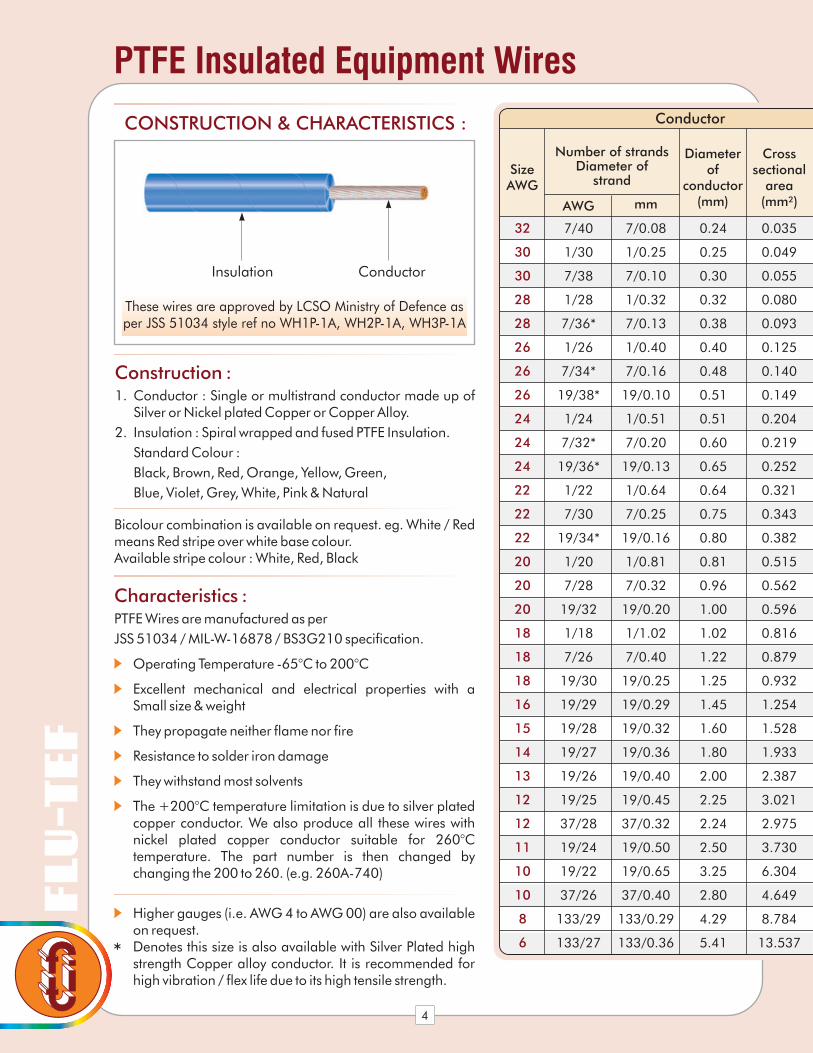
Characteristics :PTFE Wires are manufactured as per
JSS 51034 / MIL-W-16878 / BS3G210 specification.
Operating Temperature -65°C to 200°C
Excellent mechanical and electrical properties with a Small size & weight
They propagate neither flame nor fire
Resistance to solder iron damage
They withstand most solvents
The +200°C temperature limitation is due to silver plated copper conductor. We also produce all these wires with nickel plated copper conductor suitable for 260°C temperature. The part number is then changed by changing the 200 to 260. (e.g. 260A-740)
Higher gauges (i.e. AWG 4 to AWG 00) are also available on request.Denotes this size is also available with Silver Plated high strength Copper alloy conductor. It is recommended for high vibration / flex life due to its high tensile strength.
32
30
30
28
28
26
26
26
24
24
24
22
22
22
20
20
20
18
18
18
16
15
14
13
12
12
11
10
10
8
6
7/40
1/30
7/38
1/28
7/36*
1/26
7/34*
19/38*
1/24
7/32*
19/36*
1/22
7/30
19/34*
1/20
7/28
19/32
1/18
7/26
19/30
19/29
19/28
19/27
19/26
19/25
37/28
19/24
19/22
37/26
133/29
133/27
7/0.08
1/0.25
7/0.10
1/0.32
7/0.13
1/0.40
7/0.16
19/0.10
1/0.51
7/0.20
19/0.13
1/0.64
7/0.25
19/0.16
1/0.81
7/0.32
19/0.20
1/1.02
7/0.40
19/0.25
19/0.29
19/0.32
19/0.36
19/0.40
19/0.45
37/0.32
19/0.50
19/0.65
37/0.40
133/0.29
133/0.36
0.24
0.25
0.30
0.32
0.38
0.40
0.48
0.51
0.51
0.60
0.65
0.64
0.75
0.80
0.81
0.96
1.00
1.02
1.22
1.25
1.45
1.60
1.80
2.00
2.25
2.24
2.50
3.25
2.80
4.29
5.41
0.035
0.049
0.055
0.080
0.093
0.125
0.140
0.149
0.204
0.219
0.252
0.321
0.343
0.382
0.515
0.562
0.596
0.816
0.879
0.932
1.254
1.528
1.933
2.387
3.021
2.975
3.730
6.304
4.649
8.784
13.537
SizeAWG
Conductor
Number of strandsDiameter of
strand
Diameterof
conductor(mm)
Crosssectional
area(mm²)AWG mm
PTFE Insulated Equipment Wires
These wires are approved by LCSO Ministry of Defence asper JSS 51034 style ref no WH1P-1A, WH2P-1A, WH3P-1A
Insulation Conductor
CONSTRUCTION & CHARACTERISTICS :
Construction :1. Conductor : Single or multistrand conductor made up of
Silver or Nickel plated Copper or Copper Alloy.
2. Insulation : Spiral wrapped and fused PTFE Insulation.
Standard Colour :
Black, Brown, Red, Orange, Yellow, Green,
Blue, Violet, Grey, White, Pink & Natural
Bicolour combination is available on request. eg. White / Red means Red stripe over white base colour.Available stripe colour : White, Red, Black
4

PTFE Insulated Equipment Wires
Note : Current shown above are for single wire in free air at a temperature rise of approximately 50°C above ambient.
For more details refer graph given on page no. 11
5
Part No. Part No. Part No.
Dia. Overinsulation
Dia. Overinsulation
Dia. Overinsulation
Min.(mm)
Min.(mm)
Min.(mm)
Max.(mm)
Max.(mm)
Max.(mm)
Weightg/mMax.
Weightg/mMax.
Weightg/mMax.
Max.resistance
ofconductor.ohms/kmat20°C
CurrentRating(amp)
Finished Wire
Volt. Rating -250Vac (Type ET) Volt. Rating -600Vac (Type E) Volt. Rating -1000Vac (Type EE)
200A-740 200B-740 200C-7400.50 0.66 0.910.60 0.86 1.110.805 1.450 2.286 570.90 0.7
200A-130 200B-130 200C-1300.50 0.66 0.910.60 0.86 1.110.906 1.551 356.40 1.02.387
200A-738 200B-738 200C-7380.55 0.71 0.960.66 0.91 1.161.087 1.753 332.30 1.02.631
200A-128 200B-128 200C-1280.58 0.73 0.990.68 0.93 1.191.327 2.010 224.40 2.12.945
200A-736 200B-736 200C-7360.63 0.78 1.040.73 0.99 1.241.450 2.209 210.50 2.13.155
200A-126 200B-126 200C-1260.66 0.81 1.060.76 1.01 1.271.850 2.601 140.09 3.03.607
200A-734 200B-734 200C-7340.73 0.88 1.140.83 1.09 1.342.031 2.878 133.70 3.03.909
200A-1938 200B-1938 200C-19380.73 0.88 1.140.83 1.09 1.342.115 2.962 126.70 3.03.993
200A-124 200B-124 200C-1240.76 0.91 1.160.86 1.11 1.372.641 3.477 88.40 4.04.572
200A-732 200B-732 200C-7320.86 1.01 1.270.96 1.21 1.472.955 3.876 83.20 4.05.059
200A-1936 200B-1936 200C-19360.86 1.01 1.270.96 1.21 1.473.016 3.945 80.20 4.05.119
200A-122 200B-122 200C-1220.88 1.04 1.291.01 1.27 1.523.908 4.914 56.10 7.36.098
200A-730 200B-730 200C-7301.01 1.16 1.421.11 1.37 1.624.274 5.369 52.50 7.36.637
200A-1934 200B-1934 200C-19341.01 1.16 1.421.11 1.37 1.624.378 5.472 49.80 7.36.741
200A-120 200B-120 200C-1201.06 1.21 1.471.16 1.42 1.675.797 6.935 34.70 11.08.246
200A-728 200B-728 200C-7281.21 1.37 1.621.32 1.57 1.826.372 7.598 33.00 11.09.037
200A-1932 200B-1932 200C-19321.21 1.37 1.621.32 1.57 1.826.682 7.908 30.30 11.09.347
200B-118 200C-1181.42 1.681.68 1.9310.20 21.80 11.011.45
200B-726 200C-7261.63 1.871.87 2.1311.41 20.70 16.013.17
200B-1930 200C-19301.63 1.871.87 2.1311.79 19.10 16.013.55
200B-1929 200C-19291.85 2.102.20 2.4115.61 14.90 22.017.25
200B-1928 200C-19281.98 2.262.28 2.5418.08 12.09 26.020.21
200B-1927 200C-19272.23 2.482.59 2.8923.03 9.50 32.025.71
200B-1926 200C-19262.43 2.662.74 3.0227.65 7.59 35.030.39
200B-1925 200C-19252.71 2.973.07 3.3734.47 6.00 41.037.75
200B-3728 200C-37282.66 2.923.02 3.3233.30 6.30 41.036.53
200B-1924 200C-19242.99 3.203.30 3.5842.61 4.72 45.045.88
200B-1922 200C-19223.73 3.964.03 4.3469.05 2.99 55.073.48
200B-3726 200C-37263.22 3.473.58 3.8848.32 3.90 50.052.12
200C-13329 5.05 5.56 2.20 75.097.97
200C-13327 6.42 6.93 1.40 100.0153.30

PTFE Multicore Cable
2 - 5 0.8
0.7
0.5
8 - 15
16 - 30
No. of Cores Derating Factors (x Amps)
4
3
2
1
These cables are approved by LCSO,Ministry of Defence as per JSS 51038
Construction :1. Conductor
2. Core insulation : Spiral wrapped & fused PTFE tape
3. Braided shied
4. Jacket : PTFE tape wrapped & fused
Full range of Colour is available
The part number system are as mentioned below. The part number specify the size, number of cores / pairs and type of Shield and Jacket.
PTFE Mu l t i co re cab les f o r instrumentation and control applications are manufactured as per MIL-DTL-27500H / JSS 51038 specification to meet specific customer requirements.
The primary wire are PTFE insulated meeting requirements of JSS 51034 / MIL-W-16878. The cable possess all the unique electrical and mechanical properties of PTFE and are available in size from single wire screened or / and jacketed up to cable with a maximum of 66 pairs twisted and / or screened and / or jacketed as required.
Derating factor : The following table used as a guideline for derating factor in multicore cables.
Jacket Style
Shield Style
AWG Conductor likeWire Type
Core/Pair Like
No. of Core / PairC for Cable
- 00 - No Jacket06 - Taped PTFE
- U - No ShieldS - Silver Plated CopperN - Nickel Plated CopperT - Tin Plated Copper
- 732, 13329- AA - 250V SPC
AB - 600V SPCAC - 1000V SPCBA - 250V NPCBB - 600V NPCBC - 1000V NPCP - PairC - Core
C X XXX XX XXXXXXXPartNumberingSystem :
Jacket of PTFE
Silver Plated Copper round shield
Size of Conductor 7/32
600V SPC
2 Core
Cable
C S2C AB 06732Example :C2CAB 732 S06 :
6
Note : Jacket with PVC / FRLS PVC / Halogen free compound is also available.

RF Co-Axial Cable (Semi-Rigid)
F402
F402 T
F405
F405 T
50±1
50±1
50±1.5
50±1.5
98.1
98.1
105
105
1900
1900
1500
1500
230
20.6
230
20.6
427
15
427
15
70
70
20
20
148
22.2
148
22.2
262
20
262
20
120
120
35
35
69
24.6
69
24.6
123
25.5
123
25.5
250
250
74
74
39
28.5
39
28.5
72
27.5
72
27.5
450
450
130
130
26
---
26
---
40
---
40
---
600
600
180
180
20
20
20
20
13
---
13
---
---
---
---
---
---
---
---
---
Flu-TefPartNo.
Imped-anceOhms
Capa-citan-
ce
pf/MtrMax
Opera-ting
Frequ-encyGHZMax
Work-ing
Voltage
VoltsRMS
AttenuationdB/100 Mtrs, Maximum
Structural Return LossdB Minimum
at GHZ
Power ratingWatts, Maximum
at GHZ
0.1 0.10.4 0.41.0 1.03.0 3.010 1020 20
F402 M17 / RG402
M17 / 00001
M17 / RG405
M17 / 00001
0.92±0.018
0.92±0.018
0.51±0.013
0.51±0.013
Bare Copper
Tin Plated Copper
Bare Copper
Tin Plated Copper
51.18
52.23
22.76
23.51
1x0.92 SCCS
1x0.92 SCCS
1x0.51 SCCS
1x0.51 SCCS
2.97±0.025
2.97±0.025
1.68±0.05
1.68±0.05
3.58±0.025
3.58±0.025
2.20±0.025
2.20±0.025
F402 T
F405
F405 T
Flu-TefPartNo.
ReferenceMIL
Part No.
InnerConductor
n x mm
ConductorDiamm
DielectricCore Dia.
mm
OuterConductor
Copper Tubing
Over allDiamm
WeightKg/KmMax.
3
2
1
These cables areapproved by
LCSO/CEMILACMinistry of Defence
Construction :1. Solid conductor made up
of Silver plated copper clad steel (SCCS)
2. Dielectric of PTFE
3. Outer conductor made up of Deoxidized & annealed Electrolytic Bare or tin plated copper tubing
Operating Temperature :
-40°C to +125°C
These cables are designed for Super H igh Frequency connection upto 20GHz.
7
SEMI-RIGID Co-axial cables are manufactured as per JSS 51100/MIL-C-17G Specification.Characteristics :
100% screening, hence excellent protection against interference.
Ease of stripping, connecting and soldering.
Recommended minimum bending radius = 3 times the diameter of the cable.
No outgassing in vaccumApplications :
Use with wave-guides.
Micro-wave transmission & delay lines
High speed calculating machines
Low noise amplifier circuits
Perfectly screened connections
Improvement of technology of internal module connections
High stress resistance (vibrations)
Good Phase stability
Aerospace applications

RF Co-Axial Cable
1
2
3
4a 4b
These cables are approved byLCSO/CEMILAC
Ministry of Defence
Construction :1. Solid or standard conductor
made up of Silver plated copper clad steel (SCCS) or
Silver plated copper (SPC)
2. Dielectric layer of spiral wrapped & fused PTFE Tape
3. Outer conductor made up of
Single or Double braid of silver plated copper
4. An overall jacket of :
a. Jacket of wrapped & sintered PTFE Tape
b. One or two wraps of PTFE Tape. One or more glass fibre braids and coated with special high temperature varnish.
RF Co-axial cables are manufactured as per JSS 5 1 1 0 0 / M I L - C - 1 7 G Specification.
These cables are designed for low loss, stable operation from the relatively low frequencies through the higher frequencies in the microwave and radar regions of the frequency spectrum. Cables may also be used as circuit elements, delay lines or Impedance matching devices.
Operating Temperature-55°C to +200°C
They Wi ths tand mos t Solvents
F196
F188
F141
F400S
F142
F400
F393
F107
F187
F144
F302
F195
M17/RG178
M17/RG316
M17/RG303
M17/RG58
M17/RG142
M17/RG400
M17/RG393
URM107
M17/RG179
M17/RG144
M17/RG302
M17/RG180
7x0.1 SCCS
7x0.17 SCCS
1x0.94 SCCS
19x0.2 SPC
1x0.94 SCCS
19x0.2 SPC
7x0.79 SPC
7x0.82 SPC
7x0.1 SCCS
7x0.44 SCCS
1x0.64 SCCS
7x0.1 SCCS
0.3±0.025
0.51±0.025
0.94±0.025
0.98±0.025
0.94±0.025
0.98±0.025
2.39±0.025
2.46±0.05
0.3±0.025
1.33±0.025
0.64±0.018
0.3±0.025
---
---
---
---
0.13
0.13
0.16
---
---
---
---
---
9.30
18.15
46.13
38.00
74.40
74.40
260.40
180.00
16.07
208.32
59.60
29.46
0.10
0.10
0.13
0.13
0.13
0.13
0.16
0.16
0.10
0.16
0.13
0.10
1.8±0.1
2.49±0.1
4.32±0.13
4.20±0.13
4.95±0.13
4.95±0.13
9.90±0.25
9.00±0.25
2.54±0.13
2FG
5.13±0.13
3.58±0.1
0.84±0.05
1.52±0.076
2.95±0.13
2.95±0.13
2.95±0.13
2.95±0.13
7.24±0.13
7.25±0.15
1.6±0.076
7.24±0.13
3.70±0.13
2.59±0.076
Flu-TefPartNo.
ReferenceMIL
Part No.
InnerConductor
n x mm
ConductorDiamm
DielectricCore Dia.
mm
OuterConductorSPC ScreenStrand Dia
mm
Over allDiamm
WeightKg/KmMax.
Inner Outer
8

F196
F188
F141
F400 S
F142
F400
F393
F107
F187
F302
F144
F195
50±2
50±2
50±2
50±2
50±2
50±2
50±2
50±3
75±3
75±3
75±3
95±5
105
105
105
105
105
105
105
99.5
75
72
72
57
750
900
1400
1400
1400
1400
1875
5000
900
1700
3700
1100
---
---
---
---
---
---
---
---
---
---
---
---
---
---
---
---
---
---
---
---
---
---
---
250
256
110
---
---
---
---
---
---
---
---
---
17
16
16
---
---
140
140
140
140
350
---
---
---
---
---
308
190
92
135
115
125
59
48
141
85.3
59
---
14
17
21.3
21.3
17
17
20
20
41
80
350
350
350
350
880
545
110
350
880
135
170
125
49.2
66
62
56
28.5
23
82
42.6
23
---
19
21
24
24
22
22
23
23
78
160
650
650
650
650
1700
1000
200
650
1700
250
108
69
28.2
36
38
34
16.4
14
69
26.2
14.8
55.8
22
23
26
26
23.8
23.8
24
24
123
240
1100
1100
1100
1100
2800
1700
310
1100
2800
400
3
3
3
3
12.4
12.4
11
11
3
3
3
3
52.5
36
13
16
18
14.8
8.53
6.3
32
12.8
5.2
---
25
30
28
28
25.5
25.5
25
25
250
450
2400
2400
2400
2400
6300
3350
570
2400
6300
800
Flu-TefPartNo.
Impe-danceOhms
Capa-citan-
ce
pf/MtrMax
Opera-ting
Frequ-encyGHZMax
Work-ingVol-tageVoltsRMS
AttenuationdB/100 Mtrs, Maximum
Structural Return LossdB Minimum
at GHZ
Power ratingWatts, Maximum
at GHZ
0.1 0.10.4 0.41.0 1.03.0 3.010 1020 20
RG 58 C/U
RG 59 B/U
RG 174/U
RG 223
RG 213/U
RG 214/U
F400 S
F302
F188
F142
F107
F393
RG400
RG302
RG316
RG142
URM 107
RG393
50
75
50
50
50
50
Polyethylene Flu-Tef Reference Impedance RG Type
Conversion Chart for R. F. Co-Axial Cables from Polyethylene Dielectricto PTFE Dielectric
We have the design capability to develop R.F. Co-Axial cables, Specific to customers' requirements. This capability is backed by test facilities as required by U. S. MIL Standard / Indian defence standards (JSS).
RF Co-Axial Cable
9

Twinax Databus Cable
Construction :1. A standard conductor of either
Silver plated copper (SPC) or
Silver plated copper alloy (SPHA)
2. A. dielectric layer of spiral wrapped & sintered PTFE Tape
3. PTFE filler
4. Wrap of Pre sintered PTFE Tape
5. Screen 1 Braid of either
Silver plated copper (SPC) or
Silver plated copper alloy (SPHA)
6. Screen 2 Wrap of H igh permeability tape (HPT)
7. Screen 3 braid of
Silver palted copper (SPC)
8. Jacket of either
PTFE Tape wrapped & Sintered
OR
®Polyimide (Kapton ) tape +
PTFE Tape wrapped & Sintered
8
7
6
5
4
3
2
1
These cables areapproved by
CEMILACMinistry of Defence
These Radio Frequency, Twin axial known as Data bus cable for application in Electronic Equipment and Systems. The cable is primarily intended for interconnection of various equipment / sub systems used in Digital command / ResponseTime Division Multiplexing techniques on Aircraft . The requirements for Data bus cable specified herein comply with the requirements of US Mili tary Standard.
MIL-STD-1553B : Digital Time Division Command / Response Multiplex Data Bus.
Shielding Effectiveness : The shield s h a l l b e s e l e c t e d w i t h electromagnetic compatibility. Concerning the most commonly used types, the choice extends from single braids to complex shield configuration (braid, tape, braid) showing a very low transfer Impedance.
Temperature rating : -55°C to +200°CVoltage rating : 600 Vrms
W10614T
W10614T
F2709
F2709
F10612T
F10612T
24
24
24
19 x 0.12
7 x 0.20
19 x 0.12
1.08 ±0.05
77 ± 5 70 4.0 at 1Mhz 0.2 at 30 Mhz
1.20 ±0.05
77 ± 5 70 2.2 at 1Mhz 0.2 at 30 Mhz
1.08 ±0.05
77 ± 5 70 4.0 at 1Mhz 100 at 30 Mhz
PTFE
---
PTFE
PTFETape
---
---
0.10SPC
0.10SPC
®Kapton/PTFE
0.10SPHA
HPT
HPT
---
PTFE
PTFE
4.2
3.8
3.4
42
38
27
0.10SPC
0.10SPC
---
Flu-TefType No.
Flu-TefType No.
SizeAWG
ConductorStrandingn x mm
CoreDiameter
mm
ImpedanceOhms
CapacitanceMutual
pF/m Max.
AttenuationdB / 100m
Max.
Surface transferimpedance
Milliohms/mtr Max.
FillerBinderTape
Weightg/mMax.
1mm
2mm
2mm
Diamm
Nature
Screen Jacket
Physical Characteristics
Electrical Characteristics
10

Sleeving with inner diameter and wall thickness, not in standard range will be supplied on request.
PTFE Electrical Sleeving
PART NUMBER
W SED 01 0.50 0.25 1.31
1.55
2.70
4.30
5.50
6.88
11.50
13.22
15.65
19.20
24.30
28.00
32.40
36.50
0.25
0.30
0.40
0.40
0.40
0.40
0.50
0.50
0.50
0.50
0.50
0.50
0.50
0.75
1.00
1.50
2.00
2.50
3.00
3.50
4.00
5.00
6.00
7.00
8.00
9.00
W SED 02
W SED 03
W SED 04
W SED 05
W SED 06
W SED 07
W SED 08
W SED 09
W SED 10
W SED 11
W SED 12
W SED 13
W SED 14
INNER DIAMETER(D)
Nominal(mm)
WALL THICKNESS(T)
Nominal(mm)
APPROXIMATEWEIGHT
(gms/mtr)
PTFE Electrical Sleeving mee t s the per fo rmance requirements of JSS 54802/BS 2848 Type 6 specification.
Operating Temperature from -65°C to +250°C
Resistant to attack by lubr ican ts , Hydrau l i c , aircraft or rocket fuel, atmospheric conditions and virtually all chemicals.
D
T
These sleeves areapproved by LCSO
Ministry of Defence asper JSS 54802
Construction :
Sleeving is available in the following Colours :
Sleeving shall be manufactured from PTFE tape spiral wrapped and fused process.
Black, Brown, Red, Orange, Yellow, Green, Blue, Violet, Grey, White, Pink & Natural.
11
300
200
100
90
80
70
60
50
40
30
4 5 6 7 8 9 10 20CURRENT AMPERES
TE
MP
ER
AT
UR
E D
IFF
ER
EN
CE
(WIR
E R
AT
ING
MIN
US
TH
E A
MB
IEN
T - T
IN C
)
30 40 50 20 70 80 90100
WIRE SIZE 26 24 22 20 18 16 14 12 10300
200
100
90
80
70
60
50
40
30
200 300 400 500 600 700 800900
1000CURRENT AMPERES
TE
MP
ER
AT
UR
E D
IFF
ER
EN
CE
(WIR
E R
AT
ING
MIN
US
TH
E A
MB
IEN
T - T
IN C
)
6 4 2 1 1/0 2/0 3/0WIRE SIZE 8 4/0
Current Rating
