the city 2 slide™ assembly & installation instructions
TRANSCRIPT

Rev. 6/16 (SBK-CITY2 INSTL)
INTER-FAB, INC. 3050 S. ALVERNON WAY • TUCSON, AZ 85713520.790.7040 • 800.737.5386 • FAX 520.790.7127 • inter - fab .com
T H E C I T Y 2 S L I D E™
Assembly & Installation Instructions
IMPORTANTThese
instructionsmust remain
with theslide owner!
Visit inter-fab.com to view our installation help video. (Video does NOT replace installation instructions.)
IMPORTANT INSTALLATION INFORMATIONThe installation of this product should be done only by a licensed and professional installer. Installation shouldbe done strictly in conformance with all local building codes, electrical codes and other building and safety lawsand regulations. Among other things, that your installer should carefully analyze the need to bond the productto prevent an electrical hazard. Failure to properly install this product could result in a dangerous condition,including but not limited to electrical or structural hazards. Inter-Fab, Inc. disclaims all liability arising from theinstallation and the user assumes all risk associated with the installation.
WARNING

I N S TA L L AT I ON MANUA L C I T Y 2 S L I D E™
1Rev. 6/16 (SBK-CITY2 INSTL)
TABLE OF CONTENTS:
Intended Use Instructions ........................................................2
Water Safety Envelope.............................................................3
Slide Footprint Diagrams..........................................................4
Slide Position Diagrams ...........................................................5
Step 1 ..................................................................................6
Step 2 ..................................................................................7
Step 3 ..................................................................................7
Step 4 (A)..............................................................................8
Step 4 (B) .............................................................................8
Step 5 ..................................................................................9
Inspection Check List.............................................................10
Slide Care & Maintenance......................................................10
Paver Kit Information........................................................11-12
Exploded View of City 2 Slide ..................................................13
Parts List (corresponds with exploded view)..............................14
Hardware Parts List..............................................................15
Pages for Notes ..............................................................16-17
Inter-Fab Limited Warranty.....................................................18
I N S TA L L AT I ON MANUA L C I T Y 2 S L I D E™
2Rev. 6/16 (SBK-CITY2 INSTL)
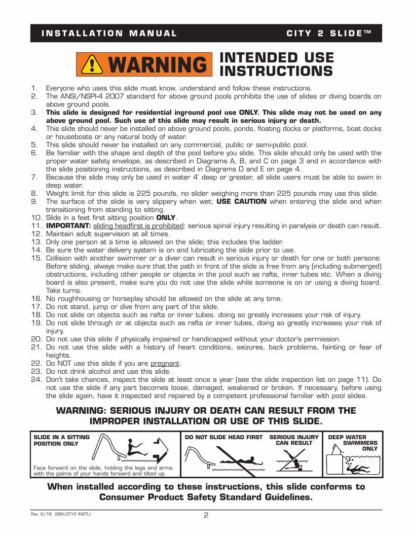
1. Everyone who uses this slide must know, understand and follow these instructions.2. The ANSI/NSPI-4 2007 standard for above ground pools prohibits the use of slides or diving boards on
above ground pools.3. This slide is designed for residential inground pool use ONLY. This slide may not be used on any
above ground pool. Such use of this slide may result in serious injury or death.4. This slide should never be installed on above ground pools, ponds, floating docks or platforms, boat docks
or houseboats or any natural body of water.5. This slide should never be installed on any commercial, public or semi-public pool.6. Be familiar with the shape and depth of the pool before you slide. This slide should only be used with the
proper water safety envelope, as described in Diagrams A, B, and C on page 3 and in accordance withthe slide positioning instructions, as described in Diagrams D and E on page 4.
7. Because the slide may only be used in water 4’ deep or greater, all slide users must be able to swim indeep water.
8. Weight limit for this slide is 225 pounds, no slider weighing more than 225 pounds may use this slide.9. The surface of the slide is very slippery when wet; USE CAUTION when entering the slide and when
transitioning from standing to sitting.10. Slide in a feet first sitting position ONLY.11. IMPORTANT: sliding headfirst is prohibited: serious spinal injury resulting in paralysis or death can result.12. Maintain adult supervision at all times.13. Only one person at a time is allowed on the slide; this includes the ladder.14. Be sure the water delivery system is on and lubricating the slide prior to use.15. Collision with another swimmer or a diver can result in serious injury or death for one or both persons:
Before sliding, always make sure that the path in front of the slide is free from any (including submerged)obstructions, including other people or objects in the pool such as rafts, inner tubes etc. When a divingboard is also present, make sure you do not use the slide while someone is on or using a diving board.Take turns.
16. No roughhousing or horseplay should be allowed on the slide at any time.17. Do not stand, jump or dive from any part of the slide.18. Do not slide on objects such as rafts or inner tubes. doing so greatly increases your risk of injury.19. Do not slide through or at objects such as rafts or inner tubes, doing so greatly increases your risk of
injury.20. Do not use this slide if physically impaired or handicapped without your doctor’s permission.21. Do not use this slide with a history of heart conditions, seizures, back problems, fainting or fear of
heights.22. Do NOT use this slide if you are pregnant.23. Do not drink alcohol and use this slide.24. Don’t take chances, inspect the slide at least once a year (see the slide inspection list on page 11). Do
not use the slide if any part becomes loose, damaged, weakened or broken. If necessary, before usingthe slide again, have it inspected and repaired by a competent professional familiar with pool slides.
SLIDE IN A SITTINGPOSITION ONLY
Face forward on the slide, holding the legs and armswith the palms of your hands forward and tilted up.
WARNING: SERIOUS INJURY OR DEATH CAN RESULT FROM THE IMPROPER INSTALLATION OR USE OF THIS SLIDE.
When installed according to these instructions, this slide conforms toConsumer Product Safety Standard Guidelines.
DO NOT SLIDE HEAD FIRST SERIOUS INJURYCAN RESULT
DEEP WATER SWIMMERS
ONLY
INTENDED USEINSTRUCTIONSWARNING

I N S TA L L AT I ON MANUA L C I T Y 2 S L I D E™
3Rev. 6/16 (SBK-CITY2 INSTL)
DIAGRAM A(NOT TO SCALE)
DIAGRAM C(NOT TO SCALE)
Minimum Water Safety Envelope
4'6"
3'
4'
3'
4'6"9'
4'Point A
4'
WATER SAFETY ENVELOPE:A minimum water depth of three feet (3') under the exitof the slide which increases to a depth of four feet (4')at point A which is located four feet six inches (4'6")from the back wall of the pool. A minimum depth offour feet (4') must be maintained at a distance of ninefeet (9') along the centerline of the slide from point A.The above described water depth profile shall extend aminimum of three feet three inches (3'3") on eitherside of the centerline of the slide. (See Diagrams A, B & C)
13'6"
6'6"
13'6"
20" Max
CENTER
WATER SAFETYENVELOPE
15˚20" Max
Level DeckWater Level
DIAGRAM B(NOT TO SCALE)Minimum SlideClearance Area
13'6"
2'6"
C/L
6'6"
3'3"3'3"

I N S TA L L AT I ON MANUA L C I T Y 2 S L I D E™
4Rev. 6/16 (SBK-CITY2 INSTL)
SLIDE FOOTPRINT DIAGRAMSDIAGRAM D – RIGHT TURN SLIDE
DIAGRAM E – LEFT TURN SLIDE
NOTE: FINAL POSITION MUST ENSURE THAT ALL WATER FALLING OFF SLIDE LANDS IN POOL. DIMENSIONSMAY VARY FROM SLIDE TO SLIDE. IT IS RECOMMENDED THAT THE FULLY ASSEMBLED SLIDE BE USED ASA TEMPLATE FOR INSTALLATION.
RECOMMENDED MIN. DECK AREA:
12’ x 5’

I N S TA L L AT I ON MANUA L C I T Y 2 S L I D E™
5Rev. 6/16 (SBK-CITY2 INSTL)
SLIDE & WATER STUB-UP PLACEMENT DIAGRAMSDIAGRAM F - City 2 Slide - Left Turn(NOT TO SCALE)
DIAGRAM G - City 2 Slide - Right Turn(NOT TO SCALE)
3” MINIMUMOVERHANG
3” MINIMUMOVERHANG

I N S TA L L AT I ON MANUA L C I T Y 2 S L I D E™
6Rev. 6/16 (SBK-CITY2 INSTL)
STEP ONE:FLUME ASSEMBLY
Open box and remove slide components andparts pack.
Flatten box and use it as a protective surfaceto avoid scratching the acrylic parts.
Turn flume sections upside down, check flumegasket integrity. (Diagram H)
Align bolt holes on the flanges.
Use vice grips to hold halves together.(Diagram I)
Use a small dab of anti seize lubricant(included) on the bolt threads.
Insert bolts – hardware kit CS-102-SS, flume toflume. (Diagram J)
NOTE: (Hardware Order: bolts/washers, slideflange/slide flange, washers/nuts.) Check flumeat inside seam for even fit.
HAND TIGHTEN ONLY.
DIAGRAM H
DIAGRAM I
DIAGRAM J

I N S TA L L AT I ON MANUA L C I T Y 2 S L I D E™
7Rev. 6/16 (SBK-CITY2 INSTL)
STEP TWO:Handrail Pre-Assembly Procedure1. Pre-assembled wedge, round to flat con-
nector and carriage bolt as shown inDiagram K above.
2. Insert the assembly from step 1 aboveinto the handrail as shown in the Diagramabove by sliding a round to flat connectorinto the handrail opening until the Shoulderportion of the connector seats against theend of the tubing. The Connector mayhave to be tapped into place.
3. With one hand hold the connector tightinside the handrail while pulling the carriagebolt away from the handrail locking thewedge into the connector.
4. Remove the carriage bolt.5. Repeat steps 1 through 4 on each end of
both handrails.
DIAGRAM K (NOT TO SCALE) DIAGRAM L (NOT TO SCALE)
STEP 2Insert assembly into handrails as shown, until shoulderportion of connector seats against end of tubing, tapconnector into place if needed.
STEP 1Pre-assemble wedge, round-to-flat connector andcarriage bolt as shown.
STEP 3Hold connector tight inside handrail, then pull bolt awayfrom handrail to lock wedge into anchor.
STEP 4Remove carriage bolt and repeat steps 1-3 for eachend of both handrails.
STEP THREE:Slide Assembly Procedure1. Slip the two short legs over the 2 aluminum projections
on the underside of the Lower Flume. NOTE: The shorterof the two legs will go on the projection on the inside ofthe flume curve.
2. Using two people and while holding the two legs in place,turn the slide over.
3. One person must now hold the slide at its normal heightwhile the second person installs the two long legs andinserts the ladder (squared end) snugly into the matingslots on the underside of the Upper Flume. See DiagramL above.
4. Insert a handrail into the 1-1/16" (2.56 cm) diameterhole on the top of the slide runway, at the same timeensure the predrilled holes in both the handrail and ladderare aligned. See Diagram L above. Install one 7-1/2" (19 cm)aluminum spacer between the top set of predrilled holesand secure with a 1/4" x 12" (.64 x 30.5 cm) bolt, flatwasher, lock washer, and 1/4" (.64 cm) nut. Repeat thisprocess for the second set of holes from the top utilizingthe 5-1/2" spacer and secure with 1/4" x 7-1/2" (.64x 19 cm) bolt. Secure the bottom of the handrail with a1/4" x 1-1/2" (.64 x 3.8 cm) hex head bolt.
5. Repeat 1 through 3 for the other handrail.6. Align flume sections and tighten flume bolts that were
“hand tightened” only in step one. Place protective capson bolt heads and nuts.
INSTALLATION MUST MEET ALL NATIONAL & LOCAL BUILDING CODES

I N S TA L L AT I ON MANUA L C I T Y 2 S L I D E™
8Rev. 6/16 (SBK-CITY2 INSTL)
DIAGRAM M DIAGRAM N DIAGRAM O
ELECTRICAL BONDING: Electrical bonding is required and slide must be installed in accordance with your local code. Bondeach tubular leg by placing a bonding wire between the leg and the bonding washer and secure with a self tapping screw.See Diagram M above. Bond the handrails by placing the bonding wire under the lowest washer & nut on each side of theladder and run the bonding wires down the inside of each ladder leg.
STEP FOUR (A):INSTALLING SLIDE PRIOR TO POURING DECK
Position the slide relative to the pool wall per the slideplacement instructions shown in Diagrams D and E, ensuringthat the minimum water safety envelope is maintained asshown in Diagrams A, B & C. Position slide so that the legsand ladder bottoms will be 4" (10 cm) below the finishedgrade.
Utilizing a 1/2" diameter drill enlarge the holes at the bottomof each slide leg and insert a 6” length of 3/8" diameterrebar through each hole.
Once the correct slide location has been determined installa 1/2" (stub-up) from the pool return. The stub-up shouldbe located near the inside right side ladder leg, at least 2”in front of ladder towards pool. Installing a 3 way valvebetween the stub-up and the slide plumbing is suggested.
Level top surface of the slide exit runway. Level the top ofthe slide in both directions. Level the ladder using a levelon any step. Ensure that the ladder is sloped 15 degreesfrom vertical (see Diagram C) then, should no verticaladjustment of the slide legs be required, drill a small pilothole, then screw one 14 X 1 self tapping screw througheach leg (approx. 1" below the top of the leg) into the legspud; otherwise, move the legs in relation to the spudsuntil proper leveling is obtained before inserting thescrews.
Secure the slide so it will not move while the deck is beingpoured. TIP: to allow for easy removal of concrete from theladder and legs apply a heavy coat of wax or wax paperapproximately 1 foot above the deck surface. Allow concreteto cure for 24 hours prior to using the slide.
STEP FOUR (B):INSTALLING SLIDE USING DECK FLANGES (SOLDSEPARATELY)
Position the slide relative to the pool wall per the slideplacement instructions shown in Diagrams D and E, ensuringthat the minimum water safety envelope is maintained asshown in Diagrams A, B & C.
Once the slide is properly positioned, place a deck anchorover each slide leg and using the 4 holes on each flange asa template drill four 1/2" diameter holes into the deck toa depth of 2 1/2". Insert the anchor into the hole until itis flush with the surface. Position the flange, insert the lagbolt and tighten. (see Diagram N & O above)
Ensure that the ladder is sloped 15 degrees from vertical(see Diagram C) then, using the 2 holes on each ladderfoot as a template drill 1/4" holes 2" (5 cm) deep. Drive 2anchor stud bolts into the ladder leg positions so that 1/2"(1.3 cm) of the studs project above the deck and unscrewthe nuts from the anchors. Place the slide so the legs dropinto the deck anchors and the ladder legs locate over thestud anchors, secure the ladder leg nuts onto the anchors.
Once the slide legs are within the deck flanges (ignoring theexisting holes in the slide legs) drill a 1/4" hole into theslide leg through the center of the large 3/8" hole in thedeck flange. Insert the aluminum bushing into the hole inthe flange until it hits the slide leg, now insert the bolt thruthe bushing about 1" into the slide leg. With the bolt inposition, drill a 1/4" hole into the slide leg thru the hole inthe opposite side of the flange. Push the bolt completelythru the slide leg, add washer and tighten nut.
Level top surface of the slide exit runway. Level the top ofthe slide in both directions. Level the ladder using a levelon any step. Should no vertical adjustment of the slide legsbe required, drill a small pilot hole, then screw one 14 x1 self tapping screw through each leg (approx. 1" belowthe top of the leg) into the leg spud; otherwise, move thelegs in relation to the spuds until proper leveling is obtainedbefore inserting the screws.
NOTE: YOU WILL CHOOSE TO EITHER FOLLOW STEPFOUR A OR B DEPENDING ON WHETHER THE SLIDEWILL BE AN IN-DECK OR ON-DECK INSTALLATION.INTER-FAB CANNOT/DOES NOT GUARANTEE THE
Small Hole (5/16”)
Lock NutWasher
Slide Leg
Slide Flange
Large Hole (3/8”)
1/4” Through BoltWasher
Aluminum Bushing

I N S TA L L AT I ON MANUA L C I T Y 2 S L I D E™
9Rev. 6/16 (SBK-CITY2 INSTL)
STEP FIVE:CONNECTING THE WATER SUPPLY
Feed the 1/2” diameter flex hose (provided)through the slots on the right side of the slideladder. (Diagram P)
Use PVC primer and glue to attach the feedhose to the slide fitting. (Diagram Q)
Attach ball valve shut off near deck “stub up”.(Diagram R)
Attach hose to deck “stub up” last.
NOTE: Make sure that the water stub up is atleast 2” in front of the ladder (toward pool).
Water Supply Includes: 10’ of 1/2” flex PVCpipe, 1/2” on/off ball valve. For best results, useclear glue and primer for plumbing installation.
DIAGRAM P
DIAGRAM Q
DIAGRAM R

I N S TA L L AT I ON MANUA L C I T Y 2 S L I D E™
10Rev. 6/16 (SBK-CITY2 INSTL)
FINAL INSPECTION CHECK LIST:
1. INSPECT THE SLIDE FLUMES FOR ANY VISIBLE DAMAGE, CRACKS, OR TEARS.
2. INSPECT THE SLIDE FOR SHARP EDGES, CRACKS, TEARS OR PROTRUSIONS ON THELADDER, DECK FLANGES, HANDRAILS AND SLIDE FLUMES.
3. INSPECT THE SLIDE FOR ANY LOOSE OR CORRODED HARDWARE.
4. INSPECT ALL SLIDE LADDER TREADS AND STEP ATTACHMENT POINTS FOR ANY SIGNOF BENDING, FATIGUE, SHEARING OR YIELD. A SURFACE OR LADDER TREAD SHOWINGSIGNS OF YIELD IS INDICATED BY FINE CRACKING OR CRYSTALLIZATION.
5. INSPECT THE CONNECTION OF THE SLIDE HANDRAILS FOR SECURED FASTENING ANDRIGIDITY. PROPERLY ATTACHED HANDRAILS CANNOT BE PULLED AWAY FROM THEIRSOCKETS OR CONNECTION POINTS.
6. MEASURE THE DEPTH OF THE WATER IN FRONT OF THE SLIDE EXIT AND CONFIRMCOMPLIANCE WITH DIAGRAMS A, B & C.
7. CERTIFY THE PROPER POSITION OF THE SLIDE EXIT AS SHOWN IN DIAGRAMS D & E.
8. VERIFY THE SLIDE WARNING LABEL IS SECURELY ADHERED TO THE SLIDE.
9. GIVE THESE INSTALLATION INSTRUCTIONS TO THE CUSTOMER AND GO OVER THEINTENDED USE INSTRUCTIONS WITH THEM.
CITY 2 SLIDE™ CARE & MAINTENANCE:
Your slide requires periodic maintenance to keep it looking like new.
• Wash monthly or more frequently, if needed. Be careful to keep cleaning material fromentering the pool.
• Wash with mild soap, such as hand dishwashing soap, and avoid using strong cleanersor abraisives. Avoid strong alkaline (such as tri-sodium phosphate) or highly acidic cleaners.Avoid bleach and ammonia.
* These suggestions and data based on information believed to be reliable, from ourraw materials manufacturers. They are offered in good faith, but without guarantee,as conditions and methods of use and procedures are beyond our control.

I N S TA L L AT I ON MANUA L C I T Y 2 S L I D E™
11Rev. 6/16 (SBK-CITY2 INSTL)
Fig. 1
Minimum Concrete Pads – CITY 2™ Slide(Plan View – NOT to Scale)
Pool Edge
5 concrete pads are needed:(1) 12” wide x 32” long x 12” deep(4) 16” wide x 16” long x 12” deep
Center feet on pads
When installing an Inter-Fab City 2™ slide using a paver kit, you must ensure that all standardinstallation requirements are met. The slide must be compatible with the type of pool on the intendedinstallation and all ANSI/APSP/ICC-5 2011 requirements must be met. Refer to installation manual.
Figure 1 illustrates an example of the minimum concrete pads recommended for the City 2™ slide.Specific slide position and concrete pad orientations may vary. Make sure to allow for water stubup location near the ladder section of the City 2™ slide when pouring the concrete pad for the laddersection. In order to ensure proper placement, you will need to set the slide up first to determinewhere the concrete pillars will be located.
Figure 2 shows a side view illustration of the City 2™ slide foot deck anchor and wedge anchorsused in a paver installation. NOTE: 4 ea. CITY-DECK ANCHOR are also required (not includedwith slide or paver kit) to complete the City 2™ paver installation. Pavers can be a maximumof 3” thick. Pavers must be mechanically attached to the concrete pad using a setting material(such as mortar or thinset for example) that is no thicker than 3/8”.
1” of each 3/8” x 7” wedge anchor (18 ea.) needs to be exposed above the final deck surface.The 3/8” wedge anchors must be drilled to a depth of 6” with 1” of the bolt left remaining abovethe final deck surface. The 3/8” x 7” wedge anchors (16 ea.) replace the 5/16” lag bolts andlag shields (16 ea.) included with the required CITY-DECK ANCHOR parts (4 ea.), one set per leg.See Figure 3. The remaining 3/8” x 7” wedge anchors (2 ea.) are used (1 per side) to attach theladder bottom to the concrete pad and replace the 1/4” x 2-1/4” wedge anchors (4 ea.) fromhardware kit CS-101-SS.
The ladder bottom must have the forward 1/4” hole on each side (toward slide) drilled to 1/2” toaccommodate the 3/8” x 7” wedge anchor. The rear 1/4” holes on the ladder bottom are notused with the paver installation. See Figure 4. You will need to factor in the thickness of your paver(3” MAX.) and the thickness of your setting material (3/8” MAX.) for your individual installation.
You will need a 3/8” masonry bit and a 1/2” regular bit for the City 2™ slide.
Inter-Fab Inc. will not be responsible for damage to pavers caused by drilling or mechanicallyattaching to concrete pad. Refer to paver manufacturer’s specific installation instructionsbefore beginning.
Fig. 2
Example of Deck Anchor on Concrete Pad (Side View)
CONCRETE
12” min.
Layer of setting material tosecure pavers to concrete.
PAVERS3” max.
Drawing IsNOT To Scale
HEIGHT OF WEDGEANCHOR ABOVEFINAL DECK SURFACE
WEDGE ANCHORS
16” min.
5” min.from edge
DECK ANCHOR
PAVER KIT INFO – CITY 2 SLIDE

I N S TA L L AT I ON MANUA L C I T Y 2 S L I D E™
12Rev. 6/16 (SBK-CITY2 INSTL)
Fig. 3
When installing a City 2™ slide using a paver kit, disregard the lag shield instructions that areincluded with the CITY-DECK ANCHOR. See Figure 5.
Fig. 4
Fig. 5
You will need a 3/8” masonry bit and a 1/2” regular bit for the City 2™ slide.
Inter-Fab Inc. will not be responsible for damage to pavers caused by drilling or mechanicallyattaching to concrete pad. Refer to paver manufacturer’s specific installation instructionsbefore beginning.
PAVER KIT INFO – CITY 2 SLIDE – CONTINUED
I N S TA L L AT I ON MANUA L C I T Y 2 S L I D E™
13Rev. 6/16 (SBK-CITY2 INSTL)
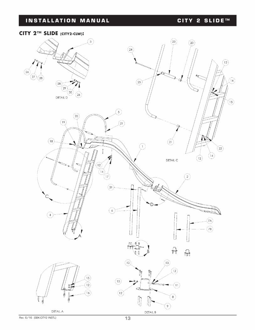
CITY 2™ SLIDE (CITY2-CLW):

I N S TA L L AT I ON MANUA L C I T Y 2 S L I D E™
14Rev. 6/16 (SBK-CITY2 INSTL)
CITY 2™ SLIDE (CITY2-CLW):
DRAWING REPRESENTS THE FOLLOWING PART NUMBERS: CITY2-CL (shown) CITY2-CR
ALL CHART INFORMATION BELOW CORRESPONDS WITH THE DRAWING ON THE PREVIOUS PAGE.<---
NOTES: City 2 Slides available in white, blue, tan and gray.City 2 Slides available in both right and left turns.
* City Slide Deck Anchors are Sold Separately (4 required for a complete City Slide install)
ITEM # COMPONENT DESCRIPTION CS
-101
-SS
CS-102
-SS
CITY2
-PRT
SPA
CK
CITY-DECK
ANCH
(4)
CITY
2
KITS – QTY. COUNTS
1 CITY2-URUN City 2 Upper Runway 1 2 CITY2-LRUN City 2 Lower Runway 1 3 H-C2 L GASKET or H-C2 R GASKET Gasket (either right turn or left turn gasket) 1 4 CITY-LADDER Aluminum Ladder Assembly 1 5 CITY HANDRAIL Aluminum Slide Handrails 2 6 H-45.500 LEG 45.50” Aluminum Slide Leg 2 7A H-23.250 LEG 23.25” Aluminum Slide Leg 1 7B H-20.500 LEG 20.50” Aluminum Slide Leg 1 8 CITY-DECK ANCH Deck Anchor (optional item; ordered separately) 1* 9 5/16” Concrete Insert Lag Shield 4* 10 5/16” x 2-1/2” Hex Lag Screw S.S. 4* 11 1/4” x 3” Hex Bolt S.S. 1* 12 1/4” Flat Washer S.S. 8 4* 13 1/4” x 3/8” Aluminum Bushing 1* 14 1/4” Lock Washer S.S. 8 15 1/4” Finish Nut S.S. 8 1* 16 1/4” x 2-1/4” Wedge Anchor S.S. w/Washer 4 17 1/4” x 2-1/4” Tap Bolt S.S. 2 . 18 1/4” x 12” Carriage Bolt 2 19 7-1/2” Aluminum Spacer 2 20 Round to Flat Nylon Connector 4 21 Round to Flat Nylon Connector w/Wedge 4 22 1/4” x 1-1/4” Machine Bolt S.S. 2 23 5-1/2” Aluminum Spacer 2 24 1/4” x 7-1/2” Carriage Bolt S.S. 2 25 Round to Round Nylon Connector 4 26 H-.562 X .390 CAP Gray Protective Cap 12 27 H-SS 3/8 X 1-3/4 3/8” x 1-3/4” Hex Head Bolt S.S. 6 28 H-SS 3/8 FLT WASHER 3/8” x 1” Flat Washer S.S. 12 29 H-SS 3/8 LOC WASHER 3/8” Lock Washer S.S. 6 30 H-SS 3/8 F NUT 3/8” Finish Nut S.S. 6 31 #14 x 3/4” S.S. Pan Head Screw 8 32 H-1/2 SPA HOSE 1/2” Spa Hose - 10 ft 1** 33 H-1/2 BALL VALVE 1/2” On/Off Ball Valve 1*** OPTIONAL - Deck Anchors are Sold Separately. Must order 1 for each slide leg for a total of 4.** not pictured
CS-101-SS: Handrails; Ladder to Deck; Leg to FlumeCS-102-SS: Flume to Flume
Check your local electrical coderequirements for bonding requirements.

I N S TA L L AT I ON MANUA L C I T Y 2 S L I D E™
15Rev. 6/16 (SBK-CITY2 INSTL)
PARTS LIST:
CS-101-SS – LEG AND HANDRAIL HARDWARE QTY COMPONENT DESCRIPTION 2 1/4” x 12” carriage bolt s.s. 2 1/4” x 7-1/2” carriage bolt s.s. 8 1/4” finish nut s.s. 8 1/4” lock washer s.s. 8 1/4” flat washer s.s. 8 #14 x 3/4” s.s. pan head screw 2 1/4” x 1-1/4” tap bolt s.s. 2 1/4” x 2-1/4” tap bolt s.s. 4 1/4” x 2-1/4” wedge anchor s.s. 8 round to flat nylon connector 4 round to round nylon connector 4 nylon wedge connector 2 5-1/2” aluminum spacers 2 7-1/2” aluminum spacers
CS-102-SS – FLUME HARDWARE QTY PART NUMBER COMPONENT DESCRIPTION 6 H-SS 3/8 X 1-3/4 3/8” x 1-3/4” all-thread bolt s.s. 12 H-SS 3/8 FLT WASHER 3/8” x 1” flat washer s.s. 6 H-SS 3/8 LOC WASHER 3/8” lock washer s.s. 6 H-SS 3/8 F NUT 3/8” finish nut s.s. 12 H-.562 X .390 CAP gray protective cap 1 H-ANTI-SEIZE one packet of anti-seize bolt lubricant
CITY 2 HANDRAILS QTY PART NUMBER COMPONENT DESCRIPTION 2 CITY-HANDRAIL aluminum slide handrails
CITY 2 SLIDE LEGS QTY PART NUMBER COMPONENT DESCRIPTION 2 H-45.500 LEG 45.50” aluminum slide leg 1 H-23.250 LEG 23.25” aluminum slide leg 1 H-20.500 LEG 20.50” aluminum slide leg
CITY 2 LADDER QTY PART NUMBER COMPONENT DESCRIPTION 1 CITY-LADDER aluminum ladder assembly
CITY 2 HOSE AND BALL VALVE QTY PART NUMBER COMPONENT DESCRIPTION 1 H-1/2 SPA HOSE 1/2” spa hose - 10 ft. 1 H-1/2 BALL VALVE 1/2” on/off ball valve
CITY 2 ON DECK ANCHORS QTY PART NUMBER COMPONENT DESCRIPTION 1 CITY-DECK ANCH slide flange with concrete anchors for City 2

I N S TA L L AT I ON MANUA L C I T Y 2 S L I D E™
16Rev. 6/16 (SBK-CITY2 INSTL)
NOTES:

I N S TA L L AT I ON MANUA L C I T Y 2 S L I D E™
17Rev. 6/16 (SBK-CITY2 INSTL)
NOTES:

I N T E R - F A B L IM I T E D WARRAN T Y
18Rev. 6/16 (SBK-CITY2 INSTL)
LIMITED WARRANTYInter-Fab, Inc. will repair or replace, at its option, any product manufactured by Inter-Fab, Inc. that fails duringthe applicable warranty period because of a manufacturing or material defect; provided that the defect is notthe result of improper installation, improper use or care, negligence, alterations or modifications to the product,or natural accidents (acts of God). The applicable warranty period for products manufactured by Inter-Fab, Inc.is three (3) years from the date of retail purchase, except as specified below:
Echoes of Nature™ products are individually handcrafted and painted by skilled artisans and as a result,dimensional differences and color variations are normal and are not a basis for warranty coverage. The warrantyperiod for pumps sold with the Echoes of Nature™ products is three (3) years from the date of retail purchase.
Pool Games equipment warranty periods are as follows: Volleyball Poles, Basketball Poles, Basketball Rim,and Basketball Backboard are one (1) year from date of retail purchase. Volleyball, Volleyball Net, Basketball,Basketball Net, and pumps are warranted for ninety (90) days from date of retail purchase.
The Board Fall, Board Fall-L (LED), and Board Fall-F (fiber optic) water features, used for the Jump & Splash™,T7™ and aquaBoard™ products, have a warranty period of one (1) year from the date of retail purchase.
Zoomerang™ slide products warranty period is one (1) year from the date of retail purchase.
Build Your Own Slide™ (BYOS™), Build Your Own Slide 2™ (BYOS 2™), Garden Ride Series™, Pool/SpaTable™, Pool Seat™, Tanning Ledge Table™ and Pool Lifestyle™ products warranty periods are one (1) yearfrom the date of retail purchase.
City 2™ Slide and City Base™ products warranty period are one (1) year from the date of retail purchase.
Unless expressly stated otherwise all products manufactured by Inter-Fab are for residential installation (singlefamily residence) inground pool use only. Inter-Fab, Inc. expressly disclaims any and all warranties and liabilityarising from the installation or use of its residential products for any non-residential use such as semi-public,public, or commercial applications. Products expressly manufactured for commercial installation and use willbe subject to this limited warranty.
This limited warranty is in lieu of all other warranties, whether express or implied. Inter-Fab, Inc. disclaimsany warranty of merchantability or fitness for a particular use, and noninfringement in relation to any of itsproducts and Inter-Fab, Inc. is not liable for consequential, incidental or specific damages. This warranty islimited to the repair or replacement of the manufacturing or material defect, or refund of the original purchaseprice, whichever is less, at the sole option of Inter-Fab, Inc., and expressly does not cover any labor or reinstallationexpenses related to the replacement of any and all Inter-Fab products. This limited warranty shall be the soleand exclusive remedy of irrespective of whether the claims are made in contract, tort, warranty, law, equityor by statue.
This warranty is to the original purchaser of the product only. Inter-Fab’s limited warranty is neither transferablenor portable from consumer to consumer. The effective coverage date begins at the date of retail purchase.Product owner or representative must notify Inter-Fab, Inc. (or its wholesale agent) in writing, giving a fulldescription of the nature of the product defect or failure along with proof of purchase, serial number(s) of theproduct and photos within thirty (30) days of the expiration of the applicable warranty period. Inter-Fab, Inc.reserves the right to physically inspect damaged or defective products or components to determine the causeof the damage or defect, prior to authorizing repair or replacement of its products.
3050 S. ALVERNON WAY • TUCSON, AZ 85713520.790.7040 • 800.737.5386 • FAX 520.790.7127 • INTER-FAB.COM