the certified fire wall - arcelormittalamsections.arcelormittal.com/.../articles/firebreak... ·...
TRANSCRIPT

The Certified Fire wall

• Insulate and keep a fire in ONLY ONE cell of a building
• Avoid the structure and the front fall towards the outside– Secure intervention of firefighters & emergency services
– Optimize rescues
• Meet the new insurance companies requirements
– 4h certified !
Why the Firestop wall?

Presentation Plan
• Section I: Firewall Firebreak 4h general presentation
• Section II: Firewall Firebreak 4h detailed presentation
• Section III: Firewall Firebreak 4h CSTB Certification Test
• Section IV: Firebreak system promotion & development
• Section V: Extra part on Fire regulation

Section I
Firewall Firebreak General Presentation

Firebreak 4h: Description
• Standard panels : – Length: 2,50 m – Height: 1,25 m– Thickness: 170 mm
• Smaller panels available (for adaptation to the wall dimensions)
• ALUZINC coating
• Less than 100 kg/m2
• Steel structure on each side

Internal Composition
• Symmetrically, successive coats of :– Cellular glass (Foamglas)– Plaster (Prégyfeu)– Core in Fibro-silicate
– + bonding (special glue)
Foamglas
Plaster
Fibro-silicate
Foamglas
Plaster
Steel sheetin ALUZINC
Steel sheetin ALUZINC
17 cm

• Light construction with a good stability
• Flexible (easy to dismantle, well adapted for the renovation)
• No foundations needed (pressure on the ground surface around 1kg/cm2 a height of 15 meters) => construction simplified, removable and reusable
• Delivery in standard panels ready for use
• Easy erection by a steel fabricator
• 4h ISO-fire resistance attested by the approved French laboratory of the CSTB, for a height of 15m with unlimited width
Main Advantages
Main Advantages
• The only one fire wall system in the market (4h, 15m) certified
• Collapse towards the side of the fire, therefore no risk for firefighting and rescue teams
• Good thermal insulation : Maximum temperature of 120 degrees on the outer face
• Good acoustic insulation => Rw (C t r) = 43 (-1, -3) dB
• Aluzinc Benefits : aesthetics (naturally silver), excellent resistance to corrosion, officially approved for food storage application (according to the standard NFA 36-712-6 April 2006) : No specific treatment or additional surface is to be added

Sustainable Advantages
• Free of fibers : Inside the wall, mineral, insulating and non combustible materials (M0)
• Guaranteed corrosion protection against perforation
• Dry system (doesn’t require water during construction phase)
• Doesn’t emit toxic substances (gases and fumes) during normal conditions and in case of fire
• Recyclable and environmentally inert materials

Sustainable Advantages
• Safe working conditions during erection (light elements)
• Fast, easy and cheap installation process
• Allows less disruptive refurbishment for existing buildings
• Possibility of re-use and relocate the wall
• Storage on pallets, less space needed, less trucks, less fuel consumption

Industry
Warehousingcompanies
Combustible Materials
Warehouses
Refurbishment / Rehabilitation
Refrigeratingindustry
Theatres / Concert halls
Food storage
Scope of applications
Maritime/Naval applications
Other possible applications :

Section II
Firewall Firebreak Detailed Presentation

• The wall is supported by a steel structure on each side
• The structure doesn’t bear the wall …but the FRAME !
• Fuse fixations : bimetallic strip joined with tin=> when the tin casts, the steel structure comes off and sags on the fire.
Mechanism
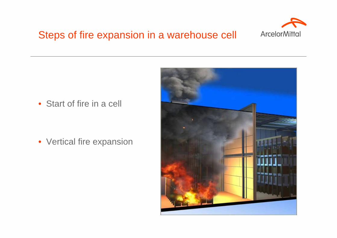
• Start of fire in a cell
• Vertical fire expansion
Steps of fire expansion in a warehouse cell

• Accumulation of warm gas under the roof
• Deformation of the frame
• Fusible connections ensure that the link between wall and heated structure disappears
Steps of fire expansion in a warehouse cell
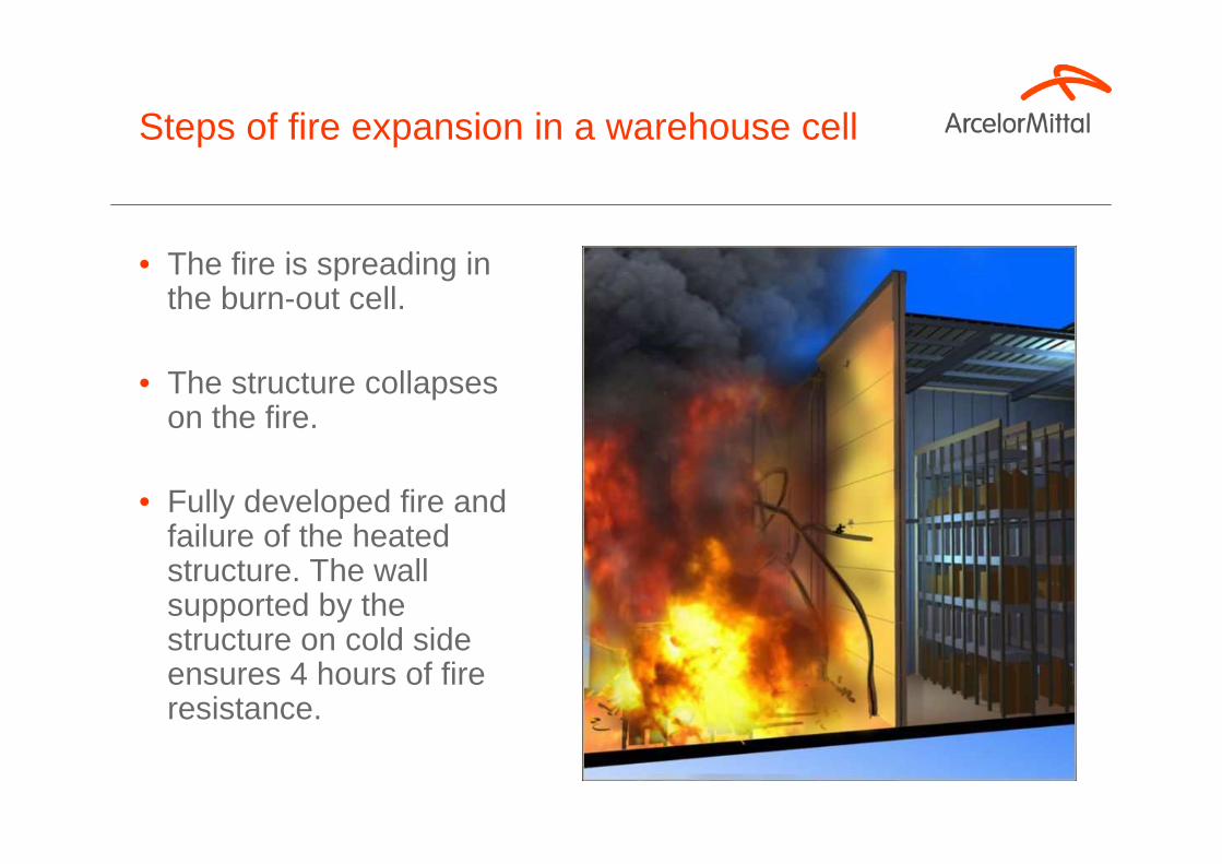
• The fire is spreading in the burn-out cell.
• The structure collapses on the fire.
• Fully developed fire and failure of the heated structure. The wall supported by the structure on cold side ensures 4 hours of fire resistance.
Steps of fire expansion in a warehouse cell

• Fire is decreasing / Decay phase of the fire
• Protected by Firebreak, the adjacent cell on the cold side is safe. It is not damaged.
Steps of fire expansion in a warehouse cell

Traditional endwall structures
Fuses on 5 m x 5 m grid
Designed to resist wind and roof loads: manufacturer does not need to make specific allowance for fire-resistance capability.
Structure and fitting: Fastening systems

Layout of fuses on endwal structures on either side
5 m
5 m
5 m
5 m 5 m 5 m 5 m
5 m
Standard design : One fuse every 5 metres : 1 fuse for 25 square metres

Exceptional reliability: 4 hours / 15 metres high / unlimited width
Structure (beams)
Floor fastening
Firebreak wall
Horizontal & vertical joints
Special fasteners
Wall density
98.75 kg/m2
Firebreak 4h: structure and assembly

Standard panel Non-standard panel, type 1 Non-standard panel, type 2
Overall view, elevation
Fast elevation with two team works
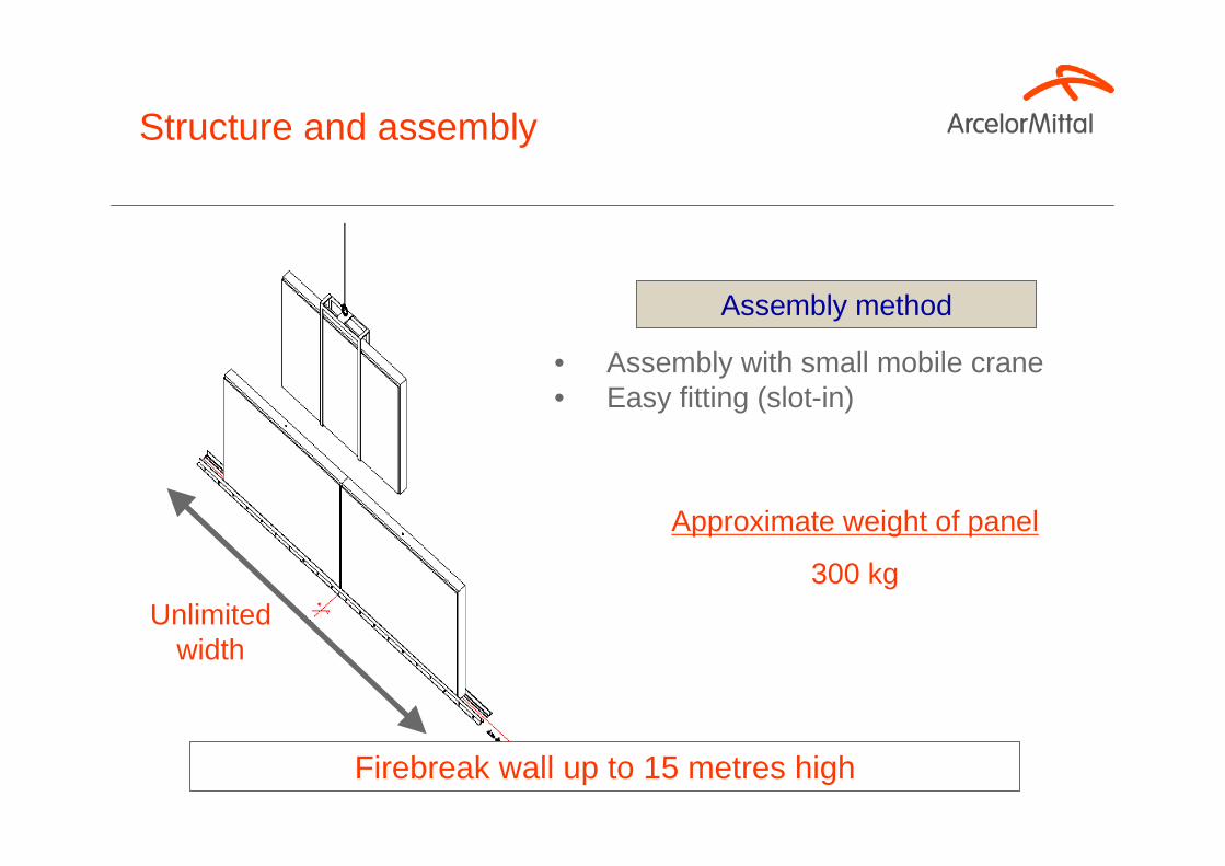
Firebreak wall up to 15 metres high
Assembly method
• Assembly with small mobile crane• Easy fitting (slot-in)
Unlimited width
Approximate weight of panel
300 kg
Structure and assembly

Horizontal and vertical assembly
Aluzinc strip, 1 mm thick
Aluzinc facing, 1 mm thick
Steel hat-section rail, 1.2 mm thick
Palusol PM
A2 stainless steel Lag screw TH 6 x 80
ZN steel self-tapping screw TH 4.7 x 16
Structure and assembly: joints

• Time savings• Clean, dry worksite• Lower assembly costs
Floor fastening
- Generally no need to strengthen an existing concrete slab
- “U” or flat section performs fastening rail and levelling functions
- Fastening on existing concrete
Floor surface pressure around 1 kg/cm 2 for partition 15 metres high
Concrete
Concrete floor slabLevelling mortar base (thickness as required)
Structure and fitting:Floor fastening

Lifting spreader supplied

RoofFaçade
50 cm
1 m
Structure and fitting: Extention through façade and roof

Section III
Firewall FirebreakCSTB Certification test
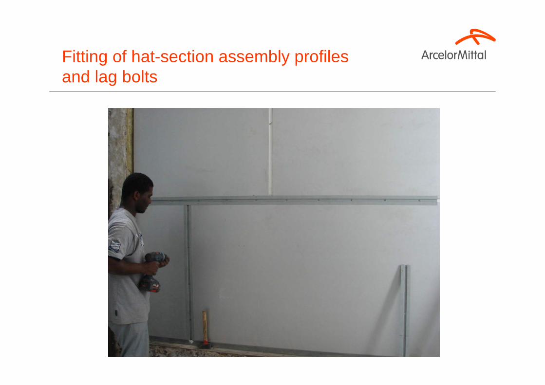
Fitting of hat-section assembly profiles and lag bolts

Intumescent strip and screw-down closuresheet
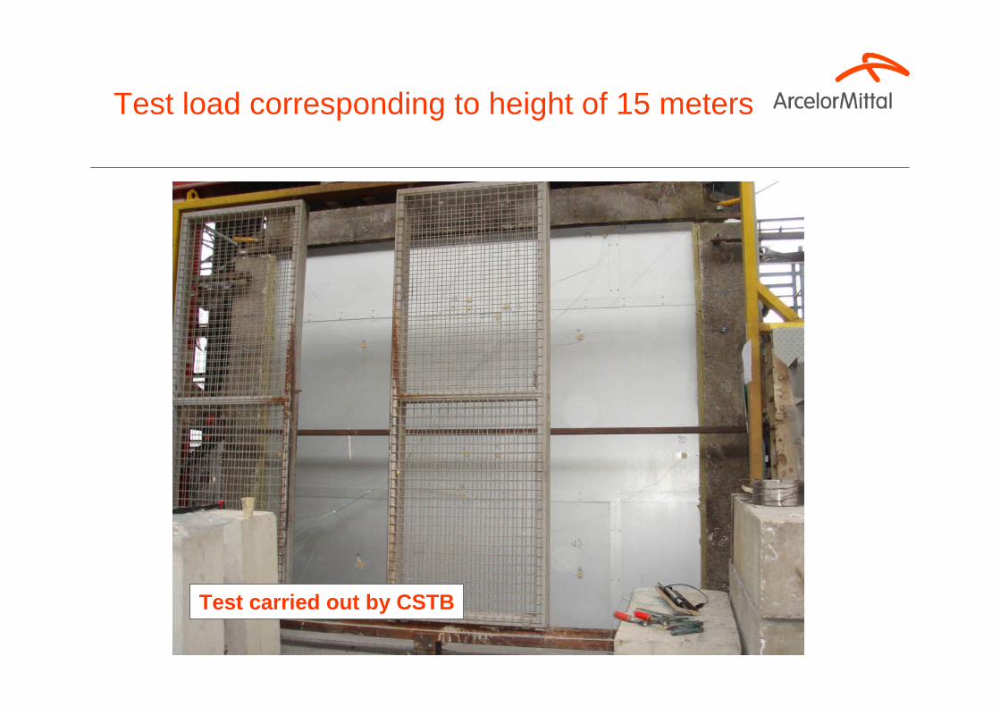
Test carried out by CSTB
Test load corresponding to height of 15 meters
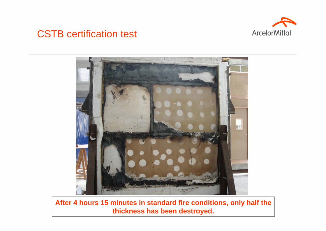
After 4 hours 15 minutes in standard fire condition s, only half the thickness has been destroyed.
CSTB certification test

CSTB evaluation & test report

II – Findings
II.1 – Rating criteria: standard
II.1.1 – Load-bearing capacityDuration: 240 minutes
II.1.2 – Flame and fume seal-offDuration: 240 minutes
II.1.3 – Heat insulationDuration: 240 minutes
II.2 – Laboratory evaluation basis
II.2.1 – Test report n° RS07-050 (self-supporting wall, load 1162 daN / ml)
CSTB evaluation & rating report

Section IV
Firebreak system Promotion & Development

Exhibition at Batimat trade show in Paris, November 2007

Exhibition at Expoprotection trade show in Paris, November 2008
In recognition to its innovative characteristics, the Firebreak Wall 4H has received a the Innovation award

• Firebreak 2 hours : height 15 m
• Firebreak 1 hour : height 12,5 m
• Acoustic tests of Firebreak 4hours
• Getting European Technical Accreditations
• Floor and ceiling firestop=> High Buildings
Development

Section V
Extra Part on Fire regulation

…require compliance with structural fire-resistance rating criteria
Regulations

• R (SF): mechanical resistance time under standard test conditions of ISO 834 � load-bearing structures
• RE or E (PF): flame and fume seal-off time � partition structures (slabs, walls)
• REI or EI (CF): heat insulation (140°C on face opposite to fire)� partition structures (slabs, walls)
Fire resistance rating criteria

General textsDecrees, orders, circulars
French Ministry of Ecology & Sustainable Development
• Decree of 5 August 2002 on prevention of disasters in covered warehouses requiring authorization under item 1510 (Official Journal of 1 January 2003, page 50)
• Decree giving innovative specification of clear objectives
Regulation and decrees

Article 6 (� specific objectives)
“In general terms, construction measures seek to ensure that collapse of a particular item (wall, roof, pillar, beam, etc.) does not lead to a domino-effect collapse of the building structure as a whole (typically the neighbouring storage cells, or the partitions between them), and that if collapse occurs it does so within rather than outside the initial fire zone.”
Measures on fire resistance of warehouses

• Survival is possible up to 80°C (or possibly 150°C for firefighters in special clothing).
• Usual materials resist temperatures up to 500°C and beyond.
• When materials reach 500°C, the local ambient temperature is much higher.
• Conclusion: Conditions have ceased to be life-sustaining long before structural collapse occurs in the fire
Physical data

• Local collapse of a structure in a fire is not a catastrophe in itself provided that we can be certain there are no people alive in thecollapse zone….
BUT
• Collapse of one item must not lead to collapse in structures notaffected (or less affected) by the fire, which may not yet have been vacated or which may be occupied by firefighters � Domino collapse must be avoided.
In most cases, the feasibility of rescuing victims in a building on fire depends not so much on the fire resistance of the structure as on the risk of domino collapse.
Consequences

Metal racks absorbed domino collapse of the structure in pre-stressed concrete
Domino collapse, illustration

• Metal structures usually respond well to this criteria.
• A design guide is available, based on a parametric study by CTICM (SCMF site).
• CTICM = Centre Technique et Industriel de la Constru ction Métallique (Steel construction technical and industrial institute)
• SCMF = Syndicat de la Construction Métallique de Fran ce (French Constructional Steelwork Association)
Objective: inward collapse kinematics

Article 9
Storage cells should be limited in surface area to reduce the amount of combustible material burning in the event of fire, andprevent fire propagating from one cell to another.
Storage cells should not exceed 3,000 square metres if there is no automatic fire extinguishing system, or 6,000 square metres if there is an automatic fire extinguishing system.
« Item 1510 » storage warehouses : compartmentalization and layout

Article 8
Storage warehouses should be split up into cells to reduce the amount of combustible material burning in the event of fire. Compartmentalization should be capable of preventing fire propagating from one cell to another.
To meet this objective, the cells must meet the following requirements:• The partitions between the storage cells must have a firebreak capability of at least two hours.
« Item 1510 » storage warehouses : compartmentalization and layout

• The partitions must continue through the roof and extend at least 1 metre above it at this point. Either the roof must be covered with a protective strip extending over a width of least 5 metres on either side of the partitions, or alternatively, if warranted, a dry standpipe may be fitted along the partitions to afford similar protection.
• Unless the outer walls have a one-hour firebreak capability, cell partitions must extend through the outer walls and terminate either in a section 1 metre wide along the outer walls, or extend for 0.50 metres beyond the outer walls.
« Item 1510 » storage warehouses : compartmentalization and layout

Fire partition walls may be arranged in any configuration with respect to the load-bearing structure.
Storage compartmentalization and layout

Regulatory minimum requirements can be tightened by additional requirements specific to insurance companies.
APSAD Regulation

2 – Firebreak partitions
2.1 – Purpose
A firebreak partition (FBP) separates two buildings or two parts of the same building so that fire breaking out on one side of the partition will not propagate to the other side.
2.2 – Behaviour in fire
A firebreak partition must be rated to at least REI 240, whichever side is exposed to the fire risk. The fire resistance of the firebreak partition must be validated by an accredited technical inspector or by a worksite report issued by an accredited laboratory, as appropriate. A work completion report must be submitted to the project owner in two copies, one for the insurance company.
Validation concerns the fire resistance of load-bearing items, filling materials and the fittings of openings and passageways through the partition.
Ouvrages séparatifs coupe-feu Règle ARSADR15 – Edition xx 2007.0
APSAD Regulation

Firebreak partitions must extend at least 1 metre above the highest point of an area extending 7 metres either side of the partition. (See figure 2.4.1.1.a.)
Figure 2.4.1.1.a – Firebreak extending above roof between two buildings of same height
If the partition separates buildings of different heights, this requirement applies to the higher of the two buildings. (See figure 2.4.1.1.b.)
Figure 2.4.1.1.b – Firebreak extending above roof between two buildings of different heights
This measure is to ensure that fire cannot propagate through the firebreak, by direct action of the flames or by radiated heat, and to provide a screen protecting firefighting personnel as they work to extinguish the fire.
2.4.2 – Extension through outer walls
2.4.2.1 – Title pending
Firebreak partitions must extend 0.5 metres clear beyond the outer face of an outer wall. (See figure 2.4.2.1.a.)
Figure 2.4.2.1.a – Firebreak extending beyond outer wall
This requirement may be lifted if there is a strip rated to EI 120 at least 2 metres wide along the whole height of the outer wall either side of the partition, in material rated A1 or A2s1d0, with no opening it it. (See figure 2.4.2.2.a.)
Figure 2.4.2.2.a – Exception to extension through outer wall: façade with no openings, rated EI 120, in material rated A1 or A2s1d0
Partition 1 metre above highest point in this area
Top view
Building A Building B
FBP
Top view
Building A Building B
Facade
Facade
FBP
FBP
APSAD Regulation

2.5.2 – Openings (unobstructed bays)
Openings in a firebreak partition must be fitted with automatically closing double doors rated EI 90 and E1 120, meeting the design and fitting requirements specified in APSAD rule R 16. (See figures 2.5.1.a and 2.5.1.b.)
Figure 2.5.1.a – Double firebreak door
Bays must not be more than 3.8 metres wide or 4.4 metres high.
Door closure must be operated by means of an automatic detection system or independent type I sensor-triggers.
The materials surrounding the openings (lintels and jambs) must be strong enough to support the weight of the firebreak doors and withstand the impacts of repeated open-close action. If the material is not strong enough (cellular concrete, for example), a special frame must be built on which to fit the door mechanisms. (Figure 2.5.1.c.) Metal lintels are not allowed.
Horizontal sectionFBP
FBP
Firebreak door, open
Firebreak door, closed
APSAD Regulation

Compliant with APSAD
rule R16
EI 120Single doors EI 90 &
A 120 (inner face)
Single doors E 90 (outer
face)
A1 or A2s1d0
Not applicableNot applicableNot applicable
REI 90 for outer face
and EI 90 for other faces
Fireproof compartment
Compliant with APSAD
rule R16
EI 120Automatic-closure
single doors, E 120
A1 or A2s1d0. ”Fragile”faces not allowed if
rack parallel to ordinary
wall
As firebreak partition, except for concrete roofs
Load-bearing by sliding supports or
fuse links.
No requirement
REI 120Ordinary partition
EI 120EI 120Automatic-closure doors, EI 120
No requirement
Extension 1 metre above roof. Extension 0.5
metres beyond façade or 1 metre along façade on either side. Roof covered
with protective strip 5 metres either side
Target result: no domino collapse and no outward collapse of fire outbreak cell.
No requirement
REI 120Regulatory firebreak partition
Compliant with APSAD
rule R16
Not allowedAutomatic-closure double
doors, EI 90 and E 120.
A1 or A2s1d0
Extension 1 metre above roof and A1 or A2s1d0
protective strips 5 metres either side.
Load borne by means of brackets
or consoles and sliding supports.
Load-bearing capability allowed
for double firebreak partition.
YesREI 240 or EI 180 on both
faces of double-face
firebreak partition.
Firebreak partition
ConveyorsVentilation & air cond-
itioning ducts
OpeningsStructure materials
Extension through roofLoad bearingSelf-supporting
Fire resistance
Type of partition
APSAD Regulation

APSAD R15 rule: self-supporting firebreak walls wer e required for reasons of symmetry, which appeared logical at the time, but notnow.
Metal-frame firebreak walls are not allowed unless they have a double face. (See section 2.7.)
APSAD Regulation

As an initial approximation, the firebreak capability of a wall in solid prefabricated concrete panels can be calculated using the simple rules set out in standard P 92-701 (DTU fire concrete), as shown in the table below. These rules apply two walls with a slenderness ratio no more than 50. The walls may be exposed to fire on one or both sides.
17.51511976Thickness (cm)
Non-load-bearing walls
252015121110Thickness (cm)
Load-bearing walls
4 hour
s
3 hours
2 hour
s
1 ½hours
1 hour
½hour
Firebreak capability
Fitted in front of concrete pillar
Concrete framework
Concrete frame
Fireproof joints between panels
Variant: panels fitted between
reinforced concrete pillars
Stringer
Frame
Traditionnal construction by concrete pillarsembedded in the floor

Wall
Initial position
Deformed position
Convex deformation on side exposed to heat
BUT… deformation of free-standing (i.e. self-supporting) wall embedded in floor

The wall leans outward from the fire if not free to rotate at the foot.
This goes against the aims of item 1510.
Self-supporting firebreak walls:potentially dangerous
• There is no straightforward, reliable method for designing a self-supporting wall compliant with standards. Resort must be made to sophisticated calculation models that are not in current usage.
• Former rules do not allow for the effect of temperature gradientwhen determining stress. (Text in extenso in R15 till 2007.)
• But the temperature gradient, and the second-order effects thereof, is the main cause of wall collapse.
Former rules (APSAD R15)

• Current recommendations (APSAD R15) should come under serious critical review.
• Embedded pillars and outer façade shear walls should be prohibited if they can be exposed to high temperature gradients.
• Interior firebreak walls embedded in the floor should only be allowed if the effects of expansion and the resulting additionalstress on neighbouring structures can be properly evaluated.
Conclusion

Not if we can be sure that collapse will be in the right direction without risk for the wall.
Is full chaining really necessary?

In the scenario to the right, the wall curves less, so the weight offset is less, and the risk of collapse is toward the fire rather than away from it.As we said previously, thanks to its steel structure the Firebreak wall is
not concerned by this problem
Wall embedded at foot and free at top
Wall supported horizontally at foot and top
Wall curves gradually
Classical deformation and possible solution?

Thank you for your attention
Contacts :
Fabrice Sokolowsky, Innovation & Development Manager
Frédéric Goujon, Project Manager