the business case for spiral development in heavy-lift … · · 2013-04-10the business case for...
TRANSCRIPT

American Institute of Aeronautics and Astronautics
1
The Business Case for Spiral Development in Heavy-Lift
Launch Vehicle Systems
Rebecca A. Farr*
NASA Marshall Space Flight Center, AL 35812
David L. Christensen†
Madison, AL 35758
and
Edward L. Keith‡
La Verne, CA 91750
Performance capabilities of a specific combination of the Space Shuttle external tank and
various liquid engines in an in-line configuration, two-stage core vehicle with multiple
redesigned solid rocket motor strap-ons are reexamined. This concept proposes using
existing assets, hardware, and capabilities that are already crew-rated, flight certified, being
manufactured under existing contracts, have a long history of component and system ground
testing, and have been flown for over 20 yr. This paper goes beyond describing potential
performance capabilities of specific components to discuss the overall system feasibility—
from end to end, start to finish—describing the inherent cost advantages of the Spiral
Development concept, which builds on existing capabilities and assets, as opposed to starting
up a “fresh sheet” heavy-lift launch vehicle program from scratch.
I. Introduction
N February 2004, the NASA Vision for Space Exploration called “for a “building block” strategy of human and
robotic missions to achieve new exploration goals . . . . Robotic missions to the Moon would begin no later than
2008, followed by an extended human expedition as early as 2015. Lunar exploration would lay the groundwork for
future exploration of Mars and other destinations. A new spacecraft to support these journeys—the crew exploration
vehicle—would be tested before the end of this decade,” 5 yr from now.
Mission scenarios underscore the need for a heavy-lift capability significantly greater than anything available
today. To design and fly a viable crew exploration vehicle within 5 yr and a long-term Lunar Transportation System
within 10 yr in the current budget environment will be a challenging task to say the least. Hope of success can come
only from considering the overall system feasibility—from end to end, cradle to grave—and the inherent costs of
development, long-term operations, maintenance, and upgrades from the very beginning of the effort.
In today’s budgetary environment and with the target dates described above, key assets to leverage for success
are existing capabilities used in a “building block” approach. In this paper, the authors provide a conceptual design
of a large chemical rocket that uses available technology and hardware and is a part of a larger transportation
system, incorporating a wide range of capabilities whose management and growth are based on Spiral Development
principles. This concept is in agreement with studies that propose development of expendable vehicles for both crew
transport and unmanned, very heavy lift cargo transport.1
The Spiral Development process is now being widely used for large Government program acquisitions and lends
itself to the project described here. The main advantage of this concept is that it builds on existing capabilities and
* Propulsion Test Engineer, 14-Inch Trisonic Tunnel Test Laboratory, Propulsion and Fluid Systems Test Division,
ET12, Engineering Directorate, AIAA Member † Retired, AIAA Associate Fellow
‡ Retired, AIAA Member
I
https://ntrs.nasa.gov/search.jsp?R=20050209905 2018-06-14T21:19:49+00:00Z
American Institute of Aeronautics and Astronautics
2
assets, as opposed to starting up a “new sheet” vehicle program from scratch. Spiral Development designs
recombine existing assets in new configurations to function in extrapolated operating conditions.
This particular description of a very large space cargo carrier is provided as an example of what could be
accomplished using existing space transportation system elements—solid rocket motors (SRMs), tanks/tooling,
liquid rocket engines, facilities—and the organizations, industries, vendor base, and qualified personnel already
involved in closely related activities.
Certain modifications will be required to adapt new propulsion modules, such as liquid oxygen (lox)/kerosene
(RP-1) rocket engines—Lockheed Martin Atlas 5 RD-180 are baselined—to the base of a propellant tank which
could use available Space Shuttle external tank (ET) tooling. Likewise, the ET lox tank would be reconfigured and
an interstage structure incorporated to accommodate a large upper stage and the dynamic loading needed for the
very large payloads that could be launched with this axisymmetrical design. Also, new attachments will be
incorporated into the redesigned ET-based tank structure, or core stage, to accommodate a cluster of up to six Space
Shuttle SRMs (designated as the RSRM by NASA). Some modification of the Space Shuttle main engines (SSMEs)
or the Boeing Delta 4 RS-68 engine will likewise be required to use these flight-qualified propulsion systems on a
large (ET based) upper stage, particularly to allow starting the engines at upper altitudes (not currently practiced on
the Space Shuttle or Delta rocket systems).
The “NOVA Class” described in this paper is considered to be large enough—with over twice the gross liftoff
weight of the Saturn 5—to be near an “end of growth” level of maturity and capable of a number of future
mission/payload needs. It could be downsized for certain missions by reducing the number of RSRMs, as is
currently done with the “building block” approach of using various numbers of SRMs on the Atlas and Delta
Evolved Expendable Launch Vehicle (EELV) programs.
A number of trades, assessment of issues, and design considerations are still required to achieve the functional
and operational capabilities, performance, safety, dependability, and life cycle affordability needed for the success
of this ambitious concept.
II. What is “Spiral Development”?
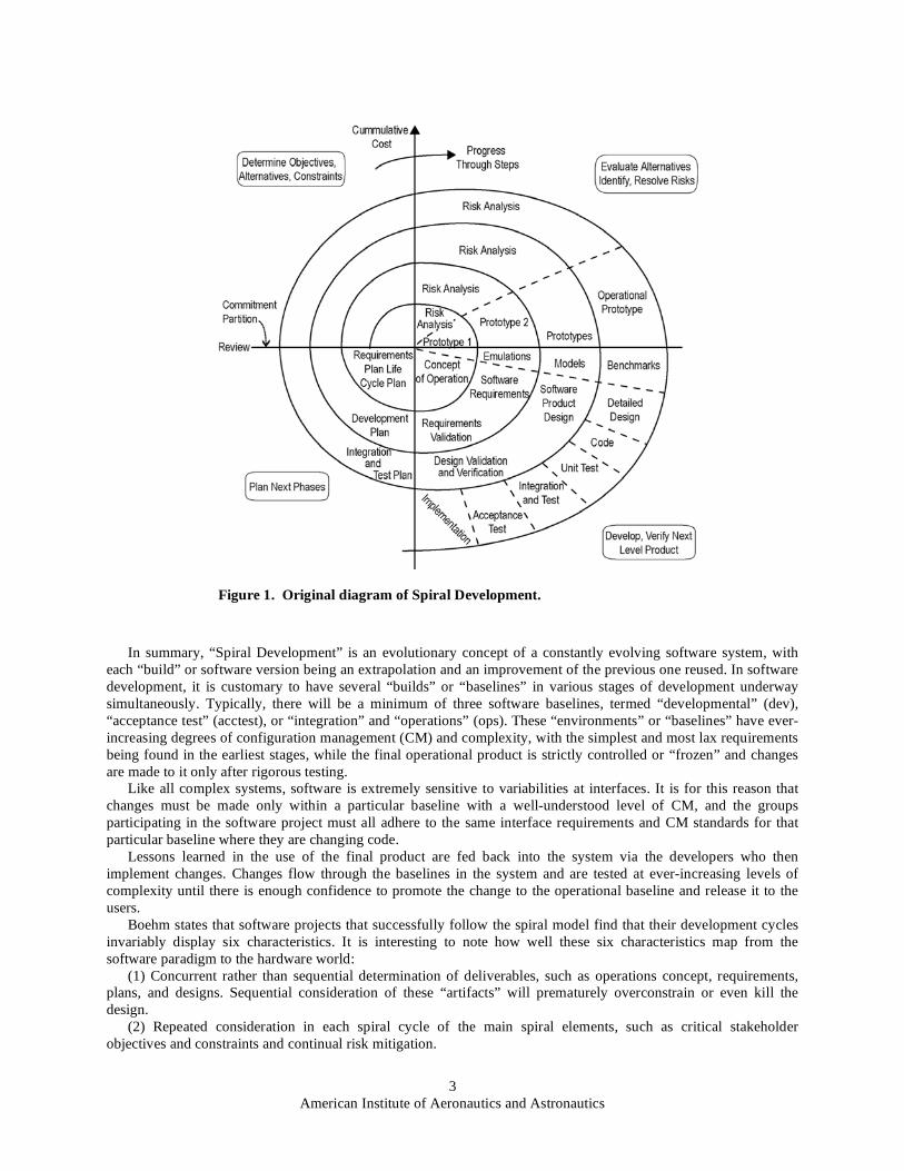
The concept of Spiral Development, as applied to software development efforts, was described by Barry
Boehm.2 Figure 1 is a redrawing of the original spiral model diagram published by Boehm.
2 It captures the major
spiral model features: cyclic concurrent engineering, risk-driven determination of process and product, growing a
system via risk-driven experimentation and elaboration, and lowering development cost by early elimination of
nonviable alternatives and rework avoidance. As a result of planning and risk analysis, different projects may choose
different processes. That is, the spiral model is actually a risk-driven process model generator in which different risk
patterns can lead to choosing incremental, waterfall, evolutionary prototyping, or other subsets of the process
elements in the spiral model diagram. In proceedings from a February 2000 workshop at the University of Southern
California, Boehm further defined Spiral Development as follows: “The spiral development model is a risk-driven
process model generator. It is used to guide multi-stakeholder concurrent engineering of software-intensive systems.
It has two main distinguishing features. One is a cyclic approach for incrementally growing a system’s degree of
definition and implementation while decreasing its degree of risk. The other is a set of anchor point milestones for
ensuring stakeholder commitment to feasible and mutually satisfactory system solutions.”3
He goes on to provide the following definitions of risk, process model, cyclic, and anchor point milestones:
“Risks are situations or possible events that can cause a project to fail to meet its goals. They range in impact
from trivial to fatal and in likelihood from certain to improbable. A risk management plan enumerates the risks and
prioritizes them in degree of importance, as measured by a combination of the impact and likelihood of each. For
each risk the plan also states a mitigation strategy to deal with the risk. For instance, the risk that technology is
unready may be mitigated by an appropriate prototype implementation in an early spiral cycle.
A process model answers two main questions:
• What should be done next?
• For how long should it continue?
Under the spiral model, the answers to these questions are driven by risk considerations and vary from project to
project and sometimes from one spiral cycle to the next. Each choice of answers generates a different process model.
At the start of a cycle, all of the project’s success-critical stakeholders must participate concurrently in reviewing
risks and choosing the project’s process model accordingly. (Risk considerations also apply toward ensuring that
progress is not impeded by stakeholders’ overparticipation.) The cyclic nature of the spiral model [is] illustrated in
Figure 1. Anchor point milestones drive the spiral to progress toward completion and offer a means to compare
progress between one spiral project and another.”
American Institute of Aeronautics and Astronautics
3
In summary, “Spiral Development” is an evolutionary concept of a constantly evolving software system, with
each “build” or software version being an extrapolation and an improvement of the previous one reused. In software
development, it is customary to have several “builds” or “baselines” in various stages of development underway
simultaneously. Typically, there will be a minimum of three software baselines, termed “developmental” (dev),
“acceptance test” (acctest), or “integration” and “operations” (ops). These “environments” or “baselines” have ever-
increasing degrees of configuration management (CM) and complexity, with the simplest and most lax requirements
being found in the earliest stages, while the final operational product is strictly controlled or “frozen” and changes
are made to it only after rigorous testing.
Like all complex systems, software is extremely sensitive to variabilities at interfaces. It is for this reason that
changes must be made only within a particular baseline with a well-understood level of CM, and the groups
participating in the software project must all adhere to the same interface requirements and CM standards for that
particular baseline where they are changing code.
Lessons learned in the use of the final product are fed back into the system via the developers who then
implement changes. Changes flow through the baselines in the system and are tested at ever-increasing levels of
complexity until there is enough confidence to promote the change to the operational baseline and release it to the
users.
Boehm states that software projects that successfully follow the spiral model find that their development cycles
invariably display six characteristics. It is interesting to note how well these six characteristics map from the
software paradigm to the hardware world:
(1) Concurrent rather than sequential determination of deliverables, such as operations concept, requirements,
plans, and designs. Sequential consideration of these “artifacts” will prematurely overconstrain or even kill the
design.
(2) Repeated consideration in each spiral cycle of the main spiral elements, such as critical stakeholder
objectives and constraints and continual risk mitigation.
Figure 1. Original diagram of Spiral Development.
American Institute of Aeronautics and Astronautics
4
(3) Using risk considerations to determine the level of effort to be devoted to each activity within each spiral
cycle, whether it be prototyping, testing, or CM to answer the question “how much is enough”?
(4) Using risk considerations to determine the degree of detail of each deliverable produced in each spiral cycle.
That is, if it is risky to not specify precisely, DO specify. If it is risky to specify precisely, DO NOT specify.
(5) Managing stakeholder life cycle commitments with three anchor point milestones to serve as commitment
points and progress checkpoints. These are life cycle objectives (LCOs), life cycle architecture (LCA), and initial
operational capacity (IOC), where LCOs are the stakeholder’s commitment to support the system’s overall
objectives, LCA is the stakeholders’ commitment to support full life cycle system architecture, and IOC is the
stakeholders’ commitment to accept and support initial operations capabilities.
(6) Emphasis is placed not just on software construction and development aspects, but also on the overall system
and life cycle processes and concerns. Do not just solve a technical problem for the problem’s sake without
understanding how it relates to the overall system design and operability issues. A bad process automated is just a
faster bad process.
In the software development world, constant, rapid change is a given. The evolution of highly complex systems
occurs at a much accelerated rate, possibly 5 to 10 times as quickly as equally complex hardware components and
systems. It is important to note, for purposes of this discussion, that commercial (operational) software products that
do not change and/or keep up with technology and user demand are not on the market for very long. Spiral
Development principles of doing business have evolved in the software industry as a survival strategy.
III. Hazardous Spiral Look-Alikes
Boehm writes, “Many processes are adopted which may seem to be instances of the spiral model, but lack
essential invariants and thus risk failure. Each invariant excludes one or more such process models, which we call
‘hazardous spiral look-alikes.’” The reader is encouraged to see reference 3 for several real-world examples of
Spiral Development look-alikes and how they doomed several projects.
Dangerous assumptions can arise when managers base decisions on processes that are called Spiral Development
but are in fact not. For instance, Boehm states, “All too often, a project will be started on an evolutionary
development approach based on a statement such as, ‘We’re not sure what to build, so let’s throw together a
prototype and evolve it until the users are satisfied.’ This approach is insensitive to several risks corresponding to
the set of assumptions for a successful evolutionary.”
Boehm’s list of dangerous assumptions, rephrased here to apply to a launch system, is as follows:
Bad Assumption No. 1: The initial design is sufficiently satisfactory to key stakeholders that they will continue
to participate in its evolution. In other words, if close attention is not paid to end-user requirements from the very
beginning, even the prototype design may be so far from the users’ needs that they consider it a waste of time to
continue past Preliminary Design Review.
Bad Assumption No. 2: The architecture of the initial design is scalable to accommodate the full set of system
life cycle requirements from the beginning, such as operation, performance, safety, security, testability,
transportability, maintainability, etc.
Bad Assumption No. 3: The operator organization is sufficiently flexible to adapt to the pace of vehicle system
evolution. It is risky to proceed without a life cycle end-to-end architecture, including appropriate contract
management infrastructure that supports evolution.
Bad Assumption No. 4: The dimensions of system evolution are compatible with the dimensions of evolving out
the legacy system it is replacing. Legacy system elements are often too inflexible or limited in capability to be
adapted to desired directions of evolution. In such cases, it is often more cost effective to incrementally design new
system elements from scratch rather than adapt and/or recombine older components in a new way.
A particular example of this would be the X-33 composite hydrogen tank design. Based on new materials
technology, the lightweight tank was a critical structural design element for the vehicle and the rest of the vehicle
was built around the assumption that the tank design would be adequate to structurally support the rest of the
vehicle.
When the tank ruptured during cryogenic ground testing, it became apparent it would have to be greatly
reinforced in order to satisfy the structural loads expected of it. Since the overall vehicle system design was
incapable of absorbing this additional weight, this tank materials’ failure doomed the entire project.
IV. What Spiral Development is NOT
Above all, Spiral Development is NOT a series of quantum leap changes created by introduction of a series of
large, complex, self-contained, but totally unrelated, stand-alone systems, where requirements are “thrown over the

American Institute of Aeronautics and Astronautics
5
fence” and the initiator expects no further interaction with the contractor until the final “working” product is
delivered. This development approach is known in the software world as the “big bang delivery”—for good reason.
Richard Brooksby, Ravenbrook Limited, defines a big bang delivery as follows: “Attempting to meet all the
requirements at once is called the big bang delivery . . . . The development group goes into hyperspace and hopes to
come out somewhere near the desired result. The product is dismantled, and nothing works until the whole thing is
done. A wasteful ‘code freeze’ is needed to put things back together and ‘get it working.’ Furthermore, the product
goes untried until near the end of the cycle, so that errors in requirements, design, or coding are not discovered until
it’s too late to do anything about them. It’s an extremely risky strategy. Errors in requirements are most costly.”4
There are numerous examples of huge, costly “big bang” software development projects in recent years where
this approach failed miserably, at great cost to the Government. In most cases, the initial requirements stated by
well-meaning but uninformed Government representatives were technically challenging, if not unattainable, by the
software developers and depended on immature or nonexistent technologies for success.
Another characteristic of these failed large software projects was severe “requirements creep,” where the
requirements were constantly changing during the course of these projects, requiring much rework and costly
modifications in midstream. Large software projects have a history of repeated failures. Watts S. Humphrey of the
Carnegie Mellon University Software Engineering Institute writes, “The definition of a successful project is one that
completed within 10 percent or so of its committed cost and schedule and delivered all of its intended functions.
Challenged projects are ones that were seriously late or over costs or had reduced functions. Failed projects never
delivered anything . . . half of the smallest projects succeeded, while none of the largest projects did. Since large
projects still do not succeed even with all of the project management improvements of the last several years, one
begins to wonder if large-scale software projects are inherently unmanageable.”5
He then gives two counter examples of two large projects that were actually successful, noting that these
successful software projects “placed heavy emphasis on planning, and both adopted an evolutionary development
strategy with multiple releases and phased specifications.”
In other words, the large successful projects followed Boehm’s Spiral Development model.
Three Notable Software “Big Bang Delivery” Case Study Examples (1) NASA’s Mission to Planet Earth, Earth Observing System Data and Information System (EOSDIS) Core System
(ECS) Report to the Chairman, Committee on Science, Space, and Technology, House of Representatives, February 1992 states,
“Given the significant technological risks inherent in the EOSDIS concept, GAO recommends that the NASA Administrator not award the planned EOSDIS Core System contract until specific plans have been developed and resources identified for (1) prototyping the full range of critical system elements and (2) guiding and accelerating research into key advanced technologies that will be essential for the system’s ultimate success.”
“NASA Finds Problems in EOSDIS Flight Operations Software Development,” April 10, 1998, NASA NEWS RELEASE: 98-60: “Prior to the March 31 delivery, there were three previous incremental deliveries of the software in August 1997, December 1997 and February 1998. Previous versions of the software successfully demonstrated real-time commanding functions with the AM-1 spacecraft. In the new version, however, a number of problems identified in the previous software deliveries were not corrected as expected, and significant problems were found in the new capabilities. Problems include unacceptable response time in developing spacecraft schedules, poor performance in analyzing spacecraft status and trends from telemetry data, and improper implementation of decision rules in the control language used by the flight team to automate operations.”
(2) Federal Retirement Thrift Investment Board’s (OPM) Thrift Savings Plan (TSP) Automated System 07/07/04, http://www.gcn.com/vol1_no1/daily-updates/26516-1.html: “A failed attempt to develop an electronic record keeping
system for the federal Thrift Savings Plan wasted about $36 million in federal retirement assets, according to the investigation results released today by the Senate Governmental Affairs Committee. . . . AMS worked on the project under a four-year, $29.7 million contract, but after four years and $65 million in spending, the system didn’t work . . . . To pay for the contract, $36 million was taken out of the retirement accounts of TSP plan participants and their beneficiaries.”
(3) The Federal Bureau of Investigation’s Virtual Case File System Reuters, January 13, 2005, http://news.zdnett.com/2100-3513-5534809.html: “The [Los Angeles Times] said the FBI recently
commissioned independent studies to determine if any part of the Virtual Case File software could be salvaged. A decision to proceed with new software would add tens of millions of dollars to development costs and render worthless much of a $170 million contract, according to the report . . . . The FBI could seek requests for proposals for a new system this spring, the officials were quoted as saying. The Times said the FBI was no longer saying when the project, originally set to be completed by the end of 2003, might be finished.”

American Institute of Aeronautics and Astronautics
6
V. Applying Spiral Development to the Next NASA Launch System
Now what does all of this software development discussion have to do with spacecraft systems design? Spiral
Development has been employed by the U.S. Air Force (USAF) for several years and is now being embraced by
NASA. However, the USAF has demonstrated that this change in engineering approach must also be supported by
business paradigms and changes in the way contracts are let and managed for success of the approach.6
NASA will face a similar problem in implementing Spiral Development to launch vehicle systems. Rogers et al.
all write: “Spiral development offers the possibility of avoiding technology obsolescence by continually allowing
technology insertion into long-term programs . . . to achieve this benefit, the program systems integrator must have
the flexibility contractually to make the block changes that allow for appropriate technology insertions. Long term,
highly specified performance based contracts may be detrimental to the spiral development concept because they
disincentivize prime contractors from collecting and managing project knowledge and from sharing it with
potentially competitive partners.”7
Obviously, launch vehicles are not software, so the suggested approach, as implemented by the USAF, is slightly
modified from the original software development strategy.
In this case, the Spiral Development of a new NASA launch system would logically leverage some existing
Space Transportation System (STS) and expendable launch vehicle assets to develop a new, heavy-lift launch
vehicle to support the above-stated lunar mission goals. These existing STS and EELV assets and elements, some
slightly modified, are capable of being recombined in new configurations with astounding potential performance
capabilities.
The authors understand that use or derivation of existing rocket elements is not a new idea. Readers will recall
that the use of RSRM, SSME, and ET combinations were explored as a heavy-lift launch vehicle called Shuttle-C in
the late 1980s.8 Additional “Shuttle derived” studies were done more recently under the program “Magnum,” to be
used as a heavy-lift vehicle by NASA and the Department of Defense. The heavy-lift capabilities and potential
versatility of these configurations has been shown in numerous ways and study combinations.
VI. A Specific Design Example of a Heavy-Lift Vehicle
A total systems engineering approach will be required to address all aspects of the proposed large space
transportation system. Particular attention should be applied to minimizing all interfaces, applying the use of fail-
safe design principles and also putting to practice the available lessons that have been learned over the past half
century of rocket and space vehicle operational experience. A functional system breakdown structure has been
developed by the Space Propulsion Synergy Team, a group of veteran space engineers and managers, that should be
applied to the overall system.9
In addition, a detailed “concept of operations” should be prepared and other essential analyses performed to help
ensure that all life cycle elements, including costs, are carefully addressed. References 10–12 support this
recommendation. The authors understand that the use or derivation of existing rocket elements is not a new idea. The capabilities
of these recombined STS components have been shown in numerous studies and white papers and is not
questioned.10
Likewise, the aerospace community has very effectively developed the systems engineering approach
for most of the large-scale programs introduced over the past half century. In fact, it was the basis for quickly
reacting to the launch of Sputnik 1 in 1957 and responding with the rapid development of the Saturn 1 space launch
vehicle. This design used the available propellant tank tooling from the U.S. Army Redstone and Jupiter ballistic
missiles and clustering eight liquid rocket engines—based on modifying and simplifying the Jupiter/Thor propulsion
system—which provided an early operation of a 1.5M-lb thrust booster.13
But this is not why they should be used. Many other existing and planned components could yield similar, even
better performance capabilities. The reader is reminded that the launch vehicle itself is just a part of the equation and
should not be designed in a vacuum without considering the rest of the system, specifically how it will be
manufactured, maintained, and operated in the long run. In addition to achieving certain flight performance goals,
systems designers must also optimize ground and flight operations, manufacturing, test, and maintainability costs in
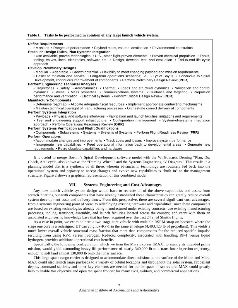
any successful long-term flight project. Table 1 shows a list of tasks—neither complete nor sequential—that must be
performed in the creation of any large launch vehicle system. These tasks are often illustrated in a “Systems
Engineering V Diagram.” From this list, it can be seen that the design of the launch vehicle(s) is only part of the
overall task.
American Institute of Aeronautics and Astronautics
7
Define Requirements
• Missions • Ranges of performance • Payload mass, volume, destination • Environmental constraints Establish Design Rules, Plan Systems Integration
• Use available, proven technologies • U.S., other flight-proven elements • Proven chemical propulsion • Tanks, tooling, valves, lines, electronics, software etc. • Design, develop, test, and evaluation • End-to-end life cycle approach
Develop Preliminary Designs • Modular • Adaptable • Growth potential • Flexibility to meet changing payload and mission requirements • Easier to maintain and service • Long-term operations scenarios; i.e., 50 yr of Soyuz • Conducive to Spiral Development, continuous improvement of components • Perform Preliminary Design Review (PDR)
Perform Engineering Technical Analyses • Trajectories • Safety • Aerodynamics • Thermal • Loads and structural dynamics • Navigation and control dynamics • Stress • Mass properties • Communications systems • Guidance and targeting • Propulsion performance and verification • Electrical systems • Perform Critical Design Review (CDR)
Manufacture Components • Determine roadmap • Allocate adequate fiscal resources • Implement appropriate contracting mechanisms • Maintain technical oversight of manufacturing processes • Orchestrate correct delivery of components
Perform Systems Integration • Payloads • Physical and software interfaces • Fabrication and launch facilities limitations and requirements • Test and engineering support infrastructure • Configuration management • System-of-systems integration approach • Perform Operations Readiness Review (ORR)
Perform Systems Verification and Flight Qualifications • Components • Subsystems • Systems • Systems of Systems • Perform Flight Readiness Review (FRR)
Perform Operations • Accommodate changes and improvements • Track costs and losses • Improve system performance • Incorporate new capabilities • Feed operational information back to developmental areas • Generate new requirements • Retire obsolete capabilities and hardware
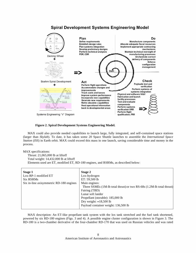
It is useful to merge Boehm’s Spiral Development software model with the W. Edwards Deming “Plan, Do,
Check, Act” cycle, also known as the “Deming Wheel,” and the Systems Engineering “V Diagram.” This results in a
planning model that is a synthesis of all three, wherein advances in technology are routinely fed back into the
operational system and capacity to accept changes and evolve new capabilities is “built in” to the management
structure. Figure 2 shows a graphical representation of this combined model.
VII. Systems Engineering and Cost Advantages
Any new launch vehicle system design would have to recreate all of the above capabilities and assets from
scratch. Starting out with components that have already established these characteristics can greatly reduce overall
system development costs and delivery times. From this perspective, there are several significant cost advantages,
from a systems engineering point of view, to redeploying existing hardware and capabilities, since these components
are based on existing technologies already being manufactured under existing contracts; use existing manufacturing
processes, tooling, transport, assembly, and launch facilities located across the country; and carry with them an
associated engineering knowledge base that has been acquired over the past 24 yr of Shuttle flights.
As a case in point, we examine here a two-stage core vehicle with multiple RSRM strap-on boosters where the
stage one core is a redesigned ET carrying lox-RP-1 in the same envelope (4,493,423 lb of propellant). This yields a
much lower overall vehicle structural mass fraction that more than compensates for the reduced specific impulse
resulting from using RP-1 versus hydrogen. Reduced complexity, associated with handling RP-1 versus liquid
hydrogen, provides additional operational cost benefits
Specifically, the following configuration, which we term the Mars Express (MAX) to signify its intended prime
mission, would yield astounding heavy-lift performance of nearly 340,000 lb to a trans-lunar injection trajectory,
enough to soft land almost 130,000 lb onto the lunar surface.
This large space cargo carrier is designed to accommodate direct missions to the surface of the Moon and Mars.
MAX could also launch large payloads to a variety of orbital locations and throughout the solar system. Propellant
depots, command stations, and other key elements are needed for our in-space infrastructure. MAX could greatly
help to enable this objective and open the space frontier for many civil, military, and commercial applications.
Table 1. Tasks to be performed in creation of any large launch vehicle system.
American Institute of Aeronautics and Astronautics
8
MAX could also provide needed capabilities to launch large, fully integrated, and self-contained space stations
(larger than Skylab). To date, it has taken some 20 Space Shuttle launches to assemble the International Space
Station (ISS) in Earth orbit. MAX could exceed this mass in one launch, saving considerable time and money in the
process.
MAX specifications:
Thrust: 21,065,000 lb at liftoff
Total weight: 14,432,000 lb at liftoff
Elements used are ET, modified ET, RD-180 engines, and RSRMs, as described below:
Stage 1
Lox-RP-1 modified ET
Six RSRMs
Six in-line axisymmetric RD-180 engines
Stage 2
Lox-hydrogen
ET: 59,500 lb
Main engines:
Three SSMEs (1M-lb total thrust) or two RS-68s (1.2M-lb total thrust)
Fairing (TBD)
Lunar soft lander
Propellant (storable): 185,000 lb
Dry weight: 18,500 lb
Payload container weight: 136,500 lb
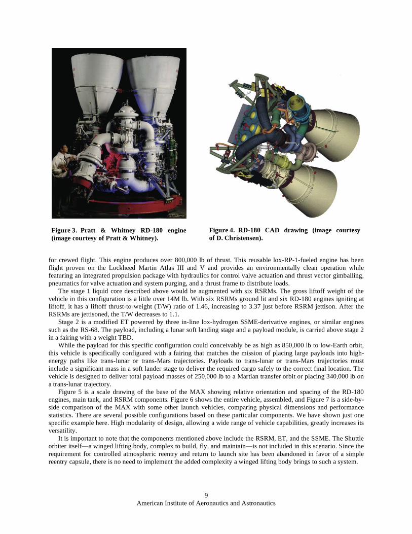
MAX description: An ET-like propellant tank system with the lox tank stretched and the fuel tank shortened,
powered by six RD-180 engines (Figs. 3 and 4). A possible engine cluster configuration is shown in Figure 3. The
RD-180 is a two-chamber derivative of the four-chamber RD-170 that was used on Russian vehicles and was rated
Figure 2. Spiral Development Systems Engineering Model.
American Institute of Aeronautics and Astronautics
9
for crewed flight. This engine produces over 800,000 lb of thrust. This reusable lox-RP-1-fueled engine has been
flight proven on the Lockheed Martin Atlas III and V and provides an environmentally clean operation while
featuring an integrated propulsion package with hydraulics for control valve actuation and thrust vector gimballing,
pneumatics for valve actuation and system purging, and a thrust frame to distribute loads.
The stage 1 liquid core described above would be augmented with six RSRMs. The gross liftoff weight of the
vehicle in this configuration is a little over 14M lb. With six RSRMs ground lit and six RD-180 engines igniting at
liftoff, it has a liftoff thrust-to-weight (T/W) ratio of 1.46, increasing to 3.37 just before RSRM jettison. After the
RSRMs are jettisoned, the T/W decreases to 1.1.
Stage 2 is a modified ET powered by three in-line lox-hydrogen SSME-derivative engines, or similar engines
such as the RS-68. The payload, including a lunar soft landing stage and a payload module, is carried above stage 2
in a fairing with a weight TBD.
While the payload for this specific configuration could conceivably be as high as 850,000 lb to low-Earth orbit,
this vehicle is specifically configured with a fairing that matches the mission of placing large payloads into high-
energy paths like trans-lunar or trans-Mars trajectories. Payloads to trans-lunar or trans-Mars trajectories must
include a significant mass in a soft lander stage to deliver the required cargo safely to the correct final location. The
vehicle is designed to deliver total payload masses of 250,000 lb to a Martian transfer orbit or placing 340,000 lb on
a trans-lunar trajectory.
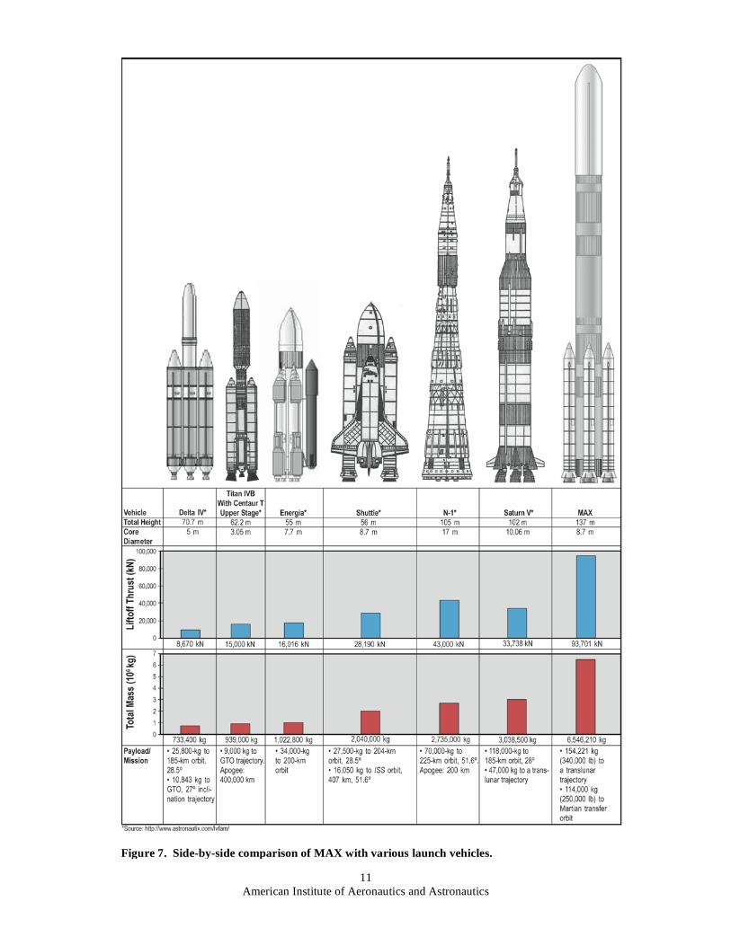
Figure 5 is a scale drawing of the base of the MAX showing relative orientation and spacing of the RD-180
engines, main tank, and RSRM components. Figure 6 shows the entire vehicle, assembled, and Figure 7 is a side-by-
side comparison of the MAX with some other launch vehicles, comparing physical dimensions and performance
statistics. There are several possible configurations based on these particular components. We have shown just one
specific example here. High modularity of design, allowing a wide range of vehicle capabilities, greatly increases its
versatility.
It is important to note that the components mentioned above include the RSRM, ET, and the SSME. The Shuttle
orbiter itself—a winged lifting body, complex to build, fly, and maintain—is not included in this scenario. Since the
requirement for controlled atmospheric reentry and return to launch site has been abandoned in favor of a simple
reentry capsule, there is no need to implement the added complexity a winged lifting body brings to such a system.
Figure 3. Pratt & Whitney RD-180 engine
(image courtesy of Pratt & Whitney).
Figure 4. RD-180 CAD drawing (image courtesy
of D. Christensen).

American Institute of Aeronautics and Astronautics
10
VIII. Pitfalls of Extrapolations
The basic design described above incorporates launch system elements in configuration, assembly, and
operations. However, it is no simple matter to extrapolate their design to a much larger scale. One cannot simply
scale up an existing system to MAX without doing a great deal of engineering analysis work and testing. Analysis
on systems integration, complex interactions of the various structural and dynamic elements, and the new induced
environments created by a new configuration flying in new flight regime conditions must all be done for each new
configuration.
It cannot be understated that recombination of understood elements does not imply or result in well-understood
performance of the new configuration. Nonlinear interaction of parts, aerodynamics, new performance capabilities,
and resulting flight-induced environments should be expected. Existing analysis tools must be expanded and
benchmarked for the new applications by extensive ground testing and analysis.
Figure 5. Footprint of MAX, showing core ET with six RD-180
liquid engines and six RSRM strap-on boosters.
Figure 6. Entire MAX, assembled.
American Institute of Aeronautics and Astronautics
11
Figure 7. Side-by-side comparison of MAX with various launch vehicles.
American Institute of Aeronautics and Astronautics
12
IX. Conclusions
In conclusion, from a systems engineering point of view, a “modular building block” management approach is
desired in designing the new lunar and Mars transportation system. This would be best initiated by using existing
hardware, engineering, software, contractual, and operational assets in the first vehicle designs and then introducing
new methods and technologies over time in a well-planned “Spiral Development” approach.
Whether one is dealing with software development or flight hardware manufacture, unreasonable or unattainable
initial requirements, lack of indepth technical oversight, depending on unproven or nonexistent technologies, lack of
thorough system planning, abrupt design changes, and constantly changing requirements are a recipe for project
failure and should be avoided.
Cost and schedule modelers know that it is faster and less costly to design a system around existing hardware,
technology, and industrial processes then to develop a new system from a truly clean sheet. A heavy-lift launch
vehicle of the Saturn V class or larger requires a very large infrastructure system. It is important for policymakers to
realize that, even allowing for the great deal of work that would be necessary to understand the new dynamic-
induced environments during ascent of a new configuration vehicle and set up all of the other infrastructure using
existing assets and capabilities as a “jump start” is the only way to achieve first flight of a new heavy-lift, crew-rated
vehicle within the targeted 5 yr.
The configuration described herein represents a viable solution that uses large and existing hardware elements to
achieve a launch capability that meets the heavy-lift requirements envisioned for future manned lunar missions
within 5 yr. The wide capability range that can be achieved by this modular approach will likewise meet a very wide
range of mission requirements for many years to come.
Finally, NASA leadership must view this as a long-term effort made up of continuously evolving system of
systems, rather than concentrating on any one vehicle concept to the exclusion of all others, while also attempting to
make that one concept satisfy all possible requirements. Too many times in the past we have spent all our efforts on
delivering a particular highly complex but limited-capability vehicle, then stopped all development efforts on
anything beyond that to apply all available resources to the near-term needs of operating that one vehicle. True
leadership requires a long-range view of the ultimate goals. All of the skills, technologies, resources, and political
support in the world will not guarantee success without good leadership.
Developing this first vehicle is only the first step in the Journey, it is not our final destination. Those who cannot
remember the past are doomed to repeat it, while those who learn from the past, evolve.
References 1Garriot, O. K., Griffin, M., Claybaugh, W., Garvey, J., Jones, T.D., Kohlhase, C., McCandless III, B., O'Neill, W., and
Penzo, P.A., “Extending Human Presence Into the Solar System, An Independent Study for the Planetary Society on Strategy for
the Proposed U.S. Space Exploration Policy,” Planetary Society, July 2004. 2Boehm, B., “A Spiral Model of Software Development and Enhancement,” Computer, May 1988, pp. 61–72.
3Boehm, B., “Spiral Development: Experience, Principles, and Refinements,” Spiral Development Workshop, Special
Report, edited by W. J. Hansen, July 2000, 65 pp., URL: http://www.sei.cmu.edu/cbs/spiral2000/february2000/SR08.pdf. 4Brooksby, R., “Product Quality Through Change Management,” Ravenbrook Limited, URL: http://www.ravenbrook.com/
doc/1999/05/20/pqtcm/. 5Humphrey, W. S., “Why Big Software Projects Fail: The 12 Key Questions,” Carnegie Mellon University, Software
Engineering Institute, Software Technology Support Center, URL: http://www.stsc.hill.af.mil/crosstalk/2005/03/
0503Humphrey.html. 6Hansen, W. J., Foreman, J. T., Albert, C. C., Axelband, E., Brownsword, L. L., and Forrester, E. C., “Spiral Development
and Evolutionary Acquisition,” Special Report CMU/SEI-2001-SR-005, The SEI-CSE Workshop, September 2000. 7Rogers, E., Linde, C., Berkowitz, D., and Singh, T., “WHITE PAPER: Linking Acquisition Strategy to Contract
Performance Over the Product Life Cycle,” Submitted to NASA Exploration Enterprise (Code T), May 17, 2004,
8 pp., URL: http://smo.gsfc.nasa.gov/knowman/documents/whitepapers/PB_Acquisition_Strategy.pdf. 8Christensen, D., Shuttle-C Users Conference—Executive Summary, May 25–26, 1989, Huntsville, AL, pp. 1–14.
9Dankhoff, W., Mitchell, P.; Rhodes, R.; and Penn, J., “Summary of SPST Activities Dedicated to the Achievement of Safe,
Dependable and Affordable Space Transportation,” AIAA 2001-3984, AIAA/SAE/ASME/ASEE Joint Propulsion Conference,
July 8–11, 2001. 10
Christensen, D., “Advances in the Application of Systems Engineering Procedures,” AIAA 96-4433, 1996 AIAA Space
Programs and Technologies Conference, September 24–26, 1996, Huntsville, AL. 11
Hammond, W. E., “Space Transportation: A Systems Approach to Analysis and Design,” AIAA Educational Series, 1999. 12
Blair, J. C., Ryan, R. S., Schutzenhofer, L. A., and Humphries, W. R., “Launch Vehicle Design Process, Characterization,
Technical Integration and Lessons Learned,” NASA/TP—2001–210992, May 2001. 13
Bilstein, R. E., “Stages to Saturn, A Technical History of the Apollo/Saturn Launch Vehicles,” NASA SP–4206,1980.