the br2 matrix replacement and safety upgrades
TRANSCRIPT

THE BR2 MATRIX REPLACEMENT AND SAFETY UPGRADES
F. JOPPEN, G. VAN DEN BRANDE, S. VAN DYCK
BR2 Expert Group, Nuclear Research Centre
Boeretang 200, 2400 Mol, Belgium
ABSTRACT
From February 2015 tot July 2016 the BR2 reactor was stopped for replacement of the beryllium core and accompanying reactor vessel inspection. During this period, a number of safety upgrades were made. These upgrades originated from different requests. Some of the conclusions of the analyses about the protection against severe accidents were still under development. A new regulation on nuclear safety obliges the development of an ageing management system. According to the licence, BR2 is subjected to 10 yearly safety review. June was the due date for reporting the conclusions and proposing an action plan for safety upgrades, which are now being installed. All this projects increased the reliability and the safety of the reactor which was restarted on June 19, 2016.
1 Introduction
The BR2 Material Test Reactor was shut down from February 2015 until July 2016 for replacement of the beryllium core. Although the matrix was not yet end of life, a decision was taken to replace it in order to increase operational flexibility and to reduce fuel consumption. In the past, the replacement operation had already been done two times (in 1979 and in 1996). After unloading the beryllium core, a non destructive inspection of the reactor vessel (which is only accessible at that moment) is required according to the licence. Results of the vessel inspection and the vessel material follow up program confirmed that the vessel can remain in use of a period of more than 10 years.
During the period for the beryllium replacement, a number of other projects about safety upgrade were ongoing. First of all was a 10 year periodical safety review process which is mandatory according to the licence. Another issue was the implementation of some of the systems for protection against the consequences of severe accidents. In order to comply with a new regulation on the safety of nuclear installations a formal system for ageing management was also developed and applied.
2 The BR2 reactor
The BR2 reactor is a heterogeneous thermal high flux engineering test reactor, designed in 1957 for SCK•CEN by NDA [Nuclear Development Corporation of America - White Plains (NY - USA)]. It has been built on the site of the SCK•CEN laboratories in Mol, Belgium. Routine operation of the reactor started in January 1963.
The reactor is cooled and moderated by pressurised light water in a compact core of highly enriched uranium positioned in and reflected by a beryllium matrix. The maximum thermal
flux approaches 1015
neutrons / (cm²·s) and the ultimate cooling capacity, initially foreseen for 50 MW, has been increased in 1971 up to 125 MW. The licence has no specified thermal power limit. Instead, the maximum heat flux on the fuel plates is specified. The total thermal power is of course limited by the heat removal capacity of the primary and secondary circuit.

The main characteristics of BR2 are:
• Maximum heat flux for normal operation: 470 W/cm²
• Maximum heat flux for special applications: 600 W/cm²
• Nominal power: Between 50 and 125 MW
• Maximum thermal neutron flux: 1.2 × 10¹⁵ neutrons / (cm²·s)
• Maximum fast neutron flux (E > 1.0 MeV) 8.4 × 10¹⁴ neutrons / (cm²·s)
• Possible irradiation positions > 100
• Fissile charge at start of cycle 10 to 13 kg 235U.
The reactor is operator in cycles of 3 or 4 weeks, 5 or 6 cycles per year, with the possibility for short cycles. The minimum shut down period between the cycles is 1 week.
3 The beryllium matrix replacement.
3.1 The Beryllium matrix
Fig. 1: Views of the beryllium matrix (side and top view)
The beryllium matrix is a structural element of the BR2 reactor core. The matrix is composed of:
• 64 standard channels with an inner diameter of 80 mm.
Top extention pieces
Beryllium blocks
Lower extension pieces
Support tubes
• 10 channels with an inner diameter of 50 mm at the periphery.
• 5 channels with an inner diameter of 200 mm.
• 12 beryllium filler pieces.
A channel is composed of the beryllium section, with a length of 960 mm, the two stainless steel extension pieces (top and bottom), the lower support tube and the upper guide tube (both also stainless steel). The channels have a complicated form. The axes of the channels are arranged according a hyperboloid (see fig. 1). In this way, the channels are close together in the centre, while at the top and the bottom they are further from each other. This make the core very compact with more space at the vessel head for access to the channel. A disadvantage of this design is that the hexagonal blocks become irregular, with a different form for each radius.
3.2 Irradiation damage of beryllium
During irradiation, helium and tritium are formed in the beryllium. This has two adverse effects: swelling and neutron poisoning. The swelling is the cause for mechanical damage, while the neutron poisoning makes operation of the reactor more difficult. Both effects limit the useful life of the beryllium matrix.
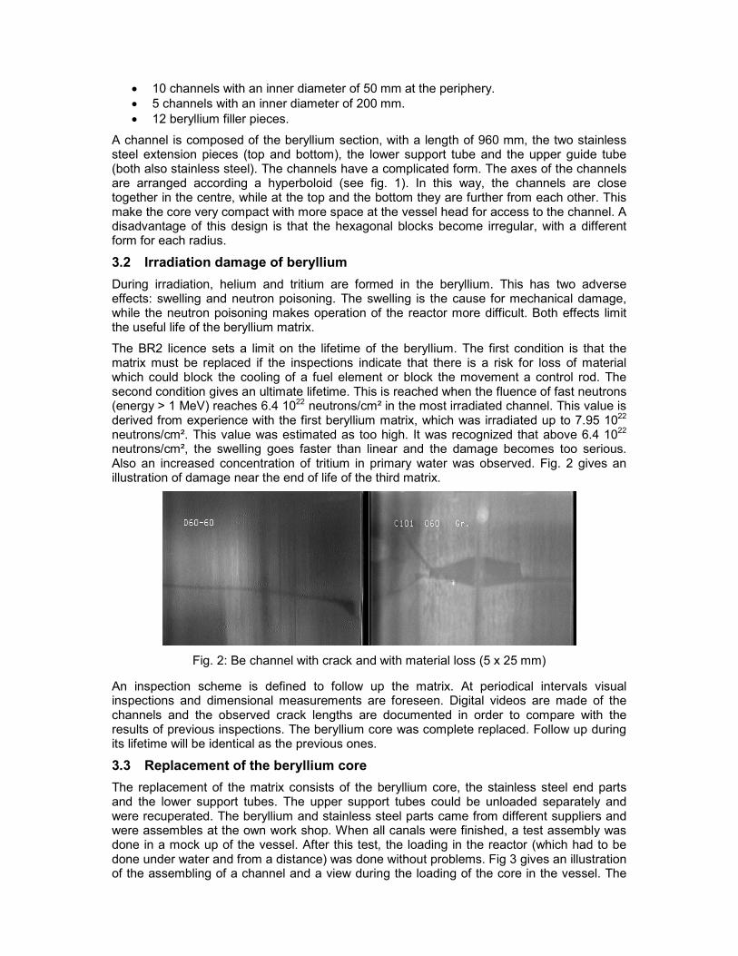
The BR2 licence sets a limit on the lifetime of the beryllium. The first condition is that the matrix must be replaced if the inspections indicate that there is a risk for loss of material which could block the cooling of a fuel element or block the movement a control rod. The second condition gives an ultimate lifetime. This is reached when the fluence of fast neutrons (energy > 1 MeV) reaches 6.4 1022 neutrons/cm² in the most irradiated channel. This value is derived from experience with the first beryllium matrix, which was irradiated up to 7.95 1022 neutrons/cm². This value was estimated as too high. It was recognized that above 6.4 1022 neutrons/cm², the swelling goes faster than linear and the damage becomes too serious. Also an increased concentration of tritium in primary water was observed. Fig. 2 gives an illustration of damage near the end of life of the third matrix.
Fig. 2: Be channel with crack and with material loss (5 x 25 mm)
An inspection scheme is defined to follow up the matrix. At periodical intervals visual inspections and dimensional measurements are foreseen. Digital videos are made of the channels and the observed crack lengths are documented in order to compare with the results of previous inspections. The beryllium core was complete replaced. Follow up during its lifetime will be identical as the previous ones.
3.3 Replacement of the beryllium core
The replacement of the matrix consists of the beryllium core, the stainless steel end parts and the lower support tubes. The upper support tubes could be unloaded separately and were recuperated. The beryllium and stainless steel parts came from different suppliers and were assembles at the own work shop. When all canals were finished, a test assembly was done in a mock up of the vessel. After this test, the loading in the reactor (which had to be done under water and from a distance) was done without problems. Fig 3 gives an illustration of the assembling of a channel and a view during the loading of the core in the vessel. The
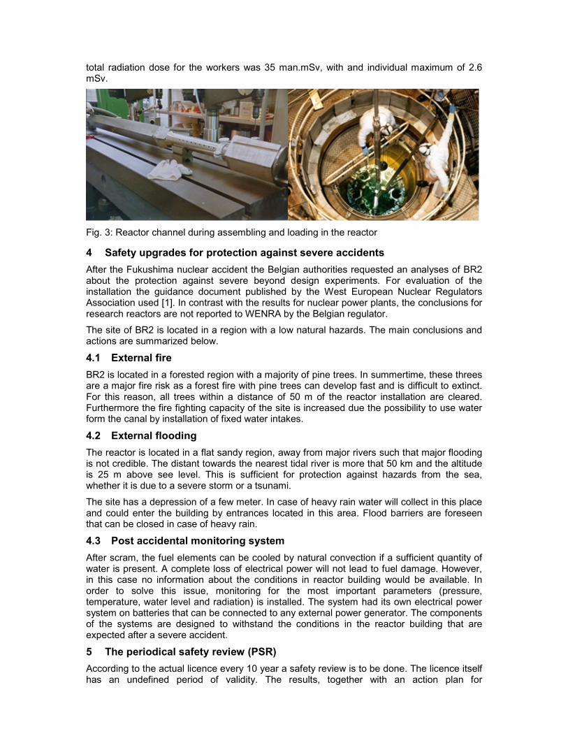
total radiation dose for the workers was 35 man.mSv, with and individual maximum of 2.6 mSv.
Fig. 3: Reactor channel during assembling and loading in the reactor
4 Safety upgrades for protection against severe accidents
After the Fukushima nuclear accident the Belgian authorities requested an analyses of BR2 about the protection against severe beyond design experiments. For evaluation of the installation the guidance document published by the West European Nuclear Regulators Association used [1]. In contrast with the results for nuclear power plants, the conclusions for research reactors are not reported to WENRA by the Belgian regulator.
The site of BR2 is located in a region with a low natural hazards. The main conclusions and actions are summarized below.
4.1 External fire
BR2 is located in a forested region with a majority of pine trees. In summertime, these threes are a major fire risk as a forest fire with pine trees can develop fast and is difficult to extinct. For this reason, all trees within a distance of 50 m of the reactor installation are cleared. Furthermore the fire fighting capacity of the site is increased due the possibility to use water form the canal by installation of fixed water intakes.
4.2 External flooding
The reactor is located in a flat sandy region, away from major rivers such that major flooding is not credible. The distant towards the nearest tidal river is more that 50 km and the altitude is 25 m above see level. This is sufficient for protection against hazards from the sea, whether it is due to a severe storm or a tsunami.
The site has a depression of a few meter. In case of heavy rain water will collect in this place and could enter the building by entrances located in this area. Flood barriers are foreseen that can be closed in case of heavy rain.
4.3 Post accidental monitoring system
After scram, the fuel elements can be cooled by natural convection if a sufficient quantity of water is present. A complete loss of electrical power will not lead to fuel damage. However, in this case no information about the conditions in reactor building would be available. In order to solve this issue, monitoring for the most important parameters (pressure, temperature, water level and radiation) is installed. The system had its own electrical power system on batteries that can be connected to any external power generator. The components of the systems are designed to withstand the conditions in the reactor building that are expected after a severe accident.
5 The periodical safety review (PSR)
According to the actual licence every 10 year a safety review is to be done. The licence itself has an undefined period of validity. The results, together with an action plan for

shortcomings, must be communicated to the regulator. The PSR must take into account long term operation aspect [2]. De subjects for the PSR are those of the IAEA Safety Guide [3], with an additional safety factor concerning radiation protection. An overview is given in figure 4. Long term operation must also taken into account for which also IAEA guidance is used [4]. Because both safety documents are intended for use with power plants, graded approach is used. The conclusion of the PSR are published by the Federal Agency for Nuclear Control [5].
The different safety factors are divided in categories. A number of issues are common for all installations on the site (SF’s 12 to 15). These are treated on site level. Other depend on the specific installation and are analysed by the operating personnel.
Evaluation of SF1 (Plant Design) showed that the actual design still guarantees the safe operation of the reactor. A limited number of design upgrades were identified and will be implemented next years.
Update of the deterministic safety analyses (SF 5) was a major task. The safety cases for normal operation and transients were still based on old hand calculations and outdated calculation codes. In the framework of the PSR all cases have been recalculated, using actual validated codes. Additional transients have also been studied. The basis for the validation of the calculation are the hydraulic tests done during the initial start of the reactor in 1963. For this test fuel elements with measurement of the temperature of the cladding were loaded. Different loss of pressure and lose of flow situations were created and the temperature evolution on the cladding was followed. The results of these tests were used to validate the actual calculation codes.
Fig. 4: Subjects of the Periodical Safety Review 2016
For steady state operation calculation is made with the PLTEMP code [1]. This code is specially suited for plate type fuel elements. It calculates the heat flux on the fuel plates as a function of the flow rate, the inlet temperature and pressure of the fuel channel. The limits for

Onset of Nucleate Boiling, Full Developed Nucleate Boiling (DNB), Onset of Flow Instability (FI) and Critical Heat Flux (CHF) are also calculated. The safety criterion for BR2 is that the heat flux must be lower than the limit for ONB. The code justifies the operational limit on the heat flux of 470 W/cm². A heat flux of 600 W/cm² should be acceptable. Routine operation up to this limit is not allowed due to the fact that it was not tested in all transient conditions.
For anticipated transient operation the PARET code is used [2]. The code calculates the fuel temperature as a consequence of reactivity insertion. It is used to check that no cladding overheating occurs during transients. Both protected and unprotected reactivity transient are calculated. The analyses confirms the actual safety limits for maximum allowable reactivity transients and the requirements for the control rods.
In addition to the recalculation of the existing cases, further studies were made for more severe beyond design transient. For this analyses, a RELAP model of BR2 is used. If RELAP is used for research reactors, it must be kept in mind that the code is developed and validated for power reactors. Essential differences are the much lower temperature and pressure, and the higher quantities of water. Natural convection cooling is for most research reactors a common cooling mode. In order to check that the RELAP model gives correct predictions, the hydraulic tests done during the commissioning of the reactor are simulated and the predicted results are compared with the measurements. An example of this comparison is given in figure 5 for the loss of flow test. For the actual model sufficient agreement is obtained and the RELAP model can be used to study transients that were not tested.
Fig. 5: Comparison between experimental results and RELAP calculation for loss of flow
Probabilistic safety analyses (SF5) is according to the IAEA safety guides not applicable to research reactor. For BR2 a PSA was made and the results were reviewed to assure that all components that were identified as safety important are considered in the ageing management program. Further development of the PSA is not foreseen.
A remark can be made about plant design (SF1). For an installation that is designed and build nearly 60 years ago, it is difficult to collect all design information. For BR2, a lot of documentation is still available but gaps will still remain.
For the other safety factors, an update van the actual situation is made.
6 Ageing Management
The Belgian regulation on the safety of nuclear installations, which is the execution of a European Directive requires an ageing management program for nuclear reactors. A Plant Assessment Program (PAM) has been defined in order to fulfil the requirements of this legislation. The PAM program consists of three main phases: Asset Configuration
Management (ACM), Installation Concept Management (ICM) and Work order Management and Skills (WMS). The project covers also 3 safety factors of the PSR (SF2, 3 and 4).
The first task is to make an inventory of all structures, systems and components (referred to as assets) in the installation. The level of detail should be limited to what is in general maintainable or replacement as a unit. A practical way to perform task is to list all items that are mentioned on flow sheets of the installation. Electrical and instrumentation drawing give also useful information. At this moment 2304 assets are identified for BR2.
Assets were evaluated using three parameters: safety, operational impact and replacement cost. For each different scores were given:
1. Safety (SS):
• Score 0 is given for a safety critical asset. Failure leads directly to a risk for the control of the reactivity, exposure to irradiation above the applicable thresholds, the release of radioactive elements to the environment above the applicable thresholds or severe/fatal work accidents.
• Score 1 is given to assets with implication on safety. Their failure leads to the release of radioactivity within the building, the loss of a defence-in-depth level for risks that could lead to a safety score 0 or which have a significant contribution to the Core Damage Frequency, as indicated by the Probabilistic Safety Assessment of BR2.
• Score 2 are assets without any safety function.
2. Operational impact (OS):
• Score 1 are assets required to operate the reactor and whose failure or unavailability leads to a reactor shutdown of more than one month. This corresponds to a major cost or loss of revenue.
• Score 2 is given to assets required to operate the reactor and whose failure or unavailability leads to a reactor shutdown of more than 5 days, but less than one month. This corresponds to a moderate cost or loss of revenue.
• Score 3 are assets required to operate the reactor and whose failure or unavailability leads to a reactor shutdown of less than 5 days. This corresponds to a minor cost or loss of revenue.
3. Replacement cost (RS)
• Score 1 are assets considered to be irreplaceable.
• Score 2 is given to assets with a high replacement cost
• Score 3 is given to assets with a moderate replacement cost
• Score 4 are assets with a low replacement cost
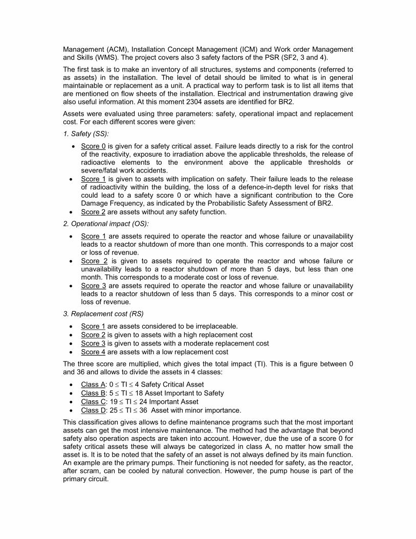
The three score are multiplied, which gives the total impact (TI). This is a figure between 0 and 36 and allows to divide the assets in 4 classes:
• Class A: 0 ≤ TI ≤ 4 Safety Critical Asset
• Class B: 5 ≤ TI ≤ 18 Asset Important to Safety
• Class C: 19 ≤ TI ≤ 24 Important Asset
• Class D: 25 ≤ TI ≤ 36 Asset with minor importance.
This classification gives allows to define maintenance programs such that the most important assets can get the most intensive maintenance. The method had the advantage that beyond safety also operation aspects are taken into account. However, due the use of a score 0 for safety critical assets these will always be categorized in class A, no matter how small the asset is. It is to be noted that the safety of an asset is not always defined by its main function. An example are the primary pumps. Their functioning is not needed for safety, as the reactor, after scram, can be cooled by natural convection. However, the pump house is part of the primary circuit.

The actual classification gives 9 % of the assets in class A, 29% in class B and 17 % in class C. The remaining assets (45%) are class D. Most of the class A assets belong to buildings (33%), reactor control systems (17%), radiation monitoring (18%) and electricity (22%).
Fig. 6: Distribution of classes of assets
The maintenance strategy is defined in the Installation Concept Management Phase. It depends on the class to which an asset belongs.
• For class A assets an detailed risk analysis is made in multidisciplinary meeting. Time dependent evaluation of failure modes and related measures are taken into account.
• Class B assets are evaluated using a global risk analysis made by the services responsible for its operation. The focus is on prevention maintenance.
• For class C assets only corrective maintenance is foreseen. However, repair or replacements procedures are prepared to limit the possible impact of the failure.
• Class D assets will only undergo only corrective maintenance in case of failure.
The last task, the Work order Management and Skills, for the PAM project is the development of maintenance procedures according to the principles defined in the ICM phase. The procurement of spare parts is also included in this phase. The maintenance procedure can have different forms, like instruction, drawing, photographs and filmed interventions.
7 Inspection of the vessel
When the beryllium matrix is removed, an inspection of the vessel is required. It is the only moment when the wall is accessible by in inner side. The outer part of the vessel is never accessible due the presence of a second wall (the shroud) by which pool water is pumped for additional cooling. The vessel is made of aluminium 5052-O with top and bottom covers in stainless steel AISI 304. The aluminium wall is composed of welded plates, while the covers are forged. The central part of the vessel, where the core is located is irradiated by fast and thermal neutron. The whole vessel is subjected to low cycle fatigue as a consequence of start and stop of the reactor.
The properties of the aluminium alloy are modified as a consequence of the neutron irradiation. Due to thermal neutron, the quantity of Si will increase due to the reaction
����, �� �� → �� ���
�
��
with an approximate efficiency of 0.2 wt% Si for a thermal neutron fluence of 1·1022 nth/cm2.
The fast neutrons will cause damage in the crystal structure due to production of displacements per atom (dpa). About 15 dpa are achieved for a fast neutron fluence of 1·1022 n(E>0.1 MeV)/cm2, with an effective threshold of 25 eV. Gaseous atoms (1H and 4He) are formed due to the reactions
����, �� ����
�� → ��
�� � ��
����, �� ����
�� → ��
�� � ��

with an approximate efficiency of 16.34 appm of 1H and 2.78 appm of 4He for a fast neutron fluence of 1·1022 n(E>0.1 MeV)/cm2.
Studies performed by transmission electronic microscopy (TEM) gave the following results:
• The first dislocations appear after a fast neutron fluence of 1.5·1021 n(E>0.1 MeV)/cm2.
• Subsequently, a general structure of dislocations is created, as well as in-situ intergranular precipitation of fine particles of Mg2Si. These particles are the product of the interaction between the Si produced due to transmutation and the Mg dissolved in the matrix.
• When the Mg is completely consumed, the Si continues to precipitate as a free element, given the fact that Si is not soluble in aluminium.
• There is a little amount of cavities produced and a little amount of preferential precipitation at the grain boundaries.
• The single phase alloy thus becomes a hardened alloy due to multiphase precipitation.
A model for predicting the evolution of the material properties of irradiated Al 5052-O was developed. The model is validated by testing irradiated samples taken from the shroud. This samples have nearly the same dose and the same ratio between fast and thermal flux. A number of samples are further irradiated in order to obtain a lead factor for the model. At this moment, the model gives prediction of the material properties beyond 2026.
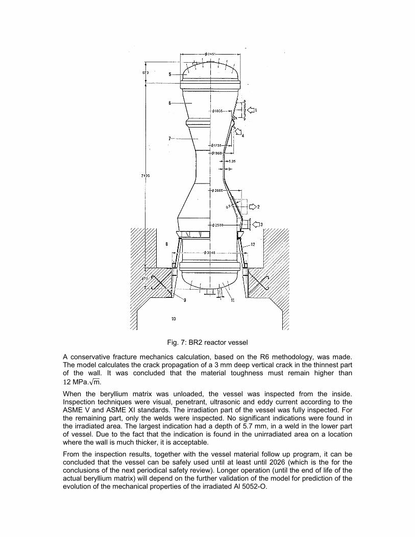
Fig. 7: BR2 reactor vessel
A conservative fracture mechanics calculation, based on the R6 methodology, was made. The model calculates the crack propagation of a 3 mm deep vertical crack in the thinnest part of the wall. It was concluded that the material toughness must remain higher than
12 MPa.√m.
When the beryllium matrix was unloaded, the vessel was inspected from the inside. Inspection techniques were visual, penetrant, ultrasonic and eddy current according to the ASME V and ASME XI standards. The irradiation part of the vessel was fully inspected. For the remaining part, only the welds were inspected. No significant indications were found in the irradiated area. The largest indication had a depth of 5.7 mm, in a weld in the lower part of vessel. Due to the fact that the indication is found in the unirradiated area on a location where the wall is much thicker, it is acceptable.
From the inspection results, together with the vessel material follow up program, it can be concluded that the vessel can be safely used until at least until 2026 (which is the for the conclusions of the next periodical safety review). Longer operation (until the end of life of the actual beryllium matrix) will depend on the further validation of the model for prediction of the evolution of the mechanical properties of the irradiated Al 5052-O.

8 Conclusion
The safety upgrades made during the last years resulted from different occasion (beryllium matrix replacement, periodical safety review, stress tests and new regulation) came in fact all together resulting in one major project. Actual safety standards are followed as good as possible. However, the design of the installation date from 60 years ago and it is not possible to comply with all recent insights. After finishing this project, the reactor can safely operate at least till next periodical safety review.
9 References
[1] “Stress tests” specifications – Proposal by the WENRA Task Force – 21 April 2011 - http://www.wenra.org/.
[2] FANC/AFCN (Federal Agency for Nuclear Control) – Strategic Note: Long Term Operation of Belgium Reactors (text in Dutch or French) - http://www.fanc.fgov.be/
[3] Periodic Safety Review of Nuclear Power Plants, IAEA Safety Guide NS-G.2.10, 2003.
[4] Safe Long Term Operation of Nuclear Power Plants, IAEA Safety Reports Series N° 57, 2008
[5] Website Federal Agency for Nuclear Control (FANC/AFCN): www.fanc.fgov.be (in Dutch or French).
[6] J.R. Licht et al., Steady-State Thermal-Hydraulics Analysis for the Conversion of the BR2 Reactor to LEU, ANL/GTRI/TM-14/8, December 2014.
[7] S. Kalcheva, E. Koonen, A.P. Olson, Development of Refined MCNPX-PARET Multi-Channel Model for Transient Analysis in Research Reactors, PHYSOR 2012, Knoxville, Tennessee, USA, April 15-29, 2012.