the bpm integration in the taiwan photon source
TRANSCRIPT
THE BPM INTEGRATION IN THE TAIWAN PHOTON SOURCE C. H. Kuo, P.C. Chiu, C. Y. Wu, Y. S. Cheng, K. H. Hu, Jenny Chen, Y. T. Chang,
Demi Lee, S. Y. Hsu, K.T. Hsu NSRRC, Hsinchu 30076, Taiwan
Abstract TPS (Taiwan Photon Source) is a 3 GeV synchrotron
light source which is being in construction at NSRRC. The TPS BPM is based on MicroTCA platform, is used for various request and function reasons. These functions will be discussed. Another purpose is for orbit feedback system. The tradition BPM electronic is separated from orbit feedback system, is just monitor. In the TPS, the orbit feedback system is embedded in the BPM crate with FPGA modules. High throughput backplane, data transfer and processing support rich function for waveform recorder, diagnostic, beam study and transient analysis. The implementation result of the BPM system will be reported in this conference.
INTRODUCTION The TPS is a state-of-the-art synchrotron radiation
facility featuring ultra-high photon brightness with extremely low emittance [1]. Civil constructions will be finished in the end of 2013. Machine commissioning is scheduled in 2014. The TPS accelerator complex consists of a 150 MeV S-band linac, linac to booster transfer line (LTB), 0.15 – 3 GeV booster synchrotron, booster to storage ring transfer line (BTS), and 3 GeV storage ring. The storage ring has 24 DBA lattices cells with 6-fold symmetry configuration. This synchrotron machine requires beam position stability less than 1/10 beam size therefore the position measurement system is also required to achieve one hundred or even tens of nanometer resolution. TPS has decided to adopt Libera Brilliance+ [2] electronics for the position measurement. The new instrumentation has the satisfactory performance and diagnostic functionalities as well as provides interface for fast orbit feedback application [3]. The vast tests including current dependency, filling pattern dependency, temperature dependency, and latency estimation, long-term and short-term stability have been done and summarized in this report. Statistics data will be summarized.
TPS BPM The TPS storage ring is divided into 24 cells and there
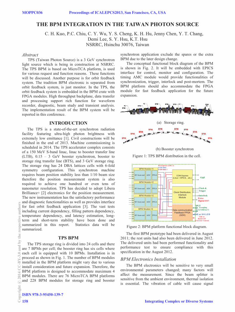
are 7 BPMs per cell; the booster ring has six cells where each cell is equipped with 10 BPMs. Installation is in proceed as shown in Fig. 1. The number of BPM modules installed in the BPM platform might vary due to various install consideration and future expansion. Therefore, the BPM platform is designed to accommodate maximum 4 BPM modules. There are 76 MicroTCA BPM platforms and 228 BPM modules for storage ring and booster
synchrotron application exclude the spares or the extra BPM due to the later design change.
The conceptual functional block diagram of the BPM is shown in Fig. 2. It will be embedded with EPICS interface for control, monitor and configuration. The timing AMC module would provide functionalities of synchronization, trigger, interlock and post-mortem. The BPM platform should also accommodate the FPGA module for fast feedback application for the future expansion.
(a) Storage ring.
(b) Booster synchrotron
Figure 1: TPS BPM distribution in the cell.
COM Express(Linux + EPICS, ..etc.)
Clock Distribution,InterlockModule
PCI Express (AMC.1)LVDS linksLVDS links ?
RF front-end ADC FPGA
BPM Module #1
RF front-end ADC FPGA
BPM Module #2
RF front-end ADC FPGA
BPM Module #4
ExtraDigital I/O?
Data communicationFeedback FPGA
(GDX)
MGT
GigE
Clock &Trigger
Interlock
RF front-end ADC FPGA
BPM Module #2
Grouping(3.2 Gbit/sec?)
GbE or 10 G (UDGbE or
Rocket I/O(Corrector Control)
Figure 2: BPM platform functional block diagram.
The first BPM prototype had been delivered in August 2011; the rest units had also been delivered in June 2012. The delivered units had been performed functionality and performance test to ensure compliance with this specification in the August 2012.
BPM Electronics Installation The BPM electronics will be sensitive to very small
environmental parameters changed; many factors will affect the measurement. Since the beam splitter is sensitive from the ambient environment, thermal isolation is essential. The vibration of cable will cause signal
MOPPC036 Proceedings of ICALEPCS2013, San Francisco, CA, USA
ISBN 978-3-95450-139-7
158Cop
yrig
htc ○
2014
CC
-BY-
3.0
and
byth
ere
spec
tive
auth
ors
Integrating Complex or Diverse Systems

variation as well. Fixed cables are also essential to achieve nano-meter measurement performance. Figure 3 is shown hardware setup for testing temporarily.
Figure 3: All TPS BPM testing in the TLS booster area.
The current dependency, filling pattern dependency, temperature dependency, latency, and short-term and long-term stability are already verified [4].
The BPM electronics provides several data flow including around 10 Hz slow data, 10 kHz fast data, turn by turn data, and ADC raw data. These different data flow resolutions would be estimated respectively as followings.
The TPS have 24 double-bend achromat (DBA) cells, each cell equip with 7 BPMs. Each cell needs two BPM platforms to accommodate 7 BPM modules. There are 48 BPM platforms to accommodate 168 BPM electronics and extra three BPMs at center of three double βy minimum at three long straight sections.
The booster synchrotron have 6 modified FODO cells, each cell equip with 10 BPMs. To simply the cabling, each cell equip with 4 BPM platforms to accommodate 3, 2, 2, 3 BPM modules respectively.
All BPM cable assembly to connect from BPM to BPM
electronics are same length to simply the procurement process and to equal the signal losses. There are 168 sets BPMs for storage ring, cable length is 25 m, each set have 4 cables. Cable length for BPM is installed at the middle of two insertion devices which is 30 m at the long straight section. There are 60 sets for booster ring, cable length is 27 m. BPM platforms number for LTB and BTS are 13 sets in total, all cable length is 28m. Each set of cable assembly are phase matching within 2 at the working frequency of 500MHz. The dielectric material of the coaxial cable is foam polyethylene (PE) with flame retardant halogen-free (LSZH) polyethylene jacket, tinned copper braid, and aluminium tape shield.
In the storage ring of TPS, there are four 0.195” foam PE dielectric, 1.2 m long phase matched radiation resistant cable assembly is connected to BPM buttons with 25 m long PE coaxial cables. In the BTS LTB and booster, there are four 0.200” foam PE dielectric, phase matched 0.55 m long cable assembly is connected to the BPM buttons with 27/28 m long cable from BPM electronics.
To accommodate fast orbit feedback, all 48 BPM
platforms for the storage ring are grouping together. The grouping is handled by the FPGA modules on the BPM platform via multi-gigabits link. BPM platforms at same cell are connected via a SFP+ copper cable. Link to another cells are connected via OM3 fibre link. Bit rate of grouping is working at 6.25 Gbps. Data can reach to all platforms within 16 μsec. Fast orbit feedback loop will working at 10 KHz rate. Feedback computation is require about 2 μsec. Corrector setting need about 2 μsec. Communication latency is much less than the sampling period.
For the fast orbit feedback request, it will execute on
the same FPGA module of BPM grouping. One SFP interface of the FPGA module is responsible to link to the corrector power supply control module (CPSC), which controls 4 horizontal and 4 vertical corrector power supplies at each cell.
To support 24/7/365 operation of the BPM electronics,
functionalities like cold start, shutdown, housekeeping, control system interface should meet all of these requirements.
Figure 4: GUI main page for TPS.
The EPICS interfaces for all BPM platforms are tested.
One defect is that some waveform records are empty (data is zeros) for first acquisition even external trigger is given. Besides, EPICS CA server crash had occasionally occurred and was reported to the vender. There is no this problem that the currency software version after upgrade.
The BPM platform provides power supply status
Proceedings of ICALEPCS2013, San Francisco, CA, USA MOPPC036
Integrating Complex or Diverse Systems
ISBN 978-3-95450-139-7
159 Cop
yrig
htc ○
2014
CC
-BY-
3.0
and
byth
ere
spec
tive
auth
ors

monitoring, temperature monitoring, fan status monitoring and fan control. The status looks good from the system maintenance point of view.
(a)
(b)
Figure 5: BPM configuration control page (a)(b).
The GUI (graphic user interface) for BPM operation,
configuration and management based on EDM and Matlab had been continuously developed. The BPM page can be launched from the TPS main control page as shown in the fig.4.
Figure 5 shows BPM configuration, setup and maintenance control page for installation, setup and device diagnostic.
The BPM main display page is shown as Fig. 6 which shows the part of DC orbit for the storage ring and Fig. 7 shows the ramping orbit of the booster during injection respectively. It also could launch many necessary functions such as the configuration management which
requires the authority, axes adjustment, absolute/different orbit selection, signal trend, data saving and etc.
Figure 6: The storage ring DC orbit display page.
Figure 7: Booster 10kHz ramping trend. Several units are only tested in the TLS booster.
High Level Application Interface The waveform display GUI is also provided to aim for
simple trouble shooting as Fig. 8. The upper plot shows the ADC raw data and the lower plot is turn by turn data where the signal source is now temporarily connected to TLS booster. Through them, it could check basic BPM connection, signal integrity, phase difference and etc. Besides, the further signal analysis and processing will be based on the other specific application programs.
MOPPC036 Proceedings of ICALEPCS2013, San Francisco, CA, USA
ISBN 978-3-95450-139-7
160Cop
yrig
htc ○
2014
CC
-BY-
3.0
and
byth
ere
spec
tive
auth
ors
Integrating Complex or Diverse Systems

(b)
Figure 8: (a) BPM ADC data (b) BPM turn by turn data. The signal source is now temporarily connected to TLS booster.
These high level application GUIs are developed by MATLAB toolkit, to satisfy with various complicated calculation.
TPS BPM electronics preliminary testing has been finished in the early of this year. Each BPM platform and module had been individually tested and measured. Fundamental functionalities are passed. SA, FA and TBT resolution generally satisfy specification. The software operation environment and integration is going on development, to catch up the real location hardware commission in the first quarter of next year. Current, filling pattern and temperature dependency are also adequate. Mechanic stability is key issue beyond expectation when it requires nano-meter level stability. All testing will be based on the GUI for operation. The software modification is still continuous. The CSS software toolkit for BPM will be used between cross platforms operation request. BPM system installation and hardware is scheduled in early 2014. Integrated test with corrector power supply will be possible the 2nd quarter of 2014.
The authors appreciate help from staffs of I-Tech for brainstorming and discussion.
[1] TPS Design Handbook, version 16, June 2009. [2] Instrumentation Technologies: http://www.i-tech.si. [3] GDX Module Specifications v1.1. [4] P. C. Chiu, et al., TPS BPM electronics performance
measurement and statistics”, Proceedings of IBIC2012.
(a)
Proceedings of ICALEPCS2013, San Francisco, CA, USA MOPPC036
Integrating Complex or Diverse Systems
ISBN 978-3-95450-139-7
161 Cop
yrig
htc ○
2014
CC
-BY-
3.0
and
byth
ere
spec
tive
auth
ors