the board of education breadboard, pbasic, and servosmars.umhb.edu/~prg/engr1310/pbasic.pdfvss) to...
TRANSCRIPT
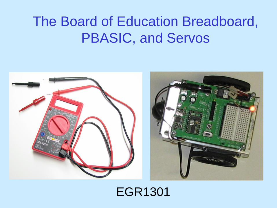
The Board of Education Breadboard,
PBASIC, and Servos
EGR1301
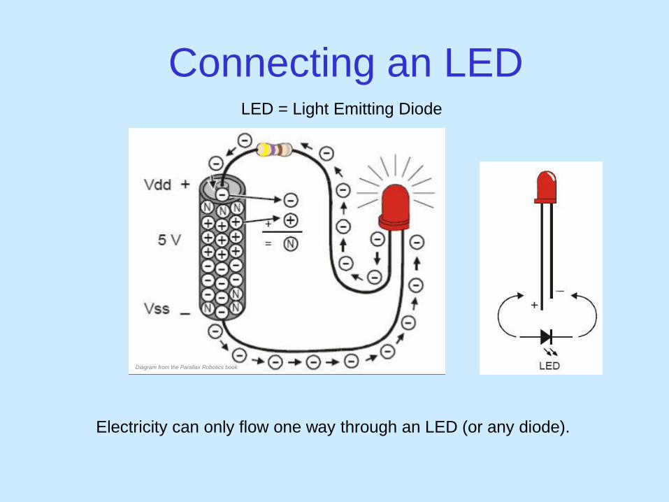
Connecting an LED
Electricity can only flow one way through an LED (or any diode).
LED = Light Emitting Diode
Diagram from the Parallax Robotics book
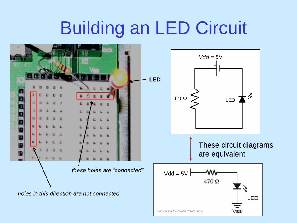
Building an LED Circuit
Vdd = 5V
LED
5V
+ -
470W
These circuit diagrams
are equivalent
these holes are “connected”
Vdd =
LED
holes in this direction are not connected
Diagram from the Parallax Robotics book

Replace the 470W Resistor
with the 10kW Resistor
What happens and Why??
ANSWER: The smaller resistor (470W) provides less resistance to current than
the larger resistor (10kW). Since more current passes through the smaller
resistor, more current also passes through the LED making it brighter.
What would happen if you forgot to put in a resistor?
You would probably burn up your LED.
www.radgraphics.net
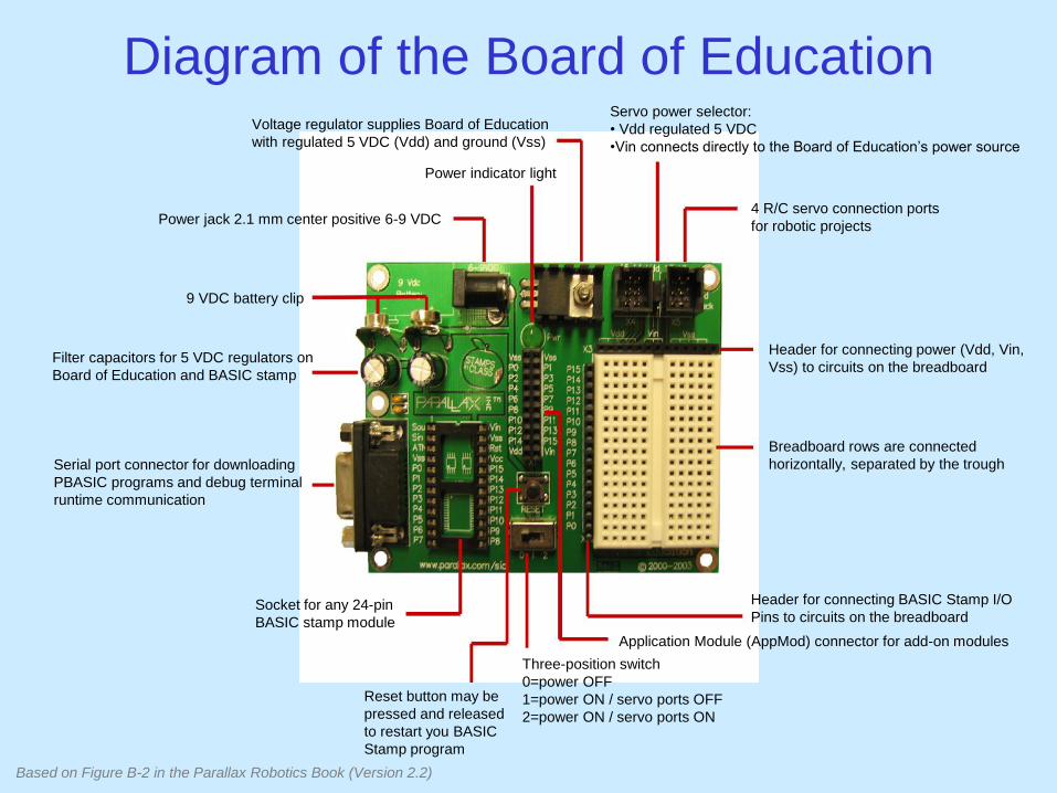
Voltage regulator supplies Board of Education
with regulated 5 VDC (Vdd) and ground (Vss)
Servo power selector:
• Vdd regulated 5 VDC
•Vin connects directly to the Board of Education’s power source
Header for connecting power (Vdd, Vin,
Vss) to circuits on the breadboard
4 R/C servo connection ports
for robotic projects
Header for connecting BASIC Stamp I/O
Pins to circuits on the breadboard
Breadboard rows are connected
horizontally, separated by the trough
Application Module (AppMod) connector for add-on modules
Power indicator light
Power jack 2.1 mm center positive 6-9 VDC
Three-position switch
0=power OFF
1=power ON / servo ports OFF
2=power ON / servo ports ON
Filter capacitors for 5 VDC regulators on
Board of Education and BASIC stamp
Serial port connector for downloading
PBASIC programs and debug terminal
runtime communication
Socket for any 24-pin
BASIC stamp module
Reset button may be
pressed and released
to restart you BASIC
Stamp program
9 VDC battery clip
Diagram of the Board of Education
Based on Figure B-2 in the Parallax Robotics Book (Version 2.2)
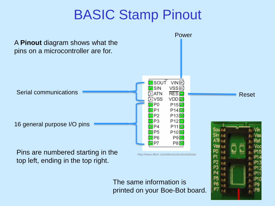
BASIC Stamp Pinout
16 general purpose I/O pins
Serial communications
Power
Reset
A Pinout diagram shows what the
pins on a microcontroller are for.
Pins are numbered starting in the
top left, ending in the top right.
The same information is
printed on your Boe-Bot board.
http://www.dlwrr.com/electronics/tools/bsla/
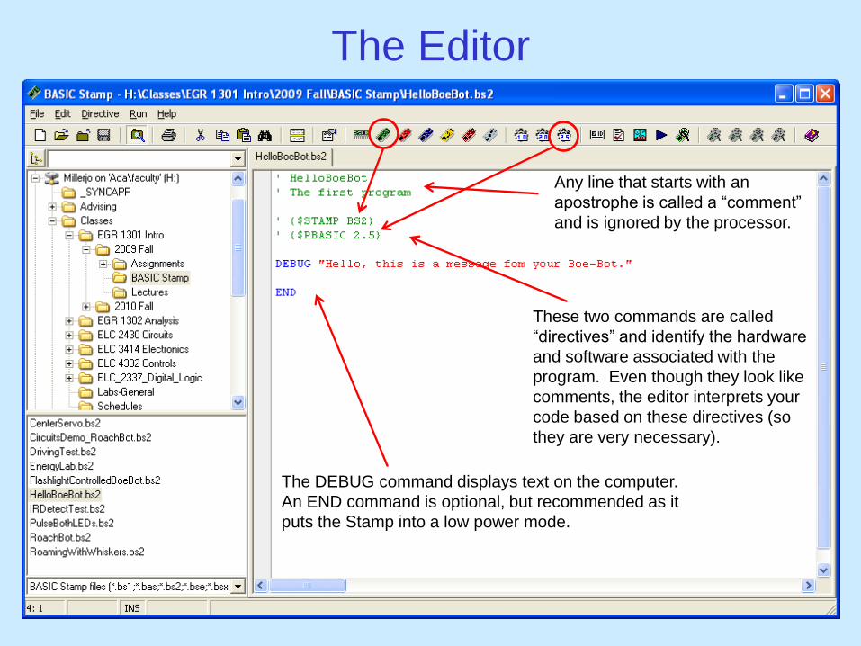
The Editor
Any line that starts with an
apostrophe is called a “comment”
and is ignored by the processor.
These two commands are called
“directives” and identify the hardware
and software associated with the
program. Even though they look like
comments, the editor interprets your
code based on these directives (so
they are very necessary).
The DEBUG command displays text on the computer.
An END command is optional, but recommended as it
puts the Stamp into a low power mode.
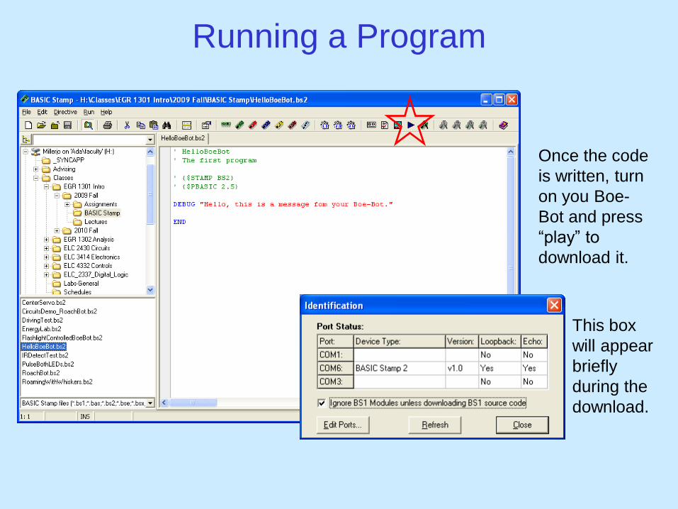
Running a Program
Once the code
is written, turn
on you Boe-
Bot and press
“play” to
download it.
This box
will appear
briefly
during the
download.

Connect the Resistor to Pin 12 (P12)
' {$STAMP BS2} ' {$PBASIC 2.5} DO HIGH 12 PAUSE 500 LOW 12 PAUSE 500 LOOP
Enter and run the following PBASIC program:
Diagram from the Parallax Robotics book

Causes pin 12 to output a constant 5V (Vdd)
' {$STAMP BS2} ' {$PBASIC 2.5} DO HIGH 12 PAUSE 500 LOW 12 PAUSE 500 LOOP
How the Program Works
infinite loop
Causes pin 12 to output a constant 0V (Vss)
wait 500 ms
Wait 500 ms
Diagram from the
Parallax Robotics book
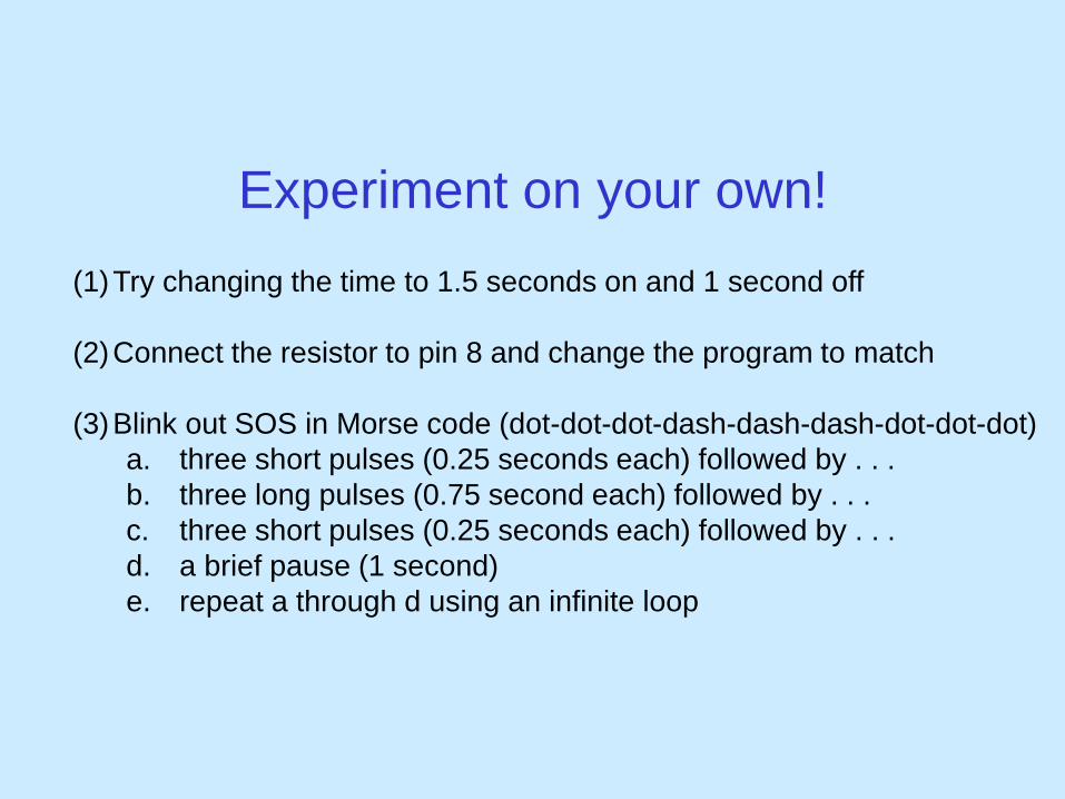
Experiment on your own!
(1)Try changing the time to 1.5 seconds on and 1 second off
(2)Connect the resistor to pin 8 and change the program to match
(3)Blink out SOS in Morse code (dot-dot-dot-dash-dash-dash-dot-dot-dot)
a. three short pulses (0.25 seconds each) followed by . . .
b. three long pulses (0.75 second each) followed by . . .
c. three short pulses (0.25 seconds each) followed by . . .
d. a brief pause (1 second)
e. repeat a through d using an infinite loop

' {$STAMP BS2} ' {$PBASIC 2.5} DO PULSOUT 12, 65000 PAUSE 2000 LOOP
Enter and run the following PBASIC program:
Another Way to Make the LED Blink
Causes pin 12 to output a constant 5V for . . .
65000 x 2ms = 130000 ms = 0.13 s Wait 2000 ms = 2 s
Diagram from the Parallax Robotics book
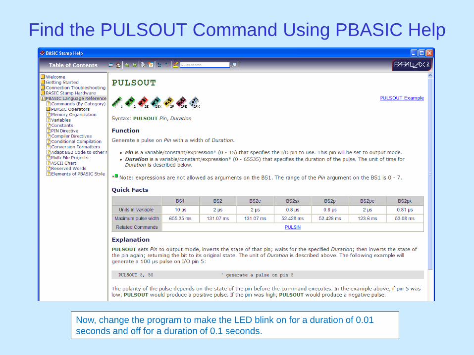
Find the PULSOUT Command Using PBASIC Help
Now, change the program to make the LED blink on for a duration of 0.01
seconds and off for a duration of 0.1 seconds.
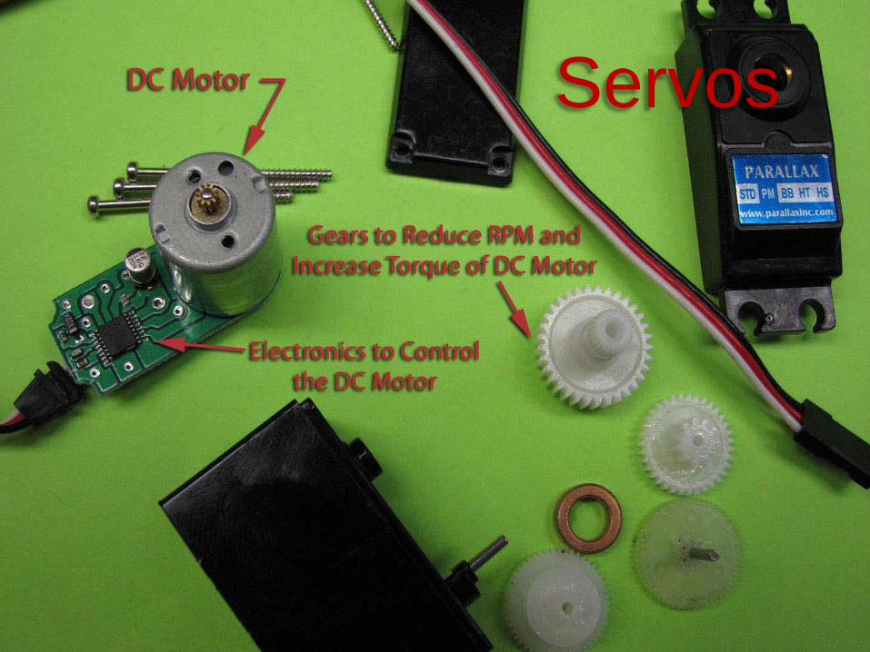
Servos
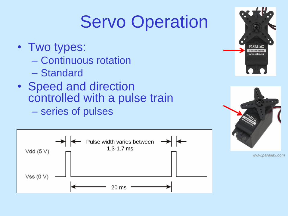
Servo Operation
• Two types: – Continuous rotation
– Standard
• Speed and direction controlled with a pulse train – series of pulses
20 ms
Pulse width varies between
1.3-1.7 ms www.parallax.com

Duration Pulse Width (ms) Servo Action
650 1.3 Full speed CW
700 1.4 ~1/2 speed CW
750 1.5 Stopped
800 1.6 ~1/2 speed CCW
850 1.7 Full speed CCW
Pulse Width vs. Speed Table
Note 1: Speed is NOT linear with pulse duration.
Note 2: To move your Boe-Bot in one direction (either forward or
backward), the servos will have to rotate in opposite directions (i.e. one
CW, the other CCW).
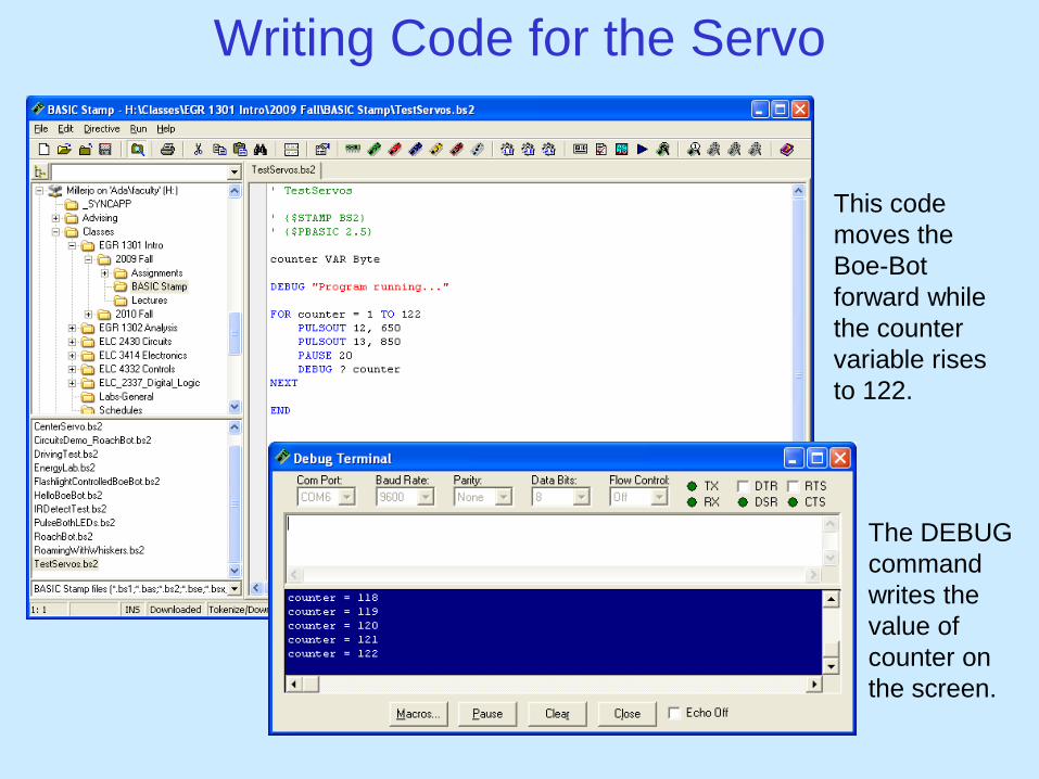
Writing Code for the Servo
This code
moves the
Boe-Bot
forward while
the counter
variable rises
to 122.
The DEBUG
command
writes the
value of
counter on
the screen.
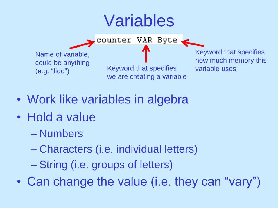
Variables
• Work like variables in algebra
• Hold a value
– Numbers
– Characters (i.e. individual letters)
– String (i.e. groups of letters)
• Can change the value (i.e. they can “vary”)
Name of variable,
could be anything
(e.g. “fido”) Keyword that specifies
we are creating a variable
Keyword that specifies
how much memory this
variable uses
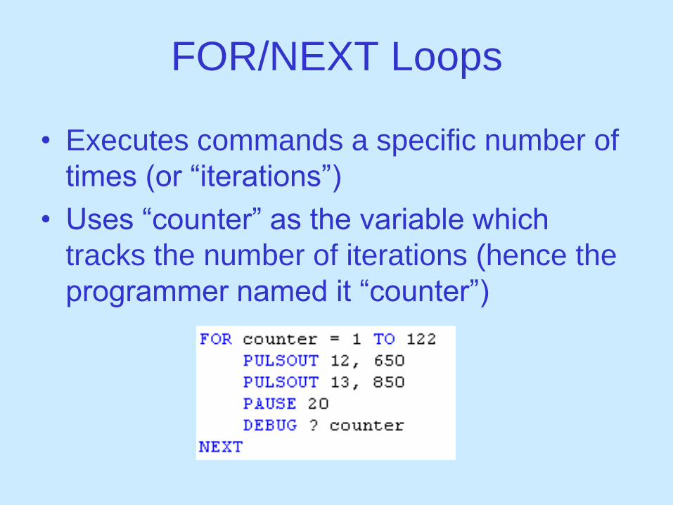
FOR/NEXT Loops
• Executes commands a specific number of
times (or “iterations”)
• Uses “counter” as the variable which
tracks the number of iterations (hence the
programmer named it “counter”)
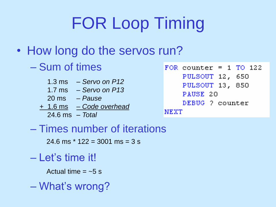
FOR Loop Timing
• How long do the servos run?
– Sum of times
– Times number of iterations
– Let’s time it!
– What’s wrong?
1.3 ms
1.7 ms
20 ms
+ 1.6 ms
24.6 ms
– Servo on P12
– Servo on P13
– Pause
– Code overhead
– Total
24.6 ms * 122 = 3001 ms = 3 s
Actual time = ~5 s

FOR Loop Timing Cont.
• What is “Code overhead”?
– Amount of time required for the processor to
execute the commands, which includes:
• incrementing the counter variable
• sending messages to the Debug Terminal
• other things
• Remove the DEBUG command
– Could also “comment out”
• Now lets time it! Actual time = ~3 s

PBASIC Commands Used
• DEBUG – prints to the Debug Terminal on the computer
• END – puts the BASIC Stamp in a low power state
• HIGH & LOW – sets a pin to either +5 V or 0 V
• PAUSE – temporarily suspends execution
• DO/LOOP – executes statements in an infinite loop
• PULSOUT – pulses a pin for a specific amount of time
• FOR/NEXT – executes statements for a specific number of
iterations
• VAR – creates a variable that can be used in the program

Programming Tips
• Use comments!
• Use variable names that mean something
(e.g. “counter”, “Lspeed”)
– But don’t use other keywords (e.g. HIGH, END)
• Use Help to learn syntax
End of Lecture…
BUT
Experiment with your Boe-Bot,
Make it go forward, backward, turn
corners, drive in a square, etc…