the avengers measuring atmospheric ozone gases. general the primary goal of the ito sensor project...
TRANSCRIPT
THE THE AVENGERSAVENGERSMeasuring Atmospheric Measuring Atmospheric
Ozone gasesOzone gases
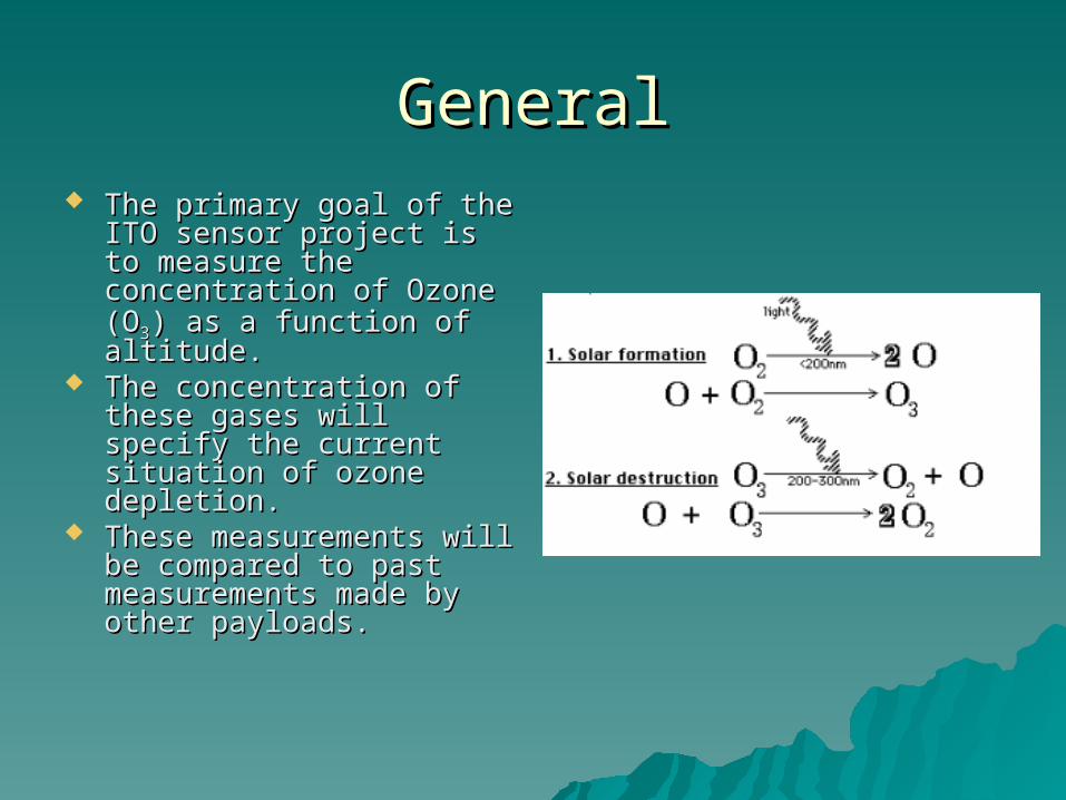
GeneralGeneral The primary goal of the ITO The primary goal of the ITO
sensor project is to sensor project is to measure the concentration measure the concentration of Ozone (Oof Ozone (O33) as a function ) as a function of altitude. of altitude.
The concentration of these The concentration of these gases will specify the gases will specify the current situation of ozone current situation of ozone depletion.depletion.
These measurements will These measurements will be compared to past be compared to past measurements made by measurements made by other payloads.other payloads.

ScienceScience The ozone layer is the layer in The ozone layer is the layer in
Earth’s atmosphere which contains Earth’s atmosphere which contains relatively high concentrations of relatively high concentrations of ozone. This layer contains over ozone. This layer contains over 91% of the ozone in Earth’s 91% of the ozone in Earth’s atmosphere. It is mainly located in atmosphere. It is mainly located in the lower portion of the the lower portion of the stratosphere, from approximately stratosphere, from approximately 10 km to 50 km above Earth10 km to 50 km above Earth..
Halogens, the chemical family Halogens, the chemical family containing fluorine, chlorine, containing fluorine, chlorine, bromine, and iodine, have thbromine, and iodine, have the e ability to catalyze ability to catalyze oozonezone bbreakdown.reakdown.
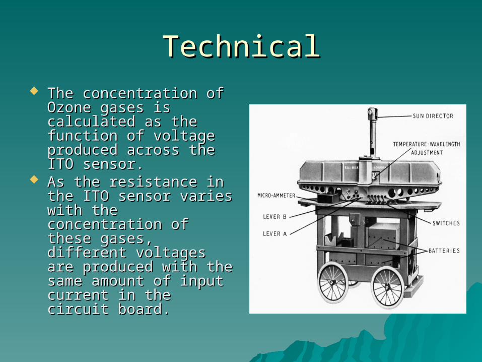
TechnicalTechnical The concentration of The concentration of
Ozone gases is Ozone gases is calculated as the calculated as the function of voltage function of voltage produced across the ITO produced across the ITO sensor.sensor.
As the resistance in the As the resistance in the ITO sensor varies with ITO sensor varies with the concentration of the concentration of these gases, different these gases, different voltages are produced voltages are produced with the same amount of with the same amount of input current in the input current in the circuit board.circuit board.
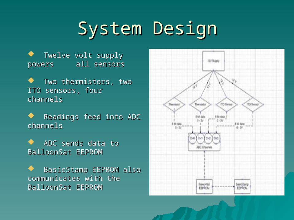
System DesignSystem Design Twelve volt supply powers Twelve volt supply powers all sensors all sensors
Two thermistors, two ITO Two thermistors, two ITO sensors, four channelssensors, four channels
Readings feed into ADC Readings feed into ADC channelschannels
ADC sends data to ADC sends data to BalloonSat EEPROMBalloonSat EEPROM
BasicStamp EEPROM also BasicStamp EEPROM also communicates with the communicates with the BalloonSat EEPROMBalloonSat EEPROM
Electrical Design and Electrical Design and DevelopmentDevelopment
Sensors/Sensor InterfacingSensors/Sensor InterfacingControl ElectronicsControl Electronics
Power SupplyPower SupplyPower BudgetPower Budget
Electrical Development PlanElectrical Development Plan

SensorsSensors
ITOITO
Measures Ozone based on resistance Measures Ozone based on resistance across the sensor.across the sensor.
As ozone increases, resistance increases.As ozone increases, resistance increases.
Provided by Dr. Patel of the University of Provided by Dr. Patel of the University of North FloridaNorth Florida
THERMISTORSTHERMISTORS
Two 1k Ohm thermistors. Two 1k Ohm thermistors.
Measures temperature based off the Measures temperature based off the resistance across the thermistor. resistance across the thermistor.
As temperature decreases, resistance As temperature decreases, resistance increases.increases.
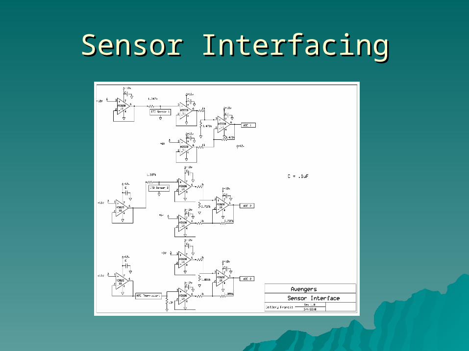
Sensor InterfacingSensor Interfacing

Control ElectronicsControl Electronics

Power SupplyPower Supply

Power BudgetPower Budget

Software DesignSoftware Design
Data Format and StorageData Format and Storage
Flight SoftwareFlight Software
Software Development PlanSoftware Development Plan

Data Format and StorageData Format and Storage
BalloonSat EEPROM BalloonSat EEPROM will store all data will store all data collected on flight collected on flight (Yellow Circle)(Yellow Circle)
BasicStamp EEPROM BasicStamp EEPROM stores addresses for stores addresses for flight software (Red flight software (Red Circle)Circle)
0 Counter N/A1 Hour N/A2 Minute N/A3 Second N/A4 ITO Sensor 1 15 ITO Sensor 2 26 Thermistor 1 07 Thermistor 2 3
Byte # Data Stored0 Original Address1 Current Address

Flight SoftwareFlight Software Read “original address” from Read “original address” from
BasicStamp EEPROMBasicStamp EEPROM Add counter to data Add counter to data
– 1 byte1 byte Read RTC Read RTC
– 3 bytes3 bytes Read both thermistors and Read both thermistors and
both ITO sensorsboth ITO sensors– 4 bytes4 bytes
Store all data from reading Store all data from reading Store current address in Store current address in
BasicStamp EEPROMBasicStamp EEPROM Repeat loop until current Repeat loop until current
address equals the original address equals the original addressaddress– ((current_address = current_address =
original_address)original_address)– LED flashes once per secondLED flashes once per second

Software Development PlanSoftware Development Plan Prototyping SoftwarePrototyping Software
– Software must run without Software must run without glitchesglitches
– Software must successfully Software must successfully record correct data from input record correct data from input sensorssensors
Data must be saved in a Data must be saved in a way that it will not be way that it will not be overwrittenoverwritten
– Once software is completely Once software is completely functional, it will be optimizedfunctional, it will be optimized
– Software will be uploaded to Software will be uploaded to Excel, so it must be formattedExcel, so it must be formatted
Prototyping HardwarePrototyping Hardware – Electronics and Mechanical Electronics and Mechanical
aspects should work with aspects should work with softwaresoftware
– Temperature and Pressure TestsTemperature and Pressure Tests FlowchartsFlowcharts
– As the code is written and As the code is written and refined, flowcharts will be refined, flowcharts will be updatedupdated

Mechanical DesignMechanical DesignA hollow regular A hollow regular hexagonal prismhexagonal prismFOAMULAR Insulating FOAMULAR Insulating SheathingSheathing
External Design:External Design:Each side of the base Each side of the base = 94 mm= 94 mmThe height of the The height of the prism = 175 mmprism = 175 mm51mm X 49mm 51mm X 49mm rectangular hole for the rectangular hole for the ITO sensorITO sensorThe ITO sensor The ITO sensor attached from the inner attached from the inner walls; minimal area of walls; minimal area of the ITO sensor is the ITO sensor is exposedexposed
The external design of ITO sensor payload (in mm)
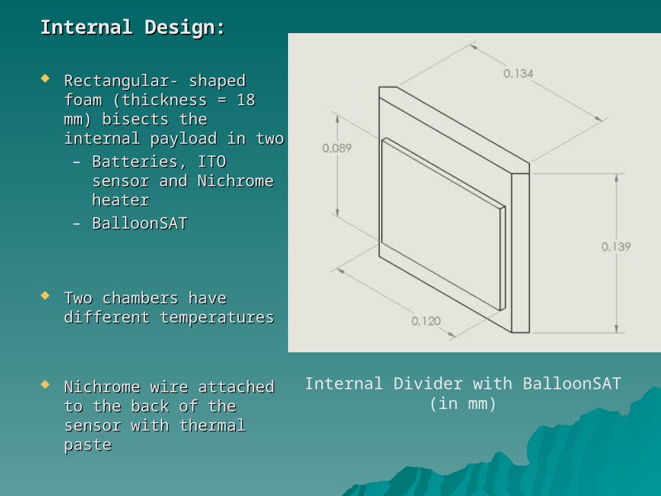
Internal Design:Internal Design:
Rectangular- shaped foam Rectangular- shaped foam (thickness = 18 mm) (thickness = 18 mm) bisects the internal bisects the internal payload in twopayload in two– Batteries, ITO sensor Batteries, ITO sensor
and Nichrome heaterand Nichrome heater– BalloonSATBalloonSAT
Two chambers have Two chambers have different temperaturesdifferent temperatures
Nichrome wire attached to Nichrome wire attached to the back of the sensor the back of the sensor with thermal pastewith thermal paste
Internal Divider with BalloonSAT (in mm)
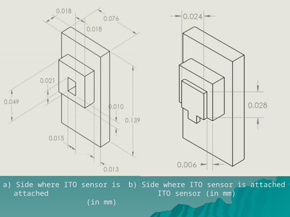
a) Side where ITO sensor is attached (in mm)
b) Side where ITO sensor is attached with ITO sensor (in mm)

Weight Budget:Weight Budget:
Balloon payload should be less that 500 gBalloon payload should be less that 500 g Density of The FOAMULAR Insulating Sheathing = .029 g/ cmDensity of The FOAMULAR Insulating Sheathing = .029 g/ cm33
S.S.N. N.
Components Components Weight (gram) Weight (gram) Clearance (g) Clearance (g)
1.1. BalloonSATBalloonSAT 60.460.4 +/- 10 +/- 10
2.2. FOAMULAR Insulating FOAMULAR Insulating Sheathing Sheathing
115115 +/- 20 +/- 20
3.3. Power Supply (Battery) Power Supply (Battery) 121.9121.9 +/- 25 +/- 25
4.4. ITO sensor and PCB ITO sensor and PCB 6.16.1 +/- 2+/- 2
5.5. Components for Sensor Components for Sensor Interface Interface
3535 +/- 15 +/- 15
6.6. Mass of cable for ITO Mass of cable for ITO sensorsensor
1717 +/- 3+/- 3
Total:Total: 355.4355.4 +/- 75+/- 75
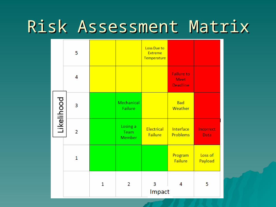
Risk Assessment MatrixRisk Assessment Matrix
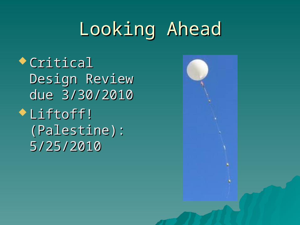
Looking AheadLooking Ahead
Critical Design Critical Design Review due Review due 3/30/20103/30/2010
Liftoff! Liftoff! (Palestine): (Palestine): 5/25/20105/25/2010

Special ThanksSpecial Thanks
Dr. Nirmalkumar PatelDr. Nirmalkumar Patel