the arubas create a pleasant indoor climate - est … · the arubas create a pleasant indoor...
TRANSCRIPT

www.weinor.co.uk
The Arubas create a pleasant indoor climate
Aruba Carré/Round
Aruba Carré/Round 1
We
rese
rve
the
right
to
mak
e te
chni
cal a
ltera
tions
. Dec
embe
r 20
06
Windowawnings ArubaCarré/Round/Vertical/Droparm/Markisolette
Aruba Carré/Round
Aruba Carré/Round 2
We
rese
rve
the
right
to
mak
e te
chni
cal a
ltera
tions
. Dec
embe
r 20
06
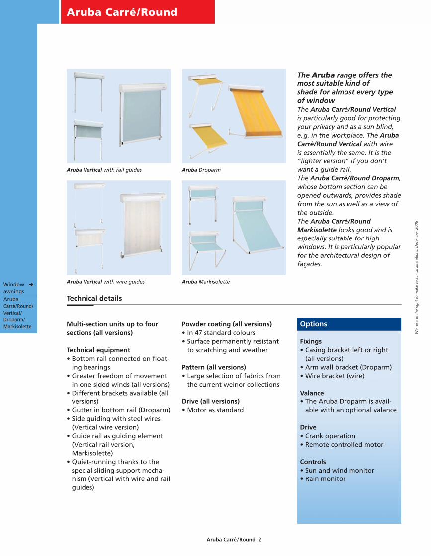
The Aruba range offers themost suitable kind of shade for almost every typeof windowThe Aruba Carré/Round Verticalis particularly good for protectingyour privacy and as a sun blind,e.g. in the workplace. The ArubaCarré/Round Vertical with wire is essentially the same. It is the“lighter version” if you don’twant a guide rail.The Aruba Carré/Round Droparm,whose bottom section can beopened outwards, provides shadefrom the sun as well as a view ofthe outside. The Aruba Carré/RoundMarkisolette looks good and isespecially suitable for highwindows. It is particularly popularfor the architectural design offaçades.
Multi-section units up to foursections (all versions)
Technical equipment• Bottom rail connected on float-
ing bearings• Greater freedom of movement
in one-sided winds (all versions)• Different brackets available (all
versions)• Gutter in bottom rail (Droparm)• Side guiding with steel wires
(Vertical wire version)• Guide rail as guiding element
(Vertical rail version,Markisolette)
• Quiet-running thanks to thespecial sliding support mecha-nism (Vertical with wire and railguides)
Powder coating (all versions)• In 47 standard colours• Surface permanently resistant
to scratching and weather
Pattern (all versions)• Large selection of fabrics from
the current weinor collections
Drive (all versions)• Motor as standard
Options
Fixings• Casing bracket left or right
(all versions)• Arm wall bracket (Droparm)• Wire bracket (wire)
Valance• The Aruba Droparm is avail-
able with an optional valance
Drive• Crank operation• Remote controlled motor
Controls• Sun and wind monitor• Rain monitor
Technical details
Aruba Vertical with rail guides Aruba Droparm
Aruba MarkisoletteWindow ➔
awnings Aruba Carré/Round/Vertical/Droparm/Markisolette
Aruba Vertical with wire guides

Aruba Carré/Round Vertical
Aruba Carré/Round 3
We
rese
rve
the
right
to
mak
e te
chni
cal a
ltera
tions
. Dec
embe
r 20
06
The sliding support mechanismThe special sliding support mech-anism ensures quieter and safeoperation.
Aruba Carré Vertical open … … half open … … and retracted.
The technical product highlights of the Aruba Carré/Round Vertical with rail guides
The faceplateThe Aruba Vertical with railguides comes with a faceplate onthe box.
The couplingUp to four sections of the ArubaVertical with rail guides can becoupled.
Sliding support mechanism
The floating bearing bottom railconnectionThis prevents tilting in highwinds.

Aruba Carré/Round Vertical
Aruba Carré/Round 4
We
rese
rve
the
right
to
mak
e te
chni
cal a
ltera
tions
. Dec
embe
r 20
06Stainless steel guide boltIt goes without saying that thebolt the wire goes through is ofstainless steel, and the bottomrail with floating bearing allowsenough “play”, e.g. in highwinds: no tilting, safe and cleanrunning.
… half open …
Stainless steel bolt in bottom rail and
simple wire tensioner on the wire bracket
… and retracted.
The technical product highlights of the Aruba Carré/Round Vertical with wire guides
Aruba Carré Vertical wire version open …
The wire bracketThe various wire brackets aredesigned for all normal fittingsituations.
The windowsill wire bracket canbe screwed on to a windowsill,for example.The small wire bracket is popularfor firm metal surfaces.The large wire bracket is suppliedas standard and the distancebetween the holes is great, whichmakes it suitable for suchlocations as brickwork.
Windowsill
wire bracket
Small wire
bracket
Large wire
bracket
The faceplateThe Aruba Vertical with railguides comes with a faceplate on the box.
The couplingUp to four sections of the ArubaVertical with wire guides can becoupled.It is essential that all surfaces
are checked for their stability andstrength before attachingbrackets to them.
Side-mounted guide elements ofstainless steel wireWith essentially the same func-tions as the Aruba Vertical withrail guides, it is the visually“lighter” alternative. Considera-tions when fitting can make thewire version the right choice forthe window.
The weinor tensionerWhat makes it so special: afterbeing tensioned in situ, theweinor tensioner makes sure thewire remains taut:• The wire does not sag after
fitting or from stretching.• The tensioner is in the cassette
and protected from theelements.

Aruba Carré/Round Droparm
Aruba Carré/Round 5
We
rese
rve
the
right
to
mak
e te
chni
cal a
ltera
tions
. Dec
embe
r 20
06
The technical product highlights of the Aruba Carré/Round Droparm
… half open … … and retracted.Aruba Carré Droparm open …
Arm angled at 150°
The bottom railThe bottom rail with enforcedclosing mechanism closes flushwith the casing. The fabricremains protected in the casing.
The couplingUp to four sections of the ArubaDroparm can be coupled.
Bottom rail connected on floating
bearings
Optional valanceThe Aruba Droparm is availablewith an optional valance.
Aruba Droparm with valance
The rotating bottom railconnectionThis reduces tilting in high winds.
The droparmsThe variable droparms with internalsprings allow the arms to turn to amaximum angle of 150°.

Aruba Carré/Round Markisolette
Aruba Carré/Round 6
We
rese
rve
the
right
to
mak
e te
chni
cal a
ltera
tions
. Dec
embe
r 20
06
… half open, the arms automatically
swing outwards …
… vertical fabric, and retracted.
The technical product highlights of the Aruba Carré/Round Markisolette
Aruba Carré/Round Markisolette
open …
The arm link on floating bearingsThis prevents tilting in highwinds.
Arms with internal
springs
Arm angled at 150°On floating bearings
The lock safety deviceIt prevents the arm mechanismfrom being lifted up.
Once the arm has opened a little the lock
safety device clicks in. The point at which
it turns can be adjusted.
The couplingUp to four sections of the ArubaMarkisolette can be coupled.
The faceplateThe Aruba Markisolette has afaceplate on the casing.
The armsThe arms with internal springsallow the Aruba Markisoletteto be angled at up to a maximumof 150°.

Aruba Carré/Round – all versions
Aruba Carré/Round 7
We
rese
rve
the
right
to
mak
e te
chni
cal a
ltera
tions
. Dec
embe
r 20
06 Crank operated driveThe drive with offset handle lead-ing inside with an offset handle(90°). This makes it possible tooperate from the inside (only onsingle-section units).
Multi-section unitsWhat is important with multi-section units is that they worksafely and that the sections canbe coupled easily. Multi-sectionunits are fitted with a motordrive as standard.
The weinor drive shaft is connected with
a fork and pin system
Applicable to all versions
This view can only be seen during assembly. Afterwards, only solid and fault-free operation count.
The shape of the casingThe classic angular shape of theAruba Carré or the roundedshape of the Aruba Round? It’spurely a matter of taste.
Aruba Carré Aruba Round
The look of the casingAll Aruba casings look the same,which makes them ideal forjoining.
It goes without saying that theyare easy to service and fit.

Product benefits at a glance
Designation Material Surface
treatment
Qualities Your advantages
Aruba Carré/Round
Aruba Carré/Round 8
We
rese
rve
the
right
to
mak
e te
chni
cal a
ltera
tions
. Dec
embe
r 20
06
Casing in faceplate Aluminium,
extruded
Chrome-free
passivised,
powder coated
Easy access for servicing.
Roller in guide section Stainless steel
Plastic
Non-corrosive The Aruba opens and retracts safely.
Drive motor Precisely manufac-
tured robust design
Easy operation as standard. Optionally
with remote controlled motor and
remote control unit.
See the Accessories section for details.
Prevents the arm mechanism from being
lifted up.
Screws and
connectors
Stainless steel
Non-corrosive
No rust, no appreciable wear and tear
Support brackets
Fixing brackets
Cast aluminium Chrome-free
passivised,
powder coated
Rust protection, down to the last detail
with pre-treatment and powder coating.
Droparm lock
(Aruba Markisolette)
Plastic
Casing section
Bottom rail
Guide section
Support bar
Aluminium,
extruded
You choose the powder coating colour
for your Aruba Carré/Round sections to
suit your house or conservatory.
Pre-treating the profiles prevents
corrosion altogether, even on damaged
surfaces.
Chrome-free
passivised,
powder coated
Awning material Acrylic Spin-jet dyed,
impregnated
Light-fast and
weatherproof
The weinor fabric collection offers a
wide variety of sophisticated patterns
for the Aruba Carré/Round.
Surface permanently
resistant to scratch-
ing and weather
Surface permanently
resistant to scratch-
ing and weather
Non-corrosive

Overview of product options
Designation Material Surface
treatment
Qualities Your advantages
Aruba Carré/Round
Aruba Carré/Round 9
We
rese
rve
the
right
to
mak
e te
chni
cal a
ltera
tions
. Dec
embe
r 20
06
Drive crank mechanism
with limit stop
Gearing
6:1
Gears with
limit stop,
easy to operate
Completely free from operating error.
The limit stop prevents the fabric from
rolling up incorrectly.
Remote-controlled
drive
Upon request, an integrated tubular
motor with WeiTronic receiver can be
fitted. The WeiTronic Remoto handheld
remote control makes for easy operation
of the awning.
See the Accessories section for more
details.
Fixings
Standard and
special versions
Aluminium,
extruded,
sections cut and
machined
Machine-edged,
chrome-free
pre-treated,
powder coated
Surface permanently
resistant to scratch-
ing and weather
Sophisticated quality, precise and
weather resistant down to the very last
detail. Using identical components
makes maintenance easier.
Awning fabric from
external suppliers
Acrylic Spin-jet dyed,
impregnated
Special coated
polyester fibre
Warp printed
watertight
Micro-vented,
light permeable
Even greater selection of unicolour and
striped fabrics.
Is suitable when the shade has to be
more light and air permeable than
acrylic.
Soltis

Aruba Carré/Round Vertical
Aruba Carré/Round 10
We
rese
rve
the
right
to
mak
e te
chni
cal a
ltera
tions
. Dec
embe
r 20
06
Exploded drawing of the Aruba Carré Vertical with rail guides
Soffit elbow, wide
Soffit elbow, narrow
Additional adaptor, left
End plate, left
Soffit elbow, small
Fabric roller with fabricand fabric roller insert
Box bracket, left
Top fixing
Soffit elbow of box bracket
Box bracket, right
Additional adaptor, right
End plate, right
Drive side adaptor
414 FMS gears
Box section
Cover profile
Guide sectionBearing sideadaptor
Bottom rail holder
Bottom rail insert
Bottom rail
Drive adaptor coupling
Motor
Box bracket, left
Mounting plate box bracket coupling
AdaptorAdaptor
Box bracket, right
End plate, right coupling
Square fork
Fabric roller insert
Fabric roller insert
Square carrier
End plate, left coupling
Guide rail
Mounting plate guide rail coupling

Aruba Carré Vertical
Aruba Carré/Round 11
We
rese
rve
the
right
to
mak
e te
chni
cal a
ltera
tions
. Dec
embe
r 20
06
Exploded drawing of the Aruba Carré Vertical with wire guides
Cord holding fixture, left
Spring
End plate, left
Additional adaptor, left
Fabric roller with fabricand fabric roller insert
Box bracket, left
Top fixing
Soffit elbow of box bracket
Box bracket, right
Additional adaptor, right
End plate, right
414 MS gears
Drive side adaptor
Box section
Cord holding fixture, right
Cover profile
Drive adaptor
Motor
Cord tensionerBottom rail
Bottom rail insert
Cord bolts
Cord fastener
Window sill fastener
Box bracket,left
Mounting plate coupling
Box bracket,right
End plate,right coupling
Adaptor
Fabric roller insert
Square carrier
Adaptor
End plate, left coupling
Fabric roller insert
Mounting plate coupling
Square fork
Cord fastener, small
Bearingsideadaptor

Aruba Carré Droparm
Aruba Carré/Round 12
We
rese
rve
the
right
to
mak
e te
chni
cal a
ltera
tions
. Dec
embe
r 20
06
Exploded drawing of the Aruba Carré Droparm
Drive side adaptor
Mounting plate
Box bracket, left
Top bracketfor box bracket
Soffit elbow
Box bracket, right
Bearing side adaptor
End plate, right
Additional adaptor for the droparm
414F gears
End stop seal
Box section
Additional adaptor for the droparm
End plate, left
Fabric roller with fabric and fabric roller insert
End cap, left
Soffit elbow forwall bracket fastener
Arm
End cap, right
Bottom rail
Drive adaptor
Motor
Box bracket, left
Mounting plate box bracket coupling
Box bracket
End plate, right coupling
Adaptor
Square fork
Fabric roller insert
Square carrier
Adaptor
Fabric roller insert
End plate, left coupling
Arm fixing bracket
Mounting plate for arm fixing bracket coupling

Aruba Carré Markisolette
Aruba Carré/Round 13
We
rese
rve
the
right
to
mak
e te
chni
cal a
ltera
tions
. Dec
embe
r 20
06
Soffit elbow, wide
Soffit elbow, narrow
Soffit elbow, small
Guide/slide rail
End plate, left
Additional adaptor, left
Box bracket, left
Fabric roller with fabricand fabric roller insert
Top bracket for box bracket
Soffit elbow of box bracket
Box bracket, right
Additional adaptor, right
Height end stop
Height end stop
Box section
End plate, right
Drive side adaptor
414 FMS gears
Cover profile
Guide section
30 mm guide bar bracket
30 mm guide bar insert
30 mm guide bar
Guide/slide rail
Arm
Bottom rail insert
Bottom rail
Bearing sideadaptor
Exploded drawing of the Aruba Carré Markisolette
Drive adaptor
Motor
Box bracket, left
Mounting plate box bracket coupling
Box bracket, right
End plate, right coupling
Adaptor
Square fork
Fabric roller insert
Square carrier
Adaptor
Fabric roller insert
End plate, left coupling
Guide rail
Mounting plate guide rail coupling
Aruba Carré Vertical
Aruba Carré/Round 14
We
rese
rve
the
right
to
mak
e te
chni
cal a
ltera
tions
. Dec
embe
r 20
06
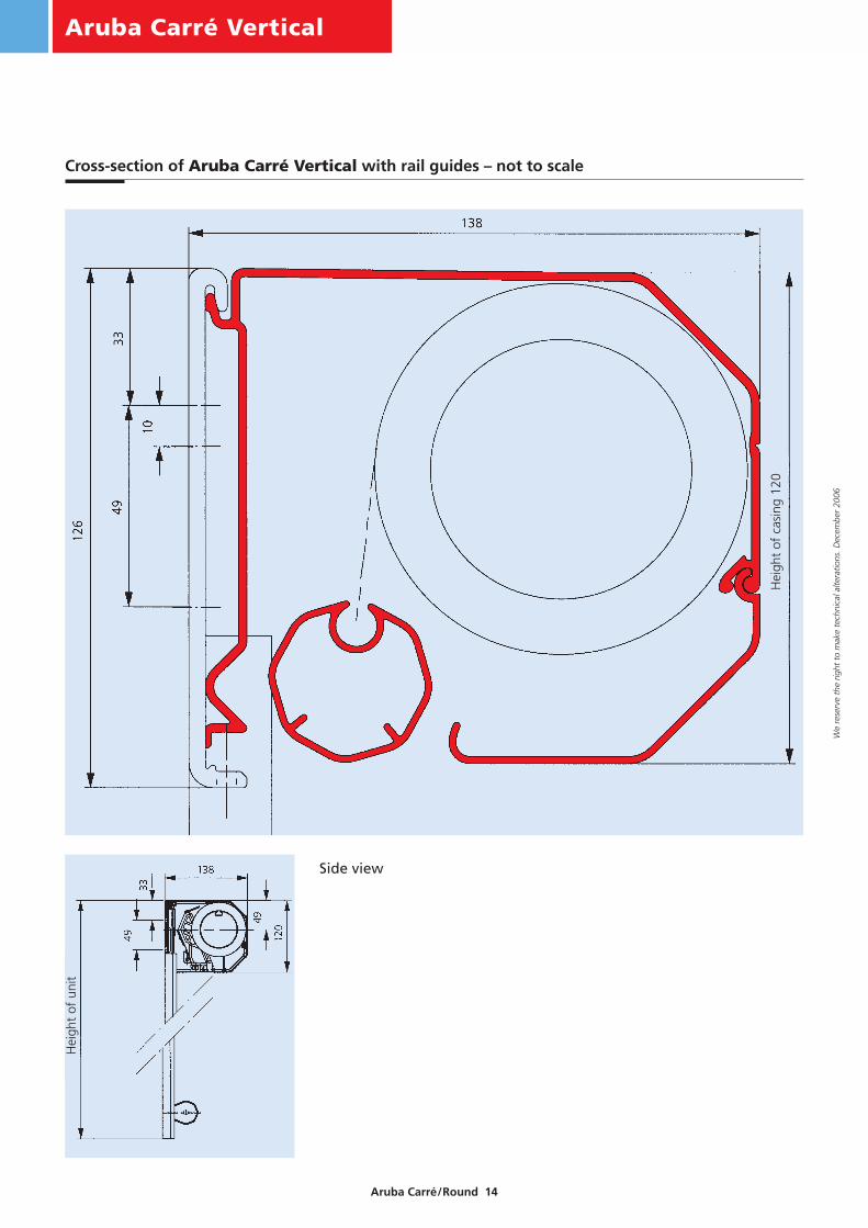
Cross-section of Aruba Carré Vertical with rail guides – not to scale
Side view
Hei
ght
of c
asin
g 12
0
Hei
ght
of u
nit

Aruba Carré Vertical
Aruba Carré/Round 15
We
rese
rve
the
right
to
mak
e te
chni
cal a
ltera
tions
. Dec
embe
r 20
06
Assembly configuration of the Aruba Carré Vertical with rail guides
Coupling the Aruba Carré Vertical with rail guides
Four-section unit
max. 150max. 150
Width of unit B22.5
Width of unit B
M6/M8
77.538 77.5
Width of unit B Width of unit B
3822.5
M6
10
15 50 50 50 15
10
B - 50B - 50B - 50B - 50
*
26
Exit formotor cableExample:left fromoutside
32
Possible locations for offsetcrank handle 90°Example: right from outside
On request with order,state “drive access 90°upwards”*
32
26 Standard
34
Width of unit B
Hei
ght
of u
nit
H
* 1.6 cm play required on bearing side for assembly.
* see also page 30
Note: On two- and three-section units, the dimensions of the inner units are alteredaccordingly.
Aruba Round Vertical
Aruba Carré/Round 16
We
rese
rve
the
right
to
mak
e te
chni
cal a
ltera
tions
. Dec
embe
r 20
06
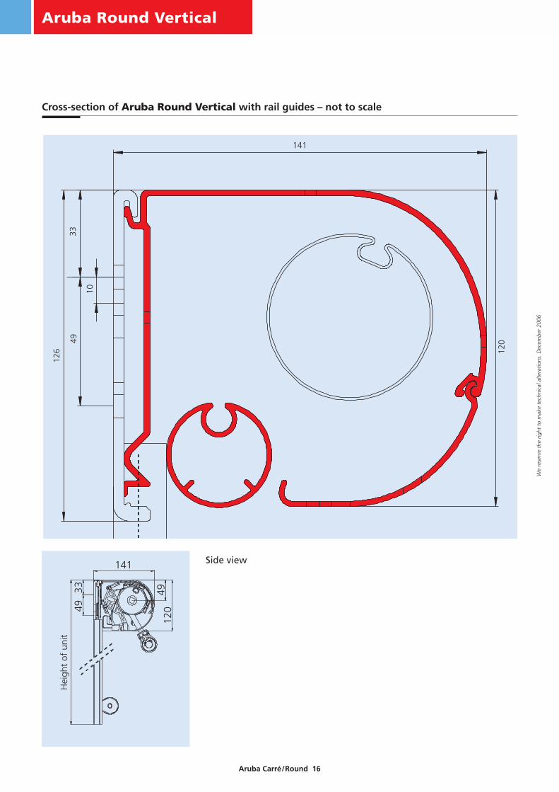
Side view
Hei
ght
of u
nit
141
120
126
4933
10
Cross-section of Aruba Round Vertical with rail guides – not to scale

Aruba Round Vertical
Aruba Carré/Round 17
We
rese
rve
the
right
to
mak
e te
chni
cal a
ltera
tions
. Dec
embe
r 20
06
max. 150max. 150
Width of unit B22.5
Width of unit B
M6/M8
77.538 77.5
Width of unit B Width of unit B
3822.5
M6
12
15 54 54 54 15
12
B - 54B - 54B - 54B - 54
*
28
Exit formotor cableExample:left fromoutside
32
Possible locations foroffset crank handle 90°Example: right from outside
On request withorder, state “driveaccess 90° upwards”*
3234
28Standard
Width of unit B
Hei
ght
of u
nit
H
Coupling the Aruba Round Vertical with rail guides
Assembly configuration of the Aruba Round Vertical with rail guides
Four-section unit
* 1.6 cm play required on bearing side for assembly.
Note: On two- and three-section units, the dimensions of the inner units are alteredaccordingly.
* see also page 30

Aruba Carré Vertical
Aruba Carré/Round 18
We
rese
rve
the
right
to
mak
e te
chni
cal a
ltera
tions
. Dec
embe
r 20
06
Side view
120
49
138
334912
6
Hei
ght o
f uni
t
Cross-section of Aruba Carré Vertical with wire guides – not to scale
Hei
ght
of c
asin
g 12
0

Aruba Carré Vertical
Aruba Carré/Round 19
We
rese
rve
the
right
to
mak
e te
chni
cal a
ltera
tions
. Dec
embe
r 20
06
22.5
max. 150
1450
77.5
5050
M6/M8
M6/M8
11
22.5
max. 150
38
B - 50
Width of unit B
B - 50
Width of unit B
38
11
14
77.5
B - 50
Width of unit B Width of unit B
B - 50
*
26
Exit formotor cableExample:left fromoutside
32
Possible locations foroffset crank handle 90°Example: right from outside
On request withorder, state “driveaccess 90° upwards”*
3234
Standard26
Hei
ght
of u
nit
H
Width of unit B
Coupling the Aruba Carré Vertical with wire guides
Assembly configuration of the Aruba Carré Vertical with wire guides
Four-section unit
* 1.6 cm play required on bearing side for assembly.
Note: On two- and three-section units, the dimensions of the inner units are alteredaccordingly.
* see also page 30
Aruba Round Vertical
Aruba Carré/Round 20
We
rese
rve
the
right
to
mak
e te
chni
cal a
ltera
tions
. Dec
embe
r 20
06
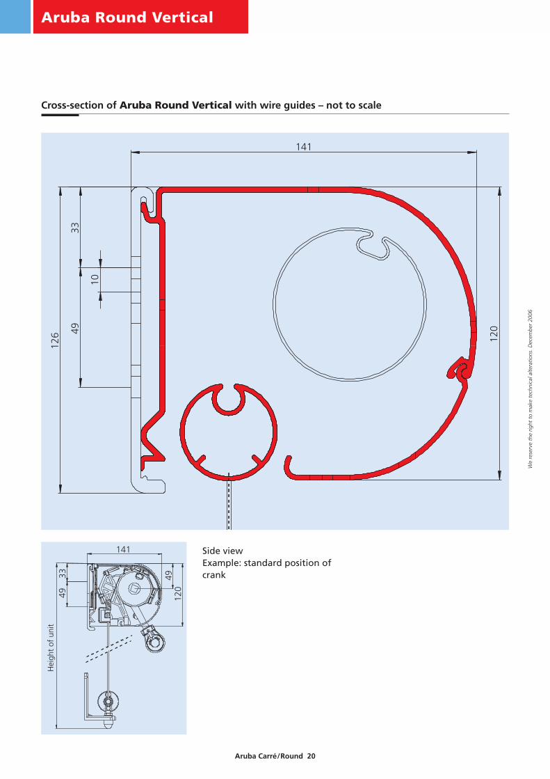
Side viewExample: standard position ofcrank
Hei
ght
of u
nit
Cross-section of Aruba Round Vertical with wire guides – not to scale

Aruba Round Vertical
Aruba Carré/Round 21
We
rese
rve
the
right
to
mak
e te
chni
cal a
ltera
tions
. Dec
embe
r 20
06
22.5
max. 150
1454
77.5
5454
M6/M8
M6/M8
13
22.5
max. 150
38
B - 54
Width of unit B
B - 54
Width of unit B
38
13
14
77.5
B - 54
Width of unit B Width of unit B
B - 54
*
28
Exit formotor cableExample:left fromoutside
32
Possible locations foroffset crank handle 90°Example: right from outside
On request withorder, state “driveaccess 90° upwards”*
3234
28
Standard
Hei
ght
of u
nit
H
Width of unit B
Coupling the Aruba Round Vertical with wire guides
Assembly configuration of the Aruba Round Vertical with wire guides
Four-section unit
* 1.6 cm play required on bearing side for assembly.
Note: On two- and three-section units, the dimensions of the inner units are alteredaccordingly.
* see also page 30
Aruba Carré Droparm
Aruba Carré/Round 22
We
rese
rve
the
right
to
mak
e te
chni
cal a
ltera
tions
. Dec
embe
r 20
06
33
13
126
49
1
138
104
Nom
inal
leng
th o
f ar
ms
65
4982
120
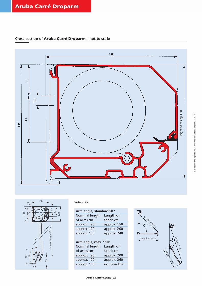
138 Side view
Arm angle, standard 90°Nominal length Length of of arms cm fabric cmapprox. 90 approx. 150approx. 120 approx. 200approx. 150 approx. 240
Arm angle, max. 150°Nominal length Length of of arms cm fabric cmapprox. 90 approx. 200approx. 120 approx. 260approx. 150 not possible
Cross-section of Aruba Carré Droparm – not to scale
Hei
ght
of c
asin
g 12
0
Length of arms
Length of arms
Length of fabric
Length of fabric

26
Exit formotor cableExample:left fromoutside
32
Possible locations foroffset crank handle 90°Example: right from outside
On request withorder, state “drive
access 90°upwards”*
3234
26Standard
16,5*
34,5*
52,5*
Width of unit B
Nom
inal
leng
th o
f ar
ms
L
B - 69 on drives with eye
Aruba Carré Droparm
Aruba Carré/Round 23
We
rese
rve
the
right
to
mak
e te
chni
cal a
ltera
tions
. Dec
embe
r 20
06
* These dimensions apply to units with standarddrive
**These dimensions apply to units with motor oroffset crank handle
max. 150 38 77.5
Width of unit B Width of unit B
B - 45
22.5
B - 4518 B - 45
Width of unit B
4545
M6/M8
M6/M8
4.5
77.5
9
45
Width of unit B
max. 150
B - 45 18
4.5
3822.5
*
Coupling Aruba Carré Droparm
Assembly configuration of the Aruba Carré Droparm
Four-section unit
* 1.6 cm play required on bearing side for assembly.
Note: On two- and three-section units, the dimensions of the inner units are alteredaccordingly.
* see also page 30

Aruba Round Droparm
Aruba Carré/Round 24
We
rese
rve
the
right
to
mak
e te
chni
cal a
ltera
tions
. Dec
embe
r 20
06
Nom
inal
leng
th o
f ar
ms
Length of fabric
Nominal lengthof arms
Length of fabric
Nominal length
of arms
Side view
Cross-section of Aruba Round Droparm – not to scale
Arm angle, standard 90°Nominal length Length of of arms cm fabric cmapprox. 90 approx. 150approx. 120 approx. 200approx. 150 approx. 240
Arm angle, max. 150°Nominal length Length of of arms cm fabric cmapprox. 90 approx. 200approx. 120 approx. 260approx. 150 not possible
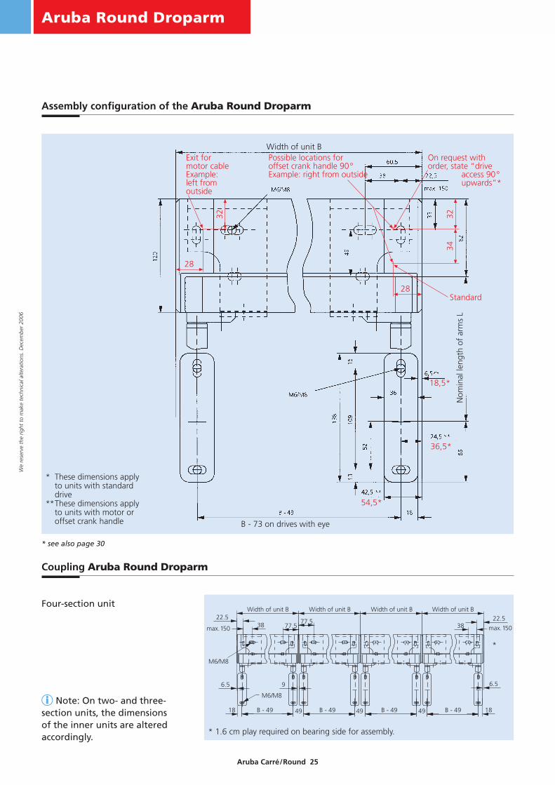
28
Exit formotor cableExample:left fromoutside
32
Possible locations foroffset crank handle 90°Example: right from outside
On request withorder, state “drive
access 90°upwards”*
3234
28Standard
18,5*
36,5*
54,5*
Nom
inal
leng
th o
f ar
ms
L
B - 73 on drives with eye
Width of unit B
Aruba Round Droparm
Aruba Carré/Round 25
We
rese
rve
the
right
to
mak
e te
chni
cal a
ltera
tions
. Dec
embe
r 20
06
max. 150 38 77.5
Width of unit B Width of unit B
B - 49
22.5
B - 4918 B - 49
Width of unit B
4949
M6/M8
M6/M8
6.5
77.5
9
49
Width of unit B
max. 150
B - 49 18
6.5
3822.5
*
Coupling Aruba Round Droparm
Assembly configuration of the Aruba Round Droparm
Four-section unit
* 1.6 cm play required on bearing side for assembly.
Note: On two- and three-section units, the dimensions of the inner units are alteredaccordingly.
* see also page 30
* These dimensions apply to units with standarddrive
**These dimensions apply to units with motor oroffset crank handle

Aruba Carré Markisolette
Aruba Carré/Round 26
We
rese
rve
the
right
to
mak
e te
chni
cal a
ltera
tions
. Dec
embe
r 20
06
Side view
4912
0
138
Hei
ght
of u
nit
4933
Hei
ght
of u
nit
Length of arms
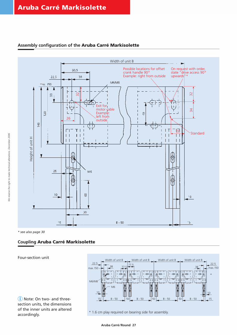
Unit height 85 – 140 cm: Standard armangle 90°, stop position atvery bottom,can be alteredeasily frombuilding, standard armlength 60 cm
Unit heightabove 140 cm:standard armangle 150°stop position: 52 cm
Cross-section of Aruba Carré Markisolette – not to scale
Hei
ght
of c
asin
g 12
0
Ove
rall
heig
ht a
ppro
x. 1
36
Hei
ght
of u
nit
Aruba Carré Markisolette
Aruba Carré/Round 27
We
rese
rve
the
right
to
mak
e te
chni
cal a
ltera
tions
. Dec
embe
r 20
06
max. 150max. 150
Width of unit B22.5
Width of unit B
M6/M8
77.538 77.5
Width of unit B Width of unit B
3822.5
M6
10
15 50 50 50 15
10
B - 50B - 50B - 50B - 50
*
26
Exit formotor cableExample:left fromoutside
32
Possible locations for offsetcrank handle 90°Example: right from outside
On request with order,state “drive access 90°upwards”*
32
26 Standard
34
Width of unit B
Hei
ght
of u
nit
H
Coupling Aruba Carré Markisolette
Assembly configuration of the Aruba Carré Markisolette
Four-section unit
* 1.6 cm play required on bearing side for assembly.
Note: On two- and three-section units, the dimensions of the inner units are alteredaccordingly.
* see also page 30

Aruba Round Markisolette
Aruba Carré/Round 28
We
rese
rve
the
right
to
mak
e te
chni
cal a
ltera
tions
. Dec
embe
r 20
06
Hei
ght
of u
nit
Nom
inal
leng
th o
f ar
ms
Cross-section of Aruba Round Markisolette – not to scale
Side view
Hei
ght
of u
nit
Nominal length of arm
s
Hei
ght
of u
nit
Nominal length of arms
Unit height 85 – 140 cm: standard armangle 90°, stop position atvery bottom,can be alteredeasily frombuilding, standard armlength 60 cm
Unit heightabove 140 cm:standard armangle 150°stop position: 52 cm

Aruba Round Markisolette
Aruba Carré/Round 29
We
rese
rve
the
right
to
mak
e te
chni
cal a
ltera
tions
. Dec
embe
r 20
06
max. 150max. 150
Width of unit B22.5
Width of unit B
M6/M8
77.538 77.5
Width of unit B Width of unit B
3822.5
M6
12
15 54 54 54 15
12
B - 54B - 54B - 54B - 54
*
28
Exit formotor cableExample:left fromoutside
32
Possible locations foroffset crank handle 90°Example: right from outside
On request withorder, state “driveaccess 90° upwards”*
32
28 Standard
34
Hei
ght
of u
nit
H
Width of unit B
Coupling Aruba Round Markisolette
Assembly configuration of the Aruba Round Markisolette
Four-section unit
* 1.6 cm play required on bearing side for assembly.
Note: On two- and three-section units the dimensions of the inner units are alteredaccordingly.
* see also page 30

Aruba Carré/Round
Aruba Carré/Round 30
We
rese
rve
the
right
to
mak
e te
chni
cal a
ltera
tions
. Dec
embe
r 20
06
Offset crank handle Markisolette/Vertical
Droparm crank handle
max. 410
appr
ox. 2
3.5
appr
ox.1
7.5
appr
ox.6
5
Wall thicknessmax. 410
app
rox.
32
appr
ox.1
0.5
appr
ox.1
6.5
Wall thickness
max. 440
appr
ox. 6
5
appr
ox.1
7.5
appr
ox. 2
3.5
Wall thickness
appr
ox. 3
2
appr
ox. 1
6.5
appr
ox. 1
0.5
max. 440Wall thickness
Standard horizontal location of offset crank handle
Warning: In this case, the bottom rail of theMarkisolette retracts by 7 mm less. Consequently,the total height of the casing is approx. 143 mm(Standard 136 mm).
Special order: Location of offset crank handlehorizontal; higher due to different position of drive
Warning: In this case, the casing bearing must bemoved at least 20 mm inwards.
Standard horizontal location of offset crank handle Special order: Location of offset crank handlehorizontal; higher due to different position of drive

Aruba Carré/Round
Aruba Carré/Round 31
We
rese
rve
the
right
to
mak
e te
chni
cal a
ltera
tions
. Dec
embe
r 20
06
Aruba Vertical/Markisolette – Standard handle position 30° towards front
30°
Aruba Carré/Round
Aruba Carré/Round 32
We
rese
rve
the
right
to
mak
e te
chni
cal a
ltera
tions
. Dec
embe
r 20
06
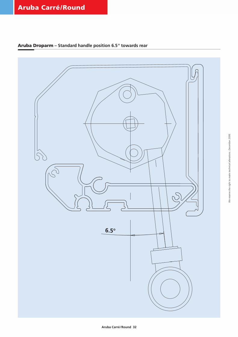
Aruba Droparm – Standard handle position 6.5° towards rear
6.5°

Aruba Carré/Round
Aruba Carré/Round 33
We
rese
rve
the
right
to
mak
e te
chni
cal a
ltera
tions
. Dec
embe
r 20
06
Punched holes: guide rail Aruba Vertical
Length of guide rail Standard number of holes for affixing the guide rail
50 cm to 87 cm 296 cm to 170,9 cm 3
171 cm to 245,9 cm 4246 cm to 260 cm 5
Punched holes: guide rail Aruba Markisolette
Length of guide rail Standard number of holes for affixing the guide rail
85 cm to 140,4 cm 2140,5 cm to 215,4 cm 3215,5 cm to 260 cm 4

Aruba Carré/Round
Aruba Carré/Round 34
We
rese
rve
the
right
to
mak
e te
chni
cal a
ltera
tions
. Dec
embe
r 20
06
Standard attachment
12,5
R 4,5R 4,5
R 4,5
30,5
9,515
2510
33
5
50
85
82
9
125,
5
M6
Casing bracket, left or right
Standard attachment for droparm versions
138
104
36
10
9
9
10
Arm wall bracket
Standard attachment for wire versions
8
10
9
12
9
22
10 Fens
ter
Fensterbank
ca. 3
0
Wire bracket
8,5
25
25
285
60
90
7
7
60

Aruba Carré/Round
Aruba Carré/Round 35
We
rese
rve
the
right
to
mak
e te
chni
cal a
ltera
tions
. Dec
embe
r 20
06
Special attachment for wire versions
3
7,5
136,
8
3
6,8
15,5
40
607
407
8,5
25
25
285
60
Windowsill
appr
ox. 3
0Win
dow
Wire bracket, small
Win
dow
Windowsill
Windowsill wire bracket

Aruba Carré/Round
Aruba Carré/Round 36
We
rese
rve
the
right
to
mak
e te
chni
cal a
ltera
tions
. Dec
embe
r 20
06
Special attachment for Vertical/Markisolette versions
Small embrasure bracket for guide section
6,5
28
24 12
50
25
10
924 1250
Warning!leave enoughspace forattachmentup to 10
Warning!leave at least 4 mm space behind bracket for screw head
Narrow embrasure bracket for guide section
40
80
50
28
6,5
149
up t
oup
per
edge
of c
asin
g
50
25
10
109
60
Warning!leave enoughspace forattachmentup to 10
149
up t
oup
per
edge
of c
asin
g
Warning!leave at least 4 mm space behind bracket for screw head

Aruba Carré/Round
Aruba Carré/Round 37
We
rese
rve
the
right
to
mak
e te
chni
cal a
ltera
tions
. Dec
embe
r 20
06
Special attachment for Vertical/Markisolette versions
Wide embrasure bracket for guide section
40
80
6,5
28
60
60
910
10
25
60
10 to 20
20
Casing bracket reinforcement
30
33
49120
9
2
Leng
th =
Hei
ght o
f uni
t
20
Guide section reinforcement
19,510
,5
85
30
2
Warning!with offset handle:length height of unit –125
Warning!leave at least 4 mm space behind bracket for screw head
149
up t
oup
per
edge
of c
asin
g

Aruba Carré/Round
Aruba Carré/Round 38
We
rese
rve
the
right
to
mak
e te
chni
cal a
ltera
tions
. Dec
embe
r 20
06
Special attachment for droparm versions
Embrasure bracket for arm wall bracket
60
2511
0
15
140
5
10
9
Long embrasure bracket for arm wall bracket
Casing bracket mounting plate
t = 5
33
10
10
933
10
65
49
15 15130
10
5 M6
6,5
10
60
14
30
112
140
Warning!leave at least 4 mm space behind bracket for screw head

Aruba Carré/Round
Aruba Carré/Round 39
We
rese
rve
the
right
to
mak
e te
chni
cal a
ltera
tions
. Dec
embe
r 20
06
Special attachment
Embrasure bracket for casingbracket
60
50
920
25
10
6,5
10 49
25,5
100
25
Ceiling bracket for casing bracket
100
49
120
5
49
M6
50
60
25
9
50
20
2,5
Spacer
10,5
30
min. 13
136
11 16
Warning!leave at least 4 mmspace behindbracket for screwhead
Warning!space for screw head
(– 13 mm for M8)
with narrow embrasure bracketor small embrasure bracket
with wide embrasure bracket
1118
max. 13
max. 25

Aruba Carré/Round
Aruba Carré/Round 40
We
rese
rve
the
right
to
mak
e te
chni
cal a
ltera
tions
. Dec
embe
r 20
06
Special attachment for coupling wire version
Special attachment for coupling droparm version
Wire bracket coupling mounting plate
9
60
30
10
14
140t = 5
6,5 10
55
120
Windowsill wire bracket Glass
Glass
36
up to14
min. 28 min. 28Warning!
leave at least 4 mm space behind bracket for screw head

Aruba Carré/Round
Aruba Carré/Round 41
We
rese
rve
the
right
to
mak
e te
chni
cal a
ltera
tions
. Dec
embe
r 20
06
Special attachment for coupling Markisolette/Vertical versions
Special attachment for coupling
Guide section coupling mounting plate
t = 5
10
160
190
15
48
49
33
9M6
10
120
Casing bracket couplingmounting plate
Glass Glass
20
80
50
Glas Glas
60 e.g.Window frame
Hei
ght
of u
nit
H