the analysis on hybrid superconducting fault current
TRANSCRIPT

JEEMECS (Journal of Electrical Engineering, Mechatronic and Computer Science ISSN 2614-4859 Vol. 3, No. 1, February 2020, pp. 33-46 https://doi.org/10.26905/jeemecs.v3i1.3931
33 | P a g e http://jurnal.unmer.ac.id/index.php/jeemecs [email protected]
The Analysis On Hybrid Superconducting Fault Current Limiter (SFCL) Usage To Limit Short Circuit Fault Current Of 20 Kv Electric Power Distribution In Sengkaling Substation
Eko Nurcahyo a,1,*, Bambang Prio Hart a,2, Choirul Saleh a,3
a Institute Technology National Malang, Malang, Indonesia 1 [email protected] *; 2 [email protected]; 3 [email protected] * corresponding author
1. Introduction
Sengkaling Substation, Malang is a part of distribution system which is located in the area of PT. PLN (State Electrical Company) Malang. Electrical energy usage in Sengkaling Substation tends to be arising every year. This is due to how rapid the development is in Malang and Batu. One of the issues that has occurred in Sengkaling substation is the frequent occurrence of short circuit fault current which happened for ±18 times throughout 2016. These short circuit fault current happened because of extreme weather which triggered relay trip in feeder supplied by power transformator 4.
With the arising of electrical energy need and bad weather, it demands improvement in operational work of substation and its equipment as the fault increases, the short circuit fault will occur specifically. In order to protect the equipment and the whole electrical system, and to reduce the short circuit fault current quickly within timeframe of ½ cycle, it requires Superconducting Fault Current Limiter (SFCL)[1] which is going to be placed on the bus that comes close to a critical point.
2. The Proposed Method/Algorithm
2.1. Fault in Electrical Power System
Fault in electrical power system is an abnormal state that causes the disruption in electrical power service continuity. Based on its origin, there are two types of fault; fault that is originated from inside the system and one that is originated from outside the system. While based on its nature, fault is divided into two which are temporary and permanent fault. Short circuit fault is caused by phase channel connected to another phase channel or connected to the ground. Short circuit fault may happen in two phases, two phases to the ground, three phases to the ground, and one phase to the ground[3].
AB ST R ACT
Keywords
SFCL
Short circuit current
Hybrid SFCL
The occurrence of fault in electrical power system operation is inevitable. The causes of fault in electrical power transmission and distribution system for instances are lighting strikes on transmission canal, tree collapses, or short circuit inter-phases to the ground. In order to protect the equipment and the whole electrical system in Sengkaling Substation and to reduce the short circuit fault current quickly within timeframe of ½ cycle, it requires Superconducting Fault Current Limiter (SFCL) which is going to be placed on the bus that comes close to a critical point. The designing and analysis on the system of before and after hybrid SCFL installment utilize PSCAD software. The simulation result obtained by installing hybrid SFCL in incoming bus 2 (20 kV) was that hybrid SFCL was able to reduce short circuit fault current in ½ initial cycle with L-G fault of 16.77 kA changed to 5.9 kA, L-L-G fault of 35.38 kA changed to 9.15 kA, L-L-L-G fault of 38.36 kA changed to 9.8 kA, and L-L fault of 28.89 kA changed to 4.35 kA. The average percentage of short circuit fault current that was reduced by hybrid SFCL was 74.12%.

JEEMECS (Journal of Electrical Engineering, Mechatronic and Computer Science ISSN 2614-4859 Vol. 3, No. 1, February 2020, pp. 33-46 https://doi.org/10.26905/jeemecs.v3i1.3931
34 | P a g e http://jurnal.unmer.ac.id/index.php/jeemecs [email protected]
2.2. Superconductor Fault Current Limiter (SFCL)
Superconducting Fault Current Limiter (SFCL) is a tool which is able to limit fault current occurs in electrical power network. By applying SFCL, then the occurring fault current is going to be quickly reduced by utilizing the impedance from SFCL[3]. SFCL has an extremely low impedance when it is in a normal state, however when it is in fault state, it has a highly high impedance.
One SFCL is able to limit short circuit fault within less than a half cycle. There are two category of SFCL which are resistive SFCL and saturated ironcore SFCL.
2.3. Resistive Superconducting Fault Current Limiter (SFCL)
Resistive Superconducting Fault Current Limiter (SFCL) is equipped with High Temperature Superconductor (HTS). HTS component is the main component of resistive SFCL. HTS component consists of Superconductor and cooler (Cryostat)[3]. Initially, resistive SFCL only consists of HTS component. Along with the technology development, resistive SFCL has developed into hybrid resistive SFCL with a conventional breaker and hybrid resistive SFCL with fast switch.
2.4. Hybrid Superconducting Fault Current Limiter (SFCL)
Hybrid SFCL is a tool which is able to limit fault current occurs in electrical power network. The outstanding development lies on the part which superconductor does not function as the delimiter for short circuit current but rather only as the sensing for short circuit current and as the switcher for short circuit current to take a turn to Current Limiting Reactor (CLR). Fundamentally, hybrid SFCL consists of three main parts which are fast switch, current delimiter (current limiting part) and high temperature superconductor (HTS)[3]. The structure of hybrid SFCL uses fast switch which is combined with two mechanical switch (vacuum interrupter (VI)) and short bar (SB), driving coil and electromagnetic plate (EM) [2].
Fig. 1. Hybrid SFCL Configuration Sequence
a. Normal Operational State In a normal state, superconductor operational temperature was maintained at 77 Kelvin. In this state, HTSC had the impedance of 0 ohm as if it became a conductor with no restriction. Figure 2.2 is a hybrid SFCL sequence in a normal operational state.
Fig. 2. Normal Operational State

JEEMECS (Journal of Electrical Engineering, Mechatronic and Computer Science ISSN 2614-4859 Vol. 3, No. 1, February 2020, pp. 33-46 https://doi.org/10.26905/jeemecs.v3i1.3931
35 | P a g e http://jurnal.unmer.ac.id/index.php/jeemecs [email protected]
b. Sensing State When Fault Current Occurs When fault current flows through HTSC and produces heat, it caused HTSC resistance value to increase which triggered fault current to reroute towards drive coil and breaking switch. Figure 2.8 is a hybrid SFCL sequence in sensing state when fault current occurred.
Fig. 3. Sensing State When Fault Current Occurs
c. Fault Occurrence State After Coil is Active When the current in drive coil hit a certain setting limitation, then magnetic field force produced by the coil would drive SWa, which was initially in a normally open state, to normally close, and would drive SWb, which initially was in a normally close, to normally open. Thus, fault current would flow through SWa and CLR. Fault current that goes through CLR was limited prior to the first ½ cycle[5]. Figure 2.9 is a hybrid SFCL sequence in the fault occurrence state after coil was active.
Fig. 4. Fault Occurrence State After Coil was Active
3. Method
3.1. Material and Equipment Used
Materials and equipment used were computer with which it used PSCAD softwares for the testing and calculation.
3.2. Location and Time of Data Collection
Data collection location for this study was technical data belongs to Sengkaling Substation which is one of the substations managed by authorization of PT. PLN P3B for East Java and Bali. The time for data collection was performed in November 1st to November 29th, 2018 as in accordance to requirements set by APP (state company) Malang.
3.3. Data Collection Technique
3.3.1. Direct Observation
By applying this technique, the data needed was specifically the one that relates to general description of observed object which was in regard to what kind of fault occurred in Sengkaling Substation. Thus, this data could be utilized as materials for interview.

JEEMECS (Journal of Electrical Engineering, Mechatronic and Computer Science ISSN 2614-4859 Vol. 3, No. 1, February 2020, pp. 33-46 https://doi.org/10.26905/jeemecs.v3i1.3931
36 | P a g e http://jurnal.unmer.ac.id/index.php/jeemecs [email protected]
3.3.2. Interview
As a start, open interview was performed based on the hands-on observation result data. The next was to perform methodology interview on “The Analysis on Hybrid Superconducting Fault Current Limiter (SFCL) Usage to Limit Short Circuit Fault Current in 150/20 Kv Distribution Network in Sengkaling Substation, Malang” either in separate interviews or focus discussion groups.
3.3.3. Review of Related Literature
Review of related literature was depicted to acquire theories on which it was created as the basis of this study. This study covers the theory comprehension and concept, and suitable method to form framework of thinking in order for this study to be logical and more focused.
3.4. Execution Stages
In order to create the usage simulation on Hybrid Superconducting Fault Current Limiter (SFCL)[6][7] [2]to limit fault short circuit, several stages were performed as below: 1. Entered input data from a single line diagram of Sengkaling Substation which is in a form of
transformator data, load data which is in a form of bus data fixed load (P+jQ load), and entered safety data into PSCAD.
2. Performed running simulation on electrical system which was already modeled in PSCAD. 3. Analyzed base case state as the reference for current either in a normal state or fault occurrence
state Hybrid Superconducting Fault Current Limiter (SFCL). 4. The next stage was regarding the state which short circuit fault current occurs in a busbar that
possessed the highest current. The analysis on short circuit current fault is divided into 4 cases, they are:
Short circuit fault of one phase to the ground (L-G)
Short circuit fault of phase to phase (L-L)
Short circuit fault of two phases to the ground (L-L-G)
Short circuit fault of three phases to the ground (L-L-LG) 5. Then, analyzed whether the amount of currect that flows through was bigger than the nominal
current or not. 6. If it was bigger, then the correct calculation for parameter setting was performed in every Hybrid
Superconducting Fault Current Limiter (SFCL) component. 7. The next was performing installation of Hybrid Superconducting Fault Current Limiter (SFCL)
to limit short circuit fault current. 8. After short circuit fault current was eliminated, then running simulation was redid by considering
the state whether it was still within the limit of current that flows through was bigger than nominal current. If it was still within the limit as it was stated previously, then returned to point 6. If it was not, proceeded to the next point.
9. After that, comparing the result that had been tested among base case states, then the state with short circuit fault current without installation of Hybrid Superconducting Fault Current Limiter (SFCL), and short circuit fault current state with installation of Hybrid Superconducting Fault Current Limiter (SFCL). Setelah itu membandingkan hasil yang telah di uji coba antara kondisi base case, kemudian kondisi dengan arus gangguan hubung singkat tanpa pemasangan Hybrid Superconducting Fault Current Limiter (SFCL) , dan kondisi arus gangguan hubung singkat dengan pemasangan Hybrid Superconducting Fault Current Limiter (SFCL) .
10. Done.
See the below flowchart for more details regarding the Hybrid Superconducting Fault Current Limiter (SFCL) usage to limit short circuit fault current using PSCAD software.

JEEMECS (Journal of Electrical Engineering, Mechatronic and Computer Science ISSN 2614-4859 Vol. 3, No. 1, February 2020, pp. 33-46 https://doi.org/10.26905/jeemecs.v3i1.3931
37 | P a g e http://jurnal.unmer.ac.id/index.php/jeemecs [email protected]
Fig. 5. Problem Solving Flowchart
4. Results and Discussion
4.1. Electrical System Single Line in Sengkaling Substation
Sengkaling Substation owns two distribution transformer; they are Transformer III Unindo 150/20 kV with capacity of 30 MVA/866 A and Transformer IV SHADONG 150/20 kV with capacity of 60 MVA /1732 A. Transformer III serves four feeders which are Junrejo, Pujon, Karangploso and Wastra Indah. Transformer IV serves four feeders which are Selekta, Batu, Dinoyo, and Tegalgondo. Figure 6 shows a single line diagram of Sengkaling Substation.
Fig. 6. Single Line Diagram of Sengkaling Substation Source: Sengkaling Substation

JEEMECS (Journal of Electrical Engineering, Mechatronic and Computer Science ISSN 2614-4859 Vol. 3, No. 1, February 2020, pp. 33-46 https://doi.org/10.26905/jeemecs.v3i1.3931
38 | P a g e http://jurnal.unmer.ac.id/index.php/jeemecs [email protected]
4.2. Identify the Headings
Power transformer data of Sengkaling Substation was required as transformer model data in PSCAD. Data of transformer III and IV are shown in table 4.1 below:
Table 1. Transformer Data in Sengkaling Substation
Trafo III Trafo IV Brand UNINDO SHANDONG
Type TTUB
150/30000 SFZ11-
60000/150 Power 30 MVA 60 MVA Impedance 12,5 % 12,43 % Voltage 150/20 KV 150/20 KV Grounding Impedance
500 ohm 500 ohm
Winding Circuit Ynyn0(d1) Ynyn0(d)
Source: Sengkaling Substation
4.3. Load Data
Load data from Sengkaling Substation was in a form apparent power load data (MVA). Therefore, in order to get active power P and reactive power Q in each feeder, the following equations were used:
� = ������ = �������� (��) ................................... (4.1)
� = √�� − ��(����)..................................................... .(4.2)
Table 2. Maximum Load of Sengkaling Substation
No Feeder V
(kV) Cos φ
P (MW)
Q (MVAR)
1 Tegal Gondo
20 0.85 3.247 2.017
2 Selecta 20 0.85 2.635 1.633 3 Dinoyo 20 0.85 2.907 1.801 4 Batu 20 0.85 2.261 1.401
5 Wastra Indah
20 0.85 2.669 1.654
6 Karang Ploso
20 0.85 2.091 1.295
7 Pujon 20 0.85 2.516 1.559 8 Junrejo 20 0.85 1.819 1.127
Source: Sengkaling Substation
4.4. Short Circuit Current Data
MVA value of short circuit in busbar in high voltage 150 kV part, which becomes the supply of Sengkaling Substation, is 2529,44 MVA[10]. Thus, it generated short circuit fault current value as below:
��� = 2529.44 ���
√3�150 ��= 9.736 ��
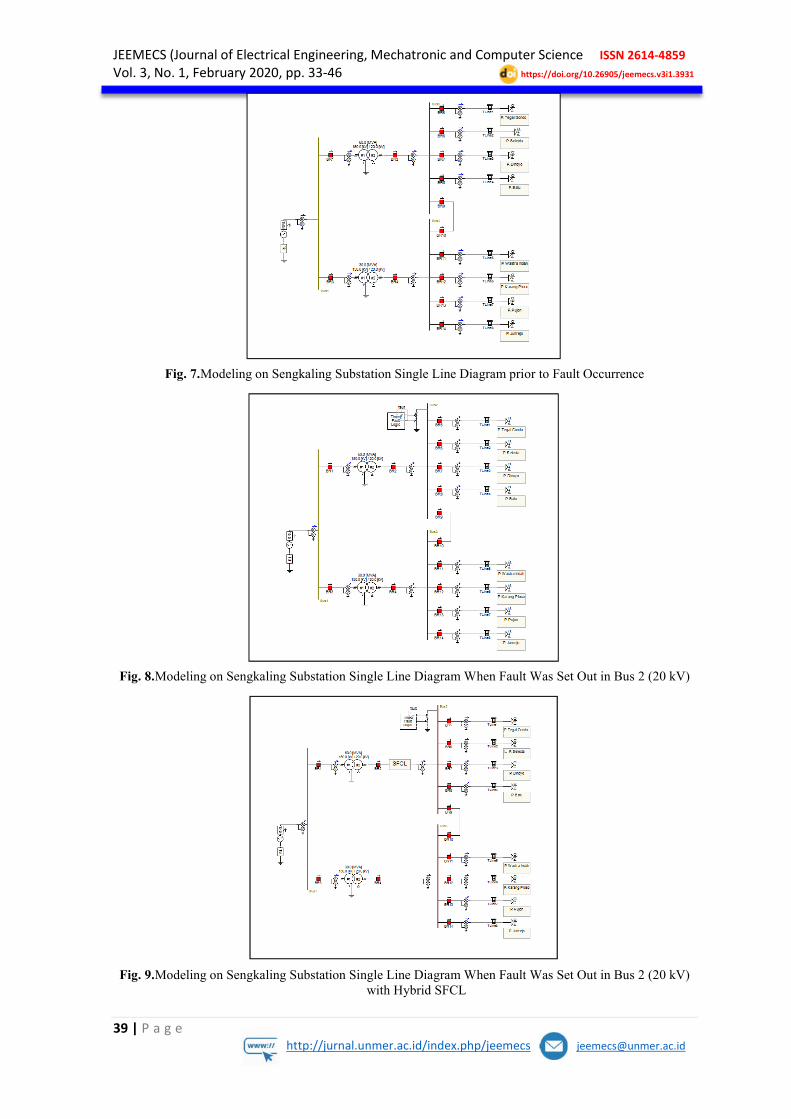
4.5. Modeling on Sengkaling Substation
Research data which were in a form of Sengkaling Substation single line diagram data, transformer data, load data, and short circuit data were depicted in PSCAD work sheet. The load in each feeder was modeled in a form of fixed load (P + jQ load). Sengkaling substation single line diagram was further being simulated.
Modeling on Sengkaling Substation single line diagram consisted of three models; they were system prior to fault occurrence, system when fault was set out, and system when fault was set out with SFCL in bus 2 (20 kV).
JEEMECS (Journal of Electrical Engineering, Mechatronic and Computer Science ISSN 2614-4859 Vol. 3, No. 1, February 2020, pp. 33-46 https://doi.org/10.26905/jeemecs.v3i1.3931
39 | P a g e http://jurnal.unmer.ac.id/index.php/jeemecs [email protected]
Fig. 7. Modeling on Sengkaling Substation Single Line Diagram prior to Fault Occurrence
Fig. 8. Modeling on Sengkaling Substation Single Line Diagram When Fault Was Set Out in Bus 2 (20 kV)
Fig. 9. Modeling on Sengkaling Substation Single Line Diagram When Fault Was Set Out in Bus 2 (20 kV) with Hybrid SFCL

JEEMECS (Journal of Electrical Engineering, Mechatronic and Computer Science ISSN 2614-4859 Vol. 3, No. 1, February 2020, pp. 33-46 https://doi.org/10.26905/jeemecs.v3i1.3931
40 | P a g e http://jurnal.unmer.ac.id/index.php/jeemecs [email protected]
4.6. Modeling on Hybrid SFCL
Fig. 10. Hybrid SFCL Construction
In order to model hybrd SFCL, fast switch was simulated by utilizing breaker (BRKA and BRKC) which functioned as a switch. BRKA was modeled as short bar (SB), BRKC was modeled as vacuum interrupter (VI), and BRKC was modeled as current limiter reactor (CLR).
In a normal state, superconductor operational temperature was maintained at 77 Kelvin. In this state, high temperature superconductor (HTSC) had impedance of 0 ohm. Fault current thar flowed through high temperature superconductor (HTSC) and generated heat, it caused high temperature superconductor (HTSC) value increasing which caused fault current to change its course to drive coil and breaking switch. When the current in drive coil hit a certain setting limit, then magnetic field force produced by coil would drive short bar (SB) switch, which was initially open, to close and drive vacuum interrupter (VI) switch, which was initially close, to open. Thus, fault current flowed through short bar (SB) switch and current limiting reactor (CLR). The fault current that flowed through current limiting reactor (CLR) was limited prior to the first ½ cycle.
Fig. 11. Modeling for Hybrid SFCL in PSCAD Work Sheet
4.7. Simulation Result
4.7.1. System Prior to Fault Occurrence
The system prior to fault occurrence showed that the form of voltage (kV) waves in bus 1 (150 kV), bus 2 (20 kV), and bus 3 (20 kV).
Fig. 12. Voltage Waves in Bus 1 prior to Fault Occurrence

JEEMECS (Journal of Electrical Engineering, Mechatronic and Computer Science ISSN 2614-4859 Vol. 3, No. 1, February 2020, pp. 33-46 https://doi.org/10.26905/jeemecs.v3i1.3931
41 | P a g e http://jurnal.unmer.ac.id/index.php/jeemecs [email protected]
Fig. 13. Voltage Waves in Bus 2 prior to Fault Occurrence
Fig. 14. Voltage Waves in Bus 3 prior to Fault Occurrence
The result of PSCAD simulation running in Figure 12, 13, and 14 showed that the amount of voltage (kV) in bus 1 prior to fault occurrence was V = 122.31 kV, voltage (kV) in bus 2 prior to fault occurrence was V = 16.05 kV, voltage (kV) in bus 3 prior to vault occurrence was V = 16.05 kV.
The form of current waves (kA) in bus 1 (150 kV), bus 2 (20 kV), and bus 3 (20 kV), when the system prior to short circuit fault, were depicted in Figure 15, 16, and 17.
Fig. 15. Current Waves in Bus 1 Prior to Fault
Fig. 16. Current Waves in Bus 2 Prior to Fault

JEEMECS (Journal of Electrical Engineering, Mechatronic and Computer Science ISSN 2614-4859 Vol. 3, No. 1, February 2020, pp. 33-46 https://doi.org/10.26905/jeemecs.v3i1.3931
42 | P a g e http://jurnal.unmer.ac.id/index.php/jeemecs [email protected]
Fig. 17. Current Waves in Bus 3 Prior to Fault
The result of PSCAD simulation running in Figure 15, 16, and 17 showed that the amount of current (kA) in bus 1 prior to fault was A = 0.1080 kA, current (kA) in bus 2 prior to fault was A = 0.5226 kA, current (kA) in bus 3 prior to fault was A = 0.2605 kA.
4.7.2. System When Fault was Set Out in Bus 2 and Hybrid SFCL Installation
The scenario for SFCL placement was based on the highest current value prior to fault. The highest current value occurred in bus 2 (20 kV) was 0.5226 kA. The following figure depicts the time when short circuit fault was set out to current waves form and voltage with and without SFCL.
A. Profiling Results on Current and Voltage before and after Hybrid SFCL Installation When One Phase Fault to the Ground (L-G) Occurred
Fig. 18. L-G Short Circuit Fault Current Waves in Bus 2 without Hybrid SFCL
Fig. 19. L-G Short Circuit Fault Current Waves in Bus 2 with Hybrid SFCL
Fig. 20. Voltage Waves When L-G Short Circuit Fault Current Occurred
The above simulation result depicts the amount of current when fault occurred in t = 0.2 s with t = 1.5 s. By installing hybrid SFCL in the position of incoming bus 2, one phase fault to the ground

JEEMECS (Journal of Electrical Engineering, Mechatronic and Computer Science ISSN 2614-4859 Vol. 3, No. 1, February 2020, pp. 33-46 https://doi.org/10.26905/jeemecs.v3i1.3931
43 | P a g e http://jurnal.unmer.ac.id/index.php/jeemecs [email protected]
experienced reduction on fault current from 16.77 kA to 5.9 kA only within ½ cycle period. It also depicts voltage waves form when it was experiencing reduction on fault up to 100%.
B. Profiling Results on Current and Voltage before and after Hybrid SFCL Installation When Two Phases Fault to the Ground (L-L-G) Occurred
Fig. 21. L-L-G Short Circuit Fault Current Waves in Bus 2 without Hybrid SFCL
Fig. 22. L-L-G Short Circuit Fault Current Waves in Bus 2 with Hybrid SFCL
Fig. 23. Voltage Waves When L-L-G Short Circuit Fault Current Occurred
The above simulation result depicts the amount of current when fault occurred in t = 0.2 s with t = 1.5 s. By installing hybrid SFCL in the position of incoming bus 2, two phases fault to the ground experienced reduction on fault current from 35.38 kA to 9.15 kA only within ½ cycle period. It also depicts voltage waves form when it was experiencing reduction on fault up to 100%.
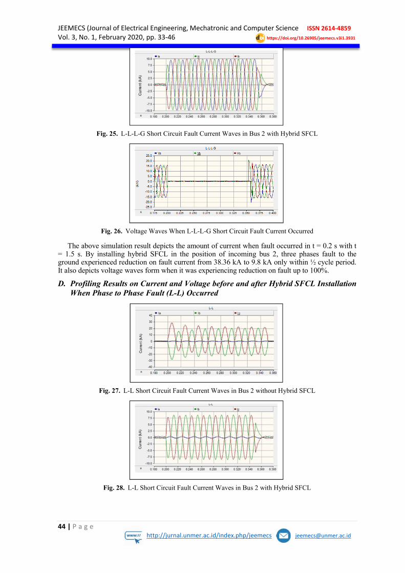
C. Profiling Results on Current and Voltage before and after Hybrid SFCL Installation When Three Phases Fault to the Ground (L-L-L-G) Occurred
Fig. 24. L-L-L-G Short Circuit Fault Current Waves in Bus 2 without Hybrid SFCL
JEEMECS (Journal of Electrical Engineering, Mechatronic and Computer Science ISSN 2614-4859 Vol. 3, No. 1, February 2020, pp. 33-46 https://doi.org/10.26905/jeemecs.v3i1.3931
44 | P a g e http://jurnal.unmer.ac.id/index.php/jeemecs [email protected]
Fig. 25. L-L-L-G Short Circuit Fault Current Waves in Bus 2 with Hybrid SFCL
Fig. 26. Voltage Waves When L-L-L-G Short Circuit Fault Current Occurred
The above simulation result depicts the amount of current when fault occurred in t = 0.2 s with t = 1.5 s. By installing hybrid SFCL in the position of incoming bus 2, three phases fault to the ground experienced reduction on fault current from 38.36 kA to 9.8 kA only within ½ cycle period. It also depicts voltage waves form when it was experiencing reduction on fault up to 100%.
D. Profiling Results on Current and Voltage before and after Hybrid SFCL Installation When Phase to Phase Fault (L-L) Occurred
Fig. 27. L-L Short Circuit Fault Current Waves in Bus 2 without Hybrid SFCL
Fig. 28. L-L Short Circuit Fault Current Waves in Bus 2 with Hybrid SFCL

JEEMECS (Journal of Electrical Engineering, Mechatronic and Computer Science ISSN 2614-4859 Vol. 3, No. 1, February 2020, pp. 33-46 https://doi.org/10.26905/jeemecs.v3i1.3931
45 | P a g e http://jurnal.unmer.ac.id/index.php/jeemecs [email protected]
Fig. 29. Voltage Waves When L-L Short Circuit Fault Current Occurred
The above simulation result depicts the amount of current when fault occurred in t = 0.2 s with t = 1.5 s. By installing hybrid SFCL in the position of incoming bus 2, phase to phase fault to the ground experienced reduction on fault current from 28.09 kA to 4.35 kA only within ½ cycle period. It also depicts voltage waves form when it was experiencing reduction on fault up to 100%.
4.8. Analysis on Simulation Result
Based on the running simulation with all sorts of fault and hybrid SFCL installation, the results are depicted in a table below:
Table 3. Fault Current without and after Hybrid SFCL Installation
Ifault (kA)
ISFCL (kA)
Difference (kA)
Presentage (%)
L-G 16.77 5.9 10.87 64.81 L-L-G 35.38 9.15 25.58 72.3 L-L-L-G 38.36 9.8 28.56 74.45 L-L 28.89 4.35 24.54 84.94
In order to simplify in analyzing simulation results, Table 4.4 can be depicted as the following graphic:
Fig. 30. System Performance Graphic prior to and after SFCL installation
It can be viewed from the graphic that there was a significant reduction occurred in system performance before and after SFCL installation. There were differences in current values before and after SFCL installation. Based on that graphic, red line is lower than blue line with reduction average percentage of 74.12%. Thus, it can be concluded that system performance has been improving after SFCL installation.
5. Conclusion
The conclusions that can be drawn from the effect of hybrid SFCL installation in Sengkaling Substation to reduce short circuit fault current by utilizing PSCAD software are: 1. Hybrid SFCL usage in Sengkaling Substation was able to reduce fault current within the first ½
cycle for L-G fault from 16.77 kA to 5.9 kA. For L-L-G fault, it was from 5.38 kA to 9.15 kA.

JEEMECS (Journal of Electrical Engineering, Mechatronic and Computer Science ISSN 2614-4859 Vol. 3, No. 1, February 2020, pp. 33-46 https://doi.org/10.26905/jeemecs.v3i1.3931
46 | P a g e http://jurnal.unmer.ac.id/index.php/jeemecs [email protected]
For L-L-LG fault, it was from 38.36 kA to 9.8 kA. And for L-L fault, it was from 28.89 kA to 4.35 kA.
2. The percentage of short circuit fault current reduction caused by hybrid SFCL was 74.12%. 3. By installing hybrid SFCL, it could improve system performance in Sengkaling Substation.
References
[1] S.-H. Lim, J.-S. Kim, and J.-C. Kim, “Analysis on protection coordination of hybrid SFCL with protective devices in a power distribution system,” IEEE Trans. Appl. Supercond., vol. 21, no. 3, pp. 2170–2173, 2010.
[2] S. M. Blair, C. D. Booth, and G. M. Burt, “Current–time characteristics of resistive superconducting fault current limiters,” IEEE Trans. Appl. Supercond., vol. 22, no. 2, p. 5600205, 2012.
[3] J.-S. Kim, S.-H. Lim, and J.-C. Kim, “Comparative analysis on current limiting characteristics of hybrid superconducting fault current limiters (SFCLs) with first half cycle limiting and non-limiting operations,” J. Electr. Eng. Technol., vol. 7, no. 5, pp. 659–663, 2012.
[4] Y. S. W. Utomo, “Analisa penggunaan Superconducting Fault Current Limiter (SFCL) untuk melindungi peralatan di PT. Pindo Deli.” Institut Teknologi Sepuluh Nopember, 2015.
[5] F. Ahlian, “Analisis Koordinasi Rele Arus Lebih Pada Penyulang Pujon Terintegrasi Dengan Pembangkit Tersebar Mikrohidro.” Universitas Brawijaya, 2015.
[6] S. Lee, J. Yoon, and B. Lee, “Analysis model development and specification proposal of hybrid Superconducting Fault Current Limiter (SFCL),” Phys. C Supercond. its Appl., vol. 470, no. 20, pp. 1615–1620, 2010.
[7] M. Sa’adah, “Analisa Penggunaan Hybrid Superconducting Fault Current Limiter (SFCL) Pada Sistem Proteksi Tenaga Listrik Di Kawasan Tursina.” Institut Teknologi Sepuluh Nopember, 2016.