the analysis of aluminium cantilever beam with ... by changing position of piezo patch over length...
TRANSCRIPT

International Research Journal of Engineering and Technology (IRJET) e-ISSN: 2395-0056
Volume: 04 Issue: 07 | July -2017 www.irjet.net p-ISSN: 2395-0072
© 2017, IRJET | Impact Factor value: 5.181 | ISO 9001:2008 Certified Journal | Page 847
The Analysis of Aluminium Cantilever Beam with Piezoelectric
Material by changing Position of piezo patch over Length of Beam
Mr. Lalit R. Shendre1, Prof. Bhamare V.G.2
1PG Student, Department of Mechanical Engineering, SNDCOE &RC, Babulgaon, India 2HOD, Department of Mechanical Engineering, SNDCOE &RC, Babulgaon, India
---------------------------------------------------------------------***---------------------------------------------------------------------
Abstract - All mechanical systems suffer from undesirable vibrations during their operations. Their occurrence is uncontrollable as it depends on various factors. However, for efficient operation of the system, these vibrations have to be controlled within the specified limits. In ACV the vibration of a structure is reduced by using opposite directional force to the structure. Now a day's active vibration control is frequently being used in aircraft engines, submarine, robotic actuators, antennas of spaceships, aircraft wings, automobile, helicopter blade, naval vessel. In this project a smart beam (aluminum beam) with one pair of piezoelectric lamination is used to study the active vibration control. The smart beam consists of rectangular aluminum beam modeled in cantilever configuration with surface bonded piezoelectric patches. The study uses ANSYS-16 software to derive the finite element model of the smart beam. A beam is modeled in Ansys design modeller & analyze in Ansys workbench, in which Undamped Natural Frequencies are obtained by solving the Eigen Value problem using Subspace Iteration method for cantilever beam.
Key Words: Actuators, ANSYS, Controller, Oscilloscope, PZT, Sensors, smart structure, Vibrations.
1. INTRODUCTION
Vibration is a motion of a particle or a body or system of connected bodies displaced from a equilibrium. Vibration occurs when a system is displaced from a position of stable equilibrium. The system tends to return to this equilibrium position under the action of restoring forces (such as the elastic forces, as for a mass attached to a spring, or gravitational forces, as for a simple pendulum). The system keeps moving back and forth across its position of equilibrium.
The control algorithm that can be used to suppress
the vibrations occurring in the system is direct feedback of the output parameter back into system. Measurable parameters like strain, displacement, velocity & acceleration are the commonly fed signals. This type of control is simple to implement and yet yields satisfactory results. The system parameters
are analysed through the free vibration test. The setup consisted of one Lead-Zirconate-Titanate (PZT) patch producing the primary disturbance (the exciter), another PZT patch sensing the occurring disturbance (the sensor), and finally the third PZT patch that suppressed the vibration (the actuator). The existence of the PZT patches shifts the natural frequencies of the passive structure to higher frequencies. used piezoelectric material on a cantilever beam thereby making it smart. The placement of the piezo sensors and actuators on the beam were determined through modal analysis.
2. LITERATURE REVIEWS
Nitin N More in his paper [1] explore the modeling and analysis of piezoelectric-based vibration extraction devices using Matlab and Ansys software. Static and dynamic analysis of piezoelectric cantilever is carried out in Ansys. He performed Static analysis of piezoelectric bimorph beam to determine deflection, using Ansys.
Yogesh S. Powar & Prof. A.M. Naniwadikar in their research paper [2] explored the complete finite element analysis of a cantilever beam having PZT5A patch with SDOF system for constant input amplitude. The results are verified with experimental results. This paper highlights on the energy harvesting of piezoelectric material (PZT5A) by using single degree of freedom system to cantilever beam.
Zhi-cheng qui, hong xin wu in their research paper
[3] have explores the dynamic behavior of laminated composite box structure containing piezoelectric actuators and sensors for active vibration control is studied by finite element method. They uses commercial finite element package program ANSYS 8.1, in which SOLID46 elements are used for the metal part and SOLID5 elements are used for the piezoelectric part of the structure.
Harijono Djojodihardjo, Mohammad Jafari, Surjatin Wiriadidjaja in their research paper [4] they study the
International Research Journal of Engineering and Technology (IRJET) e-ISSN: 2395-0056
Volume: 04 Issue: 07 | July -2017 www.irjet.net p-ISSN: 2395-0072
© 2017, IRJET | Impact Factor value: 5.181 | ISO 9001:2008 Certified Journal | Page 848
effect of varying test factors on decay time and vibration level on a panel-beam system with viscoelastic material applied. The results were calculated using DOE software, and they were used to construct optimized systems for validation testing.
A. Problem Statement
Aim of this paper is to analyse an aluminium cantilever beam by placing piezoelectric patches from fixed end to free end at various positions of beam. The active vibration control technique used to analyse the modal & harmonic analysis. To validate the numerical results with experimental work for real life application.
B. Objectives of Research
1) To develop a suitable control methodology which optimizes the controller gain so more effective vibration control can be achieved with minimum control input.
2) Modal analysis of cantilever beam to find out natural frequency.
3) Harmonic analysis to find out response of the structure with and without patch.
4) Analytical calculation of cantilever beam to validate natural frequency.
5) To validate the numerical (FEA) results with experimental work for real life application.
3. DESIGN FOR FREE VIBRATION ANALYSIS
The entire work was executed on MATLAB on a
windows platform. The graphical programming nature of MATLAB made the design of the algorithm simple and also it was user friendly with respect to debugging. Good reliability, near linear response to the applied voltage and exhibition of excellent response to the applied electric field over very large range of frequencies coupled with low cost of PZT makes it a very popular choice as a sensor and actuator that enables the structure to be smart. The details of the aluminium beam along with the details of the PZT patches considered in this work are given in Table 1 and Table 2 respectively.
The first step in this work was to find out the
system parameters of the smart cantilever beam. This was accomplished by subjecting the system to the free vibration test. This was performed so as to
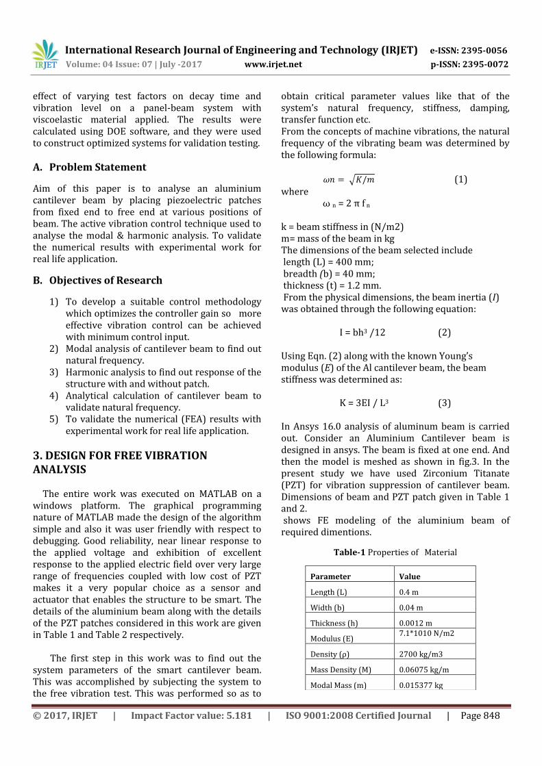
obtain critical parameter values like that of the system’s natural frequency, stiffness, damping, transfer function etc. From the concepts of machine vibrations, the natural frequency of the vibrating beam was determined by the following formula:
√ (1) where
ω n = 2 π f n k = beam stiffness in (N/m2) m= mass of the beam in kg The dimensions of the beam selected include length (L) = 400 mm; breadth (b) = 40 mm; thickness (t) = 1.2 mm. From the physical dimensions, the beam inertia (I) was obtained through the following equation:
I = bh3 /12 (2) Using Eqn. (2) along with the known Young’s modulus (E) of the Al cantilever beam, the beam stiffness was determined as:
K = 3EI / L3 (3) In Ansys 16.0 analysis of aluminum beam is carried out. Consider an Aluminium Cantilever beam is designed in ansys. The beam is fixed at one end. And then the model is meshed as shown in fig.3. In the present study we have used Zirconium Titanate (PZT) for vibration suppression of cantilever beam. Dimensions of beam and PZT patch given in Table 1 and 2. shows FE modeling of the aluminium beam of required dimentions.
Table-1 Properties of Material
Parameter Value
Length (L) 0.4 m
Width (b) 0.04 m
Thickness (h) 0.0012 m
Modulus (E) 7.1*1010 N/m2
Density (ρ) 2700 kg/m3
Mass Density (M) 0.06075 kg/m
Modal Mass (m) 0.015377 kg

International Research Journal of Engineering and Technology (IRJET) e-ISSN: 2395-0056
Volume: 04 Issue: 07 | July -2017 www.irjet.net p-ISSN: 2395-0072
© 2017, IRJET | Impact Factor value: 5.181 | ISO 9001:2008 Certified Journal | Page 849
Table-2. Properties of PZT Patches
Properties PZT-5H
Density 7350 kg/m3
Elastic Stiffness Matrix
C11 12.6 × 10¹⁰ N/m2
C12 7.95 × 10¹⁰ N/m2
C13 8.41 × 10¹⁰ N/m2
C33 11.7 × 10¹⁰ N/m2
C44 2.33 × 10¹⁰ N/m2
Piezoelectric Strain Matrix
E31 6.5 C/m2
E33 23.3 C/m2
E15 17 C/m2
Dielectric Matrix
ε11 1.503 × 10⁻⁸ F/m
ε22 1.503 × 10⁻⁸ F/m
ε33 1.503 × 10⁻⁸ F/m
Fig-1: Finite Element Model of Aluminium Beam
Fig-2: Aluminium Beam with One End Fixed
Fig-3: Meshed Model of beam
a. Modal analysis
In structural mechanics problems the modal analysis is used to find natural mode shape and frequency of an object during free vibration condition. It is common that the finite element method (FEM) to perform this analysis because, like other calculations using the FEM, the object being analyzed can have arbitrary shape and the results of the calculations are acceptable. The types of equations which obtained from modal analysis are those seen in Eigen systems. Following Fig 4, 5 and 6 shows first, second and third natural frequency of cantilever beam and corresponding stresses.
Fig-4: First Mode Shape of Beam
From above Fig.4 it is observed that first natural
frequency of aluminum beam is 7.64 Hz ≈ 8 Hz.

International Research Journal of Engineering and Technology (IRJET) e-ISSN: 2395-0056
Volume: 04 Issue: 07 | July -2017 www.irjet.net p-ISSN: 2395-0072
© 2017, IRJET | Impact Factor value: 5.181 | ISO 9001:2008 Certified Journal | Page 850
Fig-5: Second Mode Shape of Beam
From above Fig. 5 it is observed that second natural frequency of aluminum beam is 47.92 Hz ≈ 48 Hz.
Fig-6: Third Mode Shape of Beam
From above Fig. 6 it is observed that third natural frequency of aluminum beam is 132.44 Hz ≈ 133 Hz.
Table-3 Natural Frequency by Analytical and FEA
Approach
Analytical
Frequency
(Hz)
FEA
Frequency(Hz)
% Change of
Analytical Vs
FEA
7.58 7.65 -0.94%
47.48 47.90 -0.89%
132.96 132.44 0.39%
b. Patch Location from Modal analysis
Modal analysis of the beam is performed using first
mode shape of the beam as baseline model. Hereafter
for experimental analysis and finite element analysis,
we have considered first mode of vibration that is
first natural frequency (8 Hertz).
Now using modal analysis strain is maximum at fixed end for 8 Hertz. On the basis of strain concentration diagram shown below, Fig. 7 we locate patch at various locations. Initially patch is applied at fixed end, denoted as configuration as B1. Similarly patch is applied middle portion and free end of beam denotes as B2 and B3 respectively.
Fig-7: Maximum strain location for first mode shape
From above Fig. 8, it is observed that strain is maximum at fixed end of aluminum beam.
Based on above plot, initially patch is stacked on fixed end of beam.
Fig-8 : B1 Configuration

International Research Journal of Engineering and Technology (IRJET) e-ISSN: 2395-0056
Volume: 04 Issue: 07 | July -2017 www.irjet.net p-ISSN: 2395-0072
© 2017, IRJET | Impact Factor value: 5.181 | ISO 9001:2008 Certified Journal | Page 851
Max strain location for 2nd mode:
Fig-9: Mode shape B2
Fig-10: patch stick at middle
Based on above plot, Patch is stick on middle of beam.
Fig-11: Patch is stick at free end of beam.
Following Fig. shows analysis setup created for aluminum beam. A force of 0.1 N is applied at free end.
Fig-12: Analysis Set Up For Modal Analysis
c. Harmonic analysis for first natural frequency
In harmonic analysis effect of parameters shown in Table 4 on damping of the cantilever beam is studied.
Table-4 Variables for Study of Damping
Location of the
patch
Voltage (mV) Force (N)
B1 12 0.1
B2 12 0.1
B3 12 0.1
Now aluminum beam is actuated externally and harmonic analysis is carried out in FEA to calculate deflection at different location of the beam at first mode shape. Fig. 13 shows vibration response along length of the beam.

International Research Journal of Engineering and Technology (IRJET) e-ISSN: 2395-0056
Volume: 04 Issue: 07 | July -2017 www.irjet.net p-ISSN: 2395-0072
© 2017, IRJET | Impact Factor value: 5.181 | ISO 9001:2008 Certified Journal | Page 852
Fig-13: Vibration response of the beam at first mode
shape
Fig-14: Frequency response of the beam
Further PZT patch is bonded near the fixed end of the beam and 12 mV voltages is applied to it. Again harmonic analysis is carried out to study the damping caused because of PZT patch.
Analysis Set Up:
Force: 0.1 N
Voltage: 12mV
Following Fig. shows the analysis set up for FEA analysis.
Fig-15: Analysis Setup for Harmonic Analysis
When FEA analysis is carried out with mentioned analysis setup vibartion response is greatly reduced. Following Fig. shows the reduction after patch is applied with voltage.
Fig-16: Harmonic response with B1 Configuration with Voltage
Fig-17: Frequency response of the beam with B1
Configuration with Voltage

International Research Journal of Engineering and Technology (IRJET) e-ISSN: 2395-0056
Volume: 04 Issue: 07 | July -2017 www.irjet.net p-ISSN: 2395-0072
© 2017, IRJET | Impact Factor value: 5.181 | ISO 9001:2008 Certified Journal | Page 853
To evaluate the effciency of active vibration control over passive vibration control we carry out the passive vibration control using patch at free end without applying voltage. Fig. shows the vibration response of aluminum beam with passive vibration control.
Fig-18: Harmonic response of beam with B1 Configuration without voltage
Fig-19: Frequency response of beam with B2
configuration without Voltage
From above figures and values it is observed that
vibration reduction is better in case of active
vibration control as compared to passive vibration.
Therefore, active vibration control system is better
than passive vibration control system.
Now to find out the optimum location of PZT patch
we have applied the patch at middle of the beam and
at the free end of the beam. Fig. 20 and 21 shows the
harmonic response of the beam when patch is at the
middle.
Fig-20: Harmonic response of beam with B2 Configuration with voltage
Fig-21: Frequency response of beam with B2 Configuration with voltage
From figures and values it is cleared that vibration reduction is occurred more in case of the patch applied at fixed end than at middle of the beam.
Similarly, patch is applied at free end and active vibration control method is carried out. Fig. shows the vibration response of the beam when patch is applied at free end of the beam.

International Research Journal of Engineering and Technology (IRJET) e-ISSN: 2395-0056
Volume: 04 Issue: 07 | July -2017 www.irjet.net p-ISSN: 2395-0072
© 2017, IRJET | Impact Factor value: 5.181 | ISO 9001:2008 Certified Journal | Page 854
Fig-22: Frequency response of beam with B3 Configuration with voltage
From above values it can be concluded that maximum damping is achieved when patch is applied at fixed end.
d. Vibration response for various locations of PZT material Following Fig. shows the vibration response
of beam without patch, with patch at fixed end without voltage and patch at different location along the length of the beam. From the graph it is concluded that when patch is applied at different location then maximum damping is achieved when patch is applied at fixed end that is at maximum strain location. It also shows that active damping is more effective than passive damping.
Fig-23: Overall FEA Results
4. CONCLUSIONS
1. Cantilever beam natural frequency from FEA, Analytical & experimental is observed to be 8Hz & good correlation is observed (28-32% variation).
2. 2% variation is observed at excitation frequency for FEA wrt actual experimental with harmonic response.
3. Vibration amplitude reduction is observed after installing patch on fixed end of cantilever beam.
4. Vibration amplitude with patch installing @ fixed end is reduced by 66%. for 1st natural frequency.
REFERENCES [1] ZhiyuanGao, XiaojinZhu, YubinFang,
HeshengZhang, “Active monitoring and vibration control of smart structure aircraft based on FBG sensors and PZT actuators”, Aerospace Science and Technology, 2017, P.P.1-9.
[2] FengmingLi, ChuanzengZhang, ChunchuanLiu, “Active tuning of vibration and wave propagation in elastic beams with periodically placed piezoelectric actuator/sensor pairs”, Journal of Sound and Vibration, 2017, P.P.201-216.
[3] Sharvari S. Heganna∗ and Jayesh J. Joglekar,
“Active Vibration Control of Smart Structure using PZT Patches”, Twelfth International Multi-Conference on Information Processing-2016 (IMCIP-2016), Procedia Computer Science 89, 2016, 710 – 715.

International Research Journal of Engineering and Technology (IRJET) e-ISSN: 2395-0056
Volume: 04 Issue: 07 | July -2017 www.irjet.net p-ISSN: 2395-0072
© 2017, IRJET | Impact Factor value: 5.181 | ISO 9001:2008 Certified Journal | Page 855
[4] Harijono Djojodihardjo, Mohammad Jafari, Surjatin Wiriadidjaja, Kamarul Arifin Ahmad, “Active Vibration Suppression of an elastic piezoelectric sensor and actuator fitted cantilevered beam configurations as a generic smart composite structure”, Composite Structures 132, 2015, p.p.848–863.
BIOGRAPHIES
Mr. Shendre Lalit Rajendra , has 1 year of industrial experience. He is now pursuing Masters in Design Engineering in the department of Mechanical Engineering, SNDCOE & RC, Yeola affiliated to Savitribai Phule Pune University, Pune [email protected]
Prof. Bhamre V.G. is currently working as, Head, Department of Mechanical Engineering. SNDCOE & RC, Yeola affiliated to Savitribai Phule Pune University, Pune . He has total 17 years of teaching experience. He is now pursuing his PhD from G.H. Raisoni institute, Nagpur.
thor