the aim of the thesis is design of retina identification...
TRANSCRIPT

1
INTRODUCTION
Biometric recognition, or biometrics, refers to the automatic identification of a person based
on his/her anatomical (e.g. fingerprint, iris) or behavioural (e.g. signature) characteristics or
traits. This method of identification offers several advantages over traditional methods
involving ID cards (tokens) or PIN numbers (passwords) for various reasons: (i) the person to
be identified is required to be physically present at the point-of-identification; (ii)
identification based on biometric techniques obviates the need to remember a password or
carry a token. With the increased integration of computers and Internet into our everyday
lives, it is necessary to protect sensitive and personal data. By replacing PINs (or using
biometrics in addition to PINs), biometric techniques can potentially prevent unauthorized
access to ATMs, cellular phones, laptops, and computer networks. Unlike biometric traits,
PINs or passwords may be forgotten, and credentials like passports and driver's licenses may
be forged, stolen, or lost. As a result, biometric systems are being deployed to enhance
security and reduce financial fraud. Various biometric traits are being used for real-time
recognition, these are fingerprint recognition, facial recognition, iris recognition, hand
geometry recognition, palm print recognition, voice recognition, keystroke recognition,
signature recognition, speech recognition and retinal recognition. In some applications, more
than one biometric trait is used to attain higher security and to handle failure to
enroll situations for some users. Such systems are called Multimodal Biometric Systems.
Retinal identification (RI) is an automatic method that provides true identification of the
person by acquiring an internal body image, the retina/choroid of a willing person who must
cooperate in a way that would be difficult to counterfeit.
RI has found application in very high security environments (nuclear research and weapons
sites, communications control facilities and a very large transaction-processing center). The
installed base is a testament to the confidence in its accuracy and invulnerability. Its small
user base and lack of penetration into high-volume price sensitive applications is indicative of
its historically high price and its unfriendly perception.
The aim of the thesis is design of retina identification system using neural network. The
design of such system will allow to automate the personal identification using retina. The
thesis contains introduction, three chapters, conclusion, references and appendices.

2
Chapter 1 describes review on biometric identification using retinal images. The basic
biometric identification techniques are briefly described. The used methodologies are
described. Personal identification using retina have been described. State of art of neural
networks based retina identification is described.
Chapter 2 describes the anatomy and uniqueness of the retina. The physical characteristics of
retina, its structure and the functions are described briefly.
Chapter 3 describes neural network structure for retinal image identification. The Neural
Network structure for retina identification has been described. The learning algorithm of
Neural Network have been presented.
Chapter 4 describes the design of neural networks based retina recognition system. The
design algorithm has been described. Simulation of Neural Network based retina
identification system has been performed. Results of simulation of Retinal identification using
Neural Network have been discussed.
Conclusions include the important results obtained from the simulation of retinal
identification system.
References includes list of references used in the thesis.
Appendices include listing of program of retinal identification system using Neural Network.

3
CHAPTER 1
REVIEW ON BIOMETRIC IDENTIFICATION USING RETINAL IMAGES
1.1 An Overview of Biometric Recognition
A biometric system is essentially a pattern recognition system that operates by acquiring
biometric data from an individual, extracting a feature set from the acquired data, and
comparing this feature set against the template set in the database. Depending on the
application context, a biometric system may operate either in verification mode or
identification mode. In the verification mode, the system validates a person’s identity by
comparing the captured biometric data with her own biometric template(s) stored in the
system database.
In such a system, an individual who desires to be recognized claims an identity, usually via a
personal identification number (PIN), a user name, or a smart card, and the system conducts a
one-to-one comparison to determine whether the claim is true or not. Identity verification is
typically used for positive recognition, where the aim is to prevent multiple people from using
the same identity.
In the identification mode, the system recognizes an individual by searching the templates of
all the users in the database for a match. Therefore, the system conducts a one-to-many
comparison to establish an individual’s identity or fails if the subject is not enrolled in the
system database without the subject having to claim an identity. Identification is a critical
component in negative recognition applications where the system establishes whether the
person is who she implicitly or explicitly denies to be. The purpose of negative recognition is
to prevent a single person from using multiple identities [26]. Identification may also be used
in positive recognition for convenience the user is not required to claim an identity. While
traditional methods of personal recognition such as passwords, PINs, keys, and tokens may
work for positive recognition, negative recognition can only be established through
biometrics[7].

4
Biometrics is measurable biological (anatomical and behavioural) characteristics that can be
used for automated recognition. A biometric system is essentially a pattern recognition system
which recognizes a user by determining the authenticity of a specific anatomical or
behavioural characteristic possessed by the user. Several important issues must be considered
in designing a practical biometric system.
First, a user must be enrolled in the system so that his biometric template or reference can be
captured. This template is securely stored in a central database or a smart card issued to the
user. The template is used for matching when an individual needs to be identified. Depending
on the context, a biometric system can operate either in a verification (authentication) or an
identification mode.
Biometric recognition is a process in which a biometric system compares incoming
information which data in its system to determine whether or not it can find a match.
Biometric recognition, or biometrics, refers to the automatic identification of a person based
on his/her anatomical or behavioural characteristics or traits. This method of identification
offers several advantages over traditional methods involving ID cards or PIN numbers or
passwords for various reasons:
(i) the person to be identified is required to be physically present at the point-of-
identification
(ii) identification based on biometric techniques obviates the need to remember a
password or carry a token
(iii) With the increased integration of computers and Internet into our everyday lives, it
is necessary to protect sensitive and personal data. By replacing PINs (or using
biometrics in addition to PINs), biometric techniques can potentially prevent
unauthorized access to ATMs, cellular phones, laptops, and computer networks.
Unlike biometric traits, PINs or passwords may be forgotten, and credentials like
passports and driver's licenses may be forget, stolen, or lost. As a result, biometric
systems are being deployed to enhance security and reduce financial fraud.

5
Various biometric traits are being used for real-time recognition, the most popular being face,
iris and fingerprint. However, there are biometric systems that are based on retinal scan,
speech, voice, signature and hand geometry. In some applications, more than one biometric
trait is used to attain higher security and to handle failure to enroll situations for some users.
Such systems are called multimodal biometric systems.
The biometric technologies include fingerprint recognition, facial recognition, iris
recognition, hand geometry recognition, voice recognition, keystroke recognition, signature
recognition and retinal recognition. There does not appear to be any one method of biometric
data gathering and reading that does the "best" job of ensuring secure authentication. Each of
the different methods of biometric identification have something to recommend them. Some
are less invasive, some can be done without the knowledge of the subject, some are very
difficult to fake.
Face Recognition
Face recognition is the size and shape of facial characteristics and their relationships to each
other. Facial Recognition is one of the most flexible, working even when the subject is
unaware of being scanned. It also shows promise as a way to search through masses of people
who spent only seconds in front of a "scanner" - that is, an ordinary digital camera. Face
recognition systems work by systematically analyzing specific features that are common to
everyone's face - the distance between the eyes, width of the nose, position of cheekbones,
jaw line, chin and so forth. These numerical quantities are then combined in a single code that
uniquely identifies each person.
Fig. 1.1 Face Recognition [55]

6
Fingerprint Identification
Fingerprints remain constant throughout life. In over 140 years of fingerprint comparison
worldwide, no two fingerprints have ever been found to be alike, not even those of identical
twins. Good fingerprint scanners have been installed in PDAs like the iPaq Pocket PC; so
scanner technology is also easy. Might not work in industrial applications since it requires
clean hands. Fingerprint identification involves comparing the pattern of ridges and furrows
on the fingertips, as well as the minutiae points (ridge characteristics that occur when a ridge
splits into two, or ends) of a specimen print with a database of prints on file.
Fig.1.2 Fingerprint Identification [56]
Hand Geometry Biometrics
A variety of measurements of the human hand, including its shape, and lengths and widths of
the fingers can be used as biometric characteristics[13]. Hand geometry readers work in harsh
environments, do not require clean conditions, and forms a very small dataset. It is not
regarded as an intrusive kind of test. It is often the authentication method of choice in
industrial environments.

7
Retinal Scan
There is no known way to replicate a retina. As far as anyone knows, the pattern of the blood
vessels at the back of the eye is unique and stays the same for a lifetime. However, it requires
about 15 seconds of careful concentration to take a good scan. Retina scan remains a standard
in military and government installations.
Fig. 1.3 Retinal Scan [59]
Iris Scan
Like a retina scan, an iris scan also provides unique biometric data that is very difficult to
duplicate and remains the same for a lifetime. The scan is similarly difficult to make (may be
difficult for children or the infirm). However, there are ways of encoding the iris scan
biometric data in a way that it can be carried around securely in a "barcode" format. (See the
SF in the News article Biometric Identification Finally Gets Started for some detailed
information about how to perform an iris scan.)
Fig. 1.4 Iris Scan [57]

8
Signature Identification
Each person has a unique style of hand-writing. However, no two signatures of a person are
exactly identical; the variations from a typical signature also depend upon the physical and
emotional state of a person. The identification accuracy of systems based on this highly
behavioural biometric is reasonable but does not appear to be sufficiently high to lead to
large-scale recognition. There are two approaches to identification based on signature[14]:
Static and Dynamic. Static signature identification uses only the geometric (shape) features of
a signature, whereas dynamic (online) signature identification uses only both the geometric
(shape) features and the dynamic features such as acceleration, velocity, pressure, and
trajectory profiles of the signature. An inherent advantage of a signature-based biometric
system is that the signature has been established as an acceptable form of personal
identification method and can be incorporated transparently into the existing business
processes requiring signatures such as credit card transactions. A signature is another example
of biometric data that is easy to gather and is not physically intrusive. Digitized signatures are
sometimes used, but usually have insufficient resolution to ensure authentication.
Speech Recognition
Speech is a predominantly behavioural biometrics. The invariance in the individual
characteristics of human speech is primarily due to relatively invariant shape/size of the
appendages (vocal tracts, mouth, nasal cavities, lips) synthesizing the sound[15]. Speech of a
person is distinctive but may not contain sufficient invariant information to offer large-scale
recognition. Speech-based verification could be based on either a text-dependent or a text-
independent speech input. A text-dependent verification authenticates the identity of an
individual based on the utterance of a fixed predetermined phrase. A text-independent
verification verifies the identity of a speaker independent of the phrase, which is more
difficult than a text-dependent verification but offers more protection against fraud. Generally,
people are willing to accept a speech-based biometric system. However, speech-based
features are sensitive to a number of factors such as background noise as well as the
emotional and physical state of the speaker. Speech-based authentication is currently
restricted to low-security applications because of high variability in an individual’s voice and
poor accuracy performance of a typical speech-based authentication system[17].

9
Voice Recognition
Voice is a combination of physiological and behavioural biometrics. The features of an
individual’s voice are based on the shape and size of the appendages (e.g., vocal tracts,
mouth, nasal cavities, and lips) that are used in the synthesis of the sound. These
physiological characteristics of human speech are invariant for an individual, but the
behavioural part of the speech of a person changes over time due to age, medical conditions
(such as a common cold),and emotional state, etc. Voice is also not very distinctive and may
not be appropriate for large-scale identification. A text-dependent voice recognition system is
based on the utterance of a fixed predetermined phrase. A text-independent voice recognition
system recognizes the speaker independent of what she speaks. A text-independent system is
more difficult to design than a text-dependent system but offers more protection against fraud.
A disadvantage of voice-based recognition is that speech features are sensitive to a number of
factors such as background noise. Speaker recognition is most appropriate in phone-based
applications but the voice signal over phone is typically degraded in quality by the
microphone and the communication channel.
There are two different ways to recognize a person: verification and identification.
Verification (Am I who I claim I am?) involves confirming or denying a person's claimed
identity. On the other hand, in identification, the system has to recognize a person (Who am
I?) from a list of N users in the template database. Identification is a more challenging
problem because it involves 1:N matching compared to 1:1 matching for verification.
While biometric systems has been widely used in forensics for criminal identification,
progress in biometric sensors and matching algorithms have led to the deployment of
biometric authentication in a large number of civilian and government applications.
Biometrics is being used for physical access control, computer log-in, welfare disbursement,
international border crossing and national ID cards. It can be used to verify a customer during
transactions conducted via telephone and Internet (electronic commerce and electronic
banking). In automobiles, biometrics is being adopted to replace keys for keyless entry and
keyless ignition. Due to increased security threats, the ICAO (International Civil Aviation
Organization) has approved the use of e-passports (passports with an embedded chip
containing the holder's facial image and other traits).

10
1.2 Retina and Iris Identification
1.2.1 Iris recognition
Iris recognition today combines technologies from several fields including, computer vision
(CV), pattern recognition, statistical interference, and optics. The goal of the technology is
near-instant, highly accurate recognition of a person's identity based on a digitally represented
image of the scanned eye. The technology is based upon the fact that no two iris patterns are
alike (the probability is higher than that of fingerprints). The iris is a protected organ which
makes the identification possibilities life long. The iris can therefore serve as a life long
password which the person must never remember. Confidence in recognition and
identification facilitates exhustive searches through nation-sized databases.
Iris recognition technology looks at the unique characteristics of the iris, the coloured area
surrounding the pupil. While most biometrics have 13 to 60 distinct characteristics, the iris is
said to have 266 unique spots. Each eye is believed to be unique and remain stable over time
and across environments.
Iris recognition systems use small, high-quality cameras to capture a black and white high-
resolution photograph of the iris. Once the image is captured, the iris' elastic connective
tissue-called the trabecular meshwork-is analyzed, processed into an optical "fingerprint," and
translated into a digital form. Figure 12 depicts the process of generating an iris biometric.
Given the stable physical traits of the iris, this technology is considered to be one of the safest,
fastest, and most accurate, non invasive biometric technologies. This type of biometric
scanning works with glasses and contact lenses in place.
Therefore, iris scan biometrics may be more useful for higher risk interactions, such as
building access. Improvements in ease of use and system integration are expected as new
products are brought to market.
The iris is differentiated by several characteristics including ligaments, furrows, ridges,
crypts, rings, corona, freckles, and a sigzag collarette.

11
Fig. 1.5 Iris Identification [58]
Iris recognition technologies are now seen in a wide array of identification systems. They are
used in passports, aviation security, access security (both physical and electronic), hospitals,
and national watch lists. Iris recognition algorithms can be seen in more and more
identification systems relating to customs and immigration. Future applications will include,
e-commerce, information security (infosec), authorisation, building entry, automobile
ignition, forensic applications, computer network access, PINs, and personal passwords.
Advantages of the Iris for Identification:
Highly protected, internal organ of the eye
Externally visible; patterns imaged from a distance
Iris patterns possess a high degree of randomness
variability: 244 degrees-of-freedom
entropy: 3.2 bits per square-millimeter
uniqueness: set by combinatorial complexity
Changing pupil size confirms natural physiology
Pre-natal morphogenesis (7th month of gestation)
Limited genetic penetrance of iris patterns
Patterns apparently stable throughout life
Encoding and decision-making are tractable
image analysis and encoding time: 1 second
decidability index (d-prime): d' = 7.3 to 11.4
search speed: 100,000 IrisCodes per second on 300MHz CPU

12
Disadvantages of the Iris for Identification:
Small target (1 cm) to acquire from a distance (1 m)
Moving target ...within another... on yet another
Located behind a curved, wet, reflecting surface
Obscured by eyelashes, lenses, reflections
Partially occluded by eyelids, often drooping
Deforms non-elastically as pupil changes size
Illumination should not be visible or bright
Some negative (Orwellian) connotations
1.2.2 Retina recognition
Retina recognition technology captures and analyzes the patterns of blood vessels on the thin
nerve on the back of the eyeball that processes light entering through the pupil. Retinal
patterns are highly distinctive traits. Every eye has its own totally unique pattern of blood
vessels; even the eyes of identical twins are distinct. Although each pattern normally remains
stable over a person's lifetime, it can be affected by disease such as glaucoma, diabetes, high
blood pressure, and autoimmune deficiency syndrome.
The fact that the retina is small, internal, and difficult to measure makes capturing its image
more difficult than most biometric technologies. An individual must position the eye very
close to the lens of the retina-scan device, gaze directly into the lens, and remain perfectly still
while focusing on a revolving light while a small camera scans the retina through the pupil.
Any movement can interfere with the process and can require restarting. Enrollment can
easily take more than a minute. The generated template is only 96 bytes, one of the smallest of
the biometric technologies.
One of the most accurate and most reliable of the biometric technologies, it is used for access
control in government and military environments that require very high security, such as
nuclear weapons and research sites. However, the great degree of effort and cooperation
required of users has made it one of the least deployed of all the biometric technologies.
Newer, faster, better retina recognition technologies are being developed.

13
1.3 State of Art of Retinal Identification
Research on biometrics based on retinal vascular patterns has been limited for the most part to
applications directly related to the medical realm, and here primarily on image registration
and subsequent detection of vascular patterns.
The registration process itself can be feature-based or area-based. In the latter case, pixel
intensities of the retinal image are used in objective functions based on statistical properties
such as cross-correlation, phase correlation, or error values. For feature-based registration, the
process is similar to that used in manual registration by matching characteristic high-contrast
or point entities using a similarity measure and may also use geometric features such as
bifurcations and angles in vascular patterns to achieve matching.
Moreover, hybrid approaches have also been proposed for use in both diagnostic and
registration applications. For example, Chanwimaluang et al. discuss retinal image
registration for use in the detection of diabetic retinopathy.
Based on the hypotheses posited by Simon and Goldstein, the applications for the biometric
identification and verification of identities were examined by Hill, initially using fundus
cameras commonly used in opthalmological applications.
While these cameras yielded high-quality images, they were uneconomical and, more
importantly, produced discomfort in subjects since the illumination was deemed too bright.
Subsequent developments in commercial research and development was based on
illumination by means of infrared light to circumvent the abovementioned difficulties.
In addition to these usability aspects, however, infrared lighting has the advantage of being
absorbed at a different rate by the vascular system than surrounding tissue, enhancing the
contrast produced for both the retinal and choroidal vascular.

14
Retina is used to recognize a person. The fact that blood vessels have vessels with different
thickness and width motivate us to analyze the retina using multi-resolution analysis method.
A novel retina feature, named wavelet energy feature (WEF) is defined in the paper,
employing wavelet, which is a powerful tool of multi-resolution analysis.
WEF can reflect the wavelet energy distribution of the vessels with different thickness and
width in several directions at different wavelet decomposition levels (scales), so its ability to
discriminate retinas is very strong. Easiness to compute is another virtue of WEF. Using semi-
conductors and various environmental temperatures in electronic imaging systems cause noisy
images, so in this article noisy retinal images are used in recognition. In existence of 5db to
20db noise the proposed method can achieve %100 recognition rates [1].
While retina recognition is recognized as a highly accurate and difficult to forge biometric, it
has not seen widespread acceptance. In addition to user acceptance of what is at times
considered an invasive technique, this limited acceptance was caused in part by the relatively
high cost of signal acquisition. To alleviate the latter concern, this paper therefore describes a
retina recognition algorithm based on Hill’s algorithm together with a description of its
implementation and experimental evaluation. The algorithm is designed to operate with
signals acquired in the visual spectrum, which can be obtained using a number of off-the-shelf
camera systems and provides acceptable performance compared to approaches based on near-
infrared retinal images [2].
Hybrid biometric system two biometrics can be taken from the same acquisition process and
image. Gabor transform to extract the features from Iris and Retina is used and also
geometrical features extraction steps of retina image is processed. Feature fusion is performed
[3].
Biometrics are used for personal recognition based on some physiologic or behavioral
characteristics. In this era, biometric security systems are widely used which mostly include
fingerprint recognition, face recognition, iris and speech recognition etc. Retinal recognition
based security systems are very rare due to retina acquisition problem but still it provides the
most reliable and stable mean of biometric identification.

15
This paper presents a four stage personal identification system using vascular pattern of
human retina. In first step, it acquires and pre processes the coloured retinal image. Then
blood vessels are enhanced and extracted using 2-D wavelet and adaptive thresholding
respectively. In third stage, it performs feature extraction and filtration followed by vascular
pattern matching in forth step. The proposed method is tested on three publicly available
databases i.e DRIVE, STARE and VARIA. Experimental results show that the proposed
method achieved an accuracy of 0.9485 and 0.9761 for vascular pattern extraction and
personal recognition respectively [4].
The characteristics of human body such as fingerprint, face, hand palm and iris are measured,
recorded and identified by performing comparison using biometric devices. Even though it
has not seen widespread acceptance yet, retinal identification based on retinal vasculatures in
retina provides the most secure and accurate authentication means among biometric systems.
Using retinal images taken from individuals, retinal identification is employed in
environments such as nuclear research centers and facilities, weapon factories, where
extremely high security measures are needed. The superiority of this method stems from the
fact that retina is unique to every human being and it would not be changed during human
life. Adversely, other identification approaches such as fingerprint, face, palm and iris
recognition, are all vulnerable in that those characteristics can be corrupted via plastic
surgeries and other changes. In this study we propose an alternate personal identification
system based on retinal vascular network in retinal images, which tolerates scale, rotation and
translation in comparison. In order to accurately identify a person our new approach first
segments vessel structure and then employ similarity measurement along with the tolerations.
The developed system, tested on about four hundred images, presents over 95% of success
which is quite promising [5].
Retina based identification is perceived as the most secure method of authenticating an
identity. This chapter traces the basis of retina based identification and overviews evolution of
retina based identification technology. It presents details of the innovations involved in
overcoming the challenges related to imaging retina and user interface. The retinal
information used for distinguishing individuals and a processing method for extracting an
invariant representation of such information from an image of retina are also discussed.

16
The issues involved in verifying and identifying an individual identity are presented. The
chapter describes performance of retina based identification and the source of inaccuracies
thereof. The limitations of the retina based technology are enumerated. Finally, the chapter
attempts to speculate on the future of the technology and potential applications [6].
In order to assure effective traceability, food-producing animals must be identified by a
tamper-proof and durable technique. With the advance in human biometric technologies, the
deployment of retinal recognition technology for cattle identification and verification has been
prompted. The objective of this study was to assess the accuracy of a commercially available
retina biometric technology for sheep identification (i) by determining whether light
conditions during retinal image capture and different operators exerted any significant effect
on the matching score of the built-in pattern matching algorithm; and (ii) by evaluating the
recognition performance of the biometric system for enrolment of one retinal image per sheep
and two retinal images per sheep (bimodal biometric system). Neither the light conditions nor
the operators were found to have a statistically significant effect on the matching score values
of the built-in algorithm; yet it was clear that the pupillary light reflex phenomenon played a
major role in obtaining lower matching score values for retinal images taken outdoors. The
recognition errors of the one-retina biometric system were estimated to be 0.25% for false
matches and 0.82% for false non-matches. An improved bimodal biometric system, i.e., two
retinas, that applies a decision criterion based on a simple OR logical operator and a sum of
matching scores, has been proposed in this study in order to reduce both probabilities of false
matches and false non-matches to near zero [11].
Novel retinal identification system is composed of three principal modules including blood
vessel segmentation, feature generation, and feature matching. Blood vessel segmentation
module has the role of extracting blood vessels pattern from retinal images. Feature
generation module includes the following stages. First, the optical disk is found and a circular
region of interest (ROI) around it is selected in the segmented image. Then, using a polar
transformation, a rotation invariant template is created from each ROI.

17
In the next stage, these templates are analyzed in three different scales using wavelet
transform to separate vessels according to their diameter sizes. In the last stage, vessels
position and orientation in each scale are used to define a feature vector for each subject in the
database. For feature matching, we introduce a modified correlation measure to obtain a
similarity index for each scale of the feature vector. Then, we compute the total value of the
similarity index by summing scale-weighted similarity indices. Experimental results on a
database, including 300 retinal images obtained from 60 subjects, demonstrated an average
equal error rate equal to 1 percent for our identification system [12].

18
CHAPTER TWO
THE ANATOMY AND THE UNIQUENESS OF THE RETINA
2.1.The Anatomy
The retina is the light-sensitive membrane on the inside back of the eye that converts the
image focused on it into neural impulses that travel along the optic nerve to the brain to create
sight. The retina itself is made up of several layers, those most toward the back of the eye
contain the rods and cones which are responsible of our black and white and colour vision
respectively. Additional layers contain Horizontal, Bipolar, Amacrine and Ganglion cells that
combine the impulses of the individual rods and cones before they travel along the optic nerve
fibers to the brain.
Figure 2.1 shows a side view of the eye - the iris is located in the front of the eye, while the
retina is located at the back. Because of its position within the eye, the retina is not exposed to
the external environment. As a biometric, it is therefore very stable.
Fig. 2.1 Side View of the Eye

19
Figure 2.2 shows a front view of the blood vessel pattern within the retina. The red lines
represent the actual blood vessels; the yellow section indicates the position of the optic disc
(the place where the optic nerve joins the retina). It is from here that information is
transmitted to and received from the brain. The circle in the diagram indicates the area that is
typically captured by a retinal scanning device. It contains a unique pattern of blood vessels.
Fig. 2.2 Front View of the Blood Vessel Pattern within the Retina
There are two famous studies that have confirmed the uniqueness of the blood vessel pattern
found in the retina. The first was published by Dr Carleton Simon and Dr Isodore Goldstein in
1935, and describes how every retina contains a unique blood vessel pattern. The photographs
of these patterns as a means of identification. The second study was conducted in the 1950s
by Dr Paul Tower. He discovered that - even among identical twins - the blood vessel patterns
of the retina are unique and different[13].

20
Figure 2.3 (a) and (b) shows detail structure of retina [60] [61].
(a)
(b)
Fig. 2.3 Anatomy of Retina .

21
The macula is at the very center of the retina (Fig.3.4). It contains the highest concentration
of cones which provide both colour and detail vision. The macula is “ground zero”(Fig.3.5).
When we look at things we look with our macula. The macula represents the central 10
degrees of one’s visual field (of almost 180 degrees diameter) and is the part of the retina that
provides our 20/20 vision. As we move further away from the macula, the remaining retina,
even when healthy, does not provide the clear, detail vision that we are accustomed to using.
In fact, 10 degrees from the center of the macula, even healthy eyes are only capable of seeing
about 20/100.
Fig. 2.4 Macula of Retina

22
Fig. 2.5 Center of Macula Degrees from Fovea
As we go more peripherally on the retina, the concentration of cones decreases while the
concentration of rods increases. The rods work most well in low light and are most sensitive
to motion rather than detail.
In macular degeneration, it is only the macular area of the retina that is affected, leaving the
peripheral retina normal. However since the peripheral retina largely has rods it does not
provide the sharp detail nor normal colour vision. But, since the peripheral retina remains
intact, vision for walking and seeing general shapes is not lost.
Dry Age-Related Macular Degeneration (Dry AMD) occurs when the light-sensitive cells in
the macula slowly break down, gradually blurring central vision in the affected eye. As Dry
Age-Related Macular Degeneration (Dry AMD) gets worse, you may see a blurred spot in the
center of your vision. Over time, as less of the macula functions, central vision is gradually
lost in the affected eye.

23
The most common symptom of Dry Age-Related Macular Degeneration (Dry AMD) is
slightly blurred vision. You may have difficulty recognizing faces. You may need more light
for reading and other tasks. Dry Age-Related Macular Degeneration (Dry AMD) generally
affects both eyes, but vision can be lost in one eye while the other eye seems unaffected.
Fig. 2.6 Dry Macular Degeneration
Drusen, is the one of the most common early signs of Age-Related Macular Degeneration.
Drusen are yellow deposits under the retina. They often are found in people over age 60.
Drusen alone do not usually cause vision loss. In fact, scientists are unclear about the
connection between drusen and Age-Related Macular Degeneration. They do know that an
increase in the size or number of drusen raises a person's risk of developing either advanced
Dry Age-Related Macular Degeneration (Dry AMD) or Wet Age-Related Macular
Degeneration (Wet AMD).
Fig. 2.7 Macular Drusen

24
Wet Age-Related Macular Degeneration (Wet AMD), occurs when abnormal blood vessels
under the retina start to grow beneath the macula. These new blood vessels tend to be very
fragile and often leak blood and fluid. The blood and fluid raise the macula from its normal
place at the back of the eye damaging the macula, often rapidly.
Fig.2.8 Wet AMD
Retinitis Pigmentosa, on the other hand, is a disorder of the rods, so that night vision and the
ability to see to the side (Tunnel Vision) are reduced. Macular vision can remain near normal
so often individuals with Retinitis Pigmentosa can read and walk in bright sunlight. Devices
that expand the visual field (Image Minifiers and Field Viewers) can help individuals with
“Tunnel Vision” see more to the side, helping with mobility and other activities.
Fig. 2.9 Retinitis Pigmentosa

25
The iris and the retina are categorised as ‘eye biometrics’. Their respective functions are
completely different. The iris is the coloured region between the pupil and the white of the
eye (also known as the sclera). The primary purpose of the iris is to dilate and constrict the
size of the pupil. In this sense, the iris is analogous with the aperture of a camera.
It is said that the retina “is to the eye as film is to a camera.”The retina consists of multiple
layers of sensory tissue and millions of photoreceptors whose function is to transform light
rays into electrical impulses. These impulses subsequently travel to the brain via the optic
nerve, where they are converted to images. Two distinct types of photoreceptors exist within
the retina: the rods and the cones. While the cones (of which each eye contains approximately
6 million) help us to see different colours, the rods (which number 125 million per eye)
facilitate night and peripheral vision. It is the blood vessel pattern in the retina that forms the
foundation for retinal recognition as a science and technology.
2.2. Retina/Choroid as Human Descriptor
Retina detects incident light in the form of an image focused by a lens. It is an internal part of
the eye. Blood comes through vessels over the optical nerve. The choroid lies between the
retina and sclera. It is composed of blood vessels that nourish the back of the eye. The choroid
connects with the ciliary body toward the front of the eye and is attached to edges of the optic
nerve at the back of the eye.
Awareness of the uniqueness of the retinal vascular pattern dates back to 1935 when two
ophthalmologists, Drs. Carleton Simon and Isodore Goldstein, while studying eye disease,
made a startling discovery: every eye has its own totally unique pattern of blood vessels. They
subsequently published a paper on the use of retinal photographs for identifying people based
on blood vessel patterns [6].

26
Later in the 1950's, their conclusions were supported by Dr. Paul Tower in the course of his
study of identical twins [6]. He noted that, of any two persons, identical twins would be the
most likely to have similar retinal vascular patterns. However, Tower's study showed that of
all the factors compared between twins, retinal vascular patterns showed the least similarity.
The eye shares the same stable environment as the brain and among physical features unique
to individuals, none is more stable than the retinal vascular pattern. Because of its internal
location, the retina/choroid is protected from variations caused by exposure to the external
environment (as in the case of fingerprints, palm prints etc.).
Fig. 2.10 Eye and Scan Circle [9]
Referring to Figure 2.10, the retina is to the eye as film is to camera. Both detect incident light
in the form of an image that is focused by a lens. The amount of light reaching the retina (or
film) is a function of the iris (f-stop). The retina is located on the back inside of the eyeball.
Blood reaches the retina through vessels that come from the optic nerve. Just behind the retina
is a matting of vessels called the choroidal vasculature.
The products of EyeDentify, Inc. have always used infrared light to illuminate the retina as
will be discussed later. The retina is essentially transparent to this wavelength of light. The
mat of vessels of the choroid just behind the retina reflect most of the useful information used
to identify individuals, so the term “retinal identification” is a bit of a misnomer but
nevertheless useful because the term is familiar. RI in this chapter will be used
interchangeably to mean retina/choroid identification. This area of the eye is also referred to
by medical doctors as the eye fundus.

27
It might seem that corrective error changes (such as becoming more near-sighted over time)
might change the image of this very stable structure. In fact, the low resolution required to
acquire adequate identification information masks any effect the focus errors might have.
The RI products of EyeDentify, Inc. take advantage of this fact. No focusing of the RI system
optics is necessary reducing cost and making the unit easier to use.
The operational rule-of-thumb for the circular scan RI systems described here is as follows: If
the person to be identified can see well enough to drive with at least one eye, it is highly
likely that he/she can use RI successfully.
Children as young as four years of age have been taught how to use RI. Once learned, RI is
simple to use for the vast majority of the human population.
2.3. The Technology Behind Retinal RecognitionThe first company to become involved in the research, development and manufacture of
retinal scanning devices was EyeDentify Inc. The company was established in 1976 and its
first retina capturing devices were known as ‘fundus cameras’. While intended for use by
opthamologists, modified versions of the camera were used to obtain retina images. The
device had several shortcomings, however. First, the equipment was considered very
expensive and difficult to operate. Second, the light used to illuminate the retina was
considered too bright and too discomforting for the user.
Further research and development yielded the first true prototype scanning device, which was
unveiled in 1981. The device used infrared light to illuminate the blood vessel pattern of the
retina. The advantage of infrared light is that the blood vessel pattern in the retina can
‘absorb’ such light much faster than other parts of the eye tissue.

28
The reflected light is subsequently captured by the scanning device for processing. In addition
to a scanner, several algorithms were developed for the extraction of unique features. Further
research and development gave birth to the first true retinal scanning device to reach the
market: the EyeDentification System 7.5. The device utilised a complex system of scanning
optics, mirrors, and targeting systems to capture the blood vessel pattern of the retina.
Ongoing development resulted in devices with much simpler designs. Later scanners
consisted of integrated retinal scanning optics, which sharply reduced manufacturing costs
(compared to the EyeDentification System 7.5.).
The last retinal scanner to be manufactured by EyeDentify was the ICAM 2001, a device
capable of storing up to 3,000 templates and 3,300 transactions. The product was eventually
withdrawn from the market on account of its price as well as user concerns. As far as the
author is aware, only a single company is currently in the process of creating a retinal
scanning device: Retinal Technologies, LLC. It is believed that the company is working on a
prototype device that will be much easier to implement in commercial applications. It will
also be much more user friendly. Based on a scientific study whitepaper written by Retinal
Technologies, it appears that the methods used for testing their device reveal “huge
potential.”2
2.4 Causes of Problems (errors) and Biometric Performance Standards
As is the case with other biometric technologies, the performance of the retinal scanning
device may be affected by a number of variables, which could prevent an accurate scan from
being captured. Poor quality scans may be attributable to:
1. Lack of cooperation on the part of the user - as indicated, the user must remain very still
throughout the entire process, especially when the image is being acquired. Any movement
can seriously affect lens alignment.
2. The distance between the eye and the lens is incorrect and/or fluctuates - for a high quality
scan to be captured, the user must place his or her eye in very close proximity to the lens. In
this sense, iris scanning technology is much more user friendly; a quality scan can be captured
at a distance of up to three feet from the lens.
3. A dirty lens on the retinal scanning device. This will obviously interfere with the scanning
process.
4. Other types of light interference from an external source.

29
All biometric technologies are rated against a set of performance standards. As far as retinal
recognition is concerned, there are two performance standards: the False Reject Rate, and the
Ability To Verify Rate. Both are described below.
2.5The Strengths and Weaknesses of Retinal Recognition
Describes the probability of a legitimate user being denied authorisation by the retinal scanning system. Retinal recognition is most affected by the False Reject Rate. This is because the factors described above have a tangible impact on the quality of the retinal scan, causing a legitimate user to be rejected. Describes the probability of an entire user group being verified on a
given day. For retinal recognition, the relevant percentage has been as low as 85%. This is
primarily attributable to user-related concerns and the need to place one’s eye in very close
proximity to the scanner lens.
The strengths and weaknesses of retinal recognition just like all other biometric technologies,
retinal recognition has its own unique strengths and weaknesses. The strengths may be
summed up as follows:
1. The blood vessel pattern of the retina rarely changes during a person’s life (unless he or she
is afflicted by an eye disease such as glaucoma, cataracts, etc).
2. The size of the actual template is only 96 bytes, which is very small by any standards. In
turn, verification and identification processing times are much shorter than they are for larger
files.
3. The rich, unique structure of the blood vessel pattern of the retina allows up to 400 data
points to be created.
4. As the retina is located inside the eye, it is not exposed to (threats posed by) the external
environment. For other biometrics, such as fingerprints, hand geometry, etc., the opposite
holds true.

30
The most relevant weaknesses of retinal recognition are:
1. The public perceives retinal scanning to be a health threat; some people believe that a
retinal scan damages the eye.
2. User unease about the need to position the eye in such close proximity of the scanner lens.
3. User motivation: of all biometric technologies, successful retinal scanning demands the
highest level of user motivation and patience.
4. Retinal scanning technology cannot accommodate people wearing glasses (which must be
removed prior to scanning).
5. At this stage, retinal scanning devices are very expensive to procure and implement.
2.6 Retinal Recognition Applications
As retinal recognition systems are user invasive as well as expensive to install and maintain,
retinal recognition has not been as widely deployed as other biometric technologies
(particularly fingerprint recognition, hand geometry recognition, facial recognition, and, to
some extent, iris recognition).
To date, retinal recognition has primarily been used in combination with access control
systems at high security facilities. This includes military installations, nuclear facilities, and
laboratories. One of the best-documented applications involves the State of Illinois, which
used retinal recognition to reduce welfare fraud by identifying welfare recipients (thus
preventing multiple benefit payments). This project also made use of fingerprint recognition.
Retinal recognition was first introduced in Granite City and East Alton (southern Illinois)
towards mid-1996.
One of disadvantages of retina recognition is: retinal scanning is not client or staff friendly
and requires considerable time to secure biometric records. The literature review shows that
the researches on retina recognition have been continuing. In the thesis the artificial
intelligence technique is applied for recognition of retinal images.

31
2.7 Summary
The anatomy of retina is introduced. In view of the rich and unique blood vessel patterns in
the retina, there is no doubt that retinal recognition is the ‘ultimate’ biometric. Its high cost
and user-related drawbacks have prevented it from making a commercial impact. However, as
technology continues to advance, it seems likely that retinal recognition will one day be
widely accepted and used.

32
CHAPTER 3
NEURAL NETWORK STRUCTURE FOR RETINAL IMAGE IDENTIFICATION
3.1 Overview
In this chapter neural network based system used for retina recognition has been described.
The structure of neural networks and their learning algorithm have been described. The
learning of neural network based retina recognition system using back-propogation algorithms
described.
3.2 Processing
A neural network is a powerful data modelling tool that is able to capture and represent
complex input/output relationships. Neural Network is a mathematical model inspired by
biological neural network. A neural network consist of an interconnected group of artificial
neurons, and it processes information using a connectionist approach to computation. In most
cases a neural network is an adaptive system that changes its structure during a learning
phase. Neural networks are used to model complex relationships between input and output or
to find patterns in data.
Neural networks resemble the human brain in the following two ways:
A neural network acquires knowledge through learning.
A neural network's knowledge is stored within inter-neuron connection strengths known
as synaptic weights.
Artificial Neural Networks are indeed self learning mechanisms which don't require the
traditional skills of a programmer. Neural networks are a set of neurons connected together in
some manner. These neurons can contain separate transfer functions and have individual
weights and biases to determine an output value based on the inputs. An example of a basic

33
linear neuron can be thought of as a function which takes several inputs, multiplies each by its
respective weight, adds an overall bias and outputs the result.
Other types of neurons exist and there are many methods with which to train a neural
network. Training implies modifying the weights and bias of each neuron until an acceptable
output goal is reached. During training, if the output is far from its desired target, the weights
and biases are changed to help achieve a lower error.
A biological neural network is composed of a group or groups of chemically connected or
functionally associated neurons. A single neuron may be connected to many other neurons
and the total number of neurons and connections in a network may be extensive.
Connections, called synapses, are usually formed from axons to dendrites, though dendro
dendritic microcircuits and other connections are possible. Apart from the electrical
signalling, there are other forms of signalling that arise from neurotransmitter diffusion,
which have an effect on electrical signalling. As such, neural networks are extremely
complex.
3.3 Neural Network Architecture
The basic unit of neural networks, the artificial neurons (Figure 3.1), simulates the four basic
functions of natural neurons. Artificial neurons are much simpler than the biological neuron;
the figure below shows the basics of an artificial neuron.

34
Fig. 3.1 Artificial Neuron
Note that various inputs to the network are represented by the mathematical symbol, x(n).
Each of these inputs are multiplied by a connection weight, these weights are represented by
w(n). In the simplest case, these products are simply summed, fed through a transfer function
to generate a result, and then output.
A single-layer network of S neurons is shown in Figure 3.2. Note that each of the R inputs is
connected to each of the neurons and that the weight matrix now has R rows.
Input : Layer of Neurons
a=f (Wp+b)
Fig. 3.2 Layers of S Neurons

35
Where R is the number of elements in input vector, S is the number of neurons in layer. Each
element of the input vector P is connected to each neuron through the weight matrix W. Each
neuron has a bias bi, a summer, a transfer function f and an output ai. Taken together, the
outputs form the output vector a, the input vector elements enter the network through the
weight matrix W:
w1,1 w1,2 . . . w1,R
W = w2,1 w2,2 . . . w2,R
wS,1 wS,2 . . . wS,R
The S-neuron, R-input, one-layer network also can be drawn in abbreviated notation, as
shown in Figure 3.3.
Fig. 3.3 Layers of S Neurons, Abbreviated Notation
Here again, the symbols below the variables tell you that for this layer, P is a vector of length
R, W is a matrix, a and b are vectors of length S. The layer includes the weight matrix, the
summation and multiplication operations, the bias vector b, the transfer function boxes and
the output vector.
3.3.1 Multiple Layers of Neurons
Now consider a network with several layers. Each layer has its own weight matrix W, its own
bias vector b, a net input vector n and an output vector a, We need to introduce some
additional notation to distinguish between these layers. We will use superscripts to identify
36
the layers. Thus, the weight matrix for the first layer is written as W1, and the weight matrix
for the second layer is written as W2. This notation is used in the three-layer network shown in
Figure 3.4 As shown, there are R inputs, S1 neurons in the first layer, S2 neurons in the second
layer, etc. As noted, different layers can have different numbers of neurons [18][19].
Connections Hidden Layers
Input Layer
Output Layer
Figure 3.4 Multilayer Neural Network
The outputs of layers one and two are the inputs for layers two and three. Respectively layer 2
can be viewed as a one-layer network with R=S1inputs, S=S2 neurons, and an S2xS1 weight
matrix W2 the input to layer 2 is a1, and the output is a2.
A layer whose output is the network output is called an output layer. The other layers are
called hidden layers. The network shown in Figure 2.4 has an output layer (layer 3) and two
hidden layers (layers 1 and 2).

37
Figure 3.5 Three-Layer Networks
3.3.2Training an Artificial Neural Network
The brain basically learns from experience. Neural networks are sometimes called machine-
learning algorithms, because changing of its connection weights (training) causes the network
to learn the solution to a problem. The strength of connection between the neurons is stored as
a weight-value for the specific connection. The system learns new knowledge by adjusting
these connection weights [21].
The learning ability of a neural network is determined by its architecture and by the
algorithmic method chosen for training. The training method usually consists of two schemes:
supervised and unsupervised algorithms.
The majority of artificial neural network solutions have been trained with supervision. In this
mode, the actual output of a neural network is compared to the desired output.
Weights, which are usually randomly set to begin with, are then adjusted by the network so
that the next iteration, or cycle, will produce a closer match between the desired and the actual
output. The learning method tries to minimize the current errors of all processing elements.
Unsupervised learning is the training algorithms that adjust the weights in a neural network
by reference to a training data set including input variables only. Unsupervised learning

38
algorithms attempt to locate clusters in the input data. The hidden neurons must find a way to
organize themselves without help from the outside. In this approach, no sample outputs are
provided to the network against which it can measure its predictive performance for a given
vector of inputs.
3.3.3 Back-propagation Training Algorithm
Back-propagation is a technique discovered by Rumelhart, Hinton and Williams in 1986 [44]
and it is a supervised algorithm that learns by first computing the output using a feed forward
network, then calculating the error signal and propagating the error backwards through the
network.
With back-propagation algorithm, the input data is repeatedly presented to the neural network.
With each presentation the output of the neural network is compared to the desired output and
an error is computed.
This error is then feedback (back-propagated) to the neural network and used to adjust the
weights such that the error decreases with each iteration and the neural model gets closer and
closer to producing the desired output. This process is known as "training" [23].
The back-propagation learning algorithm is perhaps the most widely used training algorithm
for multi-layered feed-forward networks [35].
Multilayer feed-forward networks normally consist of three or four layers, there is always one
input layer and one output layer and usually one hidden layer, although in some classification
problems two hidden layers may be necessary, this case is rare however.

Bias
InputOutput
39
In a fully connected multilayer feed-forward network (See Figure 3.6), each neuron in one
layer is connected by a weight to every neuron in the previous layer. A bias is also associated
with each of these weighted sums.
Thus in computing the value of each neuron in the hidden and output layers one must first
take the sum of the weighted sums and the bias and then apply f(sum) (the sigmoid function)
to calculate the neuron's activation .
Fig.3.6 Multilayer feed-forward network [60]
3.3.4. Feed forward Phase
The feed-forward phase can be described through three steps: input (I), hidden (H), and output
layer (O).
Input layer (I): The output of the input layer is equal to the input of the input layer as
shown in Figure 3.11.
Output I=Input I
Hidden Layer (H): The input of the hidden layer is equal to the sum of multiplying all the
input layer output by the corresponding weight that connect between the two layers as shown
in Figure 3.11.

40
The output of the hidden layer is the result of the sigmoid transfer function of the hidden layer
input.
Output H= 1
1+e−Input H
Output layer (O): The input of the Output layer is equal to the sum of multiplying all the
hidden layer output by the corresponding weight that connect between the two layers as
shown in Figure 3.11.
The output of the output layer is the result of the sigmoid transfer function of the output layer
input.
OutputO= 1
1+e−InputO
3.3.5. Backpropagation Phase
After the feed-forward phase the output of the output layer (OutputO), is compared with the
target value of the neural net (Target), the result is the network error (errorO).
errorO=T arg et−OuputO
The purpose of the back-propagation training is to minimize the error of all training pattern by
adjusting the weights values, the new value of the hidden-output layer weight is updated
according to the following equation.
Nwieght HO=Owieght HO+η∗(errorO∗OutputO∗(1−OutputO ))∗Ouput H

41
Where NwieghtHO denotes for the new hidden-output layer weights, OwwieghtHO denotes for
the old hidden-output layer weight, η the learning rate. The new weight of the input-hidden
layer weight also updated according to the following equation.
Nwieght IH=Owieght IH+η∗(errorH∗Output H∗(1−Output H ))∗Ouput I
Where NwieghtIH denotes for the new input-hidden layer weights, OwwieghtIH denotes for the
old input-hidden layer weight. The following algorithm summarizes the training back-
propagation.
1. Perform the forward-propagation phase for an input pattern and calculate the output
error.
2. Change all weigh values of each weight matrix using the formula. Weight (old) + learning
rate * output error * output (neuron i) * (1-output (neuron i)) * output (neuron i-1).
3. Go to step 1.
4. The algorithm ends, if all output patterns match their target pattern.
Back-propagation is a supervised learning algorithm and is mainly used by multilayer
perceptrons, because it didn’t require large space in memory, easy to implement the
algorithm, the error level usually accepted and calculated quickly, and finally the results
compared with others is much better.
3.4 Summary
In this chapter, fundamentals of artificial neural networks, the network architectures, the
learning methods of neural networks (Supervised and Unsupervised Learning methods), and
error backpropagation methods were explained

42
CHAPTER 4
DESIGN OF NEURAL NETWORKS BASED RETINA RECOGNITION SYSTEM
4.1 Overview
In this chapter structure of retina recognition system based on Neural Networks have been
presented. The functions of its main blocks are described. The process of image acquisition of
retinal image is explained. The preprocessing of retinal images and constructing input feature
vector is explained more detail. The design steps of learning and recognition stages of retinal
images using neural networks have been described. Simulation of retina recognition system
has been implemented using Matlab package.
4.2 Structure of Retina Recognition System
The overall retinal scanning process may be broken down into three sub-processess:
1. Image/signal acquisition and processing -this sub-process involves capturing an image of
the retina and converting it to a digital format.
2. Matching: a computer system is used to verify and identify the user (as is the case with the
other biometric technologies reviewed in previous articles).

43
3. Representation: the unique features of the retina are presented as a template.
The process for enrolling and verifying/identifying a retinal scan is the same as the process
applied to other biometric technologies (acquisition and processing of images; unique feature
extraction; template creation).
The image acquisition and processing phase is the most complicated. The speed and easy with
which this sub-process may be completed largely depends on user cooperation. To obtain a
scan, the user must position his/her eye very close to the lens. To safeguard the quality of the
captured image, the user must also remain perfectly still at this point. Moreover, glasses must
be removed to avoid signal interference (after all, lenses are designed to reflect). On looking
into the scanner, the user sees a green light against a white background. Once the scanner is
activated, the green light moves in a complete circle (360 degrees). The blood vessel pattern
of the retina is captured during this process.
Generally speaking, three to five images are captured at this stage. Depending on the level of
user cooperation, the capturing phase can take as long as one minute. This is a very long time
compared to other biometric techniques.
The next stage involves data extraction. One very considerable advantage of retinal
recognition becomes evident at this stage. As genetic factors do not dictate the pattern of the
blood vessels, the retina contains a diversity of unique features.
This allows up to 400 unique data points to be obtained from the retina. For other biometrics,
such as fingerprints, only 30-40 data points (the minutiae) are available.
During the third and final stage of the process, the unique retina pattern is converted to an
enrolment template. At only 96 bytes, the retina template is considered one of the smallest
biometric templates.

Pre-processing -localization - scaling
Retina image acquisitionFeature vector
ResultsClassification
44
The block diagram of the designed retina recognition system is given in Fig.4.1. The image
recognition system includes retina image acquisition and recognition. During image
acquisition, the retina image in the input sequence must be clear and sharp. Clarity of the
retina’s minute characteristics and sharpness affects the quality of the iris image. A high
quality image must be selected for retina recognition. The retina recognition includes
preprocessing and neural networks. In pre-processing, the retina is extracted from an eye
image and normalized. Normalized image after enhancement is represented by the feature
vector that describes gray-scale values of the retina image. For classification neural network is
used. Feature vector becomes the training data set for the neural network.
The retina recognition system includes two operation modes: training mode and online mode.
At fist stage, the training of recognition system is carried out using greyscale values of retina
images. After training, in online mode, neural network performs classification and recognizes
the patterns that belong to a certain retinal images.
Fig. 4.1 A block diagram of the retina recognition system
4.3. Image Database
The starting point of the project was the creation of a database with all the images that would
be used for training and testing (Appendix B). The image database can have different formats,
but the images in this thesis are .jpg and .bitmap format. This meant that they have same sizes
and same resolutions, and then the value of the images pixel taken after the gray scaling and
scale down stages, and combined in a .dat file acting as a database for the program.
4.4. Pre-processing
Extracted RGB retina images are transformed to greyscale images. A grayscale image is
simply one in which the only colours are shades of grey. The reason for differentiating such

45
image from any other sort of the color image is that less information needs to be provided for
each pixel. In fact a gray color is one in which the red, green, and blue components all have
equal intensity in RGB space, and it is necessary to specify a single intensity value for each
pixel, as opposed to the three intensities needed to specify each pixel in all color images.
Often, the grayscale intensity stored as an 8-bit integer giving 256 possible different shades of
gray from black to white.
Grayscale images are very common, in part because much of today’s display and images
capture hardware can only support 8-bit images. In addition, grayscale images are entirely
sufficient for many tasks so no need to use more complicated and harder to process colour
images.
(a) (b)
Fig. 4.2. RGB (a) and greyscale (b) of retina image
Figure 4.2 (a) shows coloured RGB retina image and after transforming the greyscale image
of retina (b) . Obtained greyscale image is scaled. Scaling is defined as the increase or
reduction of image size by a fixed ratio We first smooth the image by convolution with a
spatially resolution. However, for a scale down by a specific factor in the respective
directions. The image width to height ratio of the reduced results remain equal to that of the
original image width to height ratio. Scaling is applied for decrease of input data size.

net.performFcn = 'sse';net.trainParam.goal = 0.001;
net.trainParam.lr = 0.001;net.trainParam.show = 20;
net.trainParam.epochs = 500;net.trainParam.mc = 0.025;
[net,tr]=train(net,P,T);
46
(a) ( b)
Figure 4.3 Scale Down of Retina Image
Scaled image is segmented and averaged. This operation is based on averaging pixel values
within segments of a pattern, thus yielding one average pixel value per segment. The output of
each segment is forming feature vector and entering to the neural network input.
4.5 Neural Network Processing
The neural network based retina recognition system is modelled in Matlab. Figure 4.4
describes the network structure of recognition system. The network is initially trained without
noise for a maximum of 10000 epochs or until the network sum-squared error falls beneath
0.01. P = double (P) as shown in figure 4.10

I1.1 I1.2 I1.3 I1.4 I1.9 I1.10
I2.9 I2.10I2.1 I2.2 I2.3 I2.4
I20.1 I20.2 I20.3 I20.4 I10.9 I10.10
I1.1
I1.2
I1.3
I10.9
I10.10
47
Fig. 4.4 Initialization the parameters of Neural Networks
Retina recognition uses a three-layer neural network to learn and recognize pattern (Input,
Hidden, and Output layer). The retina image is digitized and transformed into grayscale
values. These greyscale values are input for neurons of input layer as shown in Figure 4.5.
The output of the input neurons are input of the hidden layer, each possible answer is
represented by a single output neuron. As in most networks, the data is encoded in the links
between neurons.
Fig. 4.5 Digitize Image
Neural network used for recognition of retinal images has three layers: input, hidden and
output layers. Fig. 4.6 describes the neural network structure used for recognition of retinal
images. The neuron in the first layer receives input signal. The first layer is used for
distributing input signals. These signal are multiplied to weight coefficients and entered to the
neurons of second layer. In second layer activation function is applied to transform output
signal of neurons of second layer. Exponential sigmoid function is used as activation function
in neurons of second and third layer. The output signal of second layer will be input for the
neurons of the third layer. The determination of output signal of third layer is performed as
like as second layer. After determined output signal the training of neural network start.

I1.1
I1.2
I1.3
I10.9
I10.10
H1
H2
H3
H16
O1
O2
O100
48
Figure 4.6 describes Matlab results of used Neural Network structure.
Fig. 4.6 Neural Network Structure of Retinal Recognition Results.

49
For training of neural network backpropagation algorithm is applied. Training of neural
network used recognition of retinal images is shown in Figure. 4.6. As shown in figure
training is performed for 500 epochs, with accuracy of 0.001. 221 epochs are used for training
and the required accuracy of training is obtained.
Fig. 4.7 Matlab graphic editor demonstrating neural network training
Figure 4.7 demonstrates Matlab graphical editor describing the learning process of neural
networks.

50
Figure 4.8 Performance of Neural network training
Figure 4.8 demonstrates Matlab performance editor that shows us plots the training,
validation, and test performances given the training record TR returned by the function train.

51
Fig. 4.9 Training state of neural Network
Figure 4.9 demonstrates Matlab graphical editor describing the training state of neural
networks. The plots describing the values of gradient, validations, and learning rates are
given.

52
4.6 Results
In biometrics based system, the accuracy of implemented algorithms is very important and
they must be tested properly. In this thesis DRIVE dataset is used in order to check the
validity and accuracy of proposed system. Figure 4.11 shows different images from DRIVE
database.
Fig. 4.10 Retina images taken from DRIVE database
DRIVE [41] database is publicly available database to check the accuracy of retinal pattern
extraction and these databases also include ground truth for vascular segmentation. Other
databases are STARE[42] and VARIA [21]. VARIA is a database that is formed for retinal
recognition systems. It includes 233 retinal images with a resolution of 768x584, from 139
different persons. The proposed retinal recognition system is tested on total 40 images. The 40
retinal images from DRIVE database are taken. After NN training the recognition of images
have been done. The %100 recognition rate obtained with neural network system.
Table I shows the recognition rate of proposed method on DRIVE databases.

53
The recognition of the same images have been done in [4] also. The same recognition rate
obtained by using vascular detection of retinal images.
Table 4.1 Recognition Rate
Database Total Images Correctly Recognized
Wrongly Recognized
Recognition Rate
Drive 40 40 0 100 %
The simulation results show that Neural Network based system achieves a recognition rate of
100% for DRIVE database.
Retinal image consists of a unique pattern in each individual and it is almost impossible to
forge that pattern in a false individual. However, its high cost and acquisition related
drawbacks have prevented it from making a commercial impact. This thesis presented a
retinal pattern based biometric system. In designed system, the acquired retinal image is
preprocessed to remove background and noise and then grayscale values of pattern is
extracted. A feature vector is formed. This feature vector is used for identification of retinal
images. Results demonstrated that the proposed system can be used in a biometric based
personal identification system.
4.7 Summary
The stages of the development of retina recognition system has been described. MATLAB
program used to solve the problem of the retina recognition. The results of simulation have
been described.
The simulation results show that Neural Network based system achieves a recognition rate of
100% for DRIVE database.

54
CONCLUSION
The thesis is devoted the synthesis of neural network based recognition system used for
retinal images. Retina based recognition is one of secure method of identification of an
identity. The existing biometric techniques are described. The state of application of retina
recognition is described.
The structure of recognition system of retinal images is designed. Preprocessing is applied to
transfork retina images to greyscale values and extract input features from the retinal images.
These features are input signal for Neural Network. Neural Network is applied to classify
retina patterns in a recognition step. The structure of Neural Network used retina recognition
system is proposed. The operation principle and learning algorithm of neural network based
retina recognition system are presented. For the designed structure the learning algorithm is
designed. The Back Propagation is applied to train neural networks..
Implementation of retina recognition system is done by using MATLAB package. The located
retina images after pre-processing are represented by a data set. Using this data set as input
signal, the neural network is used to recognize the retina patterns. The recognition accuracy
for trained patterns 99.25%was achieved.

55
REFERENCES :
[1] Shahnazi Majid, Pahlevanzadeh Maryam, Vafadoost Mansour, Wavelet Based Retinal Recognition (2007).[2] Borgen Halvor, Bours Patrick, andWolthusen Stephen D.,Visible-Spectrum Biometric Retina Recognition (2008).[3] Ryszard S. Choras, Hybrid Iris and Retina Recognition forBiometrics (2010 3rd International Congress on Image and Signal Processing, CISP2010).[4] M. Usman Akram, Anam Tariqand Shoab A. Khan Retinal Recognition: Personal Identification using Blood Vessels (6th International Conference on Internet Technology and Secured Transactions, 11-14 December 2011, Abu Dhabi, United ArabEmirates)[5] Köse Cemal, İkibaş Cevat, Expert Systems with Applications, (2011)Hill Robert Retina Identification (1976)[6] J. L.Wayman, Fundamentals of biometric authentication technologies, Int. J. Image Graphics, vol. 1, no. 1, pp. 93-113, 2001.[7] Doç. Dr. İbrahim Doğan, A’ dan Z’ ye Matlab ile Çalışmak, Şubat 2004.[8] Gonzalez Rafael C.,Woods Rihard E.,, Digital Image Processing, 2001.[9] Hanselman Duane, Littlefield Bruce, Mastering Matlab 7, 2005. [10] Barron U. Gonzales, G. Corkery, B. Barry, F. Butler, K. McDonnell, Assessment of retinal recognition technology as a biometric method for sheep identification (2007).[11] Farzin Hadi, Abrishami-Moghaddam Hamid and Moin Mohammad-Shahram A Novel Retinal Identification System (2008).[12] Das Ravi, Retinal Recognition, Biometric Technology in Practice, (2007).[13] Schmid Natalia, Retina Identification Biometric Systems, (2004).[14] Jain Anil, Hong Lin, and Pankanti Sharath, Biometric Identification (Communications of the ACM, February 2000/ Vol43. No.2).[15] A Jain, R Bolle, S Pankanti, Biometrics: Personal Identification in a Networked Society (Kluwer Academic Publishers, Dordrecht, The Netherlands, 1999)[16] D Zhang, Automated Biometrics: Technologies and Systems (Kluwer Academic Publishers, Dordrecht, Netherlands, 2000)[17] RB Hill, Rotating be amocular identification apparatusand method, (1983)[18] RB Hill, Fovea-centered eye fundus scanner. US Patent 4620318 (1986).[19] Inman J Daniel, Farrar R Charkes, Jumior Lopes Vicente, Junior Valder Steffen, Damage Prognosis for Aerospace, Civil and Mechanical Systems, (2005),[20] JC Johnson, RB Hill, Eye fundus optical scanner system and method. (1990)

56
[21] RB Hill, in Biometrics: Personal Identification in Networked Society, ed. By Jain A, Bolle R, Pankati S (Springer, Berlin, 1999), p. 126[22] C Simon, I Goldstein, A newscientific method of identification. N Y J Med (1935)[23] H Tabatabaee, A MilaniFard, H Jafariani, A novel human identifier system using retina image and fuzzy clustering approach. Proceedings of the 2nd IEEE International Conference on Information and Communication Technologies (ICTTA '06) (Damascus, Syria, 2006)[24] ZW Xu, XX Guo, XY Hu, X Cheng, The blood vessel recognition of ocular fundus. Proceedings of the 4th International Conference on Machine Learning and Cybernetics (ICMLC '05) (Guangzhou, China, 2005), pp. 4493–4498[25] M Ortega, C Marino, MG Penedo, M Blanco, F Gonzalez, Biometric authentication using digital retinal images. Proceedings of the 5th WSEAS International Conference on Applied Computer Science (ACOS '06) (Hangzhou, China, 2006), pp. 422–427[26] http://www.retica.com/index.html[27] H Farzin, HA Moghaddam, MS Moin, A novel retinal identification system. EURASIP J Adv Signal Process 2008 (280635) (2008)[28] J Staal, MD Abramoff, M Niemeijer, MA Viergever, B van Ginneken, Ridge-based vessel segmentation in colorimages of the retina. IEEE Trans MedImag, (2004).[29] A Hoover, V Kouznetsova, M Goldbaum, Locating blood vessels in retinal images by piece wise threshold probing of a matched filter response. IEEE Trans MedImag, (2000). [30] KG Goh, W Hsu, ML Lee, Medical Data Miningand Knowledge Discovery (Springer, Berlin, Germany, 2000), pp. 181–210[31] S Chaudhuri, S Chatterjee, N Katz, M Nelson, M Goldbaum, Detection of bloodvessels in retinal images using two-dimensional matched filters. IEEE Trans Med Image 8(3), (1989). [32] P Tower, The fundusoculi in monozygotic twins: report of sixpairs of identical twins . Arch Ophthalmol 54(2), 225–239 (1955). [33] W S Chen, K H Chih, S W Shih, C M Hsieh, Personal identification technique based on human Iris recognition with wavelet transform. Proceedings of IEEE International Conference on Acoustics, Speech and Signal Processing (ICASSP '05) (2005).[34] A Chalechale, Content-based retrieval from image databases using sketched queries. PhD thesis, School of Electrical, Computer, and Telecommunication Engineering, (2005)[35] RC Gonzalez, RE Woods, Digital Image Processing (Addison-Wesley, 1992)[36] G Pass, R Zabih, Histogram refinement for content-based image retrieval. Proceedings 3rd IEEE Workshop on Applications of ComputerVision, 96–102 (1996)[37] CE Jacobs, A Finkelstein, DH Salesin, Fast multiresolution image querying. Proceedings A C M Computer Graphics (IGGRAPH 95). USA, 277–286 (1995)[38] M Bober, MPEG-7 Visual shape description. IEEE Trans Circ Syst Video Tech. (2001). [39] CS Won, DK Park, S Park, Efficientuse of MPEG-7 edge histogram descriptor (2002). [40] W Barkhoda, FA Tab, MD Amiri, Rotation invariant retina identification based on the sketch of vessels using angular partitioning. Proceedings International Multiconference on Computer Science and Information Technology (IMCSIT'09) (Mragowo, Poland, 2009).[41] MD Amiri, FA Tab, W Barkhoda, Retina identification based on the pattern of blood vessels using angular and radial partitioning. Proceedings Advanced Concepts for Intelligent Vision Systems (ACIVS 2009) (LNCS 5807, Bordeaux, France, 2009)

57
[42] J. Staal, M. D. Abramoff, M. Niemeijer, Ridge-based vessel segmentation in color images of the retina, IEEE Trans. Med. Imag. (Apr. 2004).[43] A. Hoover, M. Goldbaum, “Locating the optic nevre in a retinal image using the fuzzy convergence of the blood vessels”. IEEE Trans. On Medical Imaging, ( August 2003).[44] VARIA. “Varpa retinal images for authentication”[45] J. V. B. Soares, J. J. G. Leandro, R. M. Cesar, H. F. Jelinekand M. J. Cree.,Retinal Vessel Segmentation using the 2-D gabor wavelet and supervised classification, IEEE Trans, pn Med. Imag. , (2006).[46] Rahib H. Abiyev, Koray Altunkaya. Neural Network Based Biometric Personal Identification with fast iris segmentation. International Journal of Control, Automation and Systems.Vol.7, No.1, 2009.[47] Rahib H. Abiyev, Kemal Kilic. Robust Feature Extraction and Iris Recognition for Biometric Personal Identification, In Tech Open Access Publisher. 2011.[48] Rahib H. Abiyev, Kemal Kilic. Adaptive Iris segmentation. Lecture Notes in Computer Sciences, Springer-Verlag, Berlin Heidelberg, CS press, 2009. [49] Rahib Abiyev, Koray Altunkaya. Personal Iris Recognition Using Neural Networks. International Journal of Security and its Applications, vol.2. No.2, April, 2008. [50] Rahib Abiyev, Koray Altunkaya. Neural Network Based Biometric Personal Identification. Lecture Notes in Computer Sciences, Springer-Verlag, Berlin Heidelberg, CS press, 2007. [51] Rahib Abiyev, Koray Altunkaya. Personal Iris Recognition Using Neural Networks .International Journal of Security and Its Applications. Vol.2, No.2, 2008.[52] Rahib H. Abiyev. Biometric Identification using Fast localization and Recognition of Iris Images.International Symposium on Network and Information Security .Girne, TRNC, Turkey, May 16-18, 2008.[53] www.merl.com[54] http://www.globalsecurity.org[55] http://electronicimaging.spiedigitallibrary.org[56] www.globalsecurity.org[57] http://ladylubyanka.wordpress.com[58] www.webvision.med.utah.edu[59] www.catalase.com[60] www.learnartificialneuralnetworks.com

58
7. APPENDICES
APPENDIX A
retina_neural_many.m :
clcclearcn=input('How manyimages? : '); section1=48;[km1]=retina_readn(cn,section1); %load chardata.dat; km1=chardata(:,:)stop_time = cputime; start_time=0;% obtaintheexecution time of the programexecution_time = stop_time - start_time;T=eye(cn,cn)%pausekm1=km1';km1=double(km1);S1=50;P=km1/256;[R,Q] = size(P)[S2,Q] = size(T)%size(P) size(T)net = newff(minmax(P),[S1 cn],{'logsig' 'logsig'},'traingdx')%net = newff(P,T,S1);Y=sim(net,P);pausenet.performFcn = 'sse';net.trainParam.goal = 0.001;net.trainParam.lr = 0.001;net.trainParam.show = 20;net.trainParam.epochs = 500;net.trainParam.mc = 0.025;%[net,tr,Y,E] net= train(net,P,T);Y=sim(net,P)for i=1:cn p1=P(:,i); %p2=p1'; Y(:,i)=sim(net,p1); %Y(:,i) p1 pauseendYcloseall

59
retina_readn.m :
function [image2]=retina_readn(cn,section1)clc; % Program is workingforblack-whiteandcolorimagescloseall;scale1=1; %images size are100x100 if scale1=10 thenafterscaling ===> 10x10=100buffer=pwd;io=0;while(io<cn)io=io+1;if(io==1) file ='h1.bmp'elseif(io==2) file ='h2.bmp'elseif(io==3) file ='h3.bmp'elseif(io==4) file ='h4.bmp'elseif(io==5) file ='h5.tif'elseif(io==6) file ='h6.tif'elseif(io==7) file ='h7.tif'elseif(io==8) file ='h8.tif'elseif(io==9) file ='h9.tif'elseif(io==10) file ='h10.tif'elseif(io==11) file ='h11.tif'elseif(io==12) file ='h12.tif'elseif(io==13) file ='h13.tif'elseif(io==14) file ='h14.tif'elseif(io==15) file ='h15.tif'elseif(io==16) file ='h16.tif'elseif(io==17) file ='h17.tif'elseif(io==18) file ='h18.tif'elseif(io==19) file ='h19.tif'elseif(io==20) file ='h20.tif'elseif(io==21) file ='h21.tif'

60
elseif(io==22) file ='h22.tif'elseif(io==23) file ='h23.tif' elseif(io==24) file ='h24.tif'
elseif(io==25) file ='h25.tif'elseif(io==26) file ='h26.tif'elseif(io==27) file ='h27.tif'elseif(io==28) file ='h28.tif'elseif(io==29) file ='h29.tif'elseif(io==30) file ='h30.tif'elseif(io==31) file ='h31.tif'elseif(io==32) file ='h32.tif'elseif(io==33) file ='h33.tif'elseif(io==34) file ='h34.tif'elseif(io==35) file ='h35.tif'elseif(io==36) file ='h36.tif'elseif(io==37) file ='h37.tif'elseif(io==38) file ='h38.tif'elseif(io==39) file ='h39.tif'elseif(io==40) file ='h40.tif'elseif(io==41) file ='h41.tif'elseif(io==42) file ='h42.tif'elseif(io==43) file ='h43.tif'elseif(io==44) file ='h44.tif'elseif(io==45) file ='h45.bmp'elseif(io==46) file ='h46.bmp'elseif(io==47) file ='h47.bmp'elseif(io==48) file ='h48.bmp'end a1=imread(file);%colorimage cd(buffer); a1=imresize(a1,[64 64]);img=rgb2gray(a1) % [G,gabout] = gaborfilter1(int8(img),2,4,16,pi/3);

61
% BW = im2bw(img);% %imshow(img); pauseimg = mat2gray(img);imshow(img);pause %BW = edge(img,'canny')%BW = edge(I,'canny',thresh,sigma) %imshow(BW) pause % Changingthespatialresolutionto 128x128: % img = imresize(img, (1/scale1), 'bicubic'); imwrite(k, 'downby2.bmp'); % imagesc(k); [rowcol]=size(img); r1=floor(row/section1); c1=floor(col/section1);rim(1:section1)=0; cim(1:section1)=0;i=1;while(i-1<=section1) %(rim(i)<=row)rim(i)=r1*(i-1);cim(i)=c1*(i-1);i=i+1;end [rim' cim'] %pausek=1;for i=1:section1for j=1:section1 [avg,imgt]=img_section_average(img,rim(i),rim(i+1),cim(j),cim(j+1)); %[image1(k,:)]=[imgt]; image1_av(k)=avg;k=k+1; %pauseendend %image1=image1'; [image2(io,:,:)]=[image1(:,:)]; image2(io,:)=image1_av; % pauseendcloseall% fpt = fopen('chars.dat','w'); % fprintf(fpt,'%f \n',image1); % fclose(fpt);
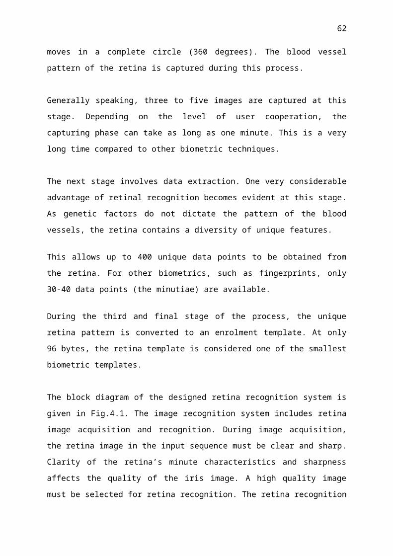
62
APPENDIX B
The following images are the databases of the program, which used as input of the program.
h1.bmp h2.bmp
h3.bmp h4.bmp
h5.tif h6.tif
h7.tif h8.tif

63
h9.tif h10.tif
h11.tif h12.tif
h13.tif h14.tif
h15.tif h16.tif
h17.tif h18.tif

64
h19.tif h20.tif
h21.tif h22.tif
h23.tif h24.tif
h25.tif h26.tif
h27.tif h28.tif

65
h29.tif h30.tif
h31.tif h32.tif
h33.tif h34.tif
h35.tif h36.tif
h37.tif h38.tif

66
h39.tif h40.tif
h41.tif h42.tif
h43.tif h44.tif
h45.bmp h46.bmp
h47.bmp h48.bmp

67
Database Fragment
APPENDIX C
Neural Network object:Architecture:
numInputs: 1numLayers: 2biasConnect: [1; 1]inputConnect: [1; 0]layerConnect: [0 0; 1 0]outputConnect: [0 1]numOutputs: 1 (read-only)numInputDelays: 0 (read-only)numLayerDelays: 0 (read-only)subobject structures:inputs: {1x1 cell} of inputslayers: {2x1 cell} of layersoutputs: {1x2 cell} containing 1 outputbiases: {2x1 cell} containing 2 biasesinputWeights: {2x1 cell} containing 1 input weightlayerWeights: {2x2 cell} containing 1 layer weightfunctions:adaptFcn: 'trains'divideFcn: (none)gradientFcn: 'calcgrad'initFcn: 'initlay'performFcn: 'mse'plotFcns: {'plotperform','plottrainstate','plotregression'}trainFcn: 'traingdx'parameters:adaptParam: .passesdivideParam: (none)gradientParam: (none)

68
initParam: (none)performParam: (none)trainParam: .show, .showWindow, .showCommandLine, .epochs, .time, .goal, .max_fail, .lr, .lr_inc, .lr_dec, .max_perf_inc, .mc, .min_gradweight and bias values: IW: {2x1 cell} containing 1 input weight matrix LW: {2x2 cell} containing 1 layer weight matrixb: {2x1 cell} containing 2 bias vectorsother:name: ''userdata: (user information)
- Matlab output of retina recognition system -