the aerodynamic design of wings with cambered span having ... · technical report r-152 the...
TRANSCRIPT

NASA TR R-152 - ..ZC_
I -4 L
m m - 0 -= -----I- NATIONAL AERONAUTICS AND
SPACE ADMINISTRATION LC)A~\ c;i)p E AFW W m * E P 1
KIRTLANi =$ = MS;
TECHNICAL REPORT R-152
THE AERODYNAMIC DESIGN OF WINGS WITH CAMBERED SPAN HAVING MINIMUM INDUCED DRAG
BY CLARENCE D. CONE, JR.
1963
~
For -le by the Superintendent of Documents. US. Government Printing OIBce. Wasbingbn. D.C. 20402. Single copy price, 35 cents
https://ntrs.nasa.gov/search.jsp?R=19640006060 2018-05-28T18:57:41+00:00Z

TECH LIBRARY KAFB, NM
00b8223
TECHNICAL REPORT R-152
THE AERODYNAMIC DESIGN OF WINGS WITH CAMBERED SPAN HAVING MINIMUM INDUCED DRAG
By CLARENCE D. CONE, JR.
Langley Research Center Langley Station, Hampton, Va.
I


CONTENTS SU~MMARY -________._...-.--..--.----------------------------------------
INTRODUCTION __.._.._..__..___..~___.__._.._....~....~~-_--~~--~-------
S Y M B O L S _ _ _ . _ _ _ _ _ . _ _ _ - - - - - - . - - - - - - - - - - . - - - . - - . - - - . - - - - - - - - - - - - - - - . - - . - - -
T H E ])RAG POLAR OF CAMBERED-SPAN WINGS-_ - - . . .______________. _ _ PROPERTIES O F CAMBERED WINGS HAVING MINIMUM INDUCED
D R A G _ . _ . . _ . _ _ _ . ~ . _ . _ _ _ ~ _ . _ . _ _ _ . . _ . _ _ _ _ . . _ _ . _ _ . - ~ ~ _ - ~ - - - _ - - - ~ ~ - - - - - - - - - The Optimum Circulation IXstribution.. - -. - - -. - - - - - - - - - - - - - - - -. - - - - - - -. - - The Effective Aspect Ratio ______________._._._____________________------
T H E DESIGN O F CAMBERED WINGS _ _ _ _ _ _ _ _ _ _ _ _ _ _ _ _ _ _ _ _ _ _ _ _ _ _ _ _ _ _ _ _ _ _ _ _ I>et,erinination of the Wing Shape for Maximum LID- - -. - - _ - _ _ _ - _ _ _ - _ _ _ - - _ _
Specification of design requirements- - - - - - - - - - - - - - - -. -. - - - - - - - - - - - - - - - - 1)eterniination of minimum value of chord function- - - -. - - - - - - - - - - - - - - Determination of wing profile-drag coefficient and optimum chord function- - The optimum cruise altitude- -. - - _ _ - - - - - - - -. -. - - - - - - - - - - - The effective downwash distribution at cruise- - . . -. -. -. - - - - - -. - - - - Wing twist function for minimum induced drag._. - -. -. -. -. -. -. -. - - - Final wing form__ _ _ _ _ _ _ _ _ _ _ . . ~ __. ~ _....__.. .._.._.._. ..____.___-.__
.4ddit.ional I>rsign Considerations. . . ~. . . ~ . . . . . ~ . . . . . -. . . . . . . . . . -. -. . . . . - -.
Section profile srlection _.__. . . . . . ~ ~. ~ ~. . . . ~. . . . . . . . . -. . . . . ~. . .. . - _ _ _ Angle-of-attack variations. ~ . . . . . . . -. . . . . . . . -. . . ~. . -. . . . -. -. ~. . . . - - Take-off and landing rcquircincnts.. - -. . . ~ . . -. . ~ . . . . . . . . . . . . -. . . . . . _ _ Structural considerations- - - . . -. . - -. -. . - - - - - - - -. -. . - - -. . -. - -. . -. - - - - Special missions- - __________. -. . _ _ -. _ _ _ _ - _ _ _ _ _ _ -. __. _ _ - - _ _ _ _ _ _ -
II,LUSTRATIVE TIESIGN OF A CAMBER.El>-SPAN WING-. - -. _ _ -. -. . - - - - _ _ Basic Design Conditions ___________..____.____________________ _. .-.... - - -
The Spanwise Camber-Line Geometry. _ _ _ ___. - __. - -. . -. - -. -. . . . -. . . -. - . . -. The Chord Function c(s) _________. .._...._.___. .. . ~ - . ._.__.....__._-.. ~- The iVing Ilrag Polar for Minimum I i i t l u w d l h g . . . ~ ~ ~ . . . . . . . ~. . . ~ - The Optimum Crnisc Altitude ..__. . . . . . ~ . ~ . . . ~ . . . ~ . . . ~ . . .
The Efrct.ivr 1)owiiw:tsh a t Cruise,.. . . . ~ ~ . . ~ . ~. . . . - . . ~
The Twist Fuiirlion e(s). .. . . . ~. . . ...
The Final Witig Form.._. . ~ . . ~. ~ . . . . . . . . ~ . ~-
I)I~;TERMINAT1ON O F T H E WING I’ITCIIING MOMENT.. .. .
Pit.ching Moment of the Most Gencral Wing Form .___.. . ~. . . . . . ~ . . - Thc section pitching-moment contribution.. . . . . . . . - . . . . . . Wing pitching moment about Y-axis.. . . . . . . . . . . ~ ~ .-. . . ~. . ~. . .~ . . .
Wing moment about arbitrary axis._. . . . . . . ~ . ~ -. -. . -. . . . . ~. . . ~ ~. . . . . _ _
Wing pitching moment about Y-axis-. .__.____. . . . . . . . . . . . . . ._._. . . . . .
Pitching moment about an arbitrary axis. - _ _ _ _ . -. . . . . . . . .. ~ .. . ~ - .-. . . . ~. . . . . . -. .. . ._. . _-. - ~ -
. . . .. . . . . - .__. . . _ - - - ~. -
-. ___. ._. ~. ~. ._. . _. ._. ._. . . . - . -. . . . . . .___._________
CONC1,UI)ING REMARKS.. . -.- ~. ._ .. . .__.._.._. ._.._..__________________
Al’1’I~;NI)TX A-TIIE ItIC1,ATIONSIIIP OF L I F T TO INDUCED DRAG FOR - - - - - - - - - - - - - -
Pitching Moment of a IVing Constructed of Similar Profiles.. ~. . .._ .. .__
Variation of C,”,J With CL for General Wing Form.. .
Variation of C,, With C L for Sirnilar-Profile Wing_- . Locus of Trim Axis-
OPT1 M AL1,Y J,O A I > E I > AIRFOI1,S. - - - - - - - - - - - - -. . -. . .
I ~ E F E R E N C E S I1 I
Page 1
1
2
3
4 4 5
6 7 8 8 9
11 11 12 12 12 12 13 13 14 14
14 15 15 17 17 18 78 18 19
21 22 22 23 23 23 23 24 24 24 24
25
26
26

TECHNICAL REPORT R-152
THE AERODYNAMIC DESIGN OF WINGS WITH CAMBERED SPAN HAVING MINIMUM INDUCED DRAG
By CLARENCE D. CONE, JR.
SUMMARY
The basic aerodynamic relations needed f o r the design of wings with cambered span having a mini- mtcm induced drag at spect$ed Jlight conditions are developed f o r wings of arbitrary spanwise camber. Procedures are also developed for determining the physical wing .form ~equired to obtain the maximum value of lift-drag ratio at cruise, when the wing spanwise camber-line and section projiiles are speci-
Jied, by optimizing the wing chord and twist clistri- butions with respect to both projile and inrlitcerl drags.
The application of the design procedure is illus- trated by determining the physical wing form for a circitlar-arc spanwise camber line. The e$iciency of this cambered wing i s compared with that of a n ey"!-span, frat wing of elliptical planform which satisjiee the same set of fright operating conditions ass does thr cambered wing.
The wing pitching- m o me nt e p a t i o n s f o r opti- ma I1 y loa rlr (1 cain br r f d-spa n wings at d p s ign flight contlitions are nlso developetl f o r use i n trim annlyses o n complete aircraft designs.
INTRODUCTION
Tlle theoreticnl considerations of refererice 1 indiciited that the reduction in induced drag attaiimble with optiinally loaded, nonpliinar lifting systems might allow some g:iin in wing aerody- naniic efficiency (lift-drag ratio) over that of flat wings when the lateral spiiri of tlie wing system is limited by operational requirements. Tn purticu- Iar, i t wtis shown that substantial increases in effective tLspect ratio (as compared with that of flat wings of equal projected span) could be obtained with relatively simple wing forms having cumbered spws, that is, wings in which the span
has curvature in a plane perpendicular to the direction of flight. Reference 1 pointed out, however, that the practical realization of a net efficiency increase would depend in considerable measure upon the ability to construct cambered wings with profile-drag coefficients and structural weights which would not greatly exceed those of the equivalent flat-span wing producing the saine lift. Otherwise, the benefits of the increased effective aspect ratio attainable with c:iniber might be cancelled by increased profile drag, ant1 un increrised operittioniil lift force.
The tiforeriientioned efl'ective-aspect-rNtio prop- erties of cambered-span airfoils were derived by a theoretical treatment of the ideal vortex systems necessary for ininimuin induced drag, without consideration of the physical wing forms needed to obtain the optinium distributions of vorticity. Tn order t o investigate the overall performance gains obt:iinal)le with such airKoiIs, the details of t tie physical wing design niust be considered. These tlet:iils include not only tierotlyniitnic factors but iilso the cffects o l the wing structural weight on tlie opercitioniil efficiency (ref. 1). I n g~nernl , however, structurttl \veiglit effects can he t alien into iiccount after the acrotlynannic design of the wing is specified. The purpose of this nnaIysis, consequently, is to develop the general relntions needed for the aerodyniiniic design and efficiency evn1u:it ion of airfoils which have arbitrarily speci- fied camber fornis (such its circular-arc spanwise segments and semiellipse curves) and which possess ininimum induced drag a t specified flight condi- tions, without regard to structural weight effects. The methods by which the optimuni lift loading, corresponding to the rniniinuin induced drag of a given spanwise citinber line, can be cleterniined
1

2 TECHNICAL REPORT R-15 8-XATIONAL AERONAUTICS A N D SPACE ADMINISTRATION
are presented in reference 1. The relations are developed in a form which permits a direct efficiency comparison to be made between an elliptically loaded flat span wing and an optimally loaded (minimum induced drag) wing of arbitrary camber having an equal projected span and pro- ducing the same lift force. Thus, in addition to prescribing the wing shape necessary for mininiurn induced drag with a given. camber form under specified flight conditions, the results also show the relative efficiency of the complete cambered wing. The results may be used to investigate the maximuin values of lift-drag ratio attainable with any given camber forni for any prescribed set of flight operating conditions.
Although the intention of this paper is to discuss only the general design procedure for wings with arbitrary camber, without consideration of the comparative efficiencies of any specific camber shapes, actual calculations are presented for a wing having a circular-arc camber line, in order to illustrate the design procedures and to indicate the order of magnitude of the lift-drag ratio attainiible for R particular set of operating conditions.
Consideration is given herein only to the design of the basic cambered wing. I n the design of a coniplete aircraft, the entire vehicle configunttion must ol course be considered and the parasite drag of the fuselage and other components intro- duced into the design calculations. However, the procedures outlined herein specifically for wing design are easily adapted to a complete aircraft design by proper inclusion of rill the coiiiporient drag coefficients. In addition, the relations dis- cussed t~pply equally well in principle to the design of more complex wing forms such as those having compound camber, or bninched tips (ref. l ) , as well as to the design of low-drag hydrofoils. Because of the restricted allowable span length of most hydrofoil systems, the use of cambered-span hydrofoils appears advitntageous as a means for reducing both the induced drag and support-strut drag of conventional systems. The curvature of such hydrofoils might, also allow some reduction in free-surface effects. The theoretical basis and practical application aspects of cambered-span wings are discussed in reference 1.
When the use of cambered-span wings is con- sidered for specific aircraft designs, a knowledge
of the pitching-moment characteristics of such wings is of considerable importance. The curva- ture of the span results in a vertical distribution of the drag forces and this distribution in turn affects the wing pitching moment. A quantita- tive knowledge of this effect is necessa.ry if the aircraft is to be designed to possess desirable longitudinal trim characteristics. Consequently, the subsequent section “Determination of the Wing Pitching Moment” presents the develop- ment of the various aerodynamic relations needed for determining the pitching moment of optimally loaded cambered-span wings for any arbitrary pitch-axis location. These relations are essen- tially confined to the calculation of the pitching moment of the optimum wing form a t specified cruise conditions.
SYMBOLS
aspect ratio
const ant , f1 - 5 I y . - l ro wing span of flat reference wing projected wing span of cmil)ered-
wing total-drag coefficient wing induced-drag coefficient wing profile-drag coefficient section drag coefficient wing lift coeficient wing lift coefficient for (L/D)mor section aerodynamic-force (lift) co-
efficient section aerodynariiic-force coeffi-
cient for wing (L/D)mnl. wing pitching-monieii t coefficieii t
about arbitrary axis through point P
wing chord mean aerodynan~ic chord of flat
wing root chord wing total drag force wing total drag force intensity
wing induced drag force intensity,
spcmwise-camber depth (fig. 3 ) :ierodynaiiiic-force loading intensity
span wing
wing
(force per unit length)
Pwr
(fig. 7)
THE AERODYNAMIC DESIGN O F W I N G S WITH CAMBERED SPAN HAVING MINIMUM INDUCED DRAG 3
G
h k L L'
M M'
m
NA
P
S S'
7'
S
S t V W W
700
X
XP
Y, 2
Y' 2'
Zp
ZT
CY'
CY'*
CY
f f i
a 0
P
constant, J1 L s e c rc~y -l ro
flight altitude induced drag efficiency factor wing lift force lift-force intensity (force per unit
wing pitching moment section pitching moment
S constant, ~ - b c0B - 2
length)
dynamic pressure radius of curvature ol circultir :ire
wing area of flat reference wing wing tirca of cambered-span wing,
tirc-sp:in coortliiinte (fig. 2) arc-tip coordinate flight velocity weight force effective downwasli velocity downwasli velocity a t center of
('artesian coordinate in free-stream
longit udirial coordinate of iirbit r:iry
('iirtesiiin coordinates ol sprinwise
diininiy variable of integriition distance of line-of-action ol Do'
z-coordinate of arbitrtiry asis coordinate of trim axis geometrical angle-of-attack fuiict ion effective angle of attack effective angle of attack for
induced angle-of-attack function geometrical angle of attack of wing
span
tlirec t ion
asis
ccmiber line z(y)
above Y-:txis
( U D ) m a . Z
root section d camber fwtor, __
b'/2
r wing circulation distribution ro circulntion of wing root section
nondirnensional coordinate, -L b'/2
noncliniensional coordinnte, - b'/2
Y
6 z
e wing twist function P atmosplieric density
P8 1
cr atmospheric density ratio, p / p s l
atmospheric density a t sea level
1 d z slope of camber-line tangent, tan- - 7 span ratio, blb' dY 9
Subscripts:
c condition a t cruise 4 4 .f flat-span wing L condition a t landing ?nux niiixinium 0 in plme of syiiiiiietry P arbitrary nxis location 7' IF inoiiient about 17-:ixis
) are used tliroughout to denote the independent vnrirtble of the function preced- ing the parentheses rind should not be interpreted
r to nietiri iiiultipliccitiori. Exciniple : -(s) denotes
1'0
about quarter-chord point of section
t riiii-axis 1oca t ion
Parentheses (
1 that - is t t function of s . ro THE DRAG POLAR OF CAMBERED-SPAN WINGS
In reference 1 tlie relation between the lift coefficient and the induced drag coefficient for :in?- cainbered-span wing is expressed :is
where the lift coefficient PL and aspect ratio A are based on the span length and wing area of a flat, elliptical-planforrn wing arbitrarily chosen as a basis for deterniining the induced drag of the cambered wing. The factor k is an efficiency f ac tor which de term ines the m axini uin effective aspect ratio kA of the curved wing and is shown to depend only upon the geometrical form and
4 TECHNICAL REPORT R-15 2-XATIONAL AERONAUTICS A N D SPACE ADMINISTRATION
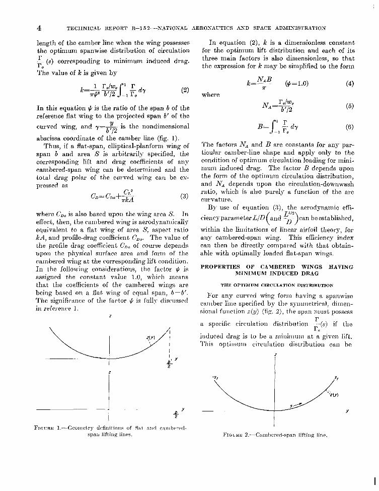
length of the camber line when the wing possesses the optimum spanwise distribution of circulation - (s) corresponding to minimum induced drag.
The value of k is given by
r ro
In this equation + is the ratio of the span b of the reference flat wing to the projected span b' of the
is the nondimensional b 12
abscissa coordinate of the camber line (fig. 1). Thus, if a flat-span, elliptical-planform wing of
span b and area S is arbitrarily specified, the corresponding lift and drag coefficients of any cambered-span wing can be determined and the total drag polar of the curved wing can be ex- pressed as
curved wing, and Y = ~ Y
( 3 )
where CDo is also based upon the wing area S. In effect, then, the cambered wing is aerodynamically equivalent to a flat wing of area S, aspect ratio kA, and profile-drag coefficient CDo. The value of the profile drag coefficient CDo of course depends upon the physical surface area and forin of the cambered wing a t the corresponding lift condition. I n the following considerations, the factor $ is assigned the constant value 1.0, which means that the coefficients of the cambered wings are being based on a flat wing of equal span, b=b'. The significance of the factor $ is fully discussed in reference 1.
I n equation ( 2 ) , k is a dimensionless constant for the optimum lift distribution and each of its three main factors is also dimensionless, so that the expression for k may be simplified to the form
where
~~
1
1 FIGURE l.-Geoiiietry defiiiitioiis of flat a i i d cari~hc~rc~d-
span lifting lilies.
(4)
(5)
The factors NA and B are constants for any par- ticular camber-line shape and apply only to the condition of optimum circulation loading for mini- niuni induced drag. The factor B depends upon the form of the optimum circulation distribution, and NA depends upon the circulation-downwash ratio, which is also purely a function of the arc curvature.
By use of equation ( 3 ) , the aerodynamic effi-
ciencyparaineter LID and - ~- can be established,
within the limitations of linear airfoil theory, for any cambered-span wing. This efficiency index can then be directly compared with that obtain- able with optimally loaded flat-span wings.
PROPERTIES OF CAMBERED WINGS HAVING MINIMUM INDUCED DRAG
( Y)
THE OPTIMUM CIRCULATION DISTRIBUTION
For any curved wing forin having a spanwise camber line specified by the symiiietrical, dirnen- sional function ~ ( y ) (fig. 2 ) , the span must possess
a specific circulation distribution -(s) if the
induced drag is to be u niiniiiiuni a t a given lift. This optiriiuni circulation distribution can be
r ro
FIGURE 2.-Cambered-span liftiiig line.
I

THE AERODYNAMIC DESIGN O F W I N G S WITH CAMBERED SPAN HAVING MINIMUM INDUCED DRAG 5
I .65 B
determined by either the conformal-transforma- tion or the electrical-analog technique discussed in reference 1. These methods can also be used to determine the value of NA (eq. (ti)), and inte- gration of the nondimensional circulation loading T / r , determines the value of B (eq. (6)). For families of camber lines such as circular-arc seg- ments or semiellipses, the optimum distribution r/r,, and the constants NA and B can be expressed as functions of the camber factor p which describes the particular arc members. (See fig. 3.) The
/
I-
/- /’- I .o
.E
- r .6 ro
.4
.2
0
FIGURE 3.-Definition of camber factor 0.
.I .2
optimum nondimensional circulation loadings and corresponding values of NA and B are presented in figures 4 and 5 as functions of p for circular and semielliptic arcs, respectively, in order to illustrate the loading variation with camber for simple arc forms. The distribution r/ro for the case p=O in each figure corresponds to the loading for a flat wing, and it is evident that the effect of camber is to increase the relative loading of the outer portion of the projected span.
THE EFFECTIVE ASPECT RATIO
When the values of NA and B have been deter- mined for a given camber line z(y), the value of the efficiency factor k can be calculated by equa- tion (2), for # = l . O . Since the effective aspect ratio of a cambered-span wing is then equal to k A , where A is the aspect ratio of the reference elliptical wing of equal span, the induced drag of the curved wing will be less than that of the flat wing for equal lifts when k > l . This result, of course, is dependent on the assumption that the curved span is optimally loaded a t all values of the lift coefficient. The variation of the span efficiency factor k with degree of camber p is
. 3 .4 .5 Y
. G 7 .0 .9 1.0
FIGURE 4. -Variation of the optimum nondiincnsional circulation distribution and c.fficicbncy constants of circular-arc camber lines with degree of camber.
656-793 G-l -2

6 TECHNICAL REPORT R-15 2-XATIONAL AERONAUTICS AND SPACE ADMINISTRATION
NA
.2 . 3 .4 .5 Y
e I 1*65Fwm .550 .2 .4 .6 .8 1.0
P
FIGURE 5.-Variation of the optimum nondiniensional circulation distribution and efficiency constants of semiellipse camber lines with camber factor B.
presented in figure 6 for the complete fniiiilies (0 5 p 1) of circular-arc segiiients and semi- ellipses for the condition += 1 .O.
The following considerations of cainbered-span wings are divided into three parts. The first part presents a developnient of the relations necessary for designing wings which will possess a niaxiniuin value of LID (for the imposed structural restraints) for specified flight conditions. The second part, presents actual cwlculwtions for a wing with circular-arc cainber RS :in illustration of the design procedure, and as an indication of the magnitude of the efficiency obtainable with cam- bered wings. The third part presents relations for determining the wing pitching monients a t design flight conditions.
THE DESIGN OF CAMBERED WINGS
Consider first a flat reference wing of elliptical planforin which is specified by stating its span b, wing area S, and constituent section profiles. The aspect ratio is tlien also deterliiined, A=b2/S. The force coefficients :ire given by
(7) I; PL=-
1 ,j pv2s
These equations in turn can be used to determine the wing efficiency parameter LID as a function of CL .
Consider now an optiiiially loaded, ctiiiibered- span wing of projected span length b' equal to that of the flat wing and producing mi equal lift zit the
same dyiiwiiiic pressure - p P . This caiiibered
wing can have any desired coiiibimition of wing twist, chord distribution, and section profile varia- tion, subject only to the requireinent that a t the prescribed flight conditions under coilsideration the wing possesses the optiiiiurii circulation load- ing r ( S ) for which the iiiaxiiiiuiii efficiency factor k applies. If the wing aren S of the reference flat wing is used as the basis for determining the force coefficients of this cambered-span wing, there results
(9)
1 2
I,
CL2 c,= C,,S-- n-kA

THE AERODYNAMIC DESIGN O F WINGS WITH CAMBERED SPAN HAVING M I N I M U M INDUCED DRAG 7 1.5
I .4
1.3
k
1.2
I. I
I .c
5
/ - /
_ /
/
.-
/
I
/
I
/
I
/
I
/
/
/
/ '
/
/
/
/
I
/ C
I
/ ular-
I
/ '
----
/ /
B FIGURE G . -V;iri:ttioii of t.he eWcicsiicy factor k of circular and st:~riic~llipse arcs Lvith the cattiI)or factor p.
These coefficients now determine the lift-drag ratio LID for the citinbered wing.
A coniparison of equations (8) and (10) indicates that the cambered-span wing can attain a higher total aerodyntuiiic efficiency than tlie flat wing a t equal lift d u e s if k> 1 .O, provided of course that cyD, is not proportionrttely larger than C D , ,. Because tlepcnds criticdly upon the wing section profiles :ind pliysicd wing surface area, tlie ability to reiilize the full induced-drag efficiency gains offered by sptinwisc c:iiiiber obviously rests upon the possibility of constructing curved wings with relatively small surftice areas or low drag profiles or both. As is discussed subsequently, a considerable latitude exists for designing wings that possess low values of CDo a t specified flight conditions, since the value of k depends only upon the at tttiniiient of the optiiiiuiii circulation loading r(s) and is independent of the pliysical iiieans for obtaining this distribution.
It should be noted that the use in this analysis of a given flat wing :is the basis for deterniining the coefficients of the cambered wing is purely arbitrary and is valuable priiiiarily for efficiency comparison purposes. I n reality, any area S could be used to define the force coefficients of the
cambered wing. 'I'lie induced drag of a flat, elliptically loaded wing is of course independent of the physical wing area and hence of the physical aspect ratio for a given span and lift, as can be seen from the fundamental relation
'I'liis fact is discussed in sollie detail in reference 2, pages 32 and 33, :ind in :tppenclis A of this report.
DETERMINATION OF THE WING SHAPE FOR MAXIMUM LID
The first step in the design procedure is the specification of the nondi~iiensional camber func-
2 tion 6(y) where 6= - and y= y-. b'I2 b'l2 This func-
tion then becomes the corresponding tlitiiensional camber line z(y) when the projected span length b' is given. Obviously, the particular value of b' to be used for a given design depends entirely upon criteria associated with the requirements of the specific aircraft mission, and hence no general procedure can be stated for determining its selec- tion. Once the camber line 6(y) or z(y) is specified,
the values of I C , NA, and B, and the function -(s) r . ro

8 TECHNICAL REPORT R-15 2-XATIONAL AERONAUTICS A N D SPACE ADMINISTRATION
corresponding to minimum induced drag can be determined.
The next step is the selection of the area S of the flat reference wing of span b ( = b ‘ ) to be used as a basis for the coeacients. The choice of equal span lengths as a basis for comparison rests upon the fundamental importance of the span in determin- ing the induced drag. (See eq. (Al) and ref. 1.) While the value of the area S is purely arbitrary, it is convenient to use the value of S corresponding to that of the “optimum” flat wing which best satisfies the requirements of the specific mission for which the curved wing is being designed. Then the aerodynamic efficiency of the resulting curved wing can be directly compared with that of the optimurri flat wing.
Specification of design requirements.-In order to design the wing for practical flight operations, certain basic design requirements must be speci- fied. These requirements will determine, to some extent, the design procedure. For the purposes of this analysis, however, the design requirements are taken as the speed VL corresponding to the desired landing speed, the load WL corresponding to the total weight supported by the wing a t landing, the design cruise speed Vc, and the initial cruise weight W,. These criteria are of course arbitrary but serve as a basis for development of the general design relations. Since the landing speed in gen- eral is low compared with the cruise speed (depend- ing upon the particular aircraft mission), the land- ing speed then determines the minimum physical area of a cambered-span wing. Under certain conditions, take-off speed and weight rather than landing speed and weight may be the governing factors.
Determination of minimum value of chord function.-A cambered-span wing is usually designed to possess its niaxiniuni value of LID a t sonie specific cruise flight condition, and the physi- cal form of the wing is therefore such that the optiniuin circulation distribution for minimum induced drag is obtained. That is, the wing is designed priniarily for optiiliurn efficiency a t cruise. It is assuiiied for this analysis, however, that by a proper use of wing flaps or other variable chord- wise ctiiiiber devices, the optiniuiii nondiniensiorial
circultition distribution -(s) can also be obtained
(approsiniately) at landing conditioiis. Then the
r ro
ditions. Thus the optimum distribution r/r, can be used in conjunction with the landing require- ments to determine the minimum allowable chord distribution of the wing.
I n terms of the nondimensional coordinate r=y/(b’/2), the lift force at any f ight condition
becomes, when equation (6) is used,
(13) b‘ L=pvro B
for the design flight and landing conditions. landing, L= WL and V= VL, so that
For
Here ro,L is the circulation in the plane of sym-
metry of the wing a t landing. Since -(s) can be
established by the methods of reference 1, the dimensional circulation distribution r(s) along the arc span can be determined as
r r o
The aerodynamic-force loading intensity F‘ along the camber line (fig. 7) is given by
~ ’ ( s ) = ~ v r ( ~ ) (16)
The corresponding section “lift” coefficient varia- tion e l (actually c z determines the aerodynamic-
FIGURE 7.--Acrody11ar1iic-force loading iiiteiisit y and its vaiues of NA and B applyto both basic flight con- relat.ion t o lift intensity.

T H E AERODYNAMIC D E S I G N O F W I N G S WITH CAMBERED S P A N HAVING MINIMUM IN,DUCED DRAG 9
force intensity) is given by
and equations (14), (15), and (17) give the chord distribution for the landing condition as
This equation, upon specification of the function c ~ , ~ , determines the necessary chord distribution and minimum allowable physical surface area of the wing as set by the landing requirements. Obviously, the minimum allowable value of the “effective” wing area S‘ is determined by the maximum allowable value of c ~ , ~ , where
It also follows from equation (18) t,hat if each section profile is operated a t the same value of c ~ , ~ , the chord distribution c(s) is uniquely deter- mined by the camber-line geometry z(y) since r
- (s) is a function only of the arc shape. r o
Although equation (18) determines the mini- mum value of the allowable chord length which still satisfies the landing requirements, this distri- bution is not necessarily the optimum one corre- sponding to the rnaximum value of LID for the wing at a given lift coefficient CL, since the profile drag is critically dependent upon the actual section chord length. Thus, if the wing is to operate a t the nisxirnuni possible value of LID a t a given lift coefficient, the chord distribution must be optimized so as to have minimum profile drag. This optimization procedure is considered next. If the optimum chord distribution is less than that required for landing, the limiting distribution as given by equation (18) must of course be used.
The general form of equation (18) for any flight condition for which the induced drag is to be minimum and in which W, p , and V are specified is
Determination of wing profile-drag coefficient and optimum chord function.-When a wing section profile is selected, the section drag polar cd(cI) and the section aerodynamic-force curve cl(a’) are specified. The wing profile-drag coeffi- cient is then given b y
where cd is the section drag coefficient correspond- ing to the operating value of c; of the section. The drag coefficient as given by equation (21) does not, of course, include any of the effects such as tip-drag and profile-drag changes which may occur with the curved, three-dimensional wing. If it is anticipated that such effects wil l be significant, an additive term can be applied in equation (21) to account for them. Assume now that the wing is constructed entirely of similar profiles all of which are operating at the same value of e l ; the total wing profile-drag coefficient is then
S‘ x The total wing-drag coefficient then becomes
In this equation the profile-drag term appears as a function of el, where c E is the section “lift” coefficient corresponding to any given flight condi- tion. Since, however, tbe wing is being designed for inrtxinium LID at cruise, cd must now be expressed as a function of C, (the total lift coeffi-
cient) so that the function (C,) can be deter-
mined. The relation between c z and CL is established
by substituting the general weight expression
D
1 2 w=cl, - pV2S
into equation (20), and after rearrnngernent the desired relation is obtained as
S r

10 TECHNICAL REPORT R-15 2-NATIONAL AERONAUTICS A N D SPACE ADMINISTRATION
Since the factor in brackets is a constant, the relation between the section and total wing-lift coefficients can be expressed simply ns
c,=mCL where
s r m=- - b' Po GB - 2
S (27)
The individual factors r/r, and c are of course functions of the arc-span coorcliniite s but their ratio is a constant when each wing section is operated at the same value of c l . (See eq. (20).) The total wing-drag coefficient can be expressed as
In order to determine the chord distribution that will make CD a minimum for w, given value of C,, it is necessary to find the optimuni value of the root chord ea. The optimum chord-length distribution a t that C, will then be given by
(29) r r0
c ( s ) = c , ( s )
I n order to find this optiniuni value of ea, the wing profile-drag coefficient
(30) S'
cDo=cd(mCL) x must be espressecl as a function of eo. equation (27),
From
S 7123- b' c,B - 2
and substitution of c(s) from equation (29) yields
s=yt c(s)ds
ra Since the second integral is a constant for any particular camber line when it is optimally loaded,
equation (32) can be written as
b' X ' = T Gc, where
(33)
(34)
Substituting these values into equation (28) yields as the drag polar
I b'
where it should be noted that the fact,or in paren- theses is the value of e l for which cd is to be evel- uated; it is a functional relation and not R niulti- plication factor. The equation for LID as a function of eo, for a constant value of C,, is given by
Now if the section drag polar of the selected profile is used, a plot can be made a t constant C, of the variation of LID with c,, and the value of c, for which LID becomes a niaxiinuni determines the optimum chord distribution for that operational value of C,. When this procedure is carried out for n range of C, values, a plot of L/D against C, will deterniine the optimum cruise lift coefficient C,* corresponding to the absolute niasimum value of wing LID, denoted by and the cor- responding value of ea. Then, from equation (30) the profile-drag coefficient a t cruise is given by
(37) CD,=cd(m CL*) S' -
S
where S' of course depends upon the correspond- ing optimum value of c,.
Since the foregoing procedure deterniines the optimum chord distribution not only for the opti- muni cruise condition (C,* and but for the entire lift-coefficient range as well, the wing dimensions for niaximuni LID a t any other value of CL are also specified.

THE AERODYNAMIC DESIGN OF W I N G S WITH CAMBERED SPAN HAVING M I N I M U M INDUCED DRAG 11
It should perhaps be emphasized that the rela- tion between LID and CL as given by equation (36) for the optimum value of e , at each C, is not the variation of a particular wing LID as the angle of attack is increased. It merely gives the relation between LID and CL for the optimum wing form a t a given CL value, and for each value of CL the wing form will be different (different chord distribution).
The optimum cruise altitude.-If cruise a t the most efficient lift coefficient CL is to be txttained, the wing inust fly a t the altitude where the opti- mum equilibrium condition
1 w, = cL*zucps tvc2s
is satisfied, since the cruise speed V, is specified. (Alternately, of course, the cruise altitude could be specified and the cruise speed calculated. If both the altitude and speed a t cruise are specified, the necessary CL for cruise is determined and the foregoing procedure gives the maximum value of LID at this C> value.) The subscript C denotes the cruise values of the variables and cC is the density ratio pc/psl . The density ratio is of course a function of altitude h and uC=u(hC). The opti- mum cruise altitude is then given implicitly by
(39)
tlirough the altitude-density function ~ ( h . ) . air density a t cruise altitude is
The
Pc = UcPs 1 (40)
In equation (39), Wc is the initial cruise weight supported by the wing. In practical aircraft op- eration with conventionally fueled engines, J4’c will decrease as fuel is used up and if the aircraft is to fly a t CL* continuously, the altitude must increase in such degree that
wc= Constan t UC
The effective downwash distribution at cruise,- The effective downwash distribution along the cambered span a t cruise must now be determined so that the geometrical twist necessary for opti- mum loading of the wing can be calculated. The
effective downwash velocity w(s) is shown in reference 1 to be given by
w(s) =wo cos r(s) (42)
In this equation w o is the niaximuin downwash (occurring a t the center of the span) and r is the slope of the camber-line tangent a t point s. The effective downwash at a point s of the camber line is the component of the total induced velocity a t point s normal to the camber line (fig. 8 ) . In the case of symmetrical arc forms the total induced velocity is w, and is constant along the arc.
From equation (5)
(43)
and if equations (13), (42), and (43) are used with the condition W=L, i t follows that
2-- cos 7 (s) (44) W w(s) =
P V [;I BN.4
Then from the expression for the camber line, z(y), there follows
dz tan r=- d?i
whence 1 cos r= - -~ dl+W
(45)
This equation defines the relation cos r as a. function of the coordinate y, and since
(47)
* WO
FIGURE S.--T>iagram of induced velocity and its relation to effective downwash.

12 TECHNICAL REPORT R-15 2-ITATIONAL AERONAUTICS AND SPACE ADMINISTRATION
cos is also determined as a function of s (the arc-span coordinate). Thus, the effective down- wash distribution corresponding to minimum in- duced drag becomes known for any flight condi- tion. For the cruise condition, use of equation (44) yields
cos r(s) (48) wc w(s)= pCvc [ ~ - J B N ~
Wing twist function for minimum induced drag.-The induced angle-of-attack (~~(8) is defined by
where w(s) is the effective downwash
distribution
(49)
distribution . . along the arc span. At cruise conditions, sub- stitution of equations (39) and (40) into equation (48) gives
The induced angle of attack a t cruise is, therefore,
f
This equat,ion can alternately be written as
by using the usual linearizing assumptions and equation (4).
The required geometrical angle-of-attack dis- tribution a(s) a t cruise is given by
a(s) =a&) Sa’ * (53)
where a’* is the section angle of attack correspond- ing to the optimum section lift coefficient cl= mC’. Under the foregoing assumption of geo- metrically similar profiles for all sections, a’* is of course constant. Substitution of equation ( 5 2 ) into equation ( 5 3 ) gives the geometrical angle of attack (measured as the angle, in the plane I J O I T ~ ~ ~
to the camber line, between the direction of V
and the section chord line) a t cruise in terms of the camber and design lift coefficient CL*
CL* a(s)=(Y’*+2 - cos r(s) ?rkA (54)
If the geometrical twist function O(s) is defined as
e(s) = ff (8) - (55)
where a0 is the geometrical angle of attack of the root wing section (at s=y=O), it can be seen that the twist for an optimum cambered-span wing constructed of similar profiles will be negative, since (Y decreases as increases, as indicated by equation (54). This relationship means that the wing must possess geometrical “washout” for minimum induced drag a t cruise.
Final wing form.-With the determination of the twist function, all the information necessary for the aerodynamic specification of the total wing form for maximum cruise efficiency is available. The camber line z(y) specifies the frame upon which the chosen section profiles are to be arranged. For simplicity, the camber line can be assumed to pass through the quarter-chord point of each section or else the location of the profiles relative to the camber line can be specified. The optimum chord distribution c(s) , as determined by equation (29) when the optimum root chord length is specified, follows directly from the optimization procedure for maximum LID. Finally, equation (55) for the twist function specifies the angular arrangement of the section profiles along the camber line, and a. gives the geometrical angle of attack of the center wing section.
ADDlTIONAL DESIGN CONSIDERATIONS
Although the design relations presented have included the principal factors involved in optimiz- ing a wing form for specified operating conditions, several other special factors which are of im- portance must be considered in a complete wing design. These are briefly discussed in this section.
Section profile selection.-A small effective wing area S’ is part.icularly desirable for cambered wings, especially when use is made of the thick, laminar-flow profiles, such as characterized by the NACA 65,-618 wing section. Since the section drag coefficient, of such profiles is very small and is essentially independent of the section lift co- efficient over a wide lift range (the drag bucket),

THE AERODYNAMIC DESIGN OF WINGS WITH CAMBERED SPAN HAVING MINTMUM INDUCED DRAG 13
use of such profiles operating at a relativeiy high value of c1 and with a small chord lenqth can result in a substantial lowering of the wing’ profile drag a t cruise as compared with that of more conventional sections, provided that the ful l ex- tent of laminar flow can be realized and that the cruise Reynolds number is not so large that the drag bucket has become very narrow. I n addi- tion, the relatively large thickness ratio of these airfoils provides considerable depth for housing the wing-spar structure. The attainment of a small value for S’, however, depends upon the maximum value of c l that can be attained for satisfaction of landing or take-off requirements. It thus appears highly desirable when such pro- files are used to make ful l use of such high-lift devices as multiple-slotted flaps in order to in- crease to a value sufficiently high for low-speed operation.
I n order to evaluate various wing-section pro- files for optimizing the wing ( L / D ) m u z value a t cruise conditions, the function
+.
4
can be optimized for a series of different profiles, and the profile having the largest value for this parameter can be determined. The final profile selection must of course also be based upon the c ~ , ~ ~ ~ value and upon a sufficient thickness ratio to meet structural requirements.
The optimization considerations itre based upon the restrictions that the wing be constructed entirely of similar profiles all operating at the same value of c l . It is possible, however, to design the cambered-span wing so that it will possess the milximum possible value of LID when the restrictions of operation at constant c 1 and similar profiles are removed. When every sec- tion of the wing is simultaneously operating a t its own value of (L’/D’)maz, the total wing will then have its maximum value of LID for a given lift. For example, if the cruise conditions Wc, Vc, and hc are specified, the value of (L‘/D’)muz can be determined for each section by use of the relation
+
4
(57)
and L’=pcV$c cos 7
-C1QcC cos 7
Under the given cruise conditions, equation (59) leads to the condition
(59) -
c lc= Cons tan t
for any specific section and use of this condition in equation (57) will ultimately determine the optimum chord length, angle of attack a, and twist angle for each section, corresponding to the value of (L’/D‘)maz. The section data used should of course correspond approximately to the anticipated flight Reynolds number of the section.
Angle-of-attack variations.-The optimum cam- bered-span wing is designed primarily for cruise conditions, and the geometrical twist provides the angle-of-attack distribution necessary for the optimum circulation loading a t cruise speed. For lower speeds an increase in section angle of attack is necessary if a constant lift is to be main- tained. Because of the camber of the span, however, an increase in the effective angle of attack of the center wing sections obtained by pitching the wing will have less effect on the out- board section angles of attack, due to the effect of camber, if the wing is rigid. A possible solu- tion to this problem lies in the use of trailing-edge flaps. By a suitable programing of flap deflec- tion, the section lift coefficient can be varied while maintaining a constant section geometrical angle of attack (corresponding to the cruise condition). I n this way, the wing could always operate a t essentially the same flight attitude for take-off, landing, and cruise. I n addition, it would be possible to maintain an approximately optimum circulation distribution a t all flight conditions without need for pitching of the entire wing. The use of such flaps is also quite com- patible with the need for high values of c ~ , ~ ~ ~ and small values of S’ at cruise.
Take-off and landing requirements.-The design procedure outlined above is based upon the speci- fied landing weight and speed. Tnasmuch as the
(60)

14 TECHNICAL REPORT R-15 2-XATIONAL AERONAUTICS AND SPACE ADMINISTRATION
take-off weight is usually considerably greater than the landing weight, for the same the take-off speed must therefore be greater than the landing speed. The take-off speed could be equally well used as the criterion for determining the minimum chord distribution. However, the desirability of maintaining a reasonably small value of S’ for optiniuni LID operation may require some com- promise of the minimum landing or take-off speeds, unless means for obtaining very high section lift coefficients, such as external boundary-layer con- trol, are utilized. For special missions where cruise efficiency is critical, use of jet-assisted talie- off is quite feasible as a means for overcoming any take-off problenis which might exist.
Structural considerations.-The preceding de- sign outline has been based solely upon aero- dynamic considerations without regard to struc- tural factors. The structural factor of priniary importance is the wing structural weight as coni- pared to a flat-span wing producing equal lift. I n a complete design analysis, the effects of struc- t u r d weight niust of course be considered. The effect of the span ratio $ on weight properties, as well as the possibility of utilizing lightweight aeroelnstic wing structures for weight reductions, is discussed in reference 1.
Special missions.-In addition to the possibility of using cambered-span wings for improvement of the efficiency of conventional aircraft, there are a number of special areas where application of such wings may be of significant value. Since the priniary advantage of cambered wings lies in their high effective aspect ratios for a given span length, operational missions where high induced drag is a serious problem are of particular interest. There are several such missions. In the operation of STOL aircraft, the very low take-off and landing speeds require operation a t very high CL values with very high D,. For such airplanes, operating conditions often severely limit the allowable span length and hence the geometrical aspect ratio. In addition to the very high induced drag en- countered by such aircraft, i t is predicted in reference 2 that at very large values of CL (or for sniall values of A ) , the airfoil lift can be appre- ciably reduced by the large downwasli velocities. Use of spanwise camber could help in alleviating both problems. In situations where the physical span length is limited, camber can be used to
increase the effective value of the aspect ratio over that of flat-span wings. Various other areas include efficient subsonic cruise a t extremely high altitudes (where the low density requires high C, values), high endurance aircraft, and cargo aircraft operation with increased payload. Possible sta- bility and control applications are also suggested in reference 1.
ILLUSTRATIVE DESIGN OF A CAMBERED-SPAN WING
I n order to illustrate briefly the application of the foregoing design procedure, calculations have been carried out for a cambered-span wing which satisfies an arbitrary set of prescribed operating conditions. The conditions selected are typical of current operational requirements met by con- ventional-winged transport aircraft. No attempt has been made in this illustration to determine the absolute optiniuni wing forin as regards (L/QmaZ, and the win: chord distribution used corresponds to the niininiuni value as set by the prescribed landing condition. The wing section chosen for the illustration is the NACA 65,-615: profile. However, the use of laminar-flow profiles is in no way mandatary with cambered wings, although such profiles possess some advantages because of their low drag coefficients. It is assumed for purposes of illustration that the section profile-drag coefficients obtained in wind- tunnel tests can be realized in full-scale, practical operation. I n reality, extremely smooth wing surfaces would of course be required for extensive areas of laiiiinar flow. The results of this study, therefore, may be considered as a realistic, i~1- though not conservative, indication of the general level of aerodynamic efficiency of the particular cambered wing for the given operating require- ments.
It should perhaps be emphasized that the rela- tive efficiencies of the flat and cambered wings of this illustration are valid only for the particular set of operating conditions imposed. The particu- lar ctimber line used was quite arbitrary and use of a more optimuni cmiber form might result in significant increases in wing efficiency. In any specific application, the most optiniuni camber forin can only be found by a series of design trials based upon the particular operational requirements.
L
C

I'
T H E AERODYNAMIC DESIGN O F W I N G S WITH CAMBERED SPAN HAVING M I N I M U M INDUCED DRAG 15 BASIC DESIGN CONDITIONS the value of r is given by
The cwinbered wing arbitrarily chosen for this
Thus, when optimally (63)
1 b' i+p2 illustration has a circular-arc camber line with r = - - - b' 2 2 P
@ = O S and ;=5S feet. &
loaded, the wing will have the following values for its constants: k=1.32, NA=2.561, and B= 1.619, RS shown in figures 4 and 6. The basic flat wing chosen for comparison purposes and as a basis for coefficients, has the following c'naracter-
istics: elliptical planform, -=5S feet, A=S,
5=1,683 square feet, and the wing section is the NACA 65,-618 throughout. This same profile is used for the cambered wing.
The prescribed speed and weight conditions are
b 2
I
<&
These operating requiretnents and the span and wing weti of the flat reference wing are typical of t.he operritirig specifications of an ncturil transport aircraf t wing.
THE SPANWISE CAMBER-LINE GEOMETRY
The equation of n circular-arc spanwise camber line is given by
- -<ysE) b' (62) =r[ l - cos 7-1 ( 2 = 2
where I' is the riidius of curvature of the arc. fig. 9.)
(See For any values of p and semispan b'/2,
z
and substitution of equation (63) into equation (62) gives the dimensional cnniber line z(y). For
the present configuration where p=0.8 and -=5S
feet, the function z(y) is as shown in figure 10. Since most of the wing design variables are
espressed as functions of arc length s instead of 'y
(fig. 2), the relation s(y) is needed. This function is obtained by use of the arc-length espression
6' 2
which, when applied to equation (62), yields
Equation (65), when plotted for the present case, gives the curve shown in figure 11. This curve allows direct conversion from one system of coordinates to the other.
It is also necessary to determine the function cos ~ ( s ) . The relation for ~ ( y ) is given by
dZ 7 (y) = tan -1 -
n'Y
where is given by equation (63). Use of equa- tion (65) allows the determination of ~ ( s ) , and the function cos ~ ( s ) follows directly. Alternately,
l The function cos ~ ( s ) for the present camber line FIGURE O.-Geometry of a circular-arc camber line. is plotted in figure 12.

16 TECHNICAL REPORT R- 1 5 2-NATIONAL AERONAUTICS AND SPACE ADMINISTRATION
I, f f
Y. f f
b’ FIGURE 10.-Circular-arc camber line used in the illustrative calculations. j3= 0.8, x= 58 feet.
88
72
8
-
0 4 Il 28
56 60
FIGURE 11.-Relation between arc length coordinate s and span coordinate y for a circular-arc camber line of j3=0.8.

THE AERODYNAMIC DESIGN OF WINGS WITH CAMBERED SPAN HAVING MINLMTM INDUCED DRAG 17
\
I .c
.a
.e
cos r
4
.L
~
72 0
\,
8 48 16
\ \
24 32 4 0
\
56 64 s. ft
FIGURE l2.-Variation of COS T with arc length for a circular-arc camber line of 0=0.8.
THE CHORD FUNCTION C ( 8 )
Although the foregoing procedures allow the optimum chord distribution to be determined for the cambered-span wing, the chord distribution to be used for the purposes of this example corresponds to that set by the landing require- ments listed previously. Thus, the chord dis- tribution used is not necessarily optimum.
The chord function is obtained b y substitution of the landing conditions of equation (61) into equation (18), with pL taken as 0.002378 slug
per cubic foot. The function -- (8) is given
indirectly in figure 4 as - (y), and i t is assumed
that by use of a suitable slotted-flap arrmgeinent the value ~ ~ , ~ = 3 . 0 is opcrationally attainable with the NACA 65,-618 profile. Values of
slotted flaps (see ref. 3), and the chosen value of 3.0 is not unusually opt.iinistic, even without
control. The resulting chord distribution c(s) is shown in figure 13.
r ro
r ro
4 as high as 3.2 are obtainable with double
a the use of synthetic means of boundary-layer
THE WING DRAG POLAR FOR MINIMUM INDUCED DRAG
Use of equation (19) yields the effective physical area of the wing S’ as 1,340 square feet. Equation (27) gives the value of ?n as 1.675, and the relation between total and section lift coefficient becomes
80 88
Thus, in conjunction with the section drag polar for the NACA 65,-618 section (see fig. 14), the wing drag function CD(CL) follows directly from equation (28). The “polar” for the present wing series is presented in figure 15, where the function
( Q L ) is also plotted. From this latter curve
the value of CL for maximum LID is
C’* = 0.3 15 (69)
The polar of figure 14(a) is for a Reynolds number of 9 x lo6, while the cruise flight Reynolds number (based on the wing root chord) is approsi- mately 27 x IO6. Although experimental data on the SACA 65,-618 section does not exist for Reynolds numbers above 9 x IO6, there is evidence that similar profiles operating a t the design c l value of 0.528 have even lower values of the drag coeffi- cient for Reynolds numbers up to 35X106. (See ref. 4, fig. 14, p. 18.) With increasing Reynolds numbers above 9 x lo6, however, the extent of the low-drag bucket decreases slowly and for high values of c 1 (c1>0.8) the drag coefficient (for sections near the wing root) will probably be slightly greater than shown in figure 14(a). Still, since most of the wing will be operating at local Reynolds numbers considerably below 27X106, where the section drag coefficient is actually lo~ver than indicated in figure 14(a), the total wing drag Coefficient variation should be very close to that based on figure 14(a).

18 TECHNICAL R E P O R T R-15 2-XATIONAL AERONAUTICS AND SPACE ADMINISTRATION
-Elliptical distribution
N i i , \ \
I
i I
I ,
I I 8 40 48 56 64 72
s, f t
FIGURE 13.-~1inimum-chord-leiigth distribution for circular-arc wing. B= 0.8.
16 24 32
I
c Z
(:I) ])rag polar.
FIGURE 14.- S&ioil covfficic>iit:: for the, SACA 6&-618 profile.
THE OPTIMUM CRUISE ALTITUDE
From equations (39) mt l (69) there follows
-.4 -0 -4 0
of, deg
b) Lift curve.
FIGURE 14.-Coritinried.
of either of equations (49) or (52) the induced wngle-of-at tack distribution may be calculated. These two functions are presented in figure 16, for the present wing.
THE TWIST FUNCTION e(s) 'The value of a'* (eq. ( . 5 3 ) ) , corresponding to the
optiinuiii section force coefficient c l = V I ( ; * =
0.528, is obtnined from the section lift curve shown in figure 14(b) and equals 0.4". Equtitions ( 5 3 ) and ( 5 5 ) can be used to calculate the wing geo- iiie trical angle-of-a tt ack and twist distributions
cc=O.Y45 (70)
hc=5,600 ft (71) whence
At this altitude, the Mach nuinher for cruising flight is 0.416, which is considerably below the critical value at the section operational lift coefficient (see fig. 14(c)).
THE EFFECTIVE DOWNWASH AT CRUISE
From equation (50) and figure 12 the downw:isli distribution w(s) niay be determined, and by use

THE AERODYNAMIC DESIGK O F W I N G S WITH CAMBERED S P A N HAVING M I N I M U M INDUCED DRAG 19
cz
( e ) Critical XIach nuniber.
FIGURE 14.-Concluded. . E T I I I I I I " " ' / ' " -
.7
6
.5
c, .4
+ i
i
.02
I . ,
I l l
1 1 4
.03 CD
(a) Drag polar. FIGURE 15.-Total drag polar and L I D variation for the
cambered wing.
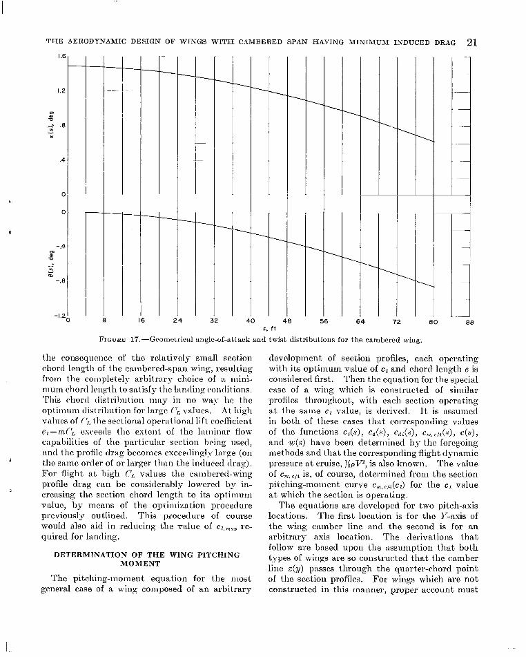
a(s) and e@) . These functions are plotted in figure 17 for the esn.niple wing.
THE FINAL WING FORM
The relations shown grnphically in figures 10, 13, and 17, together with the specificat,ion of the
CL
(b) LID variation.
FIGURE 15.-Coiicluded.
NACA 65,-618 section, fully determine the physical form of the wing for cruise a t the intixi- mum value of L I D (for the particular chord function being used). As can be seen from figure 13, the variation of the chord length along the arc span is different from an elliptical distribution, especialll- along the outer GO percent of the iirc span. From figure 17 it is seen that the opera- tiontil angles of iittack nt cruise are very sinall, due priinarily to the high :1iiiount of camber of the basic section. Only R very slight ailiount of wnshout is required, the total twist tinioiinting to
The L I D variation of the flat reference wing is plotted in figure 15(b), where the inasimum value is seen to be 37.2 a t a lift coefficient of npprosi- mately 0.35. The degree to which the efficiency of the flat wing can be improved is indicated in this same figure by the curve labeled 'LT\.4ininium- area flat wing." This L I D vnriation is for n flat-span wing which possesses a minimum chord distribution based upon the same operiitional conditions as the cambered-span wing. This minimum-area flat wing is :issunled to hiive a proper twist dist.ri bution so that, tiiiniin~~ln
0111~ -0.85O.

20 TECHNICAL REPORT R-15 2-NATIONAL AERONAUTICS AND SPACE ADMINISTRATION
0 16
4-
1 32
I
FIGURE 16.-Downwash and induced angle-of-attack distributions for the cambered wing.
induced drag is obtained. The effective area of this wing is only 1,000 square feet. It is evident that appreciable decreases in the profile drag are theoretically possible when the physical wing area is reduced.
The LID variation for the cambered-span wing is shown as the top curve in figure 15(b), where i t is seen that a maximum value of 50.0 occurs a t CL=0.315. The cambered-span wing (at least for the conditions and assumptions of this example) is more efficient than either the reference or mini- mum-area flat wings for a given lift. Although the profile drag is a significant part of the total drag a t the value of CL for that occurs in this particular example, i t is of much less inipor- tance a t the higher values of CL where the induced drag predoniinwtes.
All the cotnparisons cited are based on the use of the SACA 65r618 airfoil section and merely intli- cate the relative efficiencies of a specific cambered- span wing (circular arc, P=0.8) and a specific flat-span wing under a particular set of specified
operating conditions. Neither of these wings can be said to possess maximum efficiency in the sense of absolute values obtainable. It is possible that by use of other airfoil sections and other spanwise- camber forms, and with more optimum chord- length distributions, even higher efficiencies could be obtained with both the flat and cambered-span wings.
An additional point of interest in figure 15(b) is the value of LID for CL values greater than CL*. Even when wings are designed for operation a t C, values considerably above CL*, the LID of the cambered-span wing is still considerably greater than the of the flat-span wing, a t least for the assumed conc1it.ions of this specific example. This difference means that with the specified value of T4>, the cainbered wing could cruise much more efficiently a t high altitudes than could the flat wing. As ct increases beyond 0.7, however, the cambered wing beconies less efficient than the basic flat wing. This efficiency loss, of course, is purely
T H E AERODYNAMIC DESIGN O F VINGS WITH CAMBERED SPAN HAVING M I N I M U M INDUCED DRAG 21 I .6
1.2
m Q v -- .8 - 0
.4
0
0
b,
n
- .4 m al 0
u, m
- - -.8
-1.2
\ \
I 1
s. f t 56 64 72
FIGURE 17.-Geometrical angle-of-attack and twist distributions for the cambered wing.
the consequence of the relatively small section chord length of the cambered-span wing, resulting from the completely arbitrary choice of a niini- muin chord lcngth to satisfy the ltintling conditions. ‘I’his chord tlistrihtion may in no wily be the optitiiurii distribution for 1:trge (> v:tlucs. At high values of (\ the sectional operational lift coefficient cl=tn(\ csceetls the estent of the 1:itninar flow capabilities of the particular section being used, and the profile drag becomes exceedingly l u g e (on the saine order of or larger than the induced drag). For flight a t high CL values the cambered-wing profile drag can be considerably lowered by in- creasing the section chord length to its opt h u m value, by nieans of the optimization procedure previously outlined. This procedure of course would also aid in reducing the value of re- quired for landing,
4
3
DETERMINATION OF THE WING PITCHING MOMENT
The pitching-nioment equation for the most general case of a wing composed of an arbitrary
00 80
development of section profiles, each operating with its optimum value of el and chord length c is considered first. Then the equation for the special case of a wing which is constructed of siinilar profiles tliroughout, with each section operating itt the sanie c z value, is tlcrivetl. I t is tissumed in both of these cases that correspontling values of the functions c L ( s ) , c d ( s ) , c d z ( s ) , C , , ~ , ~ / ~ ( , S ) , c(s), and w(s) have been determined by the foregoing methods and that the corresponding flight dynamic pressure a t cruise, : :pVz , is also known. The value of is, of course, determined from the section pitching-moment curve em, c,4(cz) for the c l value a t which the section is operating.
The equations are developed for two pitch-axis locations. The first location is for the IT-asis of the wing camber line and the second is for an iirbitrary axis location. The derivations that follow are based upon the assumption that both types of wings are so constructed that the catiiber line z(y) passes through the quarter-chord point of the section profiles. For wings which are not constructed in this manner, proper account must

22 TECHNICAL REPORT R-15 2-XATIONAL AERONAUTICS AND SPACE ADMINISTRATION
be taken of the displacement distance of the local profile quarter-chord point from the spanwise camber line.
PITCHING MOMENT OF THE MOST GENERAL WING FORM
The section pitching-moment contribution.- Consider first the section witfh the quarter-chord point located a t the point (y, z ) on the span line of a cambered-span wing. This profile lies in a plane which is normal to the camber line a t (y, e) and thus makes an angle T with the vertical, where T is the slope of the tangent line a t the point. (See fig. 7 . ) A t the design operating conditions the section mill produce a pitching nionient of inten- sity Mc/4/ about the spanwise camber line. This monient is a function of e l , the operating force coefficient of the section, where
F‘ c --
l- 1 3 p v %
The component, of this moment about an axis through the quarter-chord point and parallel to the Y-axis of the camber line is Mc,4/ cos T . The force system creating this monient is shown in figure 18 for the particular case where the section chord is alinecl with the direction of the free-stream flow. For the coordinate system shown in this figure with the origin a t the center of the cainber line, the section pitching moment about the hori- zontal axis through the quarter-chord point is
M c , 4 ’ cos T= -L’2+n0’[Z’-z] (73)
mliere L’=F’ cos T and z’ is tlie distance of the
Z-axis I i‘
V - i
line-of-action of Do‘ above the Y-axis, being positive in the upward direction. The positive direction of the resulting pitching moinent is as shown in figure 18. The pitching moment of this section about the Y-axis of the airfoil is given by
My‘ = - L’x + D,’ Z’ + D l 2
and since (74)
DO’z’=D,’[z’- Z + Z ] (75)
the nionien t becomes
My‘=Mc/4’ COS +D’z (76)
Consider now the case where the pitch axis is located at any arbitrary position having coorcli- nates with respect to the Y-axis of the caniber line z p and z,, as shown in figure 19. The section moment about this axis is
,
0
M,’ = - L’[X- x,] +Do’[ 2’ - z,] + D i’ [: - z,] = -L’x+D,’[z’-z]+L’T,+D’[~-zp]
( 7 7 ) = Mc/J’ COS T + Id’s,+ D’ [z- z p ]
The subscript P denotes the nrbitrrwy axis posi- tion and z, is defined as positive when the pitch axis lies above the Y-axis of the airfoil.
When the section force coefficient c l ( s ) (eq. ( 7 2 ) ) is specified, along with the chord function c(s), the pitching rnonient of each section can be determined for either of the axis locations
Z - a x i s I L,
FIGURE 18.-Force and moiiieiit system for a n-ing sectioii at an arbitrary spanwise location.
F I G U R E 19.-3Iomc~iit relat.ioiis for an n r b i t r ~ r y asis location.

THE AERODYNAMIC DESIGN O F W I N G S WITH CAMBERED SPAN HA4VING M I N I M U M INDUCED
of equations (76) or (77) since
The section iiiotnent, inoinent coefficient, and chord-length distributions are continuous func- tions of the arc-length coordinate s.
total pitching moment of the wing, with regard to the Y-axis, is obtained by integating the con- tributions of the sections along the arc span,
, Wing pitching moment about Y-axis.-The
and substitution of My' froin equation (76) yields P
S l
3dy= f-sl [MC/?' cos r+D'z] ds (80)
I n this equation the factors are all functions of s. The niotnent MC,,' is given by equation (78), where c , , , , ~ / * is II function of the sectional force coefficient c l . The drag force D' is niatle up of two components, the profile drag Dof nnd the local induced drng D,' where
nor =CdqC (81)
D,'=P' tan ai (82)
II" = c 1qc (83)
and
As hiis heen shown previously
and
W tall 01. - - -v (S4)
i where tu is the induced velocity component
.I Thus, equation (80) can be written in the
norninl to the lifting line (the "effective" down- wash, as given by eq. (42)).
espantled form
The function cos T ( S ) can be determined as a function of y from the geoinetry of the camber
line z(y), 1 cos r= Jl+KT
DRAG 23
(S6)
and then as a function of s from the relation
From equation (87), z can also be determined as a function of s. Since all factors of the inte- grand of equation (85) are variables in the general case being considered, this integral cannot be further simplified.
Wing moment about arbitrary axis.-The wing pitching moment M p about an arbitrary axis P(xp,zp) follows directly by substitution of equation (77) into the integral
Thus,
Alternately, equation (89) can be written as
M , = A ~ , + ~ S ~ ~ ~ ~ ~ c,c cos T ~ S
PITCHING MOMENT OF A WING CONSTRUCTED OF SIMILAR PROFILES
The pitcliing-tnoinent relations for a canibered- span wing which is constructed entirely of similar profiles, all operating a t the saiiie value of the section force coefficient c 1 can now be derived.
Wing pitching moment about Y-axis.-The pitching moinent about the Y-axis of a wing with similar airfoil sections along the span can be ob- tained directly by specializing the general form of equation (85). Under the design restrictions, it follows that the chord distribution c(s) can be
24 TECHNICAL REPORT R-15 2-XATIONAL AERONAUTICS AND SPACE ADMINISTRATION
written as
(91) r c(s) =eo - r0
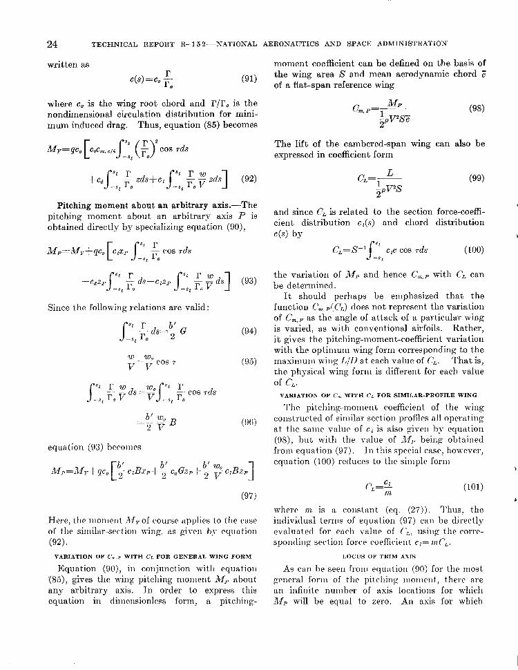
where co is the wing root chord and r/ro is the nondimensional circulation distribution for mini- mum induced drag. Thus, equation (85) becomes
Pitching moment about an arbitrary axis.-The pitching moment about an arbitrary axis P is obtained directly by spec,ializing equation (go),
Since the following relations are valid :
b' w, -- - 2 V B
-
(94)
(95)
equation (93) becomes
1 b' 6' w, 2 2 v A%=My+qc0 [g czBsp+- cdGzp+- - c f B z p
(97)
Here, the monient My of course applies to the rase of the siniiliir-section wing, its given by equation (92).
VARIATION OF C , , P WITH CI. FOR GENERAL WING FORM
Equation (go), in conjunction with equation (85), gives the wiiig pitching moment .Mp about any arbitrary axis. In order to express this equation in dimensionless form, a pitching-
moment coefficient can be defined on the basis of the wing area S and mean aerodynamic chord of a flat-span reference wing
C m , P = l Mp . (98) zpv2sz
The lift of the cambered-span wing can also be expressed in coefficient form
and since C, is related to the section force-coeffi- cient distribution c ,(s) and chord distribution 4 s ) by n
c,=s-y:, CLC cos rds ( 100)
the variation of M p and hence Cm,p with C, can be determined.
It should perhaps be emphasized that the function Cm, p(CL) does not represent the variation of Cm,p as the angle of attack of a particular wing is varied, as with conventional airfoils. Rather, it gives the pitching-moment-coefficient variation with the optiniuni wing forni corresponding to the masimum wing LjD a t each value of CL. That is, the physical wing fori11 is different for each value of c,.
VARIATION OF C , WITH CL FOR SIMILAR-PROFILE WING
The pitcliirig-inonient coefficient of the wing constructed of siniilar section profiles all operating at the same vttlue of c z is also given by equation (%), but with the value of LWp being obtained froin equation (97). In this special case, however, equation (100) reduces to the simple form
&
p -62 L - - m
b
where m is a constant (eq. (27)). Thus, the individual terms of equation (97) can be directly evaluated for each value of (;,, using the corre- sporitlinp section force coeffickit c f = mPL.
LOCUS OF TIUM AXIS
As can he seen froiii equation (90) for the most general foriii of the pitching moment, there are an infinite number of axis locations for which A l p will be equal to zero. An asis for which

T H E AERODYNAMIC DESIGN O F W I N G S WITH CAMBE RED SPAN HAVING MINIMUM INDUCED DRAG 25
Mp=O will be defined as a trim axis. A knowledge of the locus of such axes is obviously important for determining aircraft component arrangements which xvill possess satisfactory trim properties at cruise flight conditions.
For a given set of cruise flight requirements and the corresponding optimum wing form, the value of M y (eq. (90)) can be calculated and the values of the two integral factors determined. Then, the trim condition Mp=O leads to the equation
J -s, I _ --.
r which defines the locus of the trim axis, zT= zT(xT) . Since M y and the integrals are constants in this equation, the zT value for any xT location is thus determined for the trim condition.
For the case of a wing constructed of similar profiles operating a t the sanie value of e t , the locus z T = z T ( x T ) is obtained froiii equation (97),
By use of' the equations developed herein, the wing pitching nioment of tiny optimally loaded cambered-span airl'oil c m be calculated for the design flight condition. I n the g e n e i d case, thc optiiiiiiin iioricliiiieiisioii~il riiwilatioii lotitling r/r, may Iitive to be tlctcwiiilictl by thc elec~trical nnalog iiietliod and hence iiiiist be expressed in graphicti1 l'oriii. ( 'onsequently, thc cnsiiing de- sign analysis and iiionient deterinintitions will also have to be carried out graphically. Even in the particular cases where r/r, can be obtained analytically by confoimial trtttisforin:itions, the
complex integrals, so that niachine solutions are necessary.
In the particular case of the similar-profile wing, the calculation of the pitching-moment variation with lift coefficient is considerably simplified because most of the integrals are then const ants.
The locus equations (102) and (103) can be used to determine the proper location of the
3 resulting functions may result in extreniely
center of gravity of a complete aircraft configura- tion so as to optimize the longitudinal trim requirements a t cruise.
CONCLUDING REMARKS
General relations needed for the design of arbitrary cambered-span airfoils which will possess the theoretical miniinutn induced drag for specified flight conditions have been developed. These relations, however, allow the determination of the optimum wing form not only lor minimum in- duced drag, but also for the maximum attainable value of lift-drag ratio by optimizing the chord distribution of the wing.
The procedures developed can be used for the determination of the optimum wing design when a specific spanwise camber line and section pro- file are given. The camber-line shape and wing section profile that will be best for a particular set of flight requireinents depend, of course, upon the specific mission involved, and only by a series of comparative designs can the best overall wing forni be determined in any particular case. The design procedures prrscntetl, Iiowevrr, are in a form which tillows suc-h efficiency coiiiparisolis to be easily made.
It should perhaps be explicitly emphasized that cambered-span wings will not in all cases possess superior aerodynamic efficiency compared with the optiniuni flat wing of equal projected span. The relative efficiencies of flat and curved wings will depend ('rifically upon the ratio of the induced drag reduc*tion to t tic in(-reased profile drag of the c:inil)eretl wing, and the tiiagnitilde of this ratio (-an be dctcrtiiined only hy cxrrying out a series of coniptiixtive design wn:ilyses according to the niethods presented herrin.
The design procedure presented does not specifi- cally include such possible effects as interference and tip sepiirittion drags. The method is based on the assuniption that the two-dimensional sec- tional force coefficients are closely approximated by the profiles of the three-diniensional wings. For large span wings or wings with moderate spanwise camber, the procedure outlined should be quite valid within the limitations of linear lif ting-line theory. The procedure also includes the assumption that the section profiles selected for wing construction have a sufficiently large mininium thickness that they will provide ample room for housing the wing spar structure.
26 TECHNICAL REPORT R-15 2-XATIONAL AERONAUTICS AND SPACE ADMINISTRATION
The results of the illustrtitive comparison of a cambered wing with a flat wing of equal span (although neither wing has been optimized with respect to niaxiniurn lift-drag ratio) indicate that gains in operational efficiency can be secured with cambered-span wings, as compared with the effi- ciency of conventional wings currently in use, when use is made of special profiles to minimize the wing profile drag. The magnitudes of the gains attainable with cambered-span wings over
optiniuni flat wings will be smaller a t low lift coefficients due to the predoniinance of the profile drag. At higher lift coefficients, however, where the induced drag becomes a signscant factor in wing efficiency, the higher effective aspect ratio of cambered wings becomes very important for wings of limited span.
LANGLEY RESEARCH CENTER, NATIONAL AERONAUTICS AND SPACE ADMINISTR.41710N,
LANGLEY STATION, HAMPTON, VA., June 5 , 1962.
APPENDIX A THE RELATIONSHIP OF LIFT TO INDUCED DRAG FOR OPTIMALLY LOADED AIRFOILS
It can be shown (ref. 1) that for any optimally loaded lifting line of projected span 6' and pro-
and
(A5) 1 f (cambered line)=-
ducing a lift force I,, the induced drag is given by BN.4
n --[--I f L 2 2--4 b'
From equation (4), when $= 1 .O (corresponding to the condition where the projected spans of the straight and cambered wings are equal),
(AI)
k= T-' BNa (A6) where y. is the free-stream dynamic pressure and f is a constant that depends only upon the shape of the spanwise camber line z(y). and the j value for any canibered forin, when
For a straight lifting-line seglilent, the circula- d'=l.o is used to determine ki is then giver1 by tion distribution is elliptical -when the line is optimally loaded and
1 0.318 f (cambered line)=-=-- rk k
When k>1.0 , the cambered span will possess less induced drag than the optimally loaded flat span. Thus, for wings of equal projected span, the induced drag depends only upon the total lift 1,
1 and spatial distribution of the wake vorticity (whose effect is nieasured byJ), and is independent of wing area S or the associated aspect ratio
(A21 "P
Therefore
f (straight line) =-=O.318 7T (A:3)
For a cambered-span airfoil (or any other non- planar lifting system), the induced drag is so long as the wing loading is optimum. i
The need to introduce a reference area S and aspect ratio A arises in defining coefficients. (A4)
?
REFERENCES
1. Cone, Clareiicc D., Jr.: The Theory of Induced Lift 3. Abbott, Ira H.. and Voii I)oenhoff, Albert E.: Thcory of and Alininiuni Induced Drag of Nonplanar Lifting AIcGraw-Hill Book Co., Inc., 1040. Systems. SA4SA TR R-139, 1962.
2, cone, clarellcc, I)., jr,: A Theoretical ~ ~ ~ ~ ~ ~ t i ~ ~ t i ~ ~ ~ of 4. Abbott, Ira H., Van I)oellhoff, Albert E.. and StiverS;, Vortex-Sheet Deformation Behind a Highly Loaded Louis S., Jr.: Summary of Airfoil Data. NACA Wing and Its Effect on Lift. SAS.4 T S D-657, 1061.
Wing Sections.
Rcp. 824, 1945. (Superscd(~s SACA W R L-560.)
U . S G O V E R N M E N T P R I N T I N G O F F I C E . 1 3 6 4