the “a frame” rifle/shotgun/pistol rack · pdf filethe “a frame”...
TRANSCRIPT

The “A Frame” Rifle/Shotgun/Pistol Rack
The following document describes how to build the “A Frame” Rifle/Shotgun/Pistol Rack’s that were built by Major BS Walker and Striker for the Cavalier Cowboys SASS Shooting Club (www.cavaliercowboys.org). These racks were designed for cowboy action shooting but could be utilized for many different types of shooting sports. The basis of this design is a combination of design plans that we have seen at other ranges and enhancements we created to provide all of the function and features we were looking for in a range rifle/shotgun/pistol rack. We refer to this design as the “A Frame” Rack because the basic shape of the main support legs when viewed from the end are of a large capital “A”. Features of the “A Frame” Rack include: Space for 20 long guns per side, Diamond shaped holes in the lower shelf to store 8 pairs of pistols (muzzle down), upper and lower storage shelves for ammo, brass bags, etc., And holes in the upper/lower shelves for positioning a large patio umbrella for shade and weather protection.

The “A Frame” Rifle/Shotgun/Pistol Rack
Materials Lists:
All boards are treated Qty 6 8ft. x 1 1/4 x 6 in. deck boards Qty 5 8ft. x 2 x 4 in. boards Qty 1 6ft. x 1 x 6 in. board Qty 1 8ft. x 2 x 8 in. board (approx. 20 inches required) Qty 1 Box of 2 1/2 in. wood or deck screws Qty 4 Small hex head screws (used as shims) Qty 7 1/2 in. x 24 in. riser flex pipe for yard sprinklers (ie Orbit Brand) Qty 42 Shotgun hulls
Tools Required:
11 / 16 in. Spade Bit 2 1/4 in. Hole Saw Hot Glue Gun and Glue Sticks Counter Sink Bit (sized for wood / deck screws) Power Miter Saw Cordless Screw Gun
Notes: In order to prevent the boards from splitting during assembly we recommend that you drill and countersink all of the holes for the wood / deck screws. The drawings contained within this document are NOT made to scale, they are intended to give a visual representation of the given part or assembly. The design has been improved over time, several of the photographs within this document are of earlier versions of the design, so slight variances can be observed through close inspection. The instructions and drawings are all of the latest design.
The “A Frame” Rifle/Shotgun/Pistol Rack
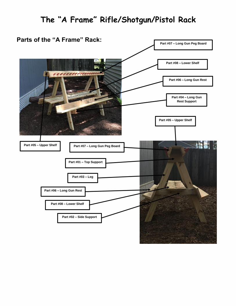
Parts of the “A Frame” Rack:
Part #04 – Long Gun
Rest Support
Part #05 – Upper Shelf
Part #06 – Long Gun Rest
Part #08 – Lower Shelf
Part #07 – Long Gun Peg Board
Part #01 – Top Support
Part #02 – Side Support
Part #03 – Leg
Part #05 – Upper Shelf
Part #06 – Long Gun Rest
Part #07 – Long Gun Peg Board
Part #08 – Lower Shelf

The “A Frame” Rifle/Shotgun/Pistol Rack
The General Steps for building the “A Frame” Rack are as follows:
1. Cut all of the lumber according to the “Cut Specifications”.
2. Build the “A” Frame Assembly.
3. Build the Long Gun Peg Board Assembly.
4. Build the Lower Shelf Assembly.
5. Stand up the “A” Frame Assemblies.
6. Attach the Long Gun Peg Board Assemblies.
7. Attach the Long Gun Rest boards.
8. Attach the Lower Shelf Assemblies.
9. Attach the Upper Shelf
10. Drill the holes in the Upper Shelf and Lower Shelf for the Umbrella
11. Add additional support screws
The “A Frame” Rifle/Shotgun/Pistol Rack
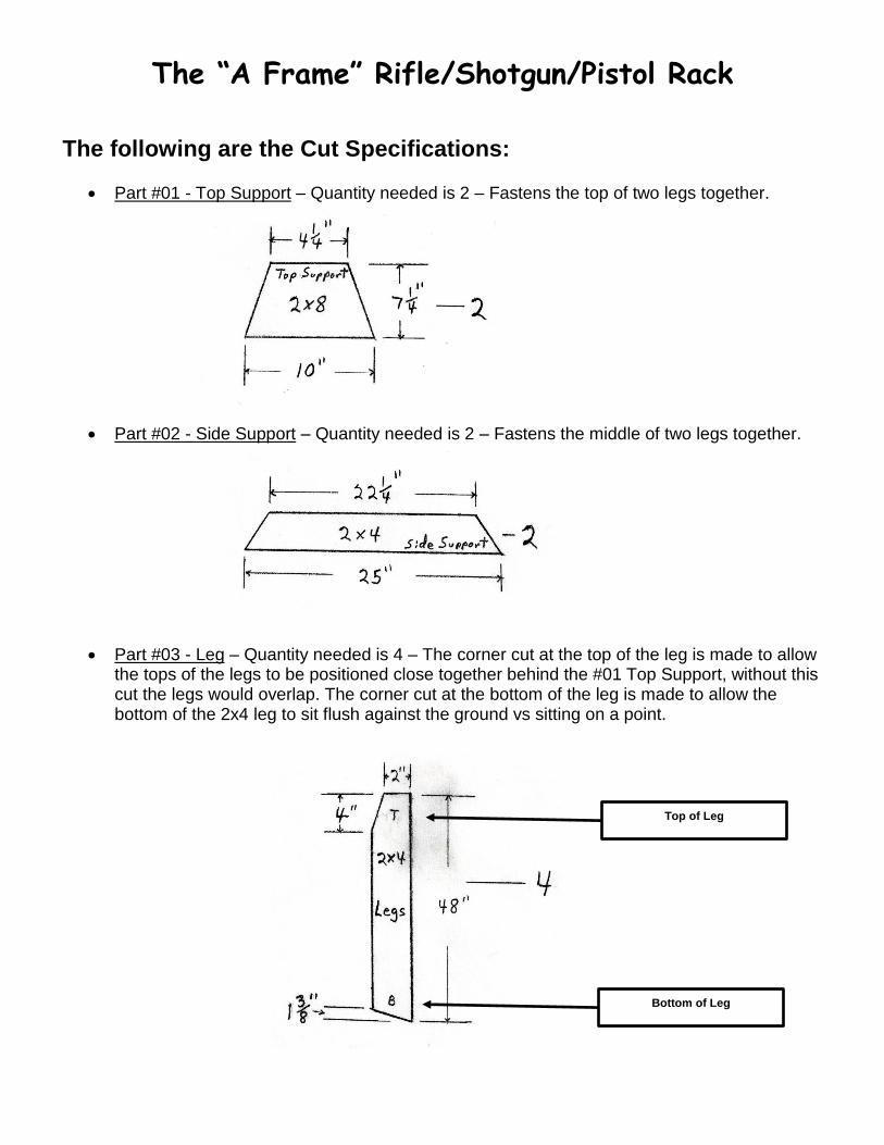
The following are the Cut Specifications:
Part #01 - Top Support – Quantity needed is 2 – Fastens the top of two legs together.
Part #02 - Side Support – Quantity needed is 2 – Fastens the middle of two legs together.
Part #03 - Leg – Quantity needed is 4 – The corner cut at the top of the leg is made to allow the tops of the legs to be positioned close together behind the #01 Top Support, without this cut the legs would overlap. The corner cut at the bottom of the leg is made to allow the bottom of the 2x4 leg to sit flush against the ground vs sitting on a point.
Top of Leg
Bottom of Leg

The “A Frame” Rifle/Shotgun/Pistol Rack
Part #04 - Long Gun Rest Support – Quantity needed is 4 – These 2x4’s are used to support the lower deck boards that make up the long gun rest supports.
Part #05 - Upper Shelf – Quantity needed is 1 – Made from 6ft. x 1 x 6 board – Board is cut to 72 inches in length.
Part #06 - Long Gun Rest – Quantity needed is 4 – Made from 8ft. x 1 1/4 x 6 in. deck boards – All 4 of these are cut to 72 inches in length.
Part #07 - Long Gun Peg Board – Quantity needed is 2 – Made from 8ft. x 2 x 4 boards – All 2 are cut to 72 inches in length.
Part #08 – Lower Shelf – Quantity needed is 2 – Made from 8ft. x 1 1/4 x 6 deck boards – All 2 are cut to 72 inches in length. The directions for cutting the triangle sized holes is later in this document.

The “A Frame” Rifle/Shotgun/Pistol Rack
Assembly:
1. “A” Frame Assembly: The first step is to build two of the “A” frame assemblies that will form the legs of the rack. For each “A” frame leg assembly you will need:
Qty 1 Part #01 - Top Support Qty 1 Part #02 - Side Support Qty 2 Part #03 - Legs Qty 2 Part #04 - Long Gun Rest Supports
Position the two legs on your work surface with the tops of the legs touching each other and the bottom of the legs approximately 36” apart. A straight edge may be useful to align the legs along the bottom. The top most outer corner of the legs should be flush with the Top Support and the outer sides of the legs should be flush with the outer edges of the Top Support and the Side Support. The Side Support is positioned 22 inches from the top of the Side Support to the flush level line of the bottom of the Legs. The Top Support and Side Support sit on top of the Legs and they should be attached to the legs first. The Long Gun Rest Supports are positioned underneath the legs, the opposite side as the Top and Side Supports. The Long Gun Rest Support is positioned perpendicular to the legs and the top of the Long Gun Rest Support is 18 inches up from the outside bottom corner of the legs, measured along the legs. Assemble the parts as shown:
Part #01 – Top
Support
Part #03 – Leg
Part #02 – Side Support Part #04 – Long Gun
Rest Support

The “A Frame” Rifle/Shotgun/Pistol Rack
Part #07 – Long Gun Peg Board
2. Long Gun Peg Board Assembly: This assembly is made out of Part #07 - Long Gun Peg Board, you will need two of these. In addition you will need 42 shotgun hulls and approximately 7 of the 1/2 in. x 24 in. riser flex pipe for yard sprinklers (ie Orbit Brand from Lowes). The general idea of making the shotgun hull peg board, is to drill an 11/16 inch hole, hot glue in a short section of the riser flex pipe and then hot glue the shotgun hull onto the riser flew pipe. The hole should be drilled as deeply as possible without coming out the back of the 2x4. We used a 11/16 inch spade bit and had to take into account the center tip of the spade bit when determining hole depth. We used a drill press with a controlled depth gauge, but there are other methods for drilling holes to a fixed depth. The length of the cut on the riser flex pipe is determined by the depth of the hole drill in the 2x4, plus the depth the riser flex pipe fits inside the shotgun hull. This should be about 3 1/2 inches to 4 inches, depending on the type of drill bit and the depth of the hull. We used an electric miter saw to cut the riser flex pipe. Once the length of pipe was determined we clamped a block of wood on the saws backrest to act as a length stop gig. The saw wanted to send the cut piece of pipe flying through the air, so we installed a deck screw into the block of wood, such that it would slide into the pipe as we moved the pipe against the stop gig, the screw kept the pipe on the saw and prevented it from being tossed. Draw a line down the center of the 2x4 the full 72 inches of its length. Now make a mark on
this line at the midpoint (36 inches). This intersection will be the first hole. The place another
mark 3 1/2 inches on the center line in each direction from this center mark. You should end
up with the center hole, plus 10 other holes on each side of it for a total of 21 holes.
We used a block of wood clamped to the table of the drill press as a guide that we slid the
2x4 along. After drilling the center hole, with the drill bit still in the hole, we extended the line
that we had drawn for the center hole, onto the wood clamped to the table of the drill press.
This line was then used to align each of the other holes.
(Drawing is not to scale and not intended to show all the drill holes)
The “A Frame” Rifle/Shotgun/Pistol Rack
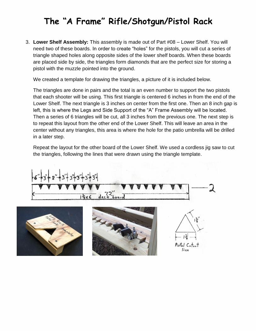
3. Lower Shelf Assembly: This assembly is made out of Part #08 – Lower Shelf. You will
need two of these boards. In order to create “holes” for the pistols, you will cut a series of
triangle shaped holes along opposite sides of the lower shelf boards. When these boards
are placed side by side, the triangles form diamonds that are the perfect size for storing a
pistol with the muzzle pointed into the ground.
We created a template for drawing the triangles, a picture of it is included below.
The triangles are done in pairs and the total is an even number to support the two pistols
that each shooter will be using. This first triangle is centered 6 inches in from the end of the
Lower Shelf. The next triangle is 3 inches on center from the first one. Then an 8 inch gap is
left, this is where the Legs and Side Support of the “A” Frame Assembly will be located.
Then a series of 6 triangles will be cut, all 3 inches from the previous one. The next step is
to repeat this layout from the other end of the Lower Shelf. This will leave an area in the
center without any triangles, this area is where the hole for the patio umbrella will be drilled
in a later step.
Repeat the layout for the other board of the Lower Shelf. We used a cordless jig saw to cut
the triangles, following the lines that were drawn using the triangle template.
The “A Frame” Rifle/Shotgun/Pistol Rack
Time for Final Assembly:
1. Final Assembly can be completed at the range with a cordless drill and an assistant or two, this allows for the rifle rack to be easily transported.
2. Stand up the two “A” Frame assemblies, approximately 4 feet apart, with the Top Support and Side Support boards facing out, away from each other.
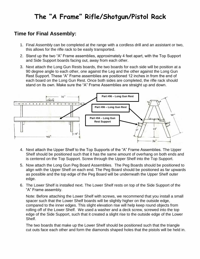
3. Next attach the Long Gun Rests boards, the two boards for each side will be position at a 90 degree angle to each other, one against the Leg and the other against the Long Gun Rest Support. These “A” Frame assemblies are positioned 12 inches in from the end of each board on the Long Gun Rest. Once both sides are completed, the rifle rack should stand on its own. Make sure the “A” Frame Assemblies are straight up and down.
4. Next attach the Upper Shelf to the Top Supports of the “A” Frame Assemblies. The Upper Shelf should be positioned such that it has the same amount of overhang on both ends and is centered on the Top Support. Screw through the Upper Shelf into the Top Support.
5. Now attach the Long Gun Peg Board Assemblies. The Peg Boards should be positioned to align with the Upper Shelf on each end. The Peg Board should be positioned as far upwards as possible and the top edge of the Peg Board will be underneath the Upper Shelf outer edge.
6. The Lower Shelf is installed next. The Lower Shelf rests on top of the Side Support of the “A” Frame assembly.
Note: Before attaching the Lower Shelf with screws, we recommend that you install a small spacer such that the Lower Shelf boards will be slightly higher on the outside edge, compared to the inner edges. This slight elevation rise will help keep round objects from rolling off of the Lower Shelf. We used a washer and a deck screw, screwed into the top edge of the Side Support, such that it created a slight rise to the outside edge of the Lower Shelf.
The two boards that make up the Lower Shelf should be positioned such that the triangle cut outs face each other and form the diamonds shaped holes that the pistols will be held in.
Part #06 – Long Gun Rest
Part #06 – Long Gun Rest
Part #04 – Long Gun
Rest Support

The “A Frame” Rifle/Shotgun/Pistol Rack
The pair of board should be positioned such that there is the same amount of overhang on each end of the rack and the boards should be positioned so that there is the same amount of space between the outer edge of the shelf and the Leg Boards.
7. The next step is optional. We drilled a 2 and 1/4 inch hole in the Upper and Lower Shelves so that a large patio umbrella could be used to provide sun and rain protection to the items stored on the rifle rack. Locate the center of the Upper Shelf, both in length and width. Then drill a hole at that center location with a hole saw or similar tool. Next use a plumb bob or similar device, suspended down from the center of the hole just drill in the Upper Shelf, to locate the position on the Lower Shelf. Using this method assures the patio umbrella will be positioned straight up and down.
8. The last step is to add some additional deck screws into the rifle rack to increase stability and strength. Along the outer edge of the Upper Shelf, drill pilot holes at an angle such that the holes will go down into the Peg Board. Place screws along both side about every 20 inches or so. Next the two deck boards that make up the Long Gun Rest, the boards are formed into a L shaped configuration. Drill pilot holes such that they go through the width of one board at the point of the L and into the width of the other board. Place screws every 20 inches or so.