the 3d mapping preparation using 2d/3d cameras for mobile ... filethe 3d mapping preparation using...
TRANSCRIPT

«Искусственный интеллект» 4’2008 512
6R УДК 681.3.5
Hubert Roth1, Anatoly Sachenko2, Vasyl Koval 2, Joochim Chanin1,Oleh Adamiv 2, Viktor Kapura2 1University of Siegen, Siegen, Germany 2Research Institute of Intelligent Computer Systems, Ternopil National Economic University, Ternopil, Ukraine [email protected], [email protected]
The 3D Mapping Preparation using 2D/3D Cameras for Mobile Robot Control* The generalized frame of autonomous robot control system is represented and the data preparation for the simultaneous localization and mapping (SLAM) by using new type of 3D sensor is described. Also the developed data structure for data communication between robot units, and the protocol for client-server interaction, and an algorithm for the data communication of client-server protocol packages allowing to control by mobile robot in unstructured environment, and their application on real-scaled mobile robot are presented in this paper.
Introduction Mobile robots (MR) as universal technical systems that can provide mechanical activity
are one of the modern trends of scientific research in the field of robotics. Widespread applications of intelligent mobile robots are different fields of human activity is a confirmation of the timeliness of the researches. These applications are oriented towards in-door environments constructed by humans and for external unstructured environments, where these systems are used in ground, aerial, space or under-water oriented applications. There is an especially important application of mobile robots in aggressive unstructured environments that are dangerous or impossible for human activity such as man-caused catastrophes, fire or terrorist acts.
Nowadays there are a lot of known architectural decisions for MR navigation on the executive, tactical and strategic level in static environments [1-4]. If the environment is unstruc-tured one may either provide sophisticated planning, decision making and control schemes or one may force structure onto the environment. Therefore the analysis of such decisions will allow to design optimum configuration of interrelations of the main MR modules for providing obstacle avoidance navigation in dynamic unstructured environments. A lot of mobile robot structures are mostly related to static priory known environments or at list are standalone that need to be combined in order to reach the joint benefit for MR navigation in unstructured environment. For this purpose it is proposed the generalized structure of the autonomous mobile robot control system presented on Fig. 1. that is a basis for providing of the MR navigation in un-structured environment and shows the general subtasks interconnection and for MR navigation.
Taking into account the productivity of computing means that are necessary for func-tioning of MR, the MR subsystems can be realized using monoprocessor systems or the specia-lized tools, for example, using multiprocessor subsystem. The monoprocessor systems based on the personal computers (PC) compared with the specialized tools have the less computing speed
* The authors are grateful for the support of the Ministry of Education and Science of Ukraine and International Bureau of the Federal Ministry of Education and Research of Germany, German Aerospace Center within the International research project 0108U004785 “Development of stereovision methods and devices for autonomous navigation of mobile robots”.
The 3D Mapping Preparation using 2D/3D Cameras for Mobile Robot Control
«Штучний інтелект» 4’2008 513
6R
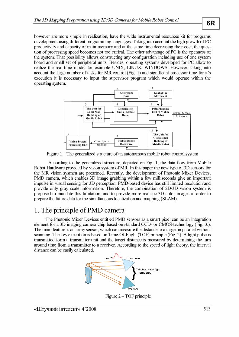
however are more simple in realization, have the wide instrumental resources kit for programs development using different programming languages. Taking into account the high growth of PC productivity and capacity of main memory and at the same time decreasing their cost, the ques-tion of processing speed becomes not too critical. The other advantage of PC is the openness of the system. That possibility allows constructing any configuration including use of one system board and small set of peripheral units. Besides, operating systems developed for PC allow to realize the real-time mode, for example UNIX, LINUX, WINDOWS. However, taking into account the large number of tasks for MR control (Fig. 1) and significant processor time for it’s execution it is necessary to input the supervisor program which would operate within the operating system.
Figure 1 – The generalized structure of an autonomous mobile robot control system
According to the generalized structure, depicted on Fig. 1, the data flow from Mobile Robot Hardware provided by vision system of MR. In this paper the new type of 3D sensors for the MR vision sysmen are presetned. Recently, the development of Photonic Mixer Devices, PMD camera, which enables 3D image grabbing within a few milliseconds give an important impulse in visual sensing for 3D perception. PMD-based device has still limited resolution and provide only gray scale information. Therefore, the combination of 2D/3D vision system is proposed to inundate this limitation, and to provide more realistic 3D color images in order to prepare the future data for the simultaneous localization and mapping (SLAM).
1. The principle of PMD camera
The Photonic Mixer Devices entitled PMD sensors as a smart pixel can be an integration element for a 3D imaging camera chip based on standard CCD- or CMOS-technology (Fig. 3.). The main feature is an array sensor, which can measure the distance to a target in parallel without scanning. The key execution is based on Time-Of-Flight (TOF) principle (Fig. 2). A light pulse is transmitted form a transmitter unit and the target distance is measured by determining the turn around time from a transmitter to a receiver. According to the speed of light theory, the interval distance can be easily calculated.
Figure 2 – TOF principle
The Unit for Local Map Building of
Mobile Robot
Localization Unit of Mobile
Robot
Path Planning Unit of Mobile
Robot
Vision System readings
Control Signals to Actuators
Goal of the Movement
The Unit for Global Map Building of
Mobile Robot
Vision System
Processing Unit Mobile Robot
Hardware
Knowledge Base
1 2
3 4
5 7
8
6

Roth H., Sachenko A., Koval V., Chanin J., Adamiv O., Kapura V.
«Искусственный интеллект» 4’2008 514
6R
The PMD chip is a prominent component, its pixel provides the depth information of corresponding point in the object plane. The PMD has the advantages of fast imaging and excellent depth information for scene capture. This camera can also enable fast optical sensing and demodulation of incoherent light signals in one component. It additionally provides both the intensity as well as the distance in each pixel. Currently, the PMD sensor devices provide the resolutions of 48x64, 64x16 and 160x120 pixels. A common modulation frequency is 20 MHz, which results in an unequivocal distance range of 7,5 to 40 meters. The principle of how a simplified PMD sensor calculates the distance between obstacle and camera is to analyze a phase shift. The depth data results from the phase shift of the out-coming and the incoming signals. The equation for the autocorrelation is:
T
dttxtxc0
)()()( , (1)
where T is time of integration, the correlation is done using four samples 41...CC with time interval of 4T and phase shift )( .
)arctan(42
31
CCCC
. (2)
The distance )(d can be easily calculated to:
mod
0
.4.f
cd
, (3)
where 0c is the speed of light and modf is the modulation frequency, a common value of the modulation frequency is 20MHz.
a) b) c)
Figure 3 – PMD camera a) A2; b) 19k; c) PMD sensor The light source capability and the noise suppression Ideally, powerful light source is desired for long distance detection. In reality the
construction of the light source is mainly limited by the maximum switching frequency and the power dissipation. For detection range of 40 meter, a high power light module is required. From construction point of view the laser and LEDs light source are both capable according to their high switching frequency and low power consumption.
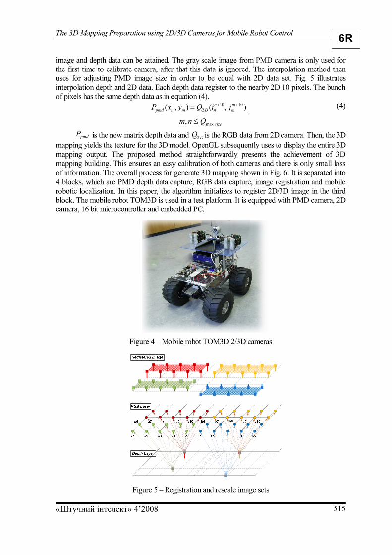
2. Image registration The 3D mapping is acquired by a movement of mobile robot name “TOM3D” (Tele
Operated Machine with 3D PMD-camera) (Fig. 4). It can be used for high performance indoor and outdoor off-road. When the robot is moving through the scene, the 3D geometry is collected by 2 sources camera at the same time. The depth data is obtained from PMD while texture is mapped from 2D camera. The resolution of the 3D data from PMD camera (64*48) is 10 times less than 2D camera (640*480). By using both of these two cameras, high resolution, gray scale
The 3D Mapping Preparation using 2D/3D Cameras for Mobile Robot Control
«Штучний інтелект» 4’2008 515
6R
image and depth data can be attained. The gray scale image from PMD camera is only used for the first time to calibrate camera, after that this data is ignored. The interpolation method then uses for adjusting PMD image size in order to be equal with 2D data set. Fig. 5 illustrates interpolation depth and 2D data. Each depth data register to the nearby 2D 10 pixels. The bunch of pixels has the same depth data as in equation (4).
),(),( 10102
mm
nnDmnpmd jiQyxP
. (4)
sizeQnm max,
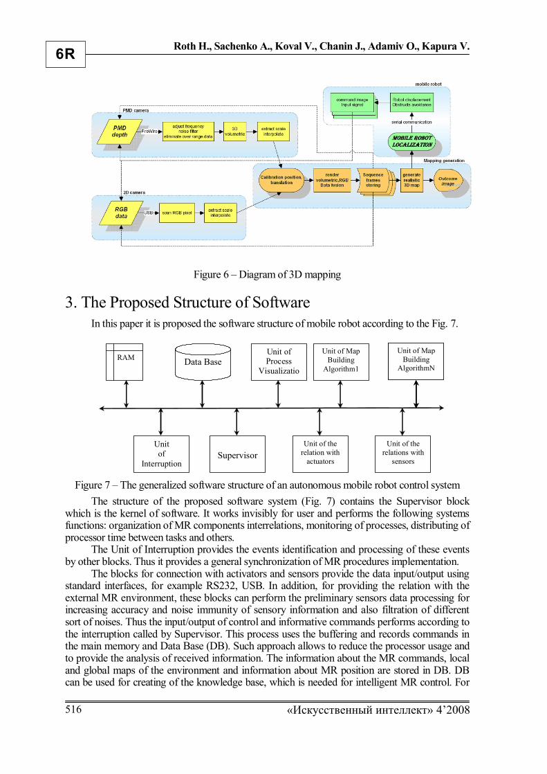
pmdP is the new matrix depth data and DQ2 is the RGB data from 2D camera. Then, the 3D mapping yields the texture for the 3D model. OpenGL subsequently uses to display the entire 3D mapping output. The proposed method straightforwardly presents the achievement of 3D mapping building. This ensures an easy calibration of both cameras and there is only small loss of information. The overall process for generate 3D mapping shown in Fig. 6. It is separated into 4 blocks, which are PMD depth data capture, RGB data capture, image registration and mobile robotic localization. In this paper, the algorithm initializes to register 2D/3D image in the third block. The mobile robot TOM3D is used in a test platform. It is equipped with PMD camera, 2D camera, 16 bit microcontroller and embedded PC.
Figure 4 – Mobile robot TOM3D 2/3D cameras
Figure 5 – Registration and rescale image sets
Roth H., Sachenko A., Koval V., Chanin J., Adamiv O., Kapura V.
«Искусственный интеллект» 4’2008 516
6R
Figure 6 – Diagram of 3D mapping
3. The Proposed Structure of Software
In this paper it is proposed the software structure of mobile robot according to the Fig. 7.
Figure 7 – The generalized software structure of an autonomous mobile robot control system
The structure of the proposed software system (Fig. 7) contains the Supervisor block which is the kernel of software. It works invisibly for user and performs the following systems functions: organization of MR components interrelations, monitoring of processes, distributing of processor time between tasks and others.
The Unit of Interruption provides the events identification and processing of these events by other blocks. Thus it provides a general synchronization of MR procedures implementation.
The blocks for connection with activators and sensors provide the data input/output using standard interfaces, for example RS232, USB. In addition, for providing the relation with the external MR environment, these blocks can perform the preliminary sensors data processing for increasing accuracy and noise immunity of sensory information and also filtration of different sort of noises. Thus the input/output of control and informative commands performs according to the interruption called by Supervisor. This process uses the buffering and records commands in the main memory and Data Base (DB). Such approach allows to reduce the processor usage and to provide the analysis of received information. The information about the MR commands, local and global maps of the environment and information about MR position are stored in DB. DB can be used for creating of the knowledge base, which is needed for intelligent MR control. For
RAM Data Base
Unit of Process
Visualization
Unit of Map Building
Algorithm1
Unit of
Interruption
Supervisor
Unit of the relation with
actuators
Unit of the relations with
sensors
Unit of Map Building
AlgorithmN

The 3D Mapping Preparation using 2D/3D Cameras for Mobile Robot Control
«Штучний інтелект» 4’2008 517
6R
example, it is important for MR control to analyze the stored in DB data for providing the possibility to return to previous position in the case of deadlock condition and choice other trajectory of movement.
Unit of Process Visualization provides monitoring of MR functional activity on the screen of display. Such mode is necessary during debugging of main procedures of MR functioning. In the real conditions the block of monitoring should be turned off for increasing the general productivity of computing means.
The blocks of algorithms implementation provide the realization of processes for construc-tion of local and global maps of environment, construction of MR motion trajectory, localization, selecting of maneuvers for movement and analysis and processing of input data. For performance of such algorithms processor time is provided. Performance of each algorithm is completed by the program interruption call and request to Supervisor with the message about the end of pro-cedure of algorithm performance. On the basis of interruption Supervisor determines the sequen-ce of performance of procedures for MR functioning, which initialized by the new interrupt.
4. Database Structure
It is important to identify the data structure and to analyze the input data flow from robot sensors for programming of the methods of the map building of environment based on PMD camera [5-8], for map building of mobile robot. For development of data structure it is expected to use a relational data model (Fig. 8), that has advantages: convenience of presentation of data structures as two-dimensional table; flexibility of the data processing in a table form; exactness (groups relations between tables have exact maintenance and submit to the mathematical methods of treatment with the use of algebra of relations); secrecy; clarity (relational presentation of data gives the clear picture of relationships attributes from the different relations and files); independence and expansibility of data (it is easily to add and delete the new corteges and relations in the relational database); there is a facility for easily of data management; clarity and evidentness of data presentation; possibility to design of hierarchical and nets data models for data structures [9], [10]. In addition, the relational data structures have strongly developed level of abstractions of mathematical tool (relational algebra, numeral methods of group’s relations treatment, predicative logic and others).
Figure 8 – Relational data structure
5. Protocol for Client-Server Interaction The communication between Supervisor and Sensory subsystem and Subsystem of
activators of MR is carried out on a client-server principle. Such organization of communications is predefined by the necessity of distributing of calculable powers between the tasks of data acquisition which can be realized on the specialized facilities, and tasks of top level, which will be realized on PC. Co-operation between server and client parts could be provided by the specialized protocol of data exchange that has a certain structure (Table 1), that is modification of protocol presented in [11].

Roth H., Sachenko A., Koval V., Chanin J., Adamiv O., Kapura V.
«Искусственный интеллект» 4’2008 518
6R
Taking into account the real time, in which MR works, it is expected to provide functioning of protocols in the "silent" mode. In this mode the MR Sensory subsystem does not give confirmation of client’s instructions execution. Such approach provides minimum time for treatment of packets of client-server co-operation.
At the messages passing from a server to the client, the packets are transmitted periodically with state information about MR activators and with sensors data. In a case of using protocol for the transmission of RGB data from PMD camera with resolution 160х120 pixels, it is necessary such quantity of data, which must be transmit by one packet through an interface and equal a 57600 byte. At that every pixel is presented by 3 bytes of colors without application of procedures of compression. For this purpose it is enough to select 2 bytes of data (is equal to the maximum up to 65536 bytes which can be transmitted by one packet) for the component «quantity of transmitting bytes» of structures of packet of protocol.
If more information in client-server protocol of co-operation is needed, it is necessary to extend a greater quantity byte for component «quantity of transmitting bytes» in the structure of protocol packet.
In the case of transmitting messages from the client to server the commands structure in a packet is defined (Table 2). In order to control the functioning of the client-server protocol the client must periodically send selfsupervisory packet with the command «PULSE» to the server in the case of absence of MR control commands. If the control commands of client or commands «PULSE» are absent, a robot automatically stops all engines that can renew the work only after receiving a package from client. Thus, the algorithm of client-server co-operation can be represented by the generalized flow diagram (Fig. 9).
Table 1 – The Structure of Protocol Packet for MR Client-Server Interaction Component Bytes Value Description
Caption 2 0хFA, 0xFB Caption of the packet is identically as for server as for client
Quantity of transmitting bytes
1 N+2 Quantity of transmitting bytes, including check sum
Data N Commands Client’s commands or server’s information Check sum 2 Calculated Check sum of packet
Table 2 – The Structure of Commands Transmitting from Client to Server Component Bytes Value Description
Caption 2 0хFA, 0xFB Caption of the packet is identically as for server as for client
Quantity of transmitting bytes
1 N+2 Quantity of transmitting bytes, including check sum
Number of client’s command
1 0-255 Number of client’s command to server
Type of argument (depend from type of
command)
1 0x3B 0x1B 0x2B
Type of command’s argument: – positive integer; – negative integer; – string.
Argument N Data Argument of command Check sum 2 Calculated Check sum of packet calculated during
transmitting of the packet
6. Application of the Proposed Approach
Experimental researches were carried out using the mobile robot TOM3D with a test plat-form that is equipped with PMD camera, 2D camera and embedded PC and also using a platform of mobile robot Pioneer P2-DX of the ActivMedia Company [11], that two driving-wheels placed on one axle and one selforienting wheel placed on the back-end of robot and is a balance of it.

The 3D Mapping Preparation using 2D/3D Cameras for Mobile Robot Control
«Штучний інтелект» 4’2008 519
6R
Figure 9 – Generalized algorithm of client-server protocol work
Figure 10 – Source listing of Matlab subprogram

Roth H., Sachenko A., Koval V., Chanin J., Adamiv O., Kapura V.
«Искусственный интеллект» 4’2008 520
6R
For programming and researches of the offered structures with the purpose to control by a mobile robot the programming software Matlab® v.6.5 Release 13 were used, created by the firm of The Math Works Inc., which is a world standard in the region of scientific and technical calculations [12-14]. The choice of package of Matlab is predefined by its advantages [15-17]. The created software of the Matlab provides reading, recording and calculating of checks sums for the transmission of commands packages in mentioned protocol depicted on Fig. 10. Conclusion
The 3D Mapping Preparation using new type of 3D sensor for Mobile Robot Control is presented in this paper.
Another results of the researches that is presented in this paper is the developed structure of top level software for mobile robot control using the analysis of informative threads between the programming units that allows to present data on datalogical levels for building of the mobile robot map of the environment and also adapting of the client-server protocol, which provides data interaction for MR control. Taking into account the universality of the operating systems like Windows, UNIX, LINUX that use processor time for own necessities, it is reasonable to implement the top levels software using high-level languages, while communication subsystems with the peripheral devices and sensors – on microprocessors.
Fig. 11 (a) and (b) show the raw data from 2D/3D cameras before enhancement. Fig. 11 (c) demonstrates the registered image. It can be seen that the 3D image has more texture information, which is better than using the information only from 2D or 3D camera. However, the texture of registered image seems lacking from the raw data due to the differentials of rescale and quality of 2D/3D cameras. The quality of output will be improved by the better quality of 2D camera and increasing pixel of PMD camera in the upcoming future. The schemes of the 3D preparation image will be used in order to generate the future simultaneous localization and mapping.
a) b) c)
Figure 11 – Registration image a) Image from 2D camera; b) Depth data from PMD Camera; c) Registered image.
References 1. Golovko V.A., Neurointelligence: Theory and Applications. Vol. 2. – Brest: Brest Polytechnic Institute. – 1999,
227 p. 2. Castellanos J., Tardos J. Mobile robot localization and map building: a multisensor fusion approach. – Boston
Kluwer Acafemic Publishers, 1999. – 205 p. 3. Moshkin V.I., Petrov A.A., Titov V.S. The robot Vision. – M.: Mashinostroenie, 1990. – 227 p. 4. Spynu G.A. Robots with Artificial Intelligence. – K.: Tehnika, 1989. – 111 p.

The 3D Mapping Preparation using 2D/3D Cameras for Mobile Robot Control
«Штучний інтелект» 4’2008 521
6R
5. Koval V. Sensor Fusion of the Structured Light and Videocamera for Mobile Robot Control. – Artificial Intelligence. – 2004. – № 1. – Р. 52-59.
6. Koval V. The Method of Mobile Robot Obstacle Detection Using Sensor Fusion of Heterogeneous Sensors // Automated Control Systems and Devices. – Kharkov (Ukraine), 2004. – Issue 126. – Р. 128-135.
7. Koval V. The improved method of local area map building for mobile robots // The scientific journal of Pulyuj State Technical University. – 2003. – Vol. 8, № 2. – P. 80-88.
8. Koval V., Turchenko V., Sachenko A. Infrared sensor data correction for local area map construction by a mobile robot / The Lecture Notes in Artificial Intelligence. – LNAI2718, Springer-Verlag, Berlin Heidelberg, 2003. – P. 306-315.
9. Deit C. Introduction to relative data bases. – Sankt Petersburg: Publishing house "Vilyams", 2001. – 1072 p. 10. Conolli T., Begg K. Data bases. Design, realization and support. Theory and practice. – Sankt Petersburg:
Publishing house "Vilyams", 2003. – 1436 c. 11. Режим доступу: http://www.robotsactivmedia.com. 12. Serhiyenko A. Digital signal processing. – Sankt Petersburg: Publishing house "Piter", 2003. – 608 p. 13. Koniyshenko V. Matlab. The language of technical calculation. Calculating, visualisation, programming. –
2000. – 74 p. 14. Diakonow V., Kruglov V. Matlab. Analysis, identification and modelling of systems. Special reference book. –
Sankt Petersburg: Publishing house "Piter", 2002. – 448 p. 15. The MathWorks and Xilinx Plans URL web page: http://www.mathworks.com/company/pressroom/index.shtml. 16. Xilinx Alliance tools URL web page: http://www.xilinx.com/xlnx/xil_prodcat_landingpage.jsp?title=ISE+Alliance. 17. Aseeri M.A., Sobhy M. I., Alkouny A.A. Field programmable gate array (FPGA) as a new approach to imple-
ment the chaotic generators URL http://www.techonline.com/community/tech_group/34222. 18. Miachev A. Personal computers: short encyclopaedic reference book. – Moscow: Publishing house “Finance and
statistics”, 1992. – 384 p. 19. Режим доступу: http://www.usb.org. Hubert Roth, Анатолий Саченко, Василий Коваль, Joochim Chanin, Олег Адамив, Виктор Капура Подготовка 3D отображения с использованием 2D/3D камер для управления мобильным роботом Представлена обобщенная структура автономной системы управления роботом и описана подготовка данных для одновременной локализации и отображения (SLAM) с использованием нового вида 3D датчика. В статье также описаны разработанная структура данных для связи между автоматическими модулями, протокол для серверного и клиентского взаимодействия и алгоритм обмена пакетами данных на основе технологии клиент-сервер для управления мобильным роботом в неструктурированной среде, а также их использование на работающем мобильном роботе. Hubert Roth, Анатолій Саченко, Василь Коваль, Joochim Chanin, Олег Адамів, Віктор Капура Підготовка 3D відображення з використанням 2D/3D камер для управління мобільним роботом Представлено узагальнену структуру автономної системи управління роботом та описано підготовку даних для одночасної локалізації і відображення (SLAM) з використанням нового виду 3D датчика. В статті також описані розроблена структура даних для зв’язку між автоматичними модулями, протокол для серверної та клієнтської взаємодії та алгоритм обміну пакетами даних на основі технології клієнт-сервер для управління мобільним роботом в неструктурованому середовищі, а також їх застосування на працюючому мобільному роботі.
Статья поступила в редакцию 29.07.2008.