thank you for purchasing this factory service manual on ... 4410... · 2.1.10 space motor control...
TRANSCRIPT

Thank You for purchasing this
Factory Service Manual on EBAY from PCTECHINFO!
Click Here for more Factory Service Manuals for other Computer and Printer / Copier Manufacturers from PCTECHINFO!

1
PACEMARK 4410PRINTER
Service Manual

2 /
PREFACE
This maintenance manual describes how to maintain the Pacemark 4410 printerin the field.This manual is for customer engineers.For further information, refer to the Users Manual for handling or operating the equipment.
3 /
CONTENTS
1. CONFIGURATION ..................................................................................... 51.1 Basic System Configuration............................................................... 51.2 Printer Specifications ......................................................................... 61.3 Option Specifications ......................................................................... 71.4 Basic Specifications ........................................................................... 8
2. THEORY OF OPERATION ........................................................................ 112.1 Electrical Operation ........................................................................... 11
2.1.1 Summary ................................................................................................. 112.1.2 Microprocessor and the peripheral circuit ............................................... 112.1.3 Initialization .............................................................................................. 202.1.4 Interface control ....................................................................................... 212.1.5 Parallel Interface Control ......................................................................... 212.1.6 Serial Interface ........................................................................................ 222.1.7 Printing operation .................................................................................... 232.1.8 Printhead control ..................................................................................... 242.1.9 Print Compensation Control .................................................................... 262.1.10 Space motor control ................................................................................ 262.1.11 Line feed .................................................................................................. 272.1.12 Bail, tractor switching, AG, ribbon motor control ..................................... 282.1.13 Operation Panel ...................................................................................... 292.1.14 Alarm circuits ........................................................................................... 312.1.15 Power supply circuit ................................................................................ 33
2.2 Mechanical Operation ........................................................................ 342.2.1 Printhead mechanism and operation ....................................................... 342.2.2 Spacing operation ................................................................................... 362.2.3 Head gap adjusting ................................................................................. 372.2.4 Ribbon drive ............................................................................................ 402.2.5 Paper Feed Mechanism .......................................................................... 412.2.6 Bail Feed Mechanism .............................................................................. 452.2.7 Paper End Detection Mechanism ............................................................ 47
3. PARTS REPLACEMEN T........................................................................... 493.1 Precautions for Parts Replacement ................................................... 493.2 Parts Layout....................................................................................... 523.3 How to Change Parts......................................................................... 53
3.3.1 Cover-Assy-Access / Cover-Assy-Side (R) / Cover-Assy-Side (L) /Cover-Assy-Front / Frame-Assy-Rear / Plate-Front (stuck) ................ 54
3.3.2 Printer Unit .............................................................................................. 553.3.3 Control Block [Control Board (PMA Printed Board),
Driver Board (PDA Printed Board)] ....................................................... 563.3.4 Power Supply Assy ................................................................................. 573.3.5 PG Cooling Fan ....................................................................................... 583.3.6 I/F Board (PHA Printed Board) ................................................................ 593.3.7 AG Board (PGA Printed Board) / Connector Cord .................................. 603.3.8 AG Motor Assy ........................................................................................ 613.3.9 Mini Pitch Belt .......................................................................................... 623.3.10 Tractor Change Motor Assy .................................................................... 633.3.11 Bail Motor Assy ....................................................................................... 643.3.12 LF Motor Assy ......................................................................................... 65
4 /
3.3.13 Head Cooling Fan 1 ................................................................................ 663.3.14 Head Cooling Fan 2 ................................................................................ 673.3.15 Space Motor ............................................................................................ 683.3.16 Operator Board (POA Printed Board) ...................................................... 693.3.17 Ribbon Feed Assy ................................................................................... 703.3.18 Printing Head ........................................................................................... 713.3.19 Head Cable ............................................................................................. 723.3.20 Ribbon Protector ..................................................................................... 733.3.21 Space Motor Fan ..................................................................................... 743.3.22 Junction Board ........................................................................................ 753.3.23 Cover Open Switch Assy / Ribbon Rotation Sensor ............................... 763.3.24 Interlock Switch / Interlock Switch Cord Assy ......................................... 773.3.25 Knob Bracket Assy .................................................................................. 783.3.26 Space Belt ............................................................................................... 793.3.27 AG Sensor Frame / Start Searching Sensor ........................................... 803.3.28 Paper Jam Sensor Assy / Bail PE Sensor Assy ...................................... 813.3.29 Sprocket Assy (L) (R) (Front Tractor) ...................................................... 823.3.30 Sheet Feeder Assy (L) Rear / Sheet Feeder Assy (R) Rear ................... 833.3.31 Bail Assy .................................................................................................. 86
4. ADJUSTMENTS ........................................................................................ 87
5. CLEANIG AND LUBRICATIO N ................................................................ 945.1 Cleaning............................................................................................. 945.2 Lubrication ......................................................................................... 96
6. TROUBLESHOOTING AND REPAI R ....................................................... 1046.1 Items to Check Before Repair............................................................ 1046.2 Troubleshooting Table ....................................................................... 1046.3 Lamp and LCD Display ...................................................................... 1056.4 Part Layout ........................................................................................ 1096.5 Connection ........................................................................................ 111
7. PARTS LIST .............................................................................................. 112
APPENDIX A ................................................................................................... XXXAPPENDIX B ................................................................................................... XXXAPPENDIX.C ................................................................................................... XXX
5
Rib
bon
feed
mot
or
AG mot
orPo
wer
sup
ply
FAN
FUSE
hol
der
HEA
DFA
N
Mot
or/S
enso
r PC
BPo
wer
sup
ply
unit
Pape
r wid
th s
enso
r
Prin
t hea
dBa
il PE
sen
sor
Hea
d dr
iver
PC
B
Mai
n co
ntro
l/M
otor
driv
er P
CB
Inte
rface
boa
rd(O
ptio
n)
Inte
rface
/Mot
or/S
enso
r PC
B
RS2
32C
I/FIE
EE 1
284
I/F
Bail
mot
or
Trac
tor
chan
gem
otor
LF mot
or
Hea
dFA
N
Bail
posi
tion
SW
Trac
tor c
hang
e SW
Fron
t PE
SW
Rea
r PE
SW
Pape
r jam
sen
sor
Pape
r top
sen
sor
AG s
enso
r coi
l
LCD
Ope
ratio
n pa
nel P
CB
AC s
ourc
e
SP FAN
SP mot
or
Cov
er o
pen
SW
Rib
bon
jam
sen
sor
AG
sens
orPC
B
Inter lock SW
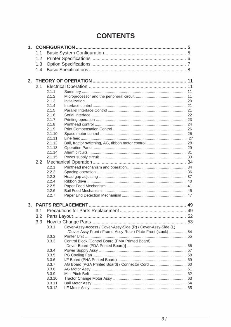
1. CONFIGURATION
1.1 Basic System Configuration
The basic system configuration of Pacemark 4410 is illustrated in Figure 1.1.
Fig
ure
1.1

6
1.2 Printer Specifications
This printer unit is composed with the following hardware.
• Printer mechanism• Main control/Motor driver board• Head driver board• Interface/Motor/Sensor board (including IEEE 1284 bidirectional parallel interface and RS-
232C serial interface)• Motor/Sensor and AG sensor boards• Operation panel board• Power supply unit• Covers
Figure 1-2 show the printer unit configuration.
Figure 1.2
7
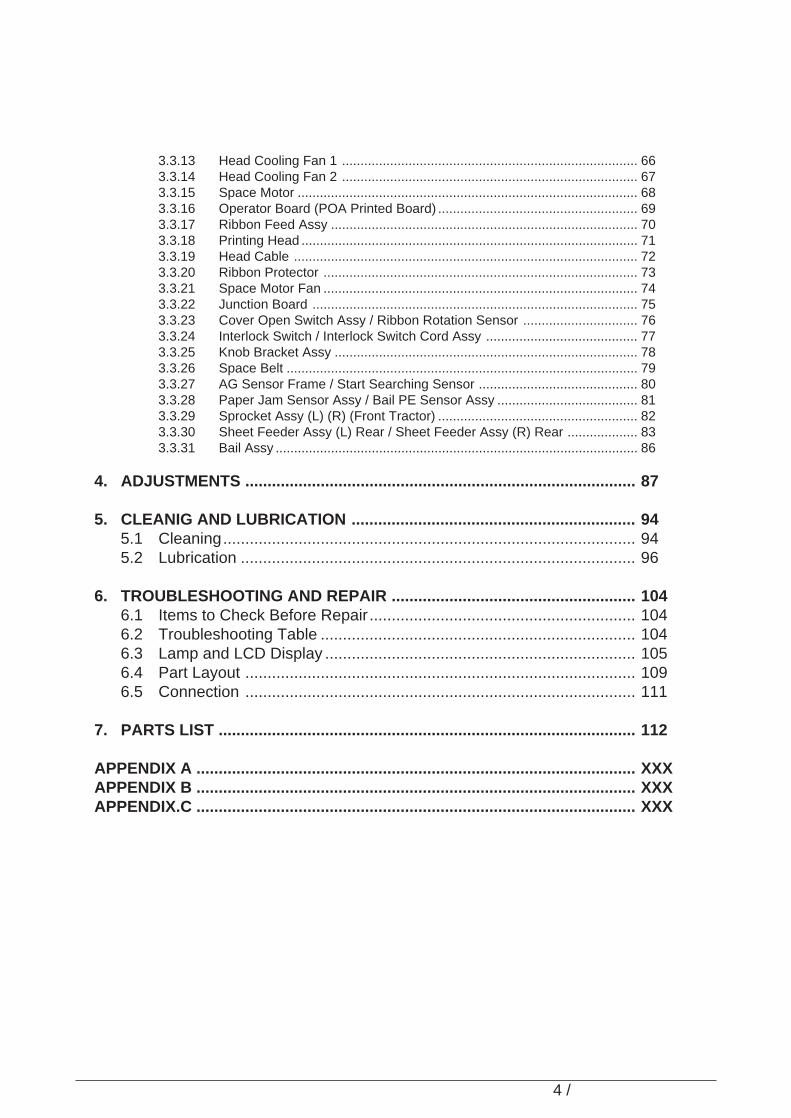
1.3 Option Specifications
Options available for the Pacemark 4410 are as follows.
(1) Interface boards(a) Okilan 6100e Network card
8
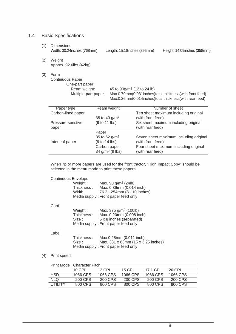
1.4 Basic Specifications
(1) DimensionsWidth: 30.24inches (768mm) Length: 15.16inches (395mm) Height: 14.09inches (358mm)
(2) WeightApprox. 92.6lbs (42kg)
(3) FormContinuous Paper
One-part paperReam weight: 45 to 90g/m2 (12 to 24 lb)Multiple-part paper Max.0.79mm(0.031inches)total thickness(with front feed)
Max.0.36mm(0.014inches)total thickness(with rear feed)
Paper type Ream weight Number of sheetCarbon-lined paper Ten sheet maximum including original
35 to 40 g/m2 (with front feed)Pressure-senstive (9 to 11 lbs) Six sheet maximum including originalpaper (with rear feed)
Paper35 to 52 g/m2 Seven sheet maximum including original
Interleaf paper (9 to 14 lbs) (with front feed)Carbon paper Four sheet maximum including original34 g/m2 (9 lbs) (with rear feed)
When 7p or more papers are used for the front tractor, "High Impact Copy" should beselected in the menu mode to print these papers.
Continuous EnvelopeWeight : Max. 90 g/m2 (24lb)Thickness : Max. 0.36mm (0.014 inch)Width : 76.2 - 254mm (3 - 10 inches)Media supply : Front paper feed only
CardWeight : Max. 375 g/m2 (100lb)Thickness : Max. 0.20mm (0.008 inch)Size : 5 x 8 inches (separated)Media supply : Front paper feed only
LabelThickness : Max 0.28mm (0.011 inch)Size : Max. 381 x 83mm (15 x 3.25 inches)Media supply : Front paper feed only
(4) Print speed
Print Mode Character Pitch10 CPI 12 CPI 15 CPI 17.1 CPI 20 CPI
HSD 1066 CPS 1066 CPS 1066 CPS 1066 CPS 1066 CPSNLQ 200 CPS 200 CPS 200 CPS 200 CPS 200 CPSUTILITY 800 CPS 800 CPS 800 CPS 800 CPS 800 CPS
9
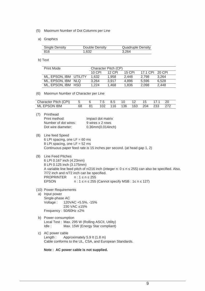
(5) Maximum Number of Dot Columns per Line
a) Graphics
Single Density Double Density Quadruple Density816 1,632 3,264
b) Text
Print Mode Character Pitch (CP)10 CPI 12 CPI 15 CPI 17.1 CPI 20 CPI
ML, EPSON, IBM UTILITY 1,632 1,958 2,448 2,798 3,264ML, EPSON, IBM NLQ 3,264 3,917 4,896 5,596 6,528ML, EPSON, IBM HSD 1,224 1,468 1,836 2,098 2,448
(6) Maximun Number of Character per Line
Character Pitch (CPI) 5 6 7.5 8.5 10 12 15 17.1 20ML EPSON IBM 68 81 102 116 136 163 204 233 272
(7) PrintheadPrint method: Impact dot matrixNumber of dot wires: 9 wires x 2 rowsDot wire diameter: 0.36mm(0.014inch)
(8) Line feed Speed6 LPI spacing, one LF = 60 ms8 LPI spacing, one LF = 52 msContinuous paper feed rate is 15 inches per second. (at head gap 1, 2)
(9) Line Feed Pitches6 LPI 0.167 inch (4.23mm)8 LPI 0.125 inch (3.175mm)A variable line feed pitch of n/216 inch (integer n: 0 ≤ n ≤ 255) can also be specified. Also,7/72 inch and n/72 inch can be specified.PROPRINTER n : 1 ≤ n ≤ 255EPSON n : 1 ≤ n ≤ 255 (Cannot specify MSB : 1≤ n ≤ 127)
(10) Power Requirementsa) Input power
Single-phase ACVoltage : 120VAC +5.5%, -15%
230 VAC ±15%Frequency : 50/60Hz ±2%
b) Power consumptionLocal Test : Max. 295 W (Rolling ASCII, Utility)Idle : Max. 15W (Energy Star compliant)
c) AC power cableLength : Approximately 5.9 It (1.8 m)Cable conforms to the UL, CSA, and European Standards.
Note : AC power cable is not supplied.
10
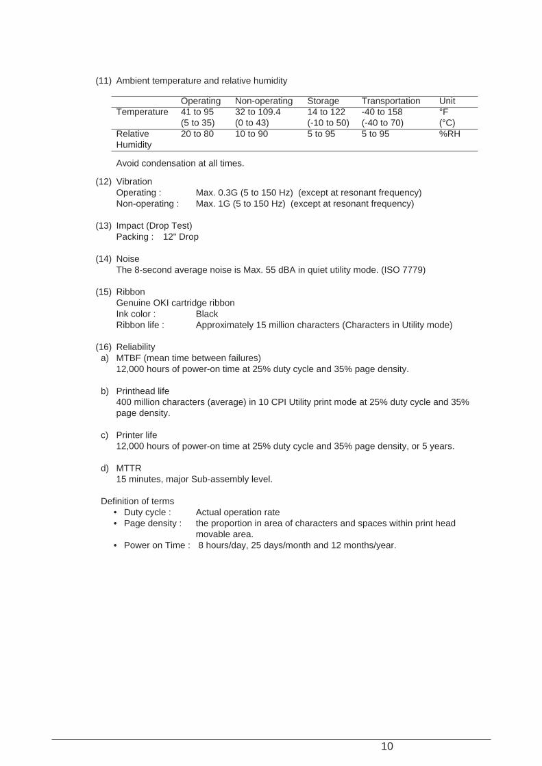
(11) Ambient temperature and relative humidity
Operating Non-operating Storage Transportation UnitTemperature 41 to 95 32 to 109.4 14 to 122 -40 to 158 °F
(5 to 35) (0 to 43) (-10 to 50) (-40 to 70) (°C)Relative 20 to 80 10 to 90 5 to 95 5 to 95 %RHHumidity
Avoid condensation at all times.
(12) VibrationOperating : Max. 0.3G (5 to 150 Hz) (except at resonant frequency)Non-operating : Max. 1G (5 to 150 Hz) (except at resonant frequency)
(13) Impact (Drop Test)Packing : 12" Drop
(14) NoiseThe 8-second average noise is Max. 55 dBA in quiet utility mode. (ISO 7779)
(15) RibbonGenuine OKI cartridge ribbonInk color : BlackRibbon life : Approximately 15 million characters (Characters in Utility mode)
(16) Reliabilitya) MTBF (mean time between failures)
12,000 hours of power-on time at 25% duty cycle and 35% page density.
b) Printhead life400 million characters (average) in 10 CPI Utility print mode at 25% duty cycle and 35%page density.
c) Printer life12,000 hours of power-on time at 25% duty cycle and 35% page density, or 5 years.
d) MTTR15 minutes, major Sub-assembly level.
Definition of terms• Duty cycle : Actual operation rate• Page density : the proportion in area of characters and spaces within print head
movable area.• Power on Time : 8 hours/day, 25 days/month and 12 months/year.

11
2. THEORY OF OPERATION
2.1 Electrical OperationThe electrical operation of the printer circuit is described in this section.
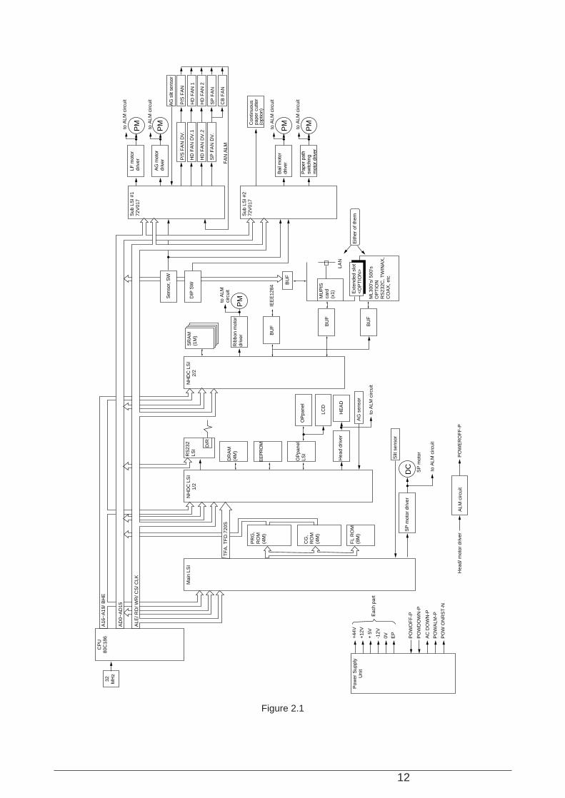
2.1.1 SummaryFig. 2-1 shows the block diagram of the printer.The control board is made up of the microprocessors, peripheral circuits, drive circuits, sensors andinterface connectors.The power to the control board is supplied by the power board through the connector cord.The power to other electrical parts is also distributed through the connectors within the control board.
2.1.2 Microprocessor and the peripheral circuit
(1) Microprocessor (IC24: 80C186-16)This processor is a CMOS single-chip computer with integrated peripheral device functionsand a 16 bit MPU core.The processor has a 20 bit address bus and a 16 bit data bus.It is capable of accessing up to 4M bit program memory and 4M bit of data memory.The following characteristics are also provided:• High-Speed DMA Channel x 2• Programmable Interrupt Controller• Programmable 16-bit Timer x 3• Programmable Memory and Peripheral Chip-Select Logic• Programmable Wait State Generator• Local Bus ControllerAnd others.The function of this microprocessor is to provide a central mechanism for the entire printerby executing the control program through the LSI and driver circuits.
12
Figure 2.1
to A
LM c
ircui
t
LF m
otor
driv
erS
ub L
SI #
172
V01
7
Sub
LS
I #2
72V
017
AG
mot
ordr
iver
Sen
sor,
SW
DIP
SW
Bai
l mot
ordr
iver
Pap
er p
ath
switc
hing
m
otor
driv
er
to A
LM c
ircui
t
to A
LM
circ
uit
to A
LM c
ircui
t
to A
LM c
ircui
t
ALM
circ
uit
Hea
d/ m
otor
driv
erP
OW
ER
OF
F-P
SP
mot
or
SP
mot
or d
river
FL
RO
M(8
M)
+44
VP
ower
Sup
ply
Uni
t
CP
U80
C18
632 MH
z
+12
V
Eac
h pa
rt+
5V
-12V
0V EP
PO
WO
FF
-P
PO
WD
OW
N-P
AC
DO
WN
-P
PO
W O
NR
ST
-N
PO
WA
LM-P
CG
,R
OM
(4M
)
PR
G,
RO
M(4
M)
Slit
sen
sor
IEE
E12
84
BU
F
BU
F
BU
F
OP
pane
lO
Ppa
nel
LSI
DR
AM
(4M
)
RS
232
LSI
D/R
EE
PR
OM
LCD
HE
AD
Hea
d dr
iver
AG
sen
sor
Rib
bon
mot
ordr
iver
SR
AM
(1M
)N
HD
C L
SI
2/2
NH
DC
LS
I1/
2M
ain
LSI
BU
F
MU
PIS
ca
rd(x
1) Ext
ende
d sl
ot<
OP
TIO
N>
LAN
ML3
00's
/ 500
'sO
PT
ION
RS
232C
, TW
INA
X,
CO
AX
, etc
to A
LM c
ircui
t
to A
LM c
ircui
t
AG
slit
sen
sor
P/S
FA
NP
/S F
AN
DV
.
HD
FA
N D
V.1
HD
FA
N D
V.2
SP
FA
N D
V.
FA
N A
LM
HD
FA
N 1
HD
FA
N 2
SP
FA
N
CB
FA
N
Con
tinuo
us
pape
r cu
tter
(opt
ion)
Eith
er o
f the
m
PM
PM
PM
DC
PM
PM
TF
A. T
FD
.720
S
ALE
/ RD
/ WR
/ CS
/ CLK
AD
0~A
D15
A16
~A
19/ B
HE
13
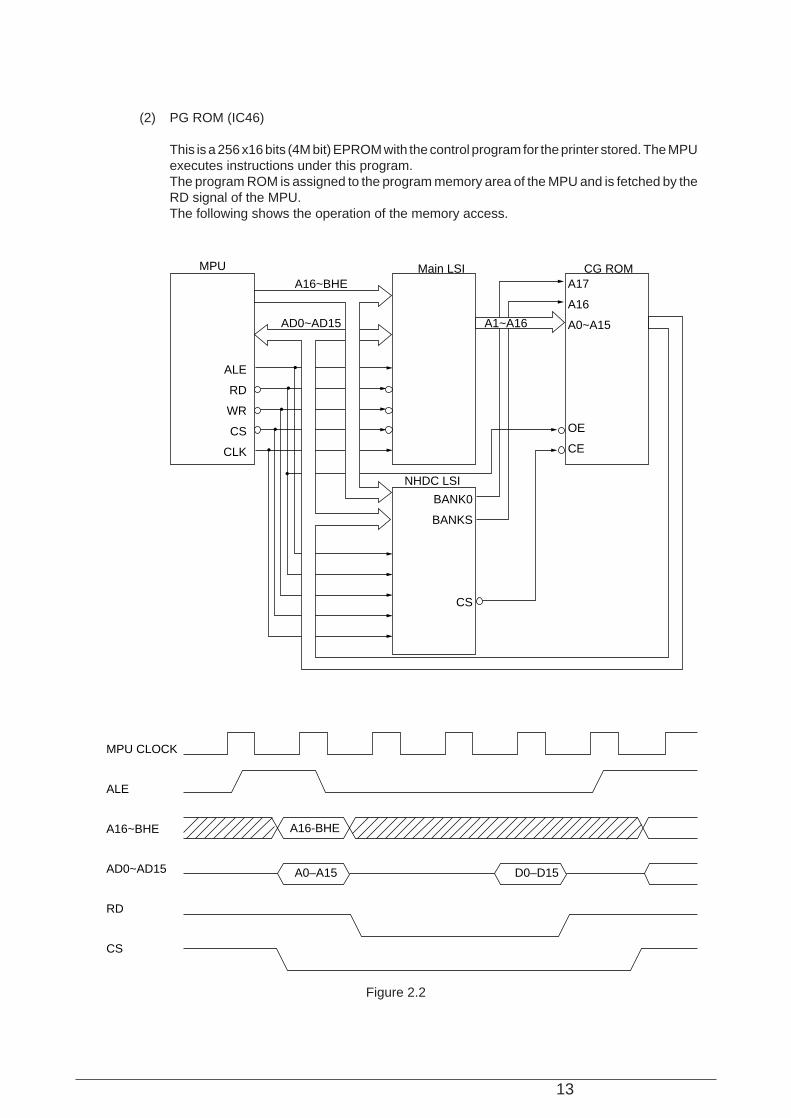
(2) PG ROM (IC46)
This is a 256 x16 bits (4M bit) EPROM with the control program for the printer stored. The MPUexecutes instructions under this program.The program ROM is assigned to the program memory area of the MPU and is fetched by theRD signal of the MPU.The following shows the operation of the memory access.
Figure 2.2
MPU CLOCK
ALE
A16~BHE
AD0~AD15
RD
CS
AD0~AD15
A16~BHE
MPU Main LSI CG ROM
NHDC LSI
A16-BHE
A0–A15 D0–D15
ALE
RD
WR
CS
CLK
BANK0
BANKS
CS
A17
A16
A0~A15
OE
CE
A1~A16
14
Figure 2.3
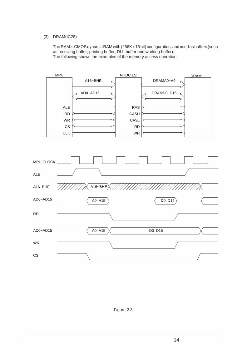
(3) DRAM(IC28)
The RAM is CMOS dynamic RAM with (256K x 16 bit) configuration, and used as buffers (suchas receiving buffer, printing buffer, DLL buffer and working buffer).The following shows the examples of the memory access operation.
MPU CLOCK
ALE
A16~BHE
AD0~AD15
RD
AD0~AD15
WR
CS
AD0~AD15
A16~BHE
DRAMD0~D15
DRAMA0~A9
MPU NHDC LSI DRAM
A16~BHE
A0–A15 D0–D15
A0–A15 D0–D15
ALE
RD
WR
CS
CLK
RAS
CASU
CASL
RD
WR
15
Figure 2.4
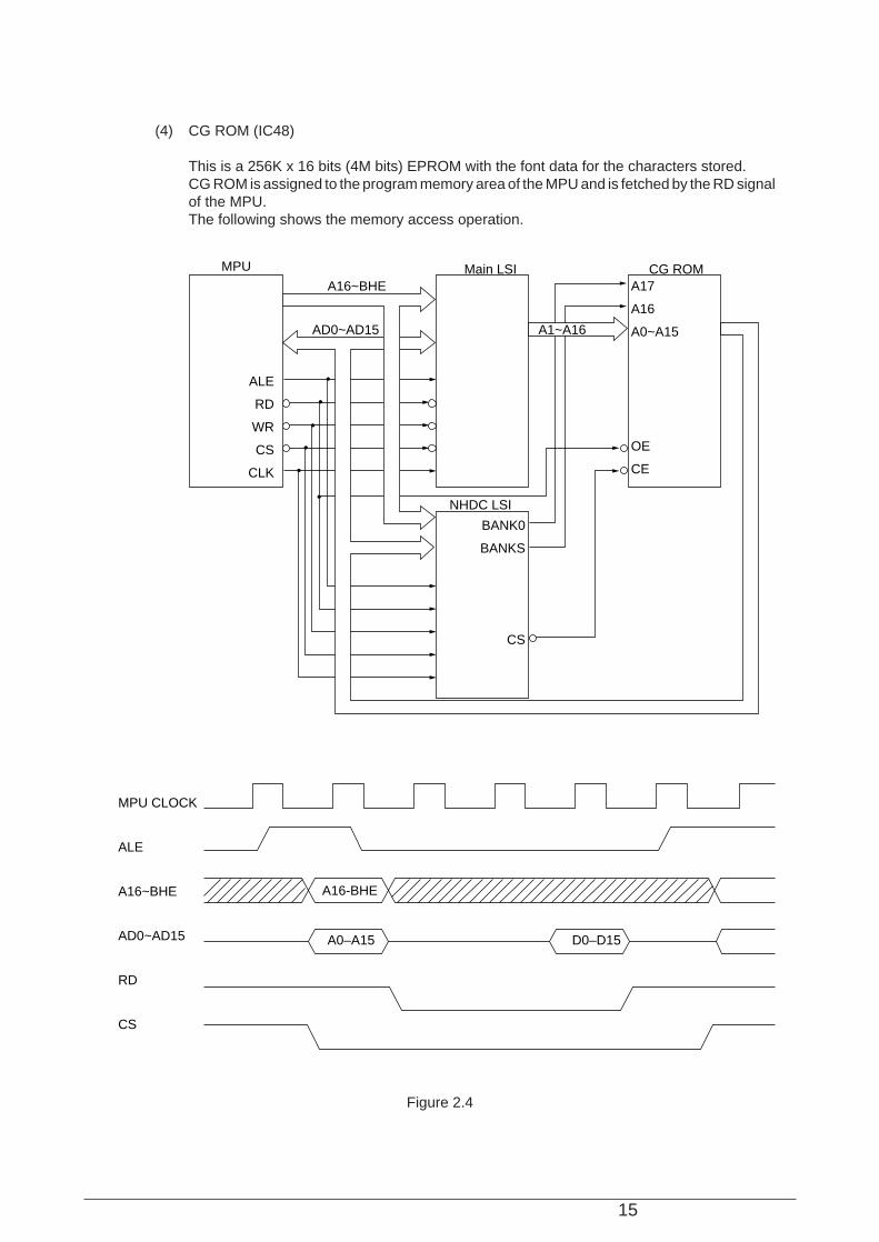
(4) CG ROM (IC48)
This is a 256K x 16 bits (4M bits) EPROM with the font data for the characters stored.CG ROM is assigned to the program memory area of the MPU and is fetched by the RD signalof the MPU.The following shows the memory access operation.
MPU CLOCK
ALE
A16~BHE
AD0~AD15
RD
CS
AD0~AD15
A16~BHE
MPU Main LSI CG ROM
NHDC LSI
A16-BHE
A0–A15 D0–D15
ALE
RD
WR
CS
CLK
BANK0
BANKS
CS
A17
A16
A0~A15
OE
CE
A1~A16
16
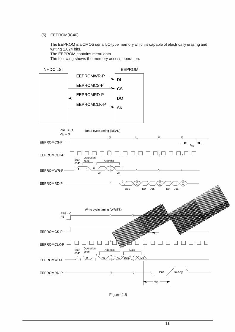
(5) EEPROM(IC40)
The EEPROM is a CMOS serial I/O type memory which is capable of electrically erasing andwriting 1,024 bits.The EEPROM contains menu data.The following shows the memory access operation.
Figure 2.5
NHDC LSI EEPROM
EEPROMWR-P
EEPROMCS-P
EEPROMRD-P
EEPROMCLK-P
DI
CS
DO
SK
ReadyBus
twp
D0D15A0A511
0
Startcode
Operationcode
Address Data
tCS
PRE = OPE
AddressStartcode
Operationcode
EEPROMRD-P
EEPROMWR-P
EEPROMCLK-P
EEPROMCS-P
EEPROMRD-P
EEPROMWR-P
EEPROMCLK-P
EEPROMCS-P
D15 D0 D15 D0 D15
0
A0A5
011
tCS
PRE = OPE = X
Read cycle timing (READ)
Write cycle timing (WRITE)
17
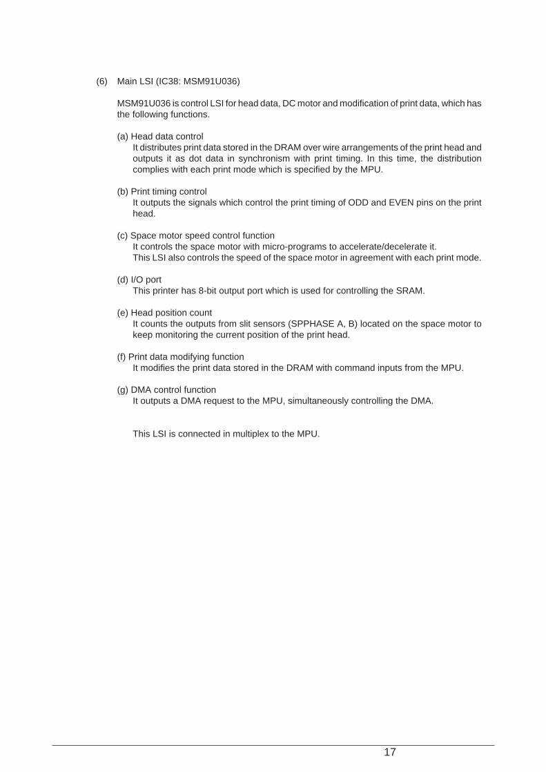
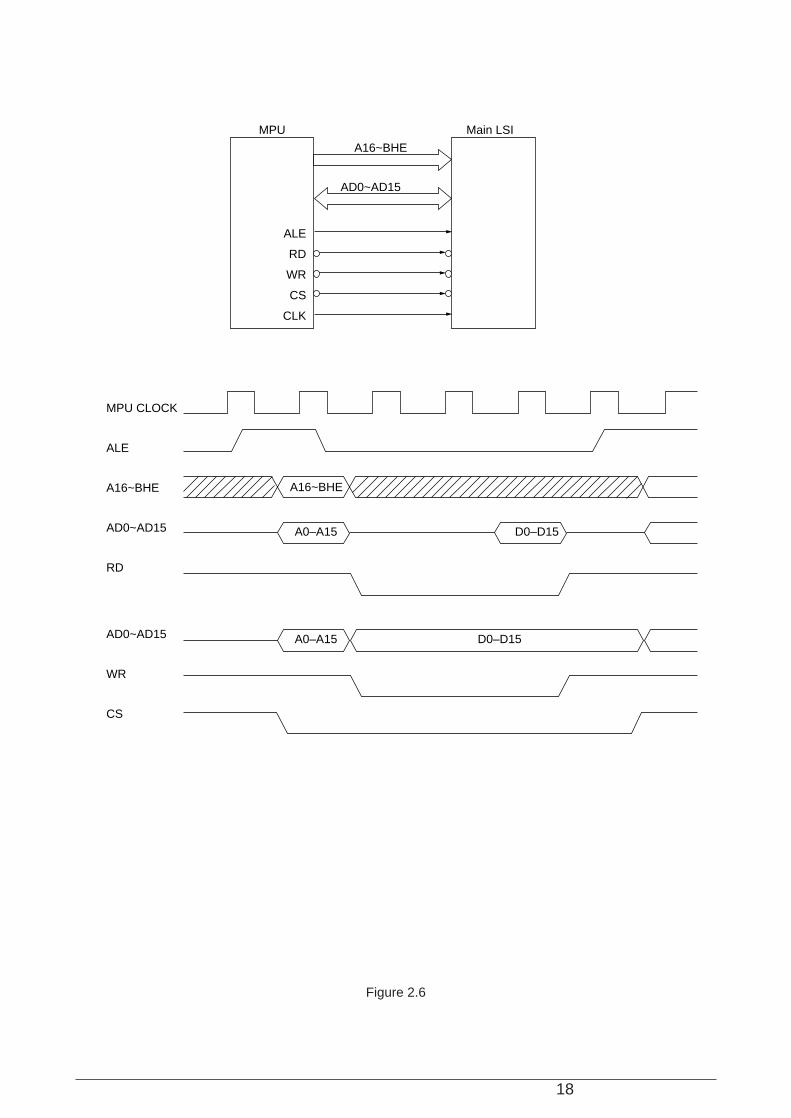
(6) Main LSI (IC38: MSM91U036)
MSM91U036 is control LSI for head data, DC motor and modification of print data, which hasthe following functions.
(a) Head data controlIt distributes print data stored in the DRAM over wire arrangements of the print head andoutputs it as dot data in synchronism with print timing. In this time, the distributioncomplies with each print mode which is specified by the MPU.
(b) Print timing controlIt outputs the signals which control the print timing of ODD and EVEN pins on the printhead.
(c) Space motor speed control functionIt controls the space motor with micro-programs to accelerate/decelerate it.This LSI also controls the speed of the space motor in agreement with each print mode.
(d) I/O portThis printer has 8-bit output port which is used for controlling the SRAM.
(e) Head position countIt counts the outputs from slit sensors (SPPHASE A, B) located on the space motor tokeep monitoring the current position of the print head.
(f) Print data modifying functionIt modifies the print data stored in the DRAM with command inputs from the MPU.
(g) DMA control functionIt outputs a DMA request to the MPU, simultaneously controlling the DMA.
This LSI is connected in multiplex to the MPU.
18
Figure 2.6
MPU CLOCK
ALE
A16~BHE
AD0~AD15
RD
AD0~AD15
WR
CS
AD0~AD15
A16~BHE
MPU Main LSI
A16~BHE
A0–A15 D0–D15
A0–A15 D0–D15
ALE
RD
WR
CS
CLK
19
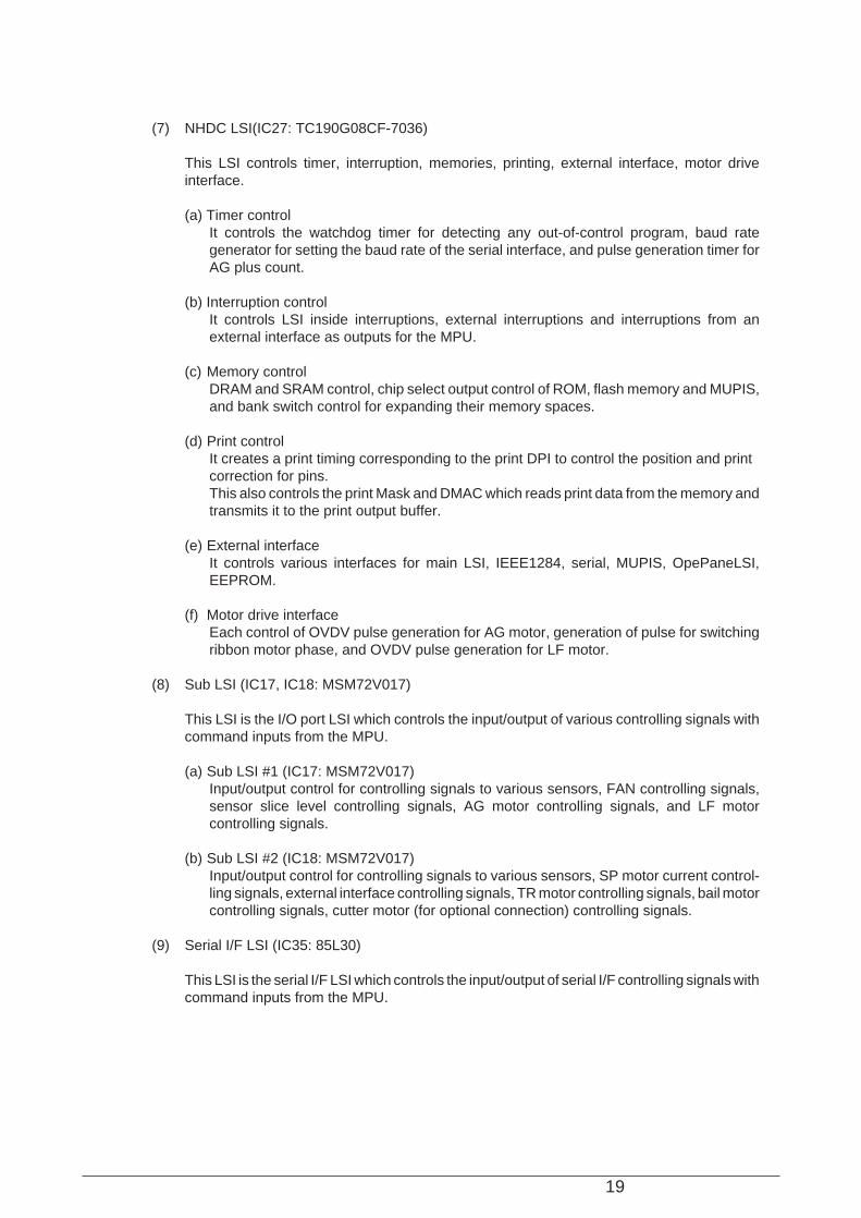
(7) NHDC LSI(IC27: TC190G08CF-7036)
This LSI controls timer, interruption, memories, printing, external interface, motor driveinterface.
(a) Timer controlIt controls the watchdog timer for detecting any out-of-control program, baud rategenerator for setting the baud rate of the serial interface, and pulse generation timer forAG plus count.
(b) Interruption controlIt controls LSI inside interruptions, external interruptions and interruptions from anexternal interface as outputs for the MPU.
(c) Memory controlDRAM and SRAM control, chip select output control of ROM, flash memory and MUPIS,and bank switch control for expanding their memory spaces.
(d) Print controlIt creates a print timing corresponding to the print DPI to control the position and printcorrection for pins.This also controls the print Mask and DMAC which reads print data from the memory andtransmits it to the print output buffer.
(e) External interfaceIt controls various interfaces for main LSI, IEEE1284, serial, MUPIS, OpePaneLSI,EEPROM.
(f) Motor drive interfaceEach control of OVDV pulse generation for AG motor, generation of pulse for switchingribbon motor phase, and OVDV pulse generation for LF motor.
(8) Sub LSI (IC17, IC18: MSM72V017)
This LSI is the I/O port LSI which controls the input/output of various controlling signals withcommand inputs from the MPU.
(a) Sub LSI #1 (IC17: MSM72V017)Input/output control for controlling signals to various sensors, FAN controlling signals,sensor slice level controlling signals, AG motor controlling signals, and LF motorcontrolling signals.
(b) Sub LSI #2 (IC18: MSM72V017)Input/output control for controlling signals to various sensors, SP motor current control-ling signals, external interface controlling signals, TR motor controlling signals, bail motorcontrolling signals, cutter motor (for optional connection) controlling signals.
(9) Serial I/F LSI (IC35: 85L30)
This LSI is the serial I/F LSI which controls the input/output of serial I/F controlling signals withcommand inputs from the MPU.
20
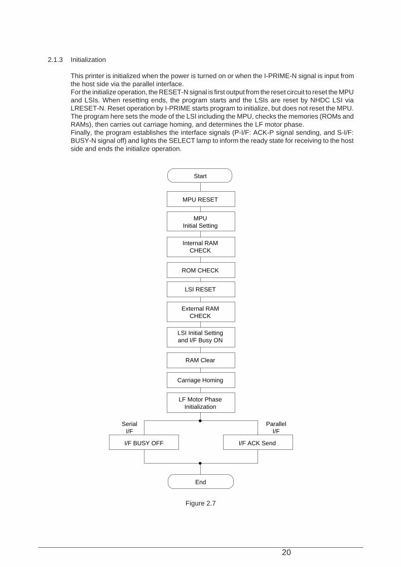
2.1.3 Initialization
This printer is initialized when the power is turned on or when the I-PRIME-N signal is input fromthe host side via the parallel interface.For the initialize operation, the RESET-N signal is first output from the reset circuit to reset the MPUand LSIs. When resetting ends, the program starts and the LSIs are reset by NHDC LSI viaLRESET-N. Reset operation by I-PRIME starts program to initialize, but does not reset the MPU.The program here sets the mode of the LSI including the MPU, checks the memories (ROMs andRAMs), then carries out carriage homing, and determines the LF motor phase.Finally, the program establishes the interface signals (P-I/F: ACK-P signal sending, and S-I/F:BUSY-N signal off) and lights the SELECT lamp to inform the ready state for receiving to the hostside and ends the initialize operation.
Figure 2.7
End
I/F BUSY OFF
SerialI/F
I/F ACK Send
ParallelI/F
LF Motor PhaseInitialization
Carriage Homing
RAM Clear
LSI Initial Settingand I/F Busy ON
External RAMCHECK
LSI RESET
ROM CHECK
Internal RAMCHECK
MPUInitial Setting
MPU RESET
Start

21
2.1.4 Interface control
The PM4410 is provided with the centronics parallel interface and RS-232C serial interface asstandard features.Also, it can be connected to the optional Network I/F Card. The interface cablecan be connected simultaneously with these interfaces.These interfaces can be switched with the menu switch on the operation panel, in addition, you candesignate auto-select for them. The MPU communicates with hosts through the NHDC accordingto the selected interface mode. The selected interface is stored to the EEPROM and can maintaineven after powering the printer off.
2.1.5 Parallel Interface Control
The Parallel data input from the host to the NHDC LSI is latched to its internal register at the fallingor rising edge of the STROBE-N signal.At the same time, the LSI sets the BUSY signal to the high level to inform the host that the datais being processed, and outputs the INT-P signal to inform the MPU of data reception. The datais read upon receiving the RD-N signal from the MPU.When the data processing ends, the BUSY signal is set to off and the ACK-N signal in sent torequest the next data. When reception is impossible because the buffer is full, the BUSY signal issent to request stopping of data transmission.
Figure 2.8
A/D bus
MPU NHDC LSI
Linedriver receiver
BSYP
ACKN
PSBNINT-P
INT INT
Parallel I/F
BUSY
ACK-N
STB-N
Data1 to 8
STROBE
BUSY
ACK
INT
2~8µs
500ns max.
or or
22
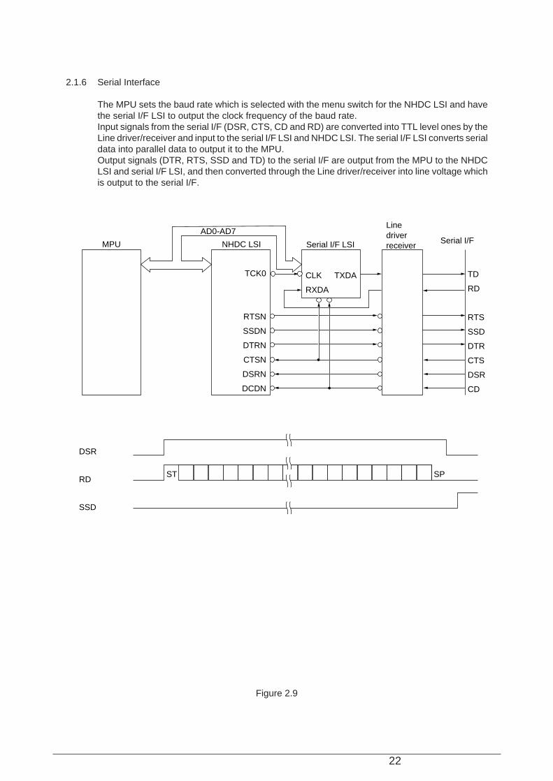
2.1.6 Serial Interface
The MPU sets the baud rate which is selected with the menu switch for the NHDC LSI and havethe serial I/F LSI to output the clock frequency of the baud rate.Input signals from the serial I/F (DSR, CTS, CD and RD) are converted into TTL level ones by theLine driver/receiver and input to the serial I/F LSI and NHDC LSI. The serial I/F LSI converts serialdata into parallel data to output it to the MPU.Output signals (DTR, RTS, SSD and TD) to the serial I/F are output from the MPU to the NHDCLSI and serial I/F LSI, and then converted through the Line driver/receiver into line voltage whichis output to the serial I/F.
Figure 2.9
DSR
RD
SSD
MPU NHDC LSI Serial I/F LSI Serial I/F
Linedriverreceiver
RTSN
SSDN
DTRN
CTSN
DSRN
DCDN
TCK0 CLK
RXDA
TXDA TD
RD
RTS
SSD
DTR
CTS
DSR
CD
ST SP
AD0-AD7
23
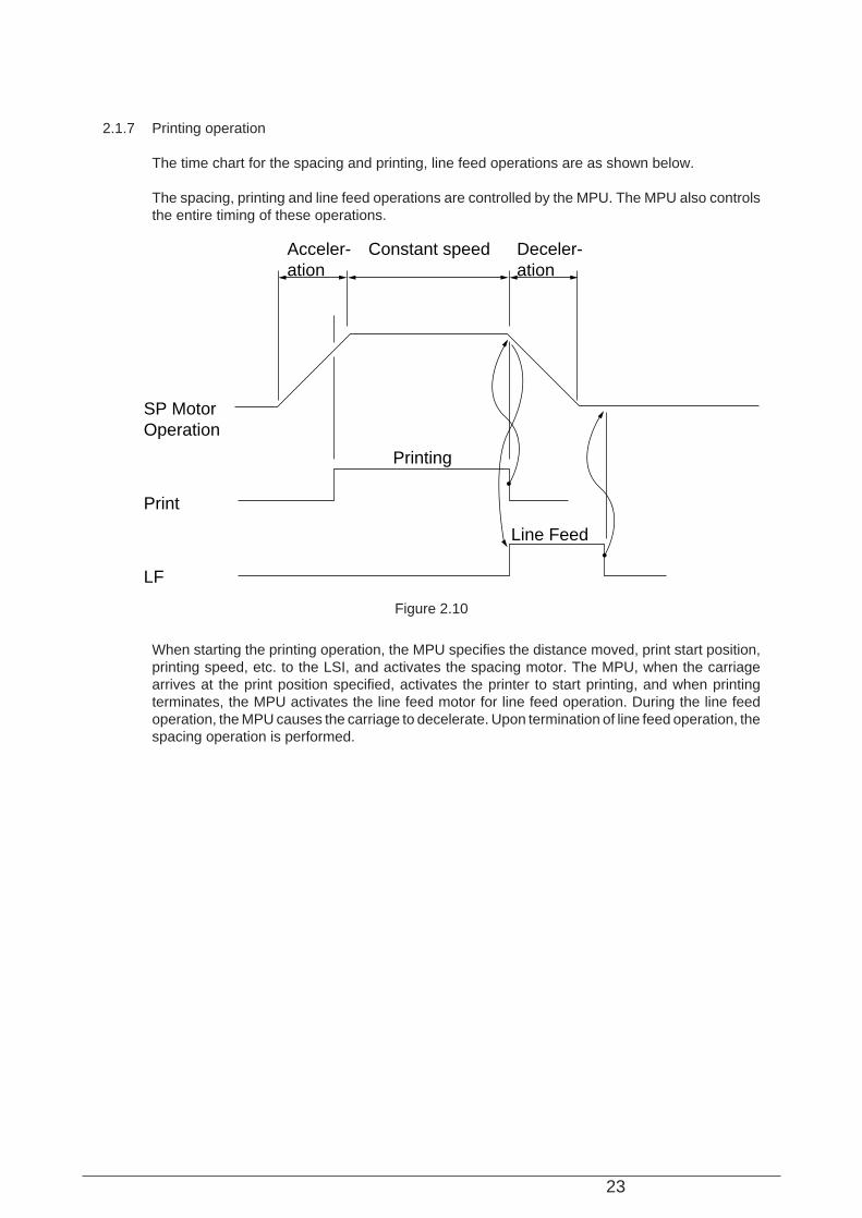
2.1.7 Printing operation
The time chart for the spacing and printing, line feed operations are as shown below.
The spacing, printing and line feed operations are controlled by the MPU. The MPU also controlsthe entire timing of these operations.
When starting the printing operation, the MPU specifies the distance moved, print start position,printing speed, etc. to the LSI, and activates the spacing motor. The MPU, when the carriagearrives at the print position specified, activates the printer to start printing, and when printingterminates, the MPU activates the line feed motor for line feed operation. During the line feedoperation, the MPU causes the carriage to decelerate. Upon termination of line feed operation, thespacing operation is performed.
Figure 2.10
SP MotorOperation
Printing
Acceler-ation
Deceler-ation
Constant speed
Line Feed
LF
24
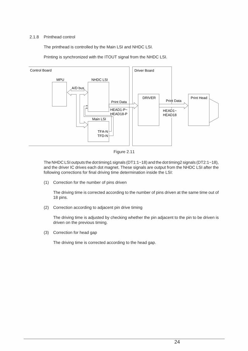
2.1.8 Printhead control
The printhead is controlled by the Main LSI and NHDC LSI.
Printing is synchronized with the ITOUT signal from the NHDC LSI.
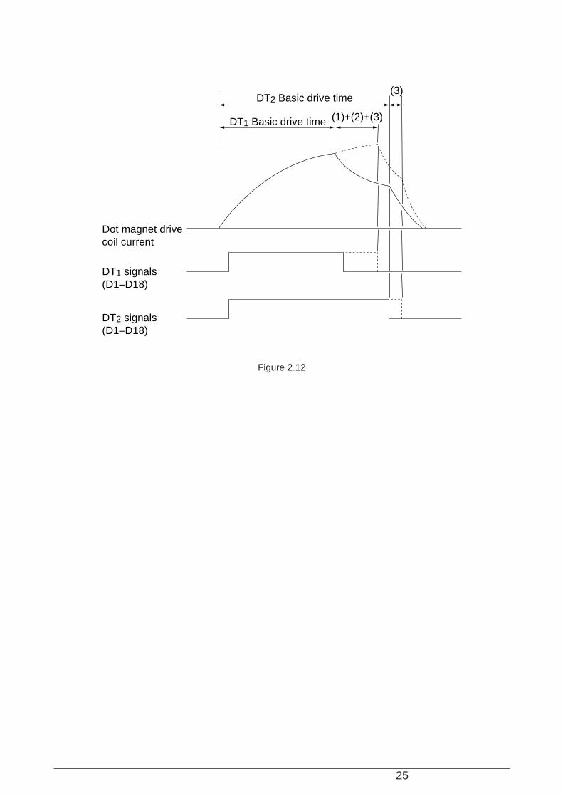
The NHDC LSI outputs the dot timing1 signals (DT1:1~18) and the dot timing2 signals (DT2:1~18),and the driver IC drives each dot magnet. These signals are output from the NHDC LSI after thefollowing corrections for final driving time determination inside the LSI:
(1) Correction for the number of pins driven
The driving time is corrected according to the number of pins driven at the same time out of18 pins.
(2) Correction according to adjacent pin drive timing
The driving time is adjusted by checking whether the pin adjacent to the pin to be driven isdriven on the previous timing.
(3) Correction for head gap
The driving time is corrected according to the head gap.
Figure 2.11
Print Data
MPU NHDC LSI
Main LSI
DRIVER
HEAD1-P~HEAD18-P
Print DataPrint Head
Control Board
A/D bus
HEAD1~HEAD18
Driver Board
TFA-NTFD-N
25
Figure 2.12
Dot magnet drivecoil current
DT1 signals(D1–D18)
DT2 signals(D1–D18)
DT2 Basic drive time
(1)+(2)+(3)DT1 Basic drive time
(3)
26
2.1.9 Print Compensation Control
The print compensation can be made as shown below:
(a) Simultaneous Compensation of the number of impact pinsThe NHDC LSI is provided with the compensation table for each pin to make necessarycompensation.
Number of impact pins Few Many
Drive time Short Long
(b) Duty control1. If the number of the lines which exceeds 60% printing duty is continuous 8 lines, the printer
starts 2-path printing at the 8th line.2. If the printer can activate 12 pins simultaneously in a line, it 2-path prints the line.
(c) Temperature compensation (See2.1.14 "Alarm Circuit.")
(d) Print mode compensationAccording to the thickness of the printing medium, the print mode is compensated as shownin the table below:
Head Gap Range 1 2 3 4 5
Print speed 100% 97% 95% 90% 89%
Drive time Short Long
(Drive time lengthens at each step.)
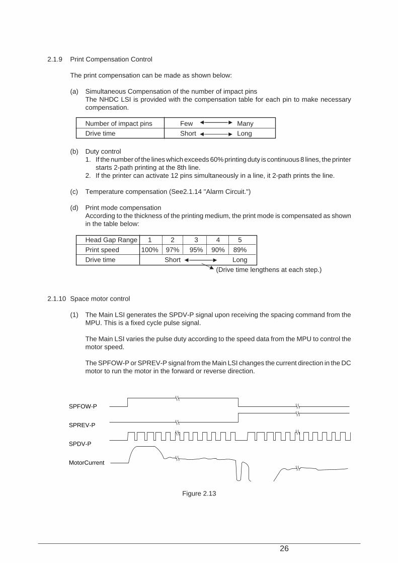
2.1.10 Space motor control
(1) The Main LSI generates the SPDV-P signal upon receiving the spacing command from theMPU. This is a fixed cycle pulse signal.
The Main LSI varies the pulse duty according to the speed data from the MPU to control themotor speed.
The SPFOW-P or SPREV-P signal from the Main LSI changes the current direction in the DCmotor to run the motor in the forward or reverse direction.
SPFOW-P
SPREV-P
SPDV-P
MotorCurrent
Figure 2.13
27
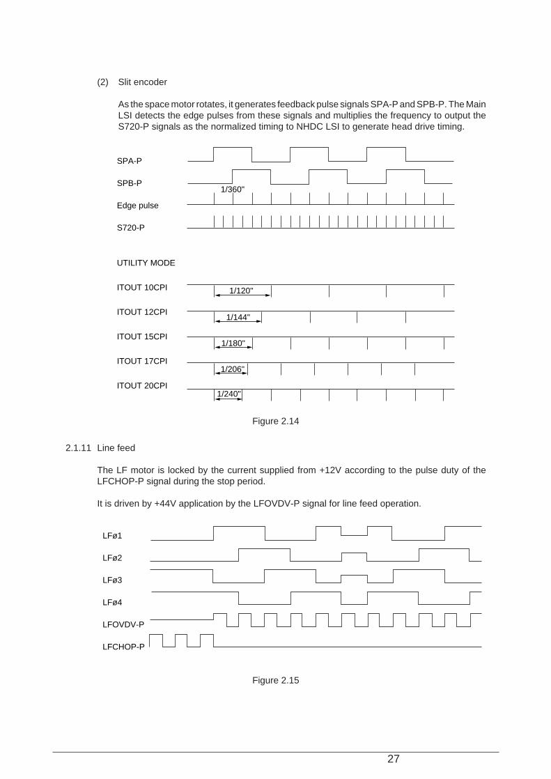
(2) Slit encoder
As the space motor rotates, it generates feedback pulse signals SPA-P and SPB-P. The MainLSI detects the edge pulses from these signals and multiplies the frequency to output theS720-P signals as the normalized timing to NHDC LSI to generate head drive timing.
2.1.11 Line feed
The LF motor is locked by the current supplied from +12V according to the pulse duty of theLFCHOP-P signal during the stop period.
It is driven by +44V application by the LFOVDV-P signal for line feed operation.
SPA-P
SPB-P
Edge pulse
S720-P
UTILITY MODE
ITOUT 10CPI
ITOUT 12CPI
ITOUT 15CPI
ITOUT 17CPI
ITOUT 20CPI
1/360"
1/120"
1/144"
1/180"
1/206"
1/240"
LFø1
LFø2
LFø3
LFø4
LFOVDV-P
LFCHOP-P
Figure 2.14
Figure 2.15
28
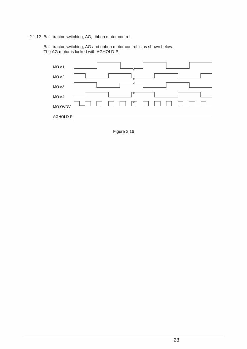
2.1.12 Bail, tractor switching, AG, ribbon motor control
Bail, tractor switching, AG and ribbon motor control is as shown below.The AG motor is locked with AGHOLD-P.
MO ø1
MO ø2
MO ø3
MO ø4
MO OVDV
AGHOLD-P
Figure 2.16
29
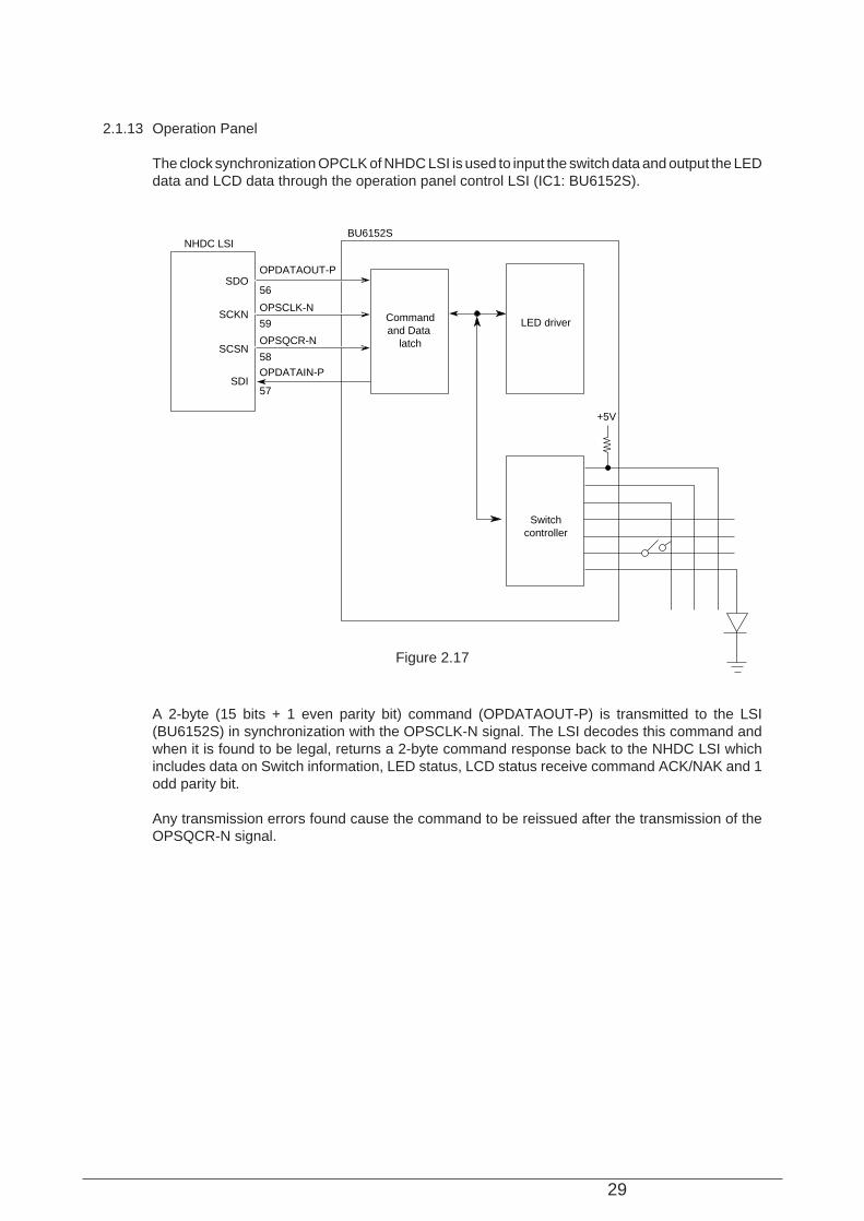
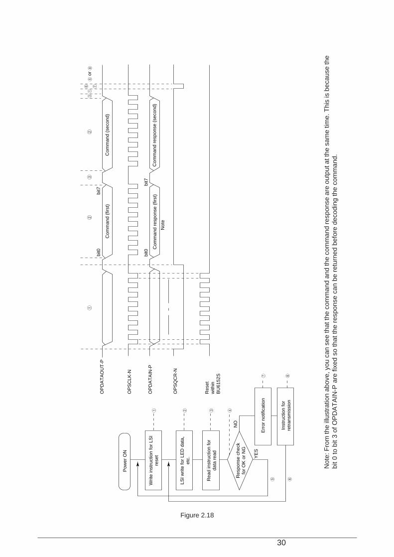
2.1.13 Operation Panel
The clock synchronization OPCLK of NHDC LSI is used to input the switch data and output the LEDdata and LCD data through the operation panel control LSI (IC1: BU6152S).
A 2-byte (15 bits + 1 even parity bit) command (OPDATAOUT-P) is transmitted to the LSI(BU6152S) in synchronization with the OPSCLK-N signal. The LSI decodes this command andwhen it is found to be legal, returns a 2-byte command response back to the NHDC LSI whichincludes data on Switch information, LED status, LCD status receive command ACK/NAK and 1odd parity bit.
Any transmission errors found cause the command to be reissued after the transmission of theOPSQCR-N signal.
NHDC LSIBU6152S
OPDATAOUT-P
OPSCLK-N
OPSQCR-N
OPDATAIN-P
56
59
58
SDO
SCKN
SCSN
SDI
Commandand Data
latch
LED driver
Switchcontroller
+5V
57
Figure 2.17
30
Not
e: F
rom
the
illus
trat
ion
abov
e, y
ou c
an s
ee th
at th
e co
mm
and
and
the
com
man
d re
spon
se a
re o
utpu
t at t
he s
ame
time.
Thi
s is
bec
ause
the
bit 0
to b
it 3
of O
PD
AT
AIN
-P a
re fi
xed
so th
at th
e re
spon
se c
an b
e re
turn
ed b
efor
e de
codi
ng th
e co
mm
and.
OP
DA
TA
OU
T-P
OP
SC
LK-N
OP
DA
TA
IN-P
OP
SQ
CR
-N
12
32
316 75
or 8
bit0
bit7
Com
man
d (f
irst)
Com
man
d (s
econ
d)
Com
man
d re
spon
se (
first
)C
omm
and
resp
onse
(se
cond
)
Not
e
bit0
bit7
Res
etw
ithin
BU
6152
S
Pow
er O
N
Writ
e in
stru
ctio
n fo
r LS
Ire
set
LSI w
rite
for
LED
dat
a,et
c.
Rea
d in
stru
ctio
n fo
rda
ta r
ead
Res
pons
e ch
eck
for
OK
or
NG
Err
or n
otifi
catio
n
Inst
ruct
ion
for
retr
ansm
issi
on
1 2 3 4
7 8
5 6
NO
YE
S
Figure 2.18
31
2.1.14 Alarm circuits
(1) Driver circuit abnormality detection alarm.
This protective circuit prevents secondary troubles by stopping the power supply upondetection of an abnormality in the print head, SP motor driver circuit or other motor drivercircuits.
This circuit monitors the driving time by means of the signals (DT1COM1, SPV, LF COM, AG-MCOM, RBN-MCOM, TR-MCOM, BEIL-MCOM and RENCOM) connected to the overdrivesignals for each driver circuit. If any driver circuit driving time exceeds the specified time, thePOWOFF-P signal is output to switch off the power supply to stop all DC voltage outputs.
(2) Head high temperature alarm circuit
The thermistor built in the head monitors the head temperature for head coil protection.
If high duty printing continues for a long time, the head temperature rises. If it reaches acertain level (approx. 148 °C and 158°C), head high temperature alarm 1 is detected to startone-way printing with a 40 ms interval after each line. When head temperature alarm 2 isdetected to start one-way and two-pass printing with a 1.2 sec. interval after each line for thehead temperature to fall. When the temperature falls to below the detection temperature,normal printing operation restarts.
As the head temperature rises, the resistance of the thermistor decreases and the potentialof the input to the comparator in the head thermistor alarm circuit rises, when the potentialgoes above the alarm 1 specific level, MPU goes into alarm 1 procedure, simultaneously MPUcontinues to check if the potential goes above alarm 2 specific level. When going below alarm2 level, MPU goes into alarm 2 procedure.
(3) Paper end detection circuit
Five sensors (front tractor paper end sensor, rear tractor paper end sensor, sheet jam sensor,sheet top sensor and sheet width sensor) are provided for different paper set routes to monitorpaper end. When paper runs out, the corresponding sensor is turned off to input theFTRPESW-P, RTRPESW-P, SHEETJAM-P, SHEETTOP-P, SHEETWITH-N signal to thesub LSI (IC17), and is read by the MPU. The MPU stops the printing operation, informs thehost of the paper end and jam, and lights the alarm lamp.
(4) Cover open alarm circuit
When the front access cover is PUSH opened, the COVEROPN1SW-P signal is input to themain LSI and the NHDC LSI from the cover open microswitch, and an invalid signal is inputto MPU. The MPU stops the printing operation as soon as possible, informs the host thatreceiving is impossible, and lights the alarm lamp.
When the front access cover is opened and, the interlock switch cuts the SP motor drivecurrent and makes the SP motor stop.
(5) Fan alarm circuit
For each of the five fans, the FANALM-P signal is provided to detect fan rotation/stop. Thesignal is at Low level when the fan rotates, while it becomes High when it stops. The MPUmonitors this signal level. When the High level is kept for one minute or longer, the MPU stopsthe printing operation, informs the host of the fan alarm, and lights the alarm lamp.
32
(6) Head thermistor short/open alarm circuit
The head thermistor voltage is monitored physically. When short or open circuit occurs, theHDTHALM-N signal is input to the sub LSI (IC18) and read by the MPU. The MPU stops theprinting operation, informs the host of the short/open alarm, and lights the alarm lamp.When the head is unloaded, the head thermistor becomes open, resulting in this alarm.
(7) SP motor thermal alarm circuit
The voltage at the thermistor, built in the SP motor encoder block, is monitored physically.When temperature higher than the specified level is detected, the SPTHACM-N signal is inputto the sub LSI (IC18) and read by the MPU. The MPU starts printing with an approx. 0.2 sec.interval after each line to cool down the printer.When the temperature becomes lower than the specified, normal printing will be resumed.
(8) Fuse alarm circuit
Fuses are mounted on each of the SP motor and the other pulse motors, including LF motor,where the voltage level is monitored physically. When one or both of the fuses on the maincontrol board are blown, the FUSEALM-P signal is input to the sub LSI (IC18) and read bythe MPU. The MPU stops the printing operation, informs the host of the fuse alarm, and lightsthe alarm lamp.
(9) Ribbon jam alarm circuit
The rotation detection knob mounted on the ribbon cassette synchronizes with ribbon rotationand detects the rotation using the sensor. The RBNSEN-P signal from this sensor is inputto the sub LSI (IC17) for the MPU to monitor the rotation. With no rotation for 16 sec. or longer,the MPU stops the printing operation, informs the host of the ribbon jam, and lights the alarmlamp.

33
2.1.15 Power supply circuit
This switching type power supply circuit supplies the +5 VDC, ±12 VDC and +44 VDC.
Rectification andsmoothing circuit
+44 V primaryswitching circuit
Noise filtercircuit
Alarm controlcircuit
Switchingcontrol circuit
AC input monitoringcircuit
Rectification andregulating circuit
+5 V and ±12 Vprimaty switchingcircuit
Rectification andsmoothing circuit
POWONRESTcircuit
+44V
POWALM-PPOWOFF-PPOWDWN-P
+5V
+12V-12V
POWONRST-N
ACDOWN-P
SW
ACIN
FUSE
The uses of output voltages and signals are described below.
Voltage/ signal Use
+5V Logic IC/ LED drive voltage
+12V Logic IC drive voltage, option interface line voltage and LF motor lockingvoltage
-12V Option interface line voltage
+44V Printhead, SP motor, LF motor, Other motors drive voltage
POW ALM-P Output from the power supply circuit upon detection of an abnormaltemperature rise in the power supply circuit or an overcurrent of +44V.
The control unit suppresses the overcurrent by two-pass printing. If theoutput does not change, the power supply circuit shuts off all DC output.
POW OFF-P Output from the main PCB upon detection of an abnormality in the print head,SP motor, LF motor, Other motor driver circuit, and shut all DC output off.
AC DOWN-P Output from the power supply circuit to the main PCB upon detection of noAC input with the AC switch turned off. Then the main PCB outputs thePOWOFF-P signal to the power supply circuit to have the necessaryinformation written into EEPROM.
POW DWN-P Output from the main PCB to the power supply circuit upon detection of nohost or operator access for approx. 10 min., to start the power-save mode.In this mode, the power supply circuit cuts off 44V output.
POW ONRST-N Output from the power supply reset circuit to the main PCB. On receiving thePOWONRST-N signal, the main PCB prepares the main PCB RESET-Nsignal and +5VDC.
Figure 2.19

40496501TH Draft Version 34
2.2 Mechanical Operation2.2.1 Printhead mechanism and operation (See Figure 2-13)
The printhead is a spring charged 18-pin (dual 9-pin) driving head using a permanent magnet. It is attached to the carriage, which moves in parallel with the platen. Electrically, this unit is connected to the control circuits through the control board.
Figure2-20 Arrangement of the head pinsView from the tip of the printhead
(1) The printhead configuration:The printhead is composed of the following parts:(a) Wire guide(b) Armature assembly (Wire, Armature, Spring, Yoke, Spacer)(c) Magnet assembly (Magnet, core, coil, Yoke)(d) Printed circuit board
(19/120 inches)
(3/120 inches)
(2/120 inches x4)(2/120 inches x4)
(1/7
2 in
ches
+0.
005)
(1/7
2 in
ches
+0.
005)
x 8
(2/120 inches)(2/120 inches)
#18 #17
#2 #1
35
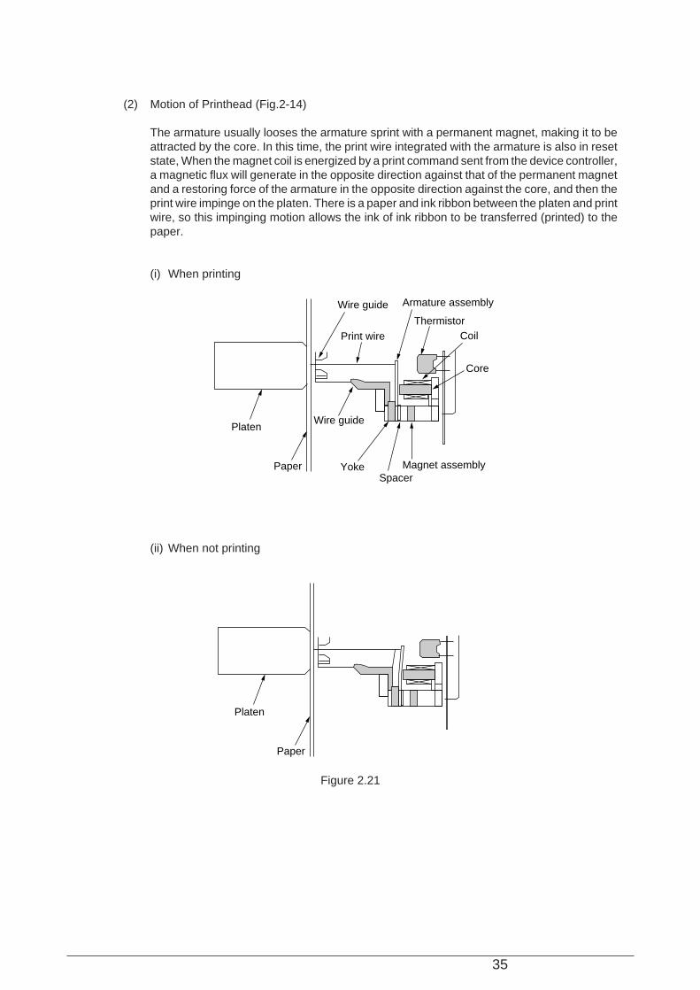
(2) Motion of Printhead (Fig.2-14)
The armature usually looses the armature sprint with a permanent magnet, making it to beattracted by the core. In this time, the print wire integrated with the armature is also in resetstate, When the magnet coil is energized by a print command sent from the device controller,a magnetic flux will generate in the opposite direction against that of the permanent magnetand a restoring force of the armature in the opposite direction against the core, and then theprint wire impinge on the platen. There is a paper and ink ribbon between the platen and printwire, so this impinging motion allows the ink of ink ribbon to be transferred (printed) to thepaper.
(i) When printing
(ii) When not printing
Wire guide Armature assembly
ThermistorCoil
Core
Magnet assemblySpacer
Yoke
Print wire
Wire guidePlaten
Paper
Platen
Paper
Figure 2.21
36
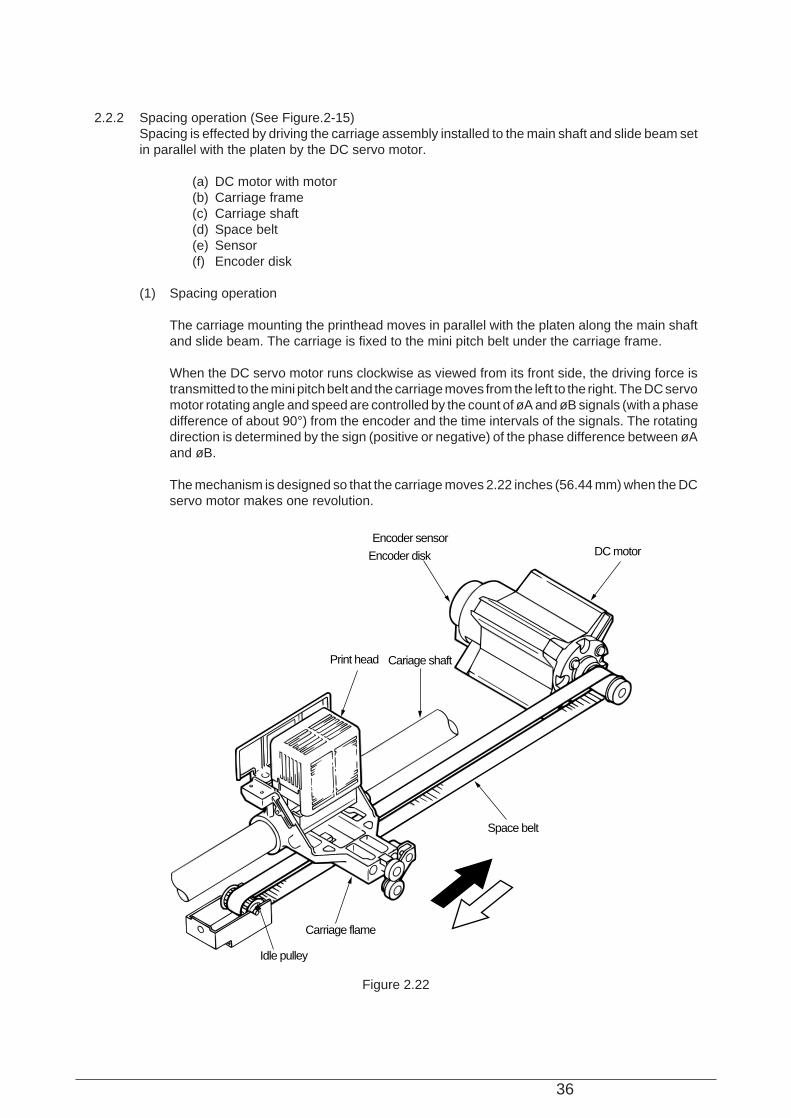
2.2.2 Spacing operation (See Figure.2-15)Spacing is effected by driving the carriage assembly installed to the main shaft and slide beam setin parallel with the platen by the DC servo motor.
(a) DC motor with motor(b) Carriage frame(c) Carriage shaft(d) Space belt(e) Sensor(f) Encoder disk
(1) Spacing operation
The carriage mounting the printhead moves in parallel with the platen along the main shaftand slide beam. The carriage is fixed to the mini pitch belt under the carriage frame.
When the DC servo motor runs clockwise as viewed from its front side, the driving force istransmitted to the mini pitch belt and the carriage moves from the left to the right. The DC servomotor rotating angle and speed are controlled by the count of øA and øB signals (with a phasedifference of about 90°) from the encoder and the time intervals of the signals. The rotatingdirection is determined by the sign (positive or negative) of the phase difference between øAand øB.
The mechanism is designed so that the carriage moves 2.22 inches (56.44 mm) when the DCservo motor makes one revolution.
Encoder sensor
Encoder disk
Print head Cariage shaft
Space belt
Carriage flame
Idle pulley
DC motor
Figure 2.22
37
2.2.3 Head gap adjustingThe auto gap adjusting mechanism automatically adjusts the space between the platen and printhead according to the thickness of papers. This mechanism does this driving the platen back andforth with the AG motor (pulse motor), and effects the auto gap motion after the reverse motion ofthe platen. The platen is reversed at power on or off line when cover open or paper end is detected,and the auto gap adjusting motion is performed when the printer returns to on line.When the printer is shifted to off line at power on or detection of paper end, the platen reverses tothe position that the space to the print head becomes wider than the thickness of paper (gap openposition).As the off line mode is released, shifted to on line after platen reverses, the AG motor drives theplaten to the direction that the space between the print head and platen becomes narrower.The rotational force of the AG motor moves the platen to the print head (in the direction that thespace becomes narrower) through various idle gears and adjusting cam.After that, the AG plate impinges on the paper, and the AG frame is deflected, changing the coregap of the auto gap sensor located on the AG frame. When the change of the core gap is detected,the AG motor stops rotating.Next, the AG motor reverse-rotates only a fixed step and stops. This allows the platen movebackward, obtaining an proper space with the print head.The forward an backward motion of the platen is driven by the adjusting cam being rotated, andthe platen is always pulled to the rear of the unit by the spring.
38
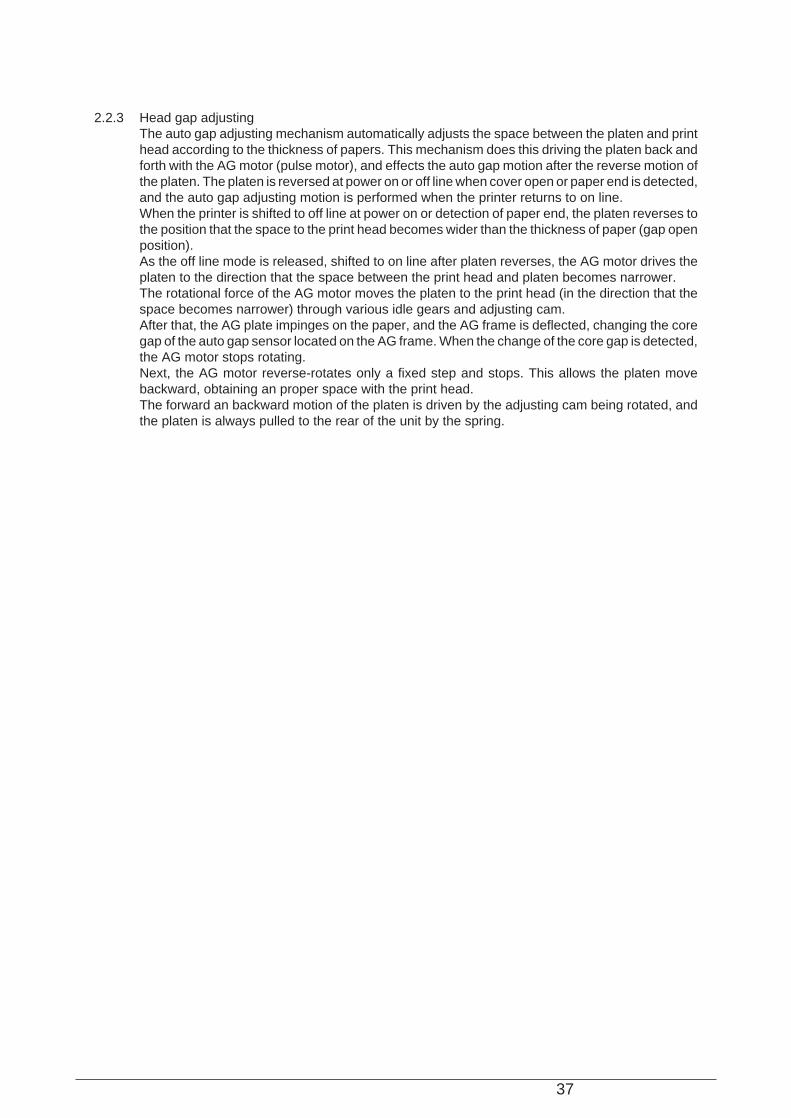
(1) AG detection mechanism
(2) AG sensor slit disk driving mechanism
Platen sheet guide
Eccentric collar
Moving direction of platen
Platen
Bearing
Cam roller
Core
Coil
EI sensor
Sensor frame
Deflecting direction of sensor frame
AG press plate
Carriage frame
Platen
Platen
BearingCum roller
AG motor(pulse motor)
Slit diskAG slit sensorEccentric collar
Moving direction of platen
Moving direction
Figure 2.23
Figure 2.24
39
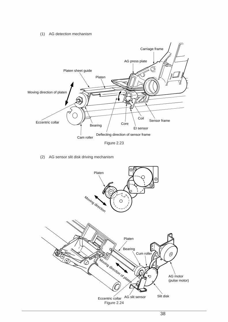
(3) AG detector detail drawing
Head
AG plate
Paper
AG sensor flame
Cor
e ga
p
AG
pla
tega
p
Ferrite core
Figure 2.25
40
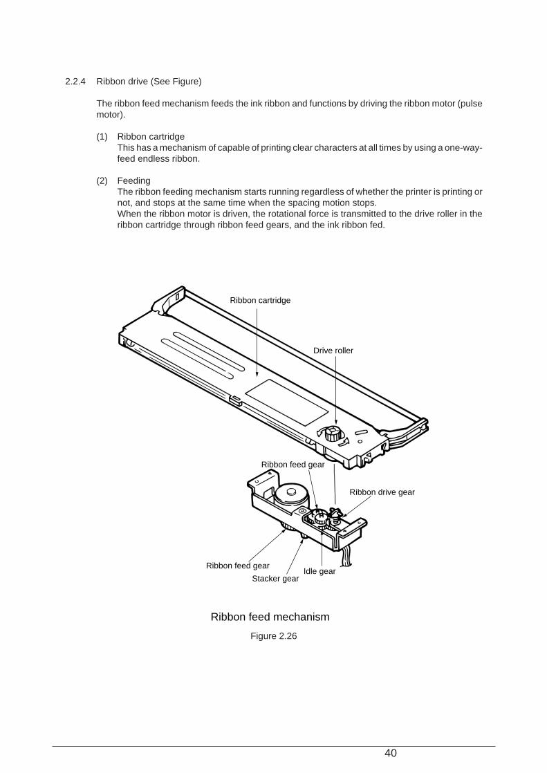
2.2.4 Ribbon drive (See Figure)
The ribbon feed mechanism feeds the ink ribbon and functions by driving the ribbon motor (pulsemotor).
(1) Ribbon cartridgeThis has a mechanism of capable of printing clear characters at all times by using a one-way-feed endless ribbon.
(2) FeedingThe ribbon feeding mechanism starts running regardless of whether the printer is printing ornot, and stops at the same time when the spacing motion stops.When the ribbon motor is driven, the rotational force is transmitted to the drive roller in theribbon cartridge through ribbon feed gears, and the ink ribbon fed.
Ribbon cartridge
Ribbon feed gear
Stacker gearIdle gear
Ribbon feed gear
Ribbon drive gear
Drive roller
Ribbon feed mechanism
Figure 2.26
41
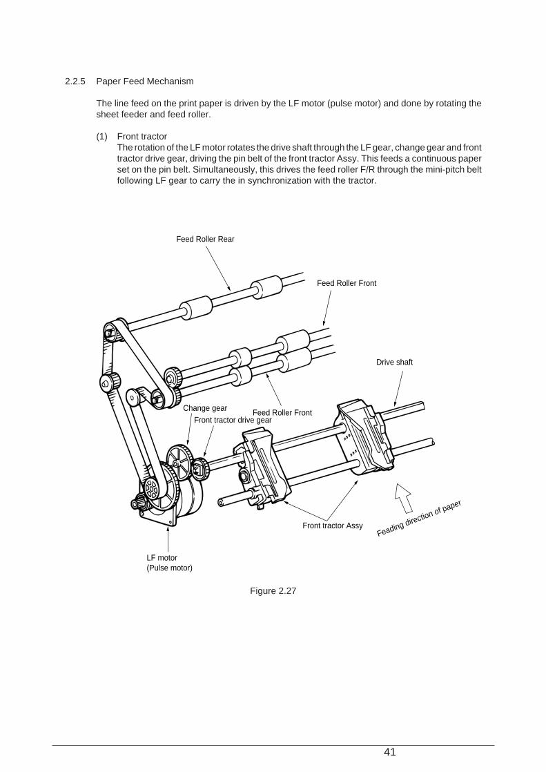
2.2.5 Paper Feed Mechanism
The line feed on the print paper is driven by the LF motor (pulse motor) and done by rotating thesheet feeder and feed roller.
(1) Front tractorThe rotation of the LF motor rotates the drive shaft through the LF gear, change gear and fronttractor drive gear, driving the pin belt of the front tractor Assy. This feeds a continuous paperset on the pin belt. Simultaneously, this drives the feed roller F/R through the mini-pitch beltfollowing LF gear to carry the in synchronization with the tractor.
Feed Roller Rear
Feed Roller Front
Feed Roller Front
Drive shaft
Front tractor Assy
LF motor(Pulse motor)
Change gearFront tractor drive gear
Feading direction of paper
Figure 2.27
42
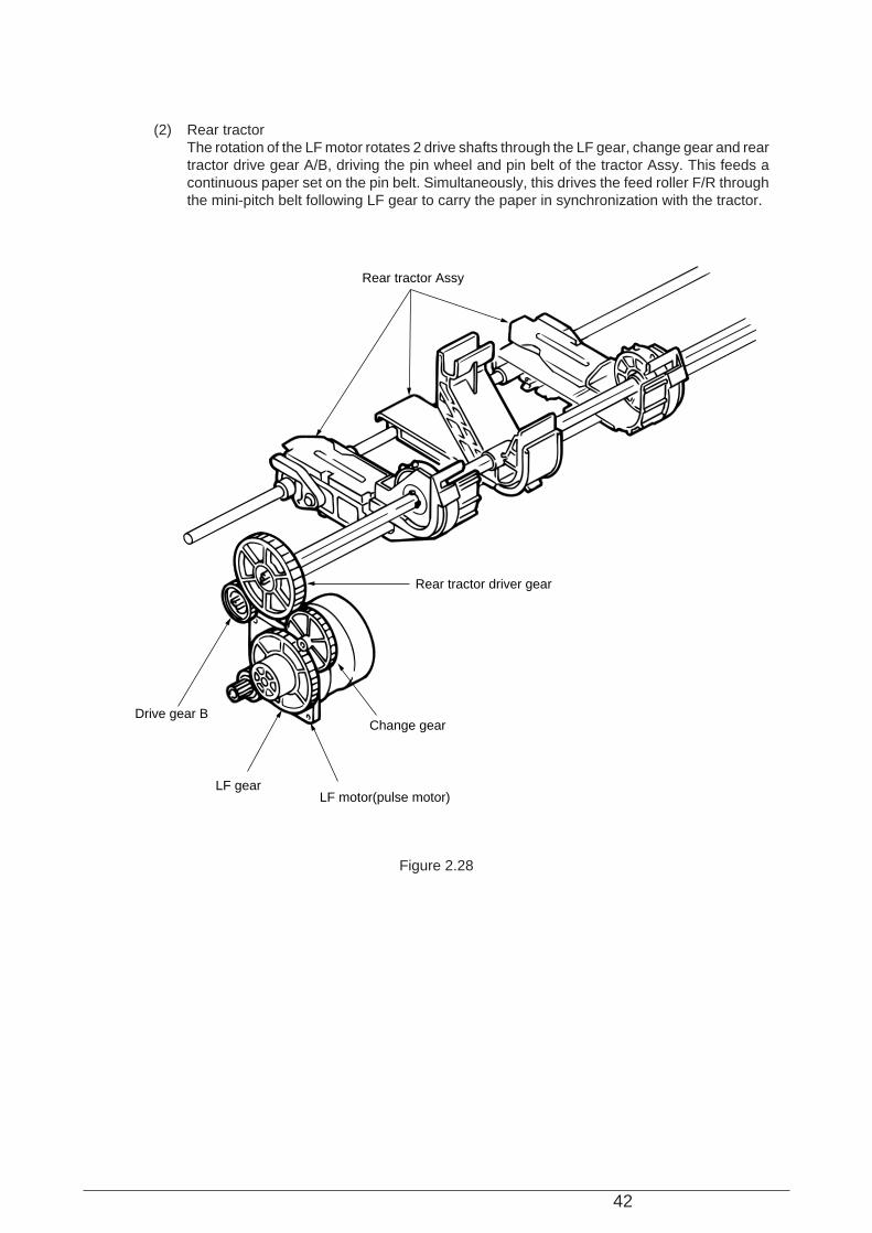
(2) Rear tractorThe rotation of the LF motor rotates 2 drive shafts through the LF gear, change gear and reartractor drive gear A/B, driving the pin wheel and pin belt of the tractor Assy. This feeds acontinuous paper set on the pin belt. Simultaneously, this drives the feed roller F/R throughthe mini-pitch belt following LF gear to carry the paper in synchronization with the tractor.
Rear tractor Assy
Drive gear B
Rear tractor driver gear
LF gearLF motor(pulse motor)
Change gear
Figure 2.28
43
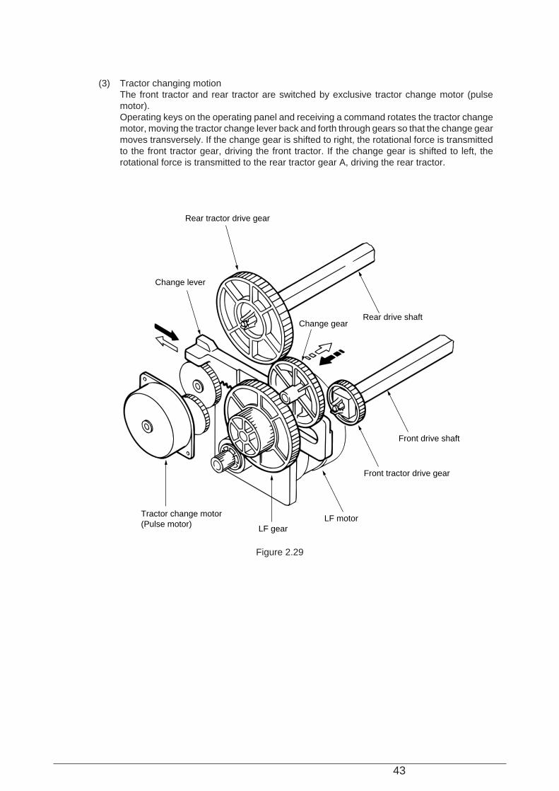
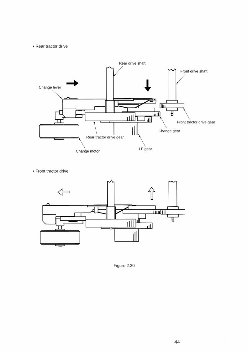
(3) Tractor changing motionThe front tractor and rear tractor are switched by exclusive tractor change motor (pulsemotor).Operating keys on the operating panel and receiving a command rotates the tractor changemotor, moving the tractor change lever back and forth through gears so that the change gearmoves transversely. If the change gear is shifted to right, the rotational force is transmittedto the front tractor gear, driving the front tractor. If the change gear is shifted to left, therotational force is transmitted to the rear tractor gear A, driving the rear tractor.
Rear tractor drive gear
Change lever
Rear drive shaftChange gear
Front drive shaft
Front tractor drive gear
LF motorLF gear
Tractor change motor(Pulse motor)
Figure 2.29
44
Front drive shaft
Front tractor drive gear
Change gear
LF gear
Rear tractor drive gear
Change motor
Change lever
Rear drive shaft
• Rear tractor drive
• Front tractor drive
Figure 2.30
45
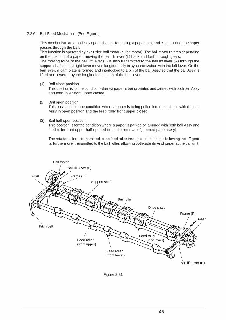
2.2.6 Bail Feed Mechanism (See Figure )
This mechanism automatically opens the bail for pulling a paper into, and closes it after the paperpasses through the bail.This function is operated by exclusive bail motor (pulse motor). The bail motor rotates dependingon the position of a paper, moving the bail lift lever (L) back and forth through gears.The moving force of the bail lift lever (L) is also transmitted to the bail lift lever (R) through thesupport shaft, so the right lever moves longitudinally in synchronization with the left lever. On thebail lever, a cam plate is formed and interlocked to a pin of the bail Assy so that the bail Assy islifted and lowered by the longitudinal motion of the bail lever.
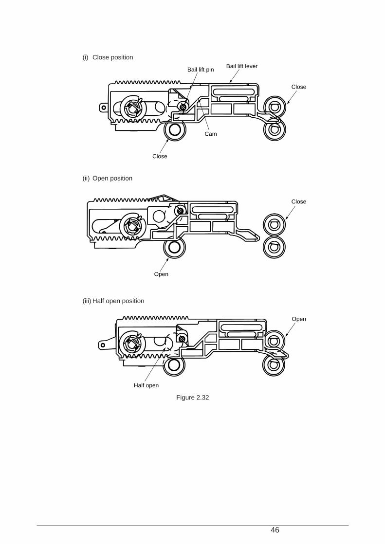
(1) Bail close positionThis position is for the condition where a paper is being printed and carried with both bail Assyand feed roller front upper closed.
(2) Bail open positionThis position is for the condition where a paper is being pulled into the bail unit with the bailAssy in open position and the feed roller front upper closed.
(3) Bail half open positionThis position is for the condition where a paper is parked or jammed with both bail Assy andfeed roller front upper half-opened (to make removal of jammed paper easy).
The rotational force transmitted to the feed roller through mini-pitch belt following the LF gearis, furthermore, transmitted to the bail roller, allowing both-side drive of paper at the bail unit.
Gear
Bail motor
Bail lift lever (L)
Frame (L)
Support shaft
Bail roller
Drive shaft
Frame (R)
Gear
Bail lift lever (R)
Feed roller(front lower)
Feed roller(front upper)
Feed roller (rear lower)
Pitch belt
Figure 2.31
46
(i) Close position
(ii) Open position
(iii) Half open position
Half open
Open
Open
Close
Close
Close
Cam
Bail lift pinBail lift lever
Figure 2.32
47
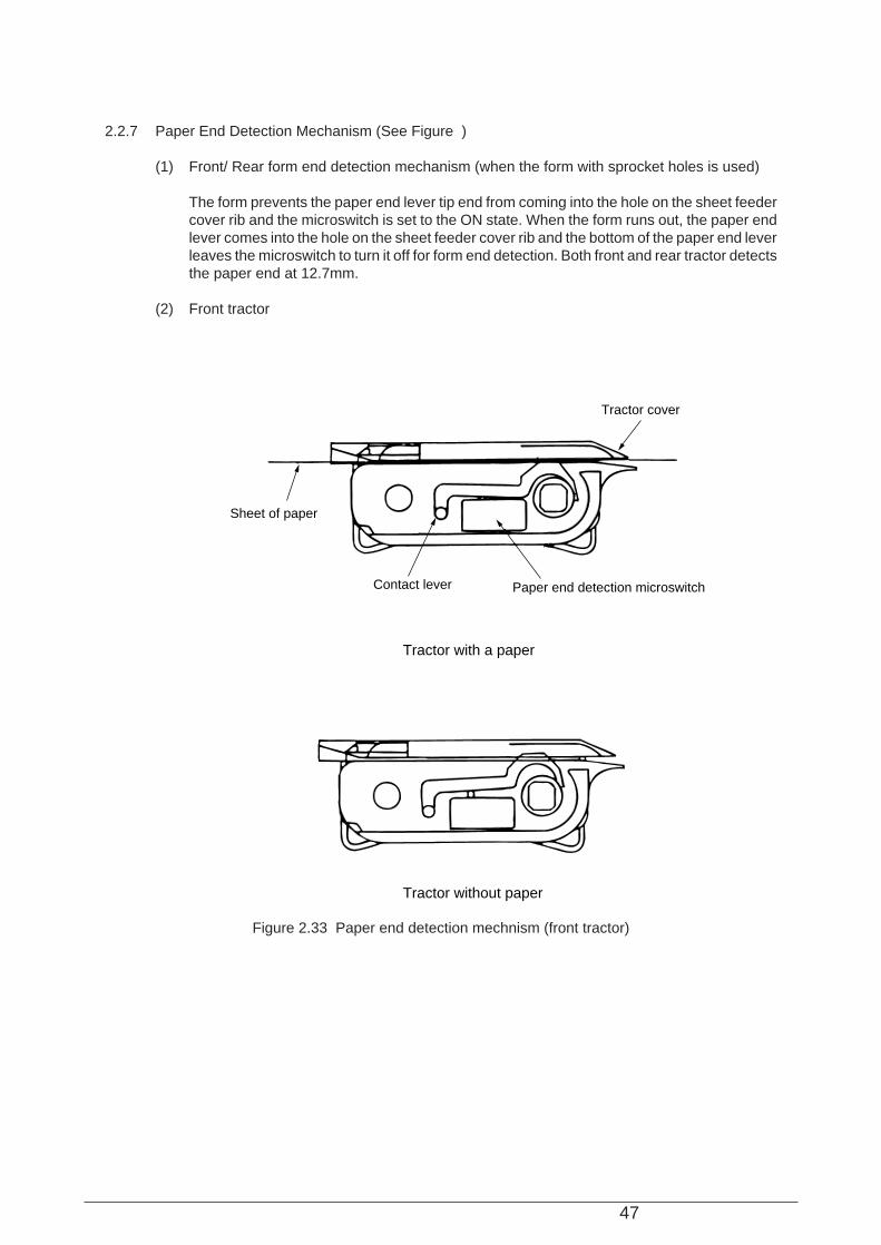
2.2.7 Paper End Detection Mechanism (See Figure )
(1) Front/ Rear form end detection mechanism (when the form with sprocket holes is used)
The form prevents the paper end lever tip end from coming into the hole on the sheet feedercover rib and the microswitch is set to the ON state. When the form runs out, the paper endlever comes into the hole on the sheet feeder cover rib and the bottom of the paper end leverleaves the microswitch to turn it off for form end detection. Both front and rear tractor detectsthe paper end at 12.7mm.
(2) Front tractor
Sheet of paper
Tractor cover
Contact lever Paper end detection microswitch
Tractor with a paper
Tractor without paper
Figure 2.33 Paper end detection mechnism (front tractor)

48
(3) Rear tractor
Form
Sheet feed cover rib
Pin tractor L
Paper end lever
Micro switch
Figure 2.34 Rear form end detection mechanism
49
(2) Do not try disassembly as long as the printer is operating normally.
(3) Do not remove unnecessary parts: try to keep disassembly to a minimum.
(4) Use specified service tools.
(5) When disassembling, follow the determined sequence. Otherwise, parts may be damaged.
(6) Since screws, collars and other small parts are likely to be lost, they should temporarily beattached to the original positions.
(7) When handling ICs such as microprocessors, ROM and RAM, and circuit boards, do not weargloves that are likely to generate static electricity.
(8) Do not place printed circuit boards directly on the equipment or floor.
(9) If adjustment is specified in the middle of installation, follow the instructions.
3. PARTS REPLACEMENT
The section explains the procedures for replacement of parts, assemblies, and units in the field.Only the removal procedures are explained here. Reverse the procedure for the installation.
3.1 Precautions for Parts Replacement
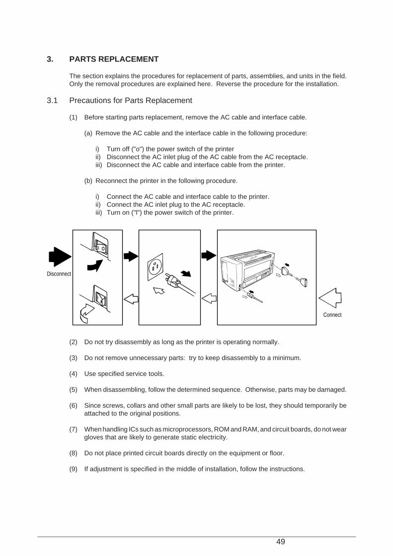
(1) Before starting parts replacement, remove the AC cable and interface cable.
(a) Remove the AC cable and the interface cable in the following procedure:
i) Turn off ("o") the power switch of the printerii) Disconnect the AC inlet plug of the AC cable from the AC receptacle.iii) Disconnect the AC cable and interface cable from the printer.
(b) Reconnect the printer in the following procedure.
i) Connect the AC cable and interface cable to the printer.ii) Connect the AC inlet plug to the AC receptacle.iii) Turn on ("l") the power switch of the printer.
Disconnect
Connect
50
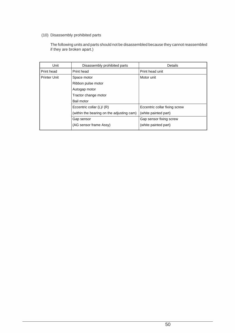
(10) Disassembly prohibited parts
The following units and parts should not be disassembled because they cannot reassembledif they are broken apart.)
Unit
Print head
Printer Unit
Disassembly prohibited parts
Print head
Space motor
Ribbon pulse motor
Autogap motor
Tractor change motor
Bail motor
Eccentric collar (L)/ (R)
(within the bearing on the adjusting cam)
Gap sensor
(AG sensor frame Assy)
Details
Print head unit
Motor unit
Eccentric collar fixing screw
(white painted part)
Gap sensor fixing screw
(white painted part)
51
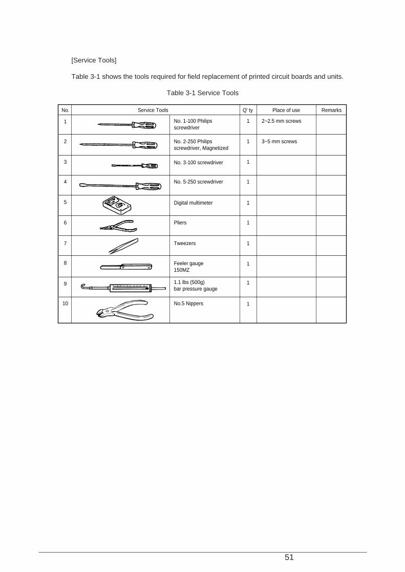
[Service Tools]
Table 3-1 shows the tools required for field replacement of printed circuit boards and units.
Table 3-1 Service Tools
No.
No. 1-100 Philipsscrewdriver
Q' ty Place of use RemarksService Tools
1
2
3
4
5
6
8
No. 2-250 Philipsscrewdriver, Magnetized
No. 3-100 screwdriver
No. 5-250 screwdriver
Digital multimeter
Pliers
1
1
1
1
1
1
2~2.5 mm screws
3~5 mm screws
9
Tweezers
Feeler gauge150MZ
7 1
1
1.1 lbs (500g)bar pressure gauge
1
10 No.5 Nippers 1
52
Figure 3-1
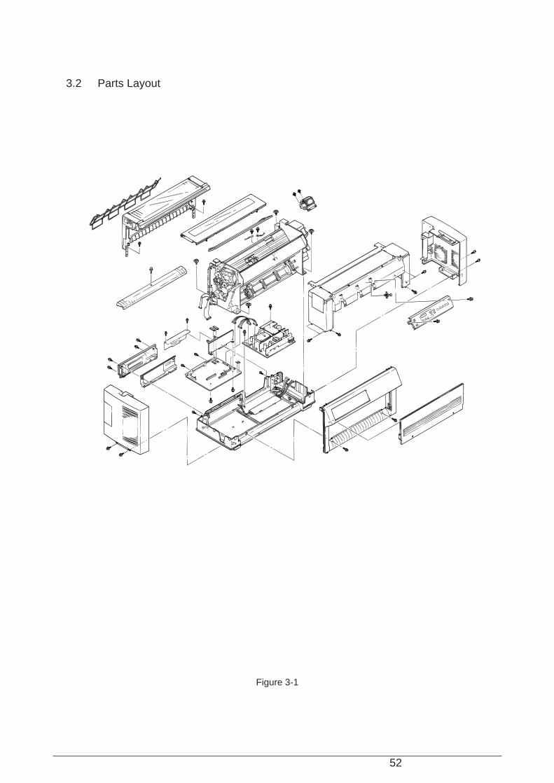
3.2 Parts Layout

53
3.3 How to Change Parts
This section explains how to change parts and assemblies appearing in the disassembly diagrambelow.
54
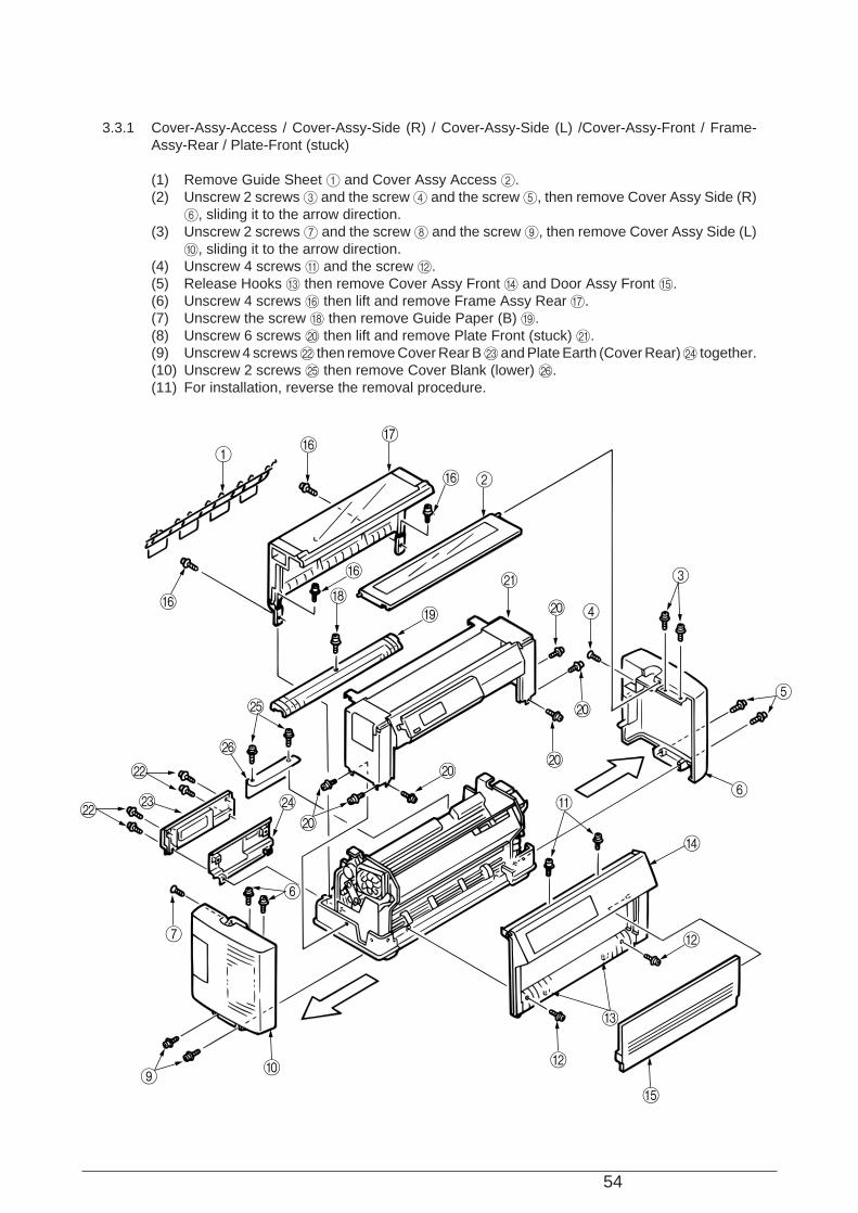
3.3.1 Cover-Assy-Access / Cover-Assy-Side (R) / Cover-Assy-Side (L) /Cover-Assy-Front / Frame-Assy-Rear / Plate-Front (stuck)
(1) Remove Guide Sheet 1 and Cover Assy Access 2.(2) Unscrew 2 screws 3 and the screw 4 and the screw 5, then remove Cover Assy Side (R)
6, sliding it to the arrow direction.(3) Unscrew 2 screws 7 and the screw 8 and the screw 9, then remove Cover Assy Side (L)
0, sliding it to the arrow direction.(4) Unscrew 4 screws A and the screw B.(5) Release Hooks C then remove Cover Assy Front D and Door Assy Front E.(6) Unscrew 4 screws F then lift and remove Frame Assy Rear G.(7) Unscrew the screw H then remove Guide Paper (B) I.(8) Unscrew 6 screws J then lift and remove Plate Front (stuck) K.(9) Unscrew 4 screws L then remove Cover Rear B M and Plate Earth (Cover Rear) N together.(10) Unscrew 2 screws O then remove Cover Blank (lower) P.(11) For installation, reverse the removal procedure.
GF
F
F
J
B
A
C
J
I
N
6
9
P
O
M
H
1
2
3
5
6
D
K
4J
J
7
0 B
E
J
F
L
L

55
3.3.2 Printer Unit
(1) Remove Cover Assy Access / Cover Assy Side (R) / Cover Assy Side (L) /Cover Assy Front/ Frame Assy Rear / Plate Front (stuck). (See 3.3.1)
(2) Unscrew 4 screws 2 which fix Printer Unit 1.(3) Unplug I/F Connecting Cable 4 and Head Cable 5 from Control Board 3.(4) Unplug the connector to Power Supply Assy 6 and unscrew 2 screws 8, then remove FG
Wires 9.(5) Unplug Junction Board Cord 0 from Junction Board (PRA Printed Board)(CN1).(6) Unplug SP Slit Sensor Cord A.(7) With the handle B held, lift and remove Printer Unit 1.
(Note on Installation) 1. When lowering Printer Unit, prevent connection cords/cables from being caught under the unit.
(Lifting and lowering Printer Unit require 2 or more maintenance personnel.)
4
2
1
9
9
82
B
B
5
3
6
0
A
CN1
56
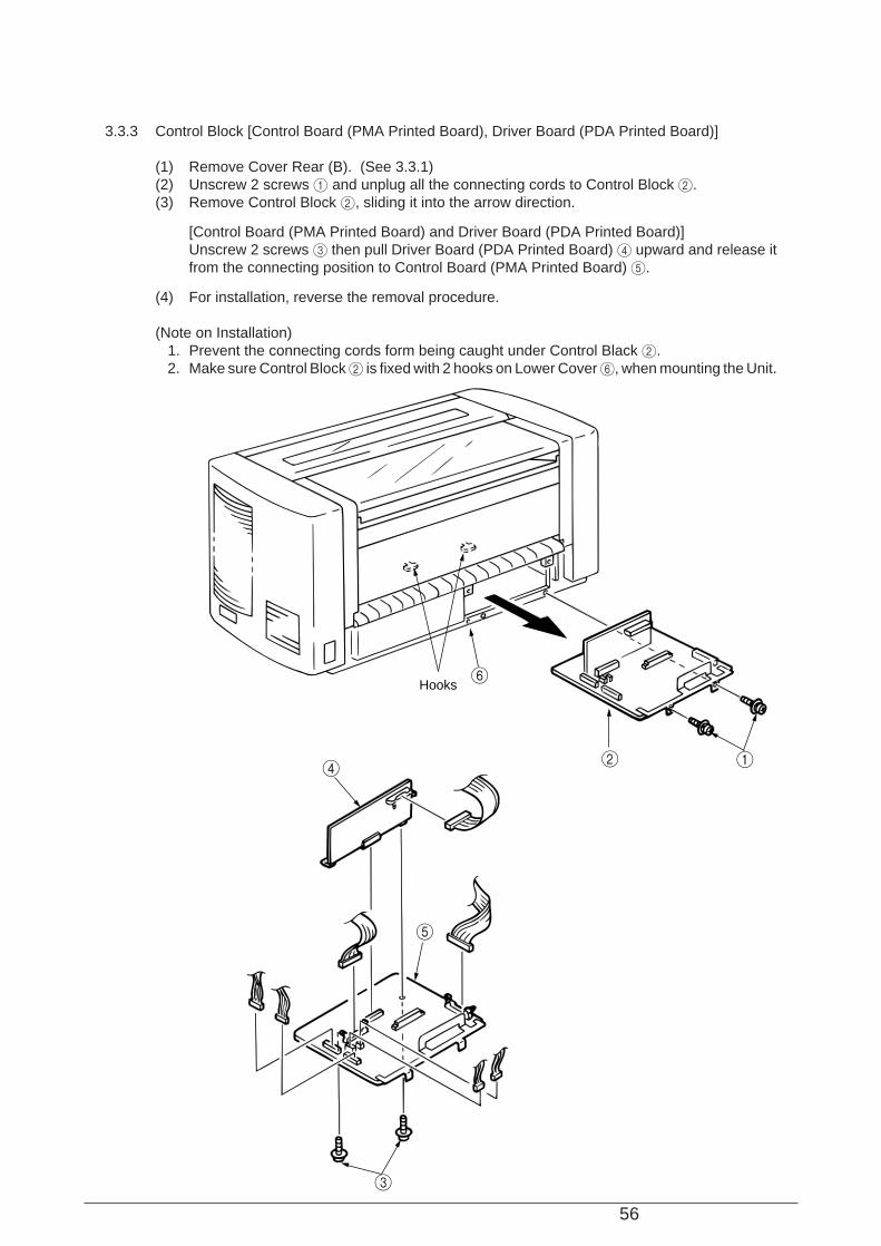
3.3.3 Control Block [Control Board (PMA Printed Board), Driver Board (PDA Printed Board)]
(1) Remove Cover Rear (B). (See 3.3.1)(2) Unscrew 2 screws 1 and unplug all the connecting cords to Control Block 2.(3) Remove Control Block 2, sliding it into the arrow direction.
[Control Board (PMA Printed Board) and Driver Board (PDA Printed Board)]Unscrew 2 screws 3 then pull Driver Board (PDA Printed Board) 4 upward and release itfrom the connecting position to Control Board (PMA Printed Board) 5.
(4) For installation, reverse the removal procedure.
(Note on Installation) 1. Prevent the connecting cords form being caught under Control Black 2. 2. Make sure Control Block 2 is fixed with 2 hooks on Lower Cover 6, when mounting the Unit.
4
5
3
6
12
Hooks
57
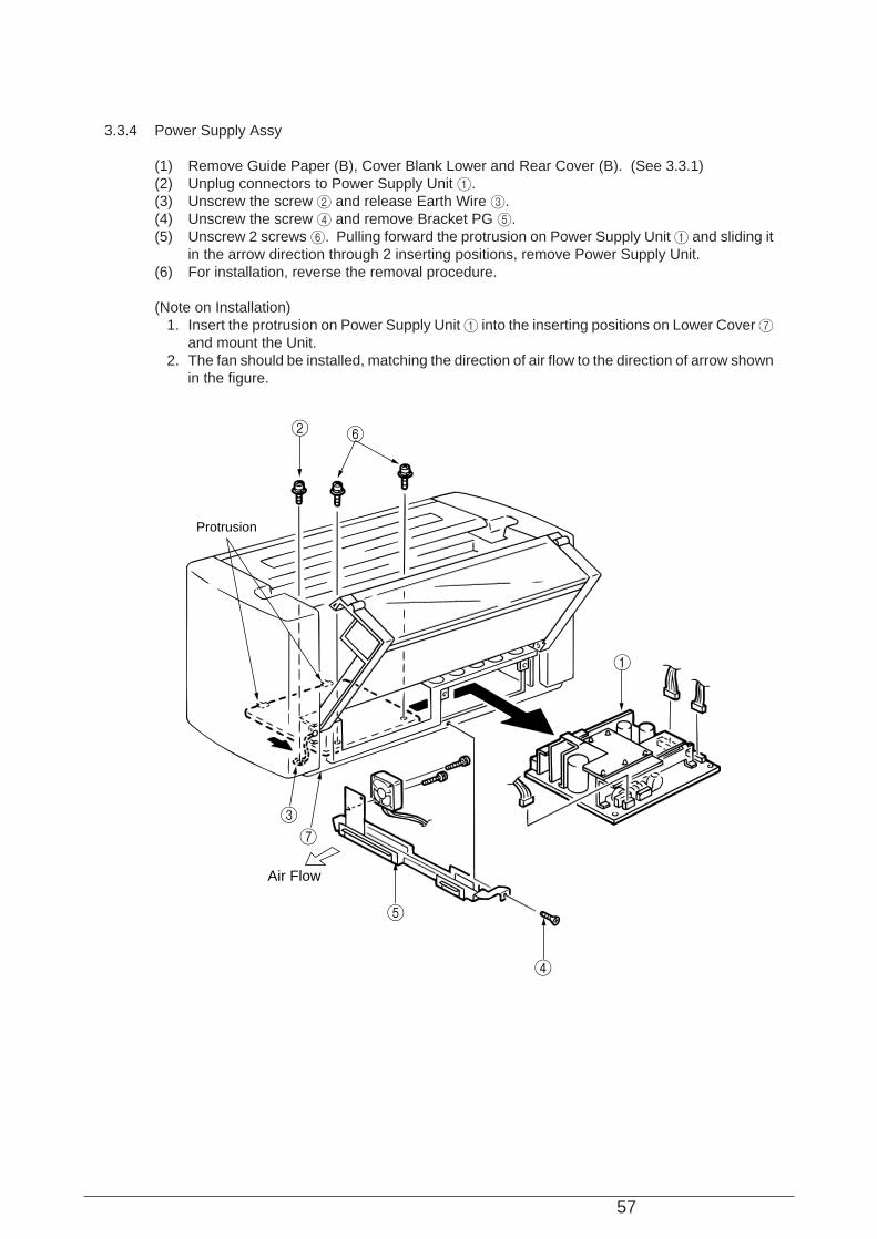
3.3.4 Power Supply Assy
(1) Remove Guide Paper (B), Cover Blank Lower and Rear Cover (B). (See 3.3.1)(2) Unplug connectors to Power Supply Unit 1.(3) Unscrew the screw 2 and release Earth Wire 3.(4) Unscrew the screw 4 and remove Bracket PG 5.(5) Unscrew 2 screws 6. Pulling forward the protrusion on Power Supply Unit 1 and sliding it
in the arrow direction through 2 inserting positions, remove Power Supply Unit.(6) For installation, reverse the removal procedure.
(Note on Installation) 1. Insert the protrusion on Power Supply Unit 1 into the inserting positions on Lower Cover 7
and mount the Unit. 2. The fan should be installed, matching the direction of air flow to the direction of arrow shown
in the figure.
1
2
3
7
4
5
6
Protrusion
Air Flow
58
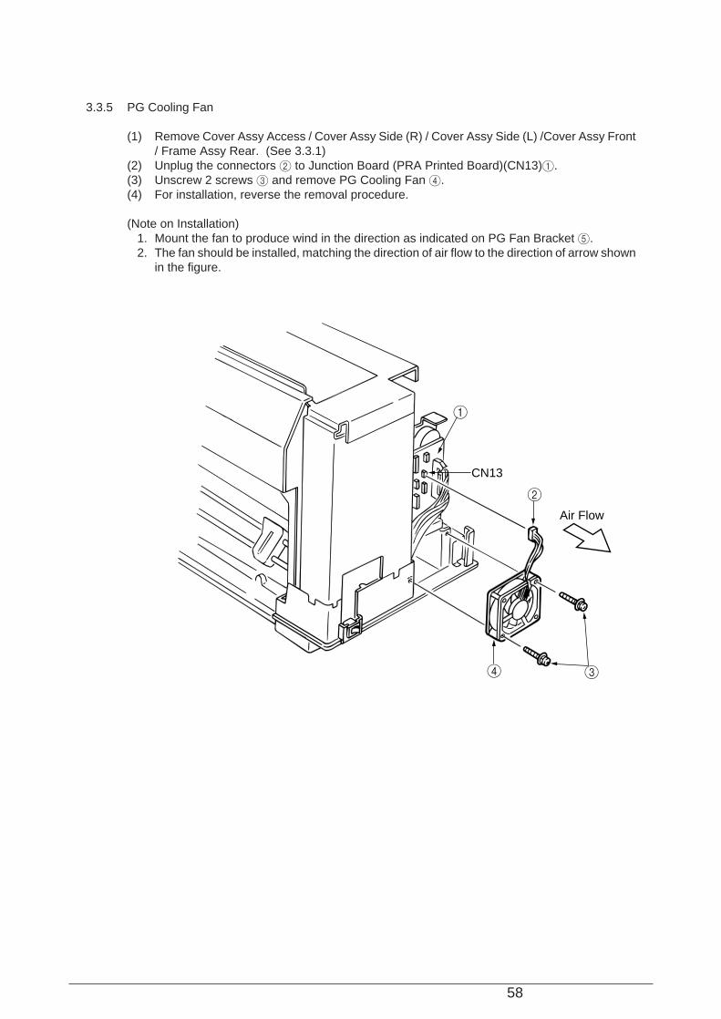
3.3.5 PG Cooling Fan
(1) Remove Cover Assy Access / Cover Assy Side (R) / Cover Assy Side (L) /Cover Assy Front/ Frame Assy Rear. (See 3.3.1)
(2) Unplug the connectors 2 to Junction Board (PRA Printed Board)(CN13)1.(3) Unscrew 2 screws 3 and remove PG Cooling Fan 4.(4) For installation, reverse the removal procedure.
(Note on Installation) 1. Mount the fan to produce wind in the direction as indicated on PG Fan Bracket 5. 2. The fan should be installed, matching the direction of air flow to the direction of arrow shown
in the figure.
1
2
34
CN13
Air Flow
59
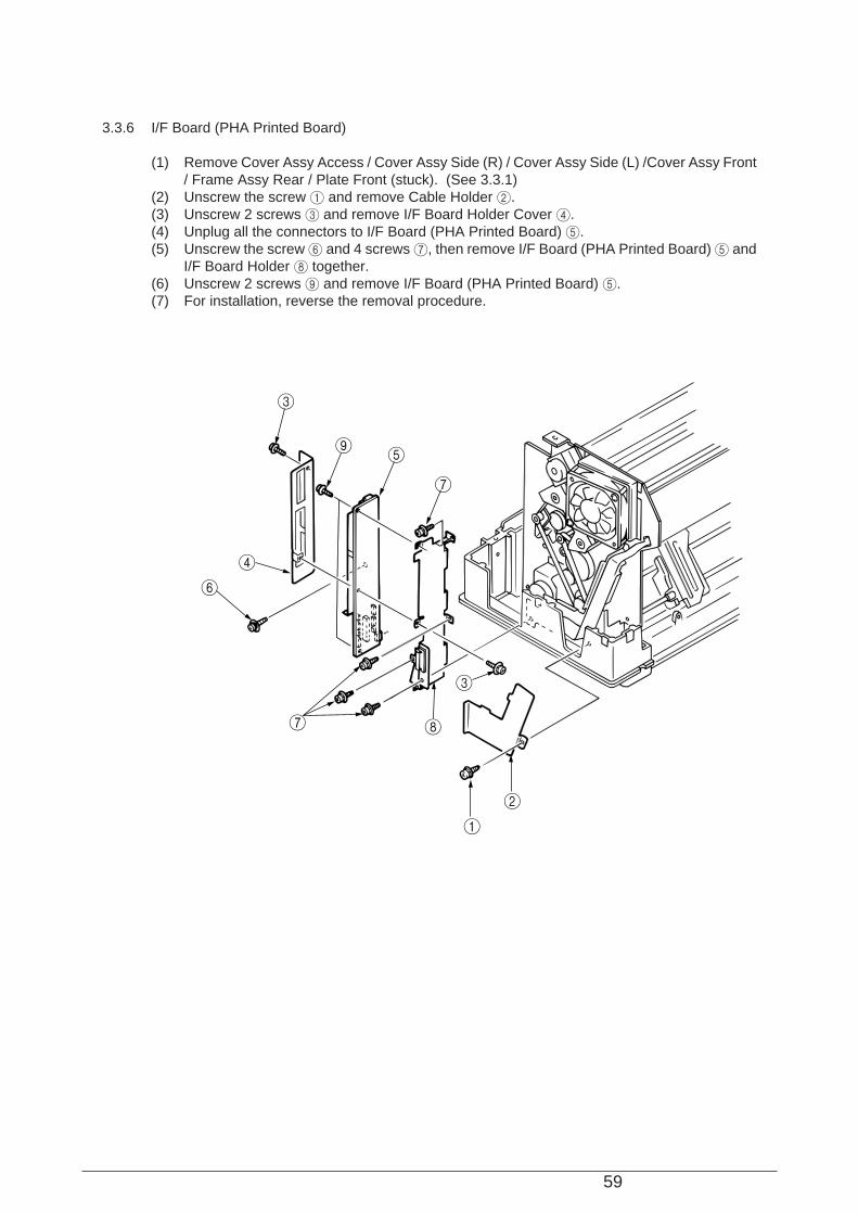
3.3.6 I/F Board (PHA Printed Board)
(1) Remove Cover Assy Access / Cover Assy Side (R) / Cover Assy Side (L) /Cover Assy Front/ Frame Assy Rear / Plate Front (stuck). (See 3.3.1)
(2) Unscrew the screw 1 and remove Cable Holder 2.(3) Unscrew 2 screws 3 and remove I/F Board Holder Cover 4.(4) Unplug all the connectors to I/F Board (PHA Printed Board) 5.(5) Unscrew the screw 6 and 4 screws 7, then remove I/F Board (PHA Printed Board) 5 and
I/F Board Holder 8 together.(6) Unscrew 2 screws 9 and remove I/F Board (PHA Printed Board) 5.(7) For installation, reverse the removal procedure.
1
2
3
3
4
5
7
6
7 8
9
60
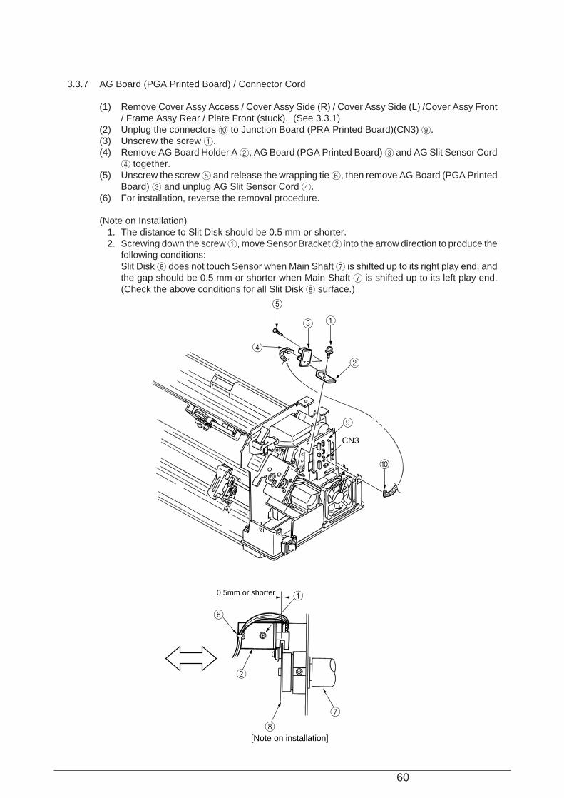
3.3.7 AG Board (PGA Printed Board) / Connector Cord
(1) Remove Cover Assy Access / Cover Assy Side (R) / Cover Assy Side (L) /Cover Assy Front/ Frame Assy Rear / Plate Front (stuck). (See 3.3.1)
(2) Unplug the connectors 0 to Junction Board (PRA Printed Board)(CN3) 9.(3) Unscrew the screw 1.(4) Remove AG Board Holder A 2, AG Board (PGA Printed Board) 3 and AG Slit Sensor Cord
4 together.(5) Unscrew the screw 5 and release the wrapping tie 6, then remove AG Board (PGA Printed
Board) 3 and unplug AG Slit Sensor Cord 4.(6) For installation, reverse the removal procedure.
(Note on Installation) 1. The distance to Slit Disk should be 0.5 mm or shorter. 2. Screwing down the screw 1, move Sensor Bracket 2 into the arrow direction to produce the
following conditions:Slit Disk 8 does not touch Sensor when Main Shaft 7 is shifted up to its right play end, andthe gap should be 0.5 mm or shorter when Main Shaft 7 is shifted up to its left play end.(Check the above conditions for all Slit Disk 8 surface.)
5
4
3
2
9
1
0
1
2
6
7
8[Note on installation]
0.5mm or shorter
CN3
61
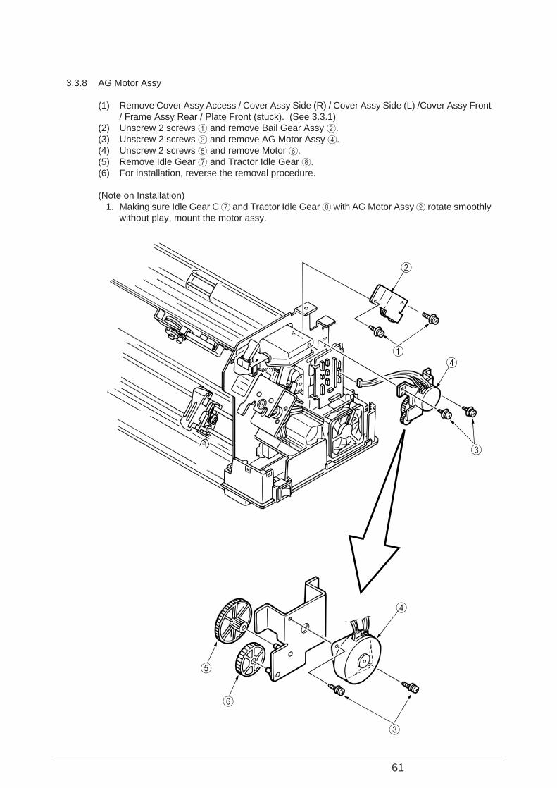
3.3.8 AG Motor Assy
(1) Remove Cover Assy Access / Cover Assy Side (R) / Cover Assy Side (L) /Cover Assy Front/ Frame Assy Rear / Plate Front (stuck). (See 3.3.1)
(2) Unscrew 2 screws 1 and remove Bail Gear Assy 2.(3) Unscrew 2 screws 3 and remove AG Motor Assy 4.(4) Unscrew 2 screws 5 and remove Motor 6.(5) Remove Idle Gear 7 and Tractor Idle Gear 8.(6) For installation, reverse the removal procedure.
(Note on Installation) 1. Making sure Idle Gear C 7 and Tractor Idle Gear 8 with AG Motor Assy 2 rotate smoothly
without play, mount the motor assy.
6
5
4
3
1
2
4
3
62
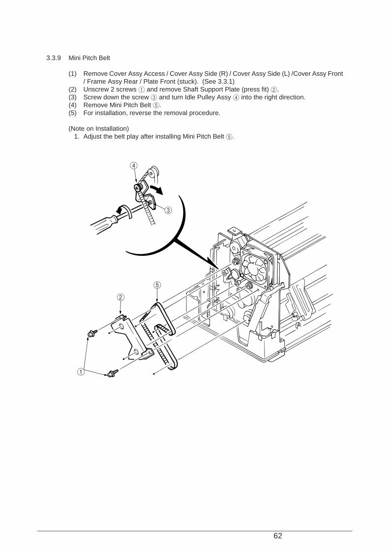
3.3.9 Mini Pitch Belt
(1) Remove Cover Assy Access / Cover Assy Side (R) / Cover Assy Side (L) /Cover Assy Front/ Frame Assy Rear / Plate Front (stuck). (See 3.3.1)
(2) Unscrew 2 screws 1 and remove Shaft Support Plate (press fit) 2.(3) Screw down the screw 3 and turn Idle Pulley Assy 4 into the right direction.(4) Remove Mini Pitch Belt 5.(5) For installation, reverse the removal procedure.
(Note on Installation) 1. Adjust the belt play after installing Mini Pitch Belt 5.
1
2
5
3
4

63
3.3.10 Tractor Change Motor Assy
(1) Remove Cover Assy Access / Cover Assy Side (R) / Cover Assy Side (L) /Cover Assy Front/ Frame Assy Rear / Plate Front (stuck). (See 3.3.1)
(2) Remove Printer Unit. (See 3.3.2)(3) Remove I/F Board. (See 3.3.6)(4) Release the cords from Cord Clamp 3 on the cord route.(5) Unscrew 2 screws 4 and remove Cable Holder 5.(6) Unscrew the screw 6 and cut the wrapping tie 7.(7) Remove Micro Switch 8.(8) Unscrew 2 screws 9 and remove Tractor Change Motor Assy 0.(9) Remove E rings A and the gear B.(10) Unscrew 2 screws C and remove Motor D.(11) For installation, reverse the removal procedure.
B
0
B
DC
6
8
7
9
9
4
4
5
A
View A
View A

64
3.3.11 Bail Motor Assy
(1) Remove Cover Assy Access / Cover Assy Side (R) / Cover Assy Side (L) /Cover Assy Front/ Frame Assy Rear / Plate Front (stuck). (See 3.3.1)
(2) Unplug the connectors 1 from I/F Board (PHA Printed Board)(CN2) B.(3) Unplug the connectors A from I/F Board (PHA Printed Board)(CN11) B.(4) Release the cords from the cord clamps on the cord route.(5) Unscrew the screw 2 and cut the wrapping tie.(6) Remove Micro Switch 3.(7) Unscrew 2 screws 4 and remove Bail Motor Assy 5.(8) Unscrew 2 screws 6 and remove the motor 7.(9) Remove E rings 8 and 2 gears 9 and 0.(10) For installation, reverse the removal procedure.
6
0
9
8
2
3
7
4
5
1
B
A
Wrapping tie

65
3.3.12 LF Motor Assy
(1) Remove Cover Assy Access / Cover Assy Side (R) / Cover Assy Side (L) /Cover Assy Front/ Frame Assy Rear / Plate Front (stuck). (See 3.3.1)
(2) Remove I/F Board. (See 3.3.6)(3) Remove Printer Unit. (See3.3.2)(4) Remove Tractor Change Motor Assy. (See3.3.10)(5) Unscrew 3 screws 1 and remove LF Motor 2.(6) For installation, reverse the removal procedure.
(Note on Installation) 1. LF Motor Assy 2 should be mounted with the cord route as shown below.
2
1
[ LF Motor Assy Cord Route Fig. ]
66
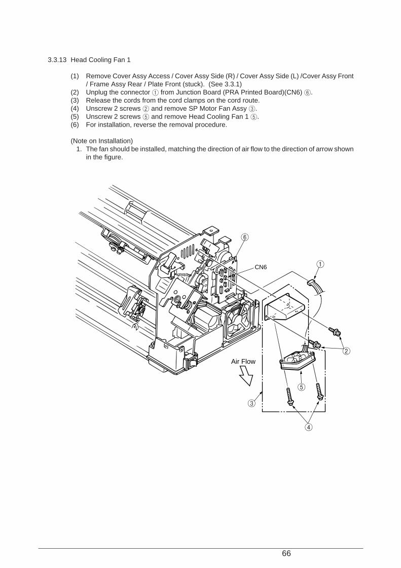
3.3.13 Head Cooling Fan 1
(1) Remove Cover Assy Access / Cover Assy Side (R) / Cover Assy Side (L) /Cover Assy Front/ Frame Assy Rear / Plate Front (stuck). (See 3.3.1)
(2) Unplug the connector 1 from Junction Board (PRA Printed Board)(CN6) 6.(3) Release the cords from the cord clamps on the cord route.(4) Unscrew 2 screws 2 and remove SP Motor Fan Assy 3.(5) Unscrew 2 screws 5 and remove Head Cooling Fan 1 5.(6) For installation, reverse the removal procedure.
(Note on Installation) 1. The fan should be installed, matching the direction of air flow to the direction of arrow shown
in the figure.
1
6
2
3
4
5
CN6
Air Flow

67
3.3.14 Head Cooling Fan 2
(1) Remove Cover Assy Access / Cover Assy Side (R) / Cover Assy Side (L) /Cover Assy Front/ Frame Assy Rear / Plate Front (stuck). (See 3.3.1)
(2) Unscrew the screw 1 and remove Cable Holder Cover 2.(3) Unplug the connector 3 from I/F Board (PHA Printed Board)(CN6) 6.(4) Release the cords from the cord clamps on the cord route.(5) Unscrew 2 screws 4 and remove Head Cleaning Fan 2 5.(6) For installation, reverse the removal procedure.
(Note on Installation) 1. The fan should be installed, matching the direction of air flow to the direction of arrow shown
in the figure.
1
2
4
4
5
3
6
Air Flow

68
3.3.15 Space Motor
(1) Remove Cover Assy Access / Cover Assy Side (R) / Cover Assy Side (L) /Cover Assy Front/ Frame Assy Rear / Plate Front (stuck). (See 3.3.1)
(2) Remove Printer Unit. (See 3.3.2)(3) Remove the stopper 1.(4) Screw down 2 fixing screws 2 on Idle Pulley Bracket. Move the pulley into the arrow direction
to loose the belt, then fasten the screws.(5) Remove PG Cooling Fan. (See 3.3.5)(6) Unscrew 2 screws 4 and remove PG Fan Bracket 5.(7) Unplug connectors 7 to Interlock Switch Cord Assy B.(8) Unplug connectors 8, 9 to Interlock Switch 0, and release the cords from the clamps
on the cord route.(9) Unscrew 1 screws C and remove FG Mesh 3.(10) Unscrew 4 screws A and remove Space Motor 6.(11) For installation, reverse the removal procedure.
(Note on Installation) 1. After assembling the motor, adjust the position of the idle pulley bracket with screw 2 so that
the space belt should be positioned at the center between the idle pulley and motor pulley,and the vertical fluctuation of belt be 0.5mm or less when the carriage is shifted to right andleft. When the carriage is shifted to right and left, press the interlock switch 0 off so that theload of shifting it can be reduced.
8
A
A
9
0
1
2
2
B7
6
3
C
45
OFF
Idle Pulley Bracket
0.5m
m o
r le
ss
0.5m
m o
r le
ss
Junction Board
BrackBlew
GreenRed
Wiring of interlok swith
69
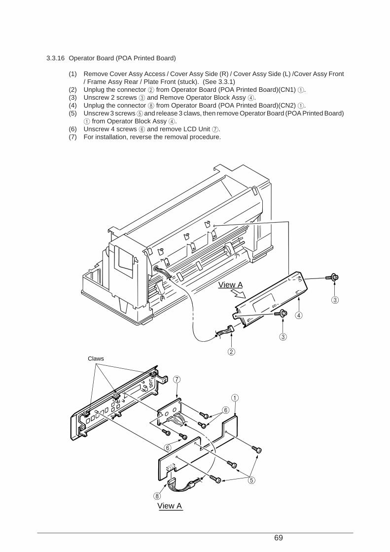
3.3.16 Operator Board (POA Printed Board)
(1) Remove Cover Assy Access / Cover Assy Side (R) / Cover Assy Side (L) /Cover Assy Front/ Frame Assy Rear / Plate Front (stuck). (See 3.3.1)
(2) Unplug the connector 2 from Operator Board (POA Printed Board)(CN1) 1.(3) Unscrew 2 screws 3 and Remove Operator Block Assy 4.(4) Unplug the connector 8 from Operator Board (POA Printed Board)(CN2) 1.(5) Unscrew 3 screws 5 and release 3 claws, then remove Operator Board (POA Printed Board)
1 from Operator Block Assy 4.(6) Unscrew 4 screws 6 and remove LCD Unit 7.(7) For installation, reverse the removal procedure.
View A
View A
7
6
6
8
2
3
4
3
5
1
Claws

70
3.3.17 Ribbon Feed Assy
(1) Remove Cover Assy Access / Cover Assy Side (R) / Cover Assy Side (L) /Cover Assy Front/ Frame Assy Rear / Plate Front (stuck). (See 3.3.1)
(2) Unplug the connector 1 from Junction Board (PRA Printed Board)(CN9) 7.(3) Unscrew 2 screws 2 and remove Ribbon Feed Assy 3.(4) Release the cord wrapping tie 4 and unscrew 2 screws 5, then remove the motor 6.(5) For installation, reverse the removal procedure.
1
7
2
3
5
6
4
CN9
71
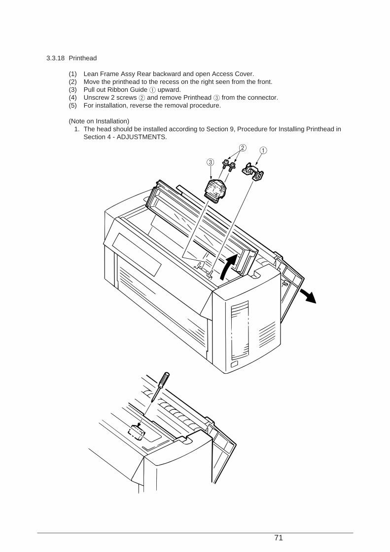
3.3.18 Printhead
(1) Lean Frame Assy Rear backward and open Access Cover.(2) Move the printhead to the recess on the right seen from the front.(3) Pull out Ribbon Guide 1 upward.(4) Unscrew 2 screws 2 and remove Printhead 3 from the connector.(5) For installation, reverse the removal procedure.
(Note on Installation) 1. The head should be installed according to Section 9, Procedure for Installing Printhead in
Section 4 - ADJUSTMENTS.
12
3
72
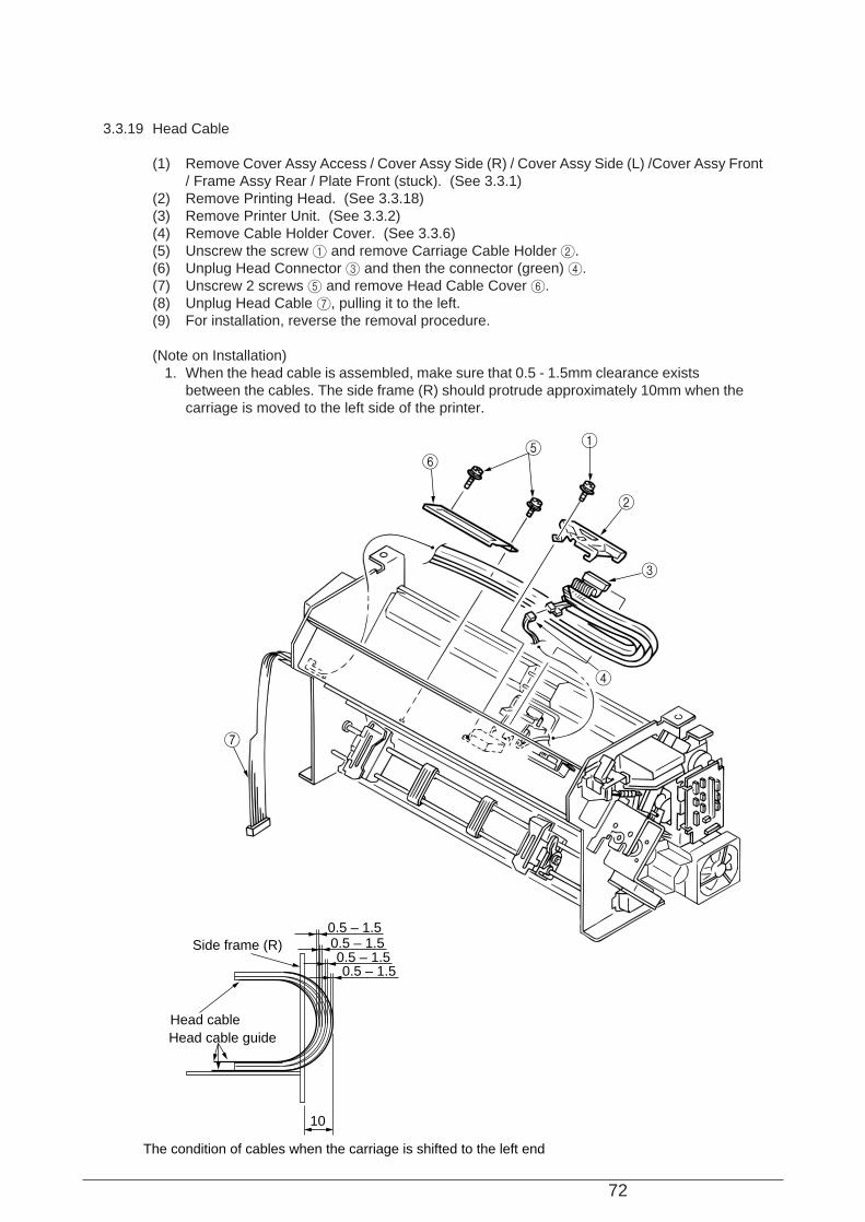
3.3.19 Head Cable
(1) Remove Cover Assy Access / Cover Assy Side (R) / Cover Assy Side (L) /Cover Assy Front/ Frame Assy Rear / Plate Front (stuck). (See 3.3.1)
(2) Remove Printing Head. (See 3.3.18)(3) Remove Printer Unit. (See 3.3.2)(4) Remove Cable Holder Cover. (See 3.3.6)(5) Unscrew the screw 1 and remove Carriage Cable Holder 2.(6) Unplug Head Connector 3 and then the connector (green) 4.(7) Unscrew 2 screws 5 and remove Head Cable Cover 6.(8) Unplug Head Cable 7, pulling it to the left.(9) For installation, reverse the removal procedure.
(Note on Installation) 1. When the head cable is assembled, make sure that 0.5 - 1.5mm clearance exists
between the cables. The side frame (R) should protrude approximately 10mm when the carriage is moved to the left side of the printer.
1
2
3
56
4
7
0.5 – 1.50.5 – 1.50.5 – 1.50.5 – 1.5
10
Side frame (R)
Head cableHead cable guide
The condition of cables when the carriage is shifted to the left end
73
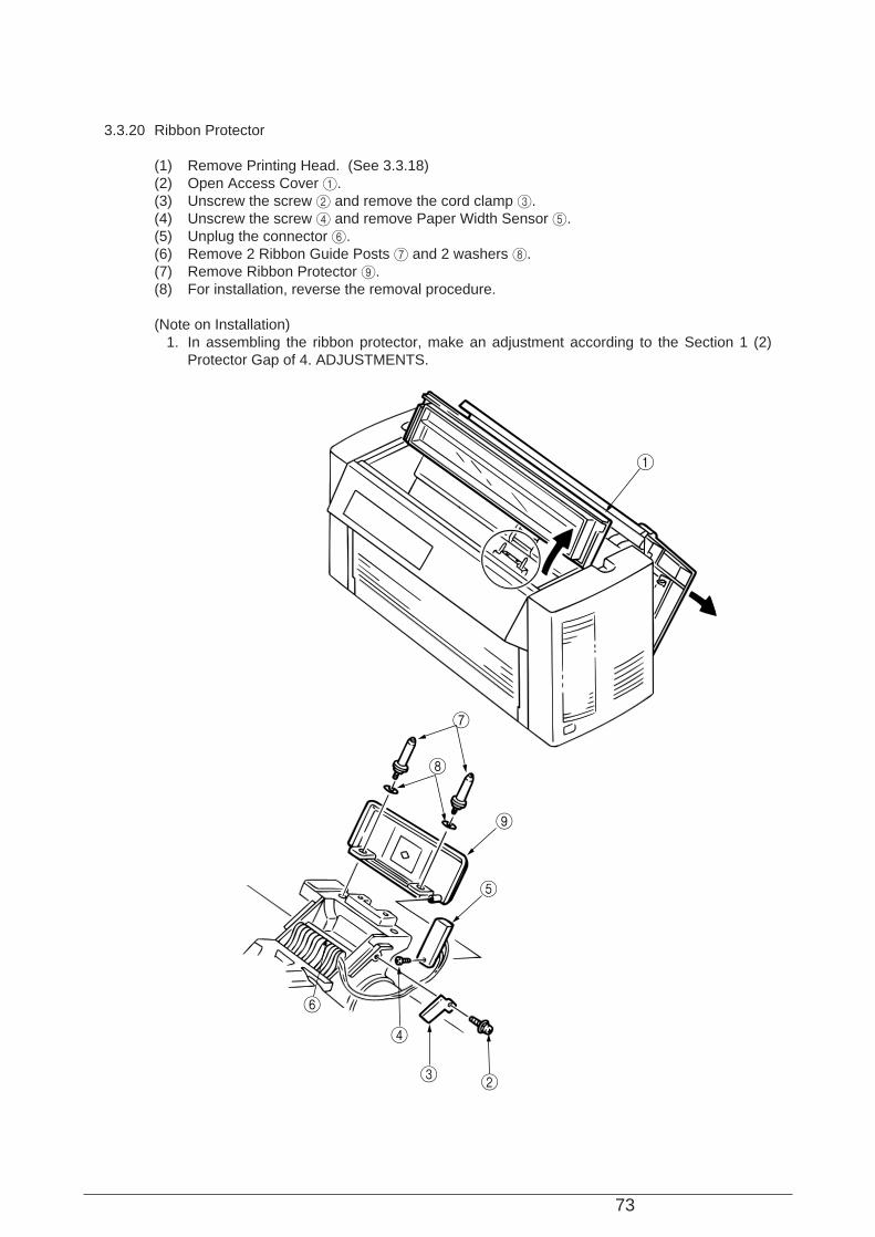
3.3.20 Ribbon Protector
(1) Remove Printing Head. (See 3.3.18)(2) Open Access Cover 1.(3) Unscrew the screw 2 and remove the cord clamp 3.(4) Unscrew the screw 4 and remove Paper Width Sensor 5.(5) Unplug the connector 6.(6) Remove 2 Ribbon Guide Posts 7 and 2 washers 8.(7) Remove Ribbon Protector 9.(8) For installation, reverse the removal procedure.
(Note on Installation) 1. In assembling the ribbon protector, make an adjustment according to the Section 1 (2)
Protector Gap of 4. ADJUSTMENTS.
1
7
8
9
5
6
4
3 2
74
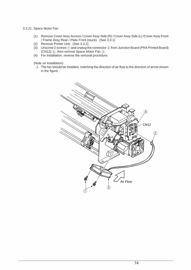
3.3.21 Space Motor Fan
(1) Remove Cover Assy Access / Cover Assy Side (R) / Cover Assy Side (L) /Cover Assy Front/ Frame Assy Rear / Plate Front (stuck). (See 3.3.1)
(2) Remove Printer Unit. (See 3.3.2)(3) Unscrew 2 screws 1 and unplug the connector 2 from Junction Board (PRA Printed Board)
(CN12) 4, then remove Space Motor Fan 3.(4) For installation, reverse the removal procedure.
(Note on Installation) 1. The fan should be installed, matching the direction of air flow to the direction of arrow shown
in the figure.
13
2
4
CN12
Air Flow
75
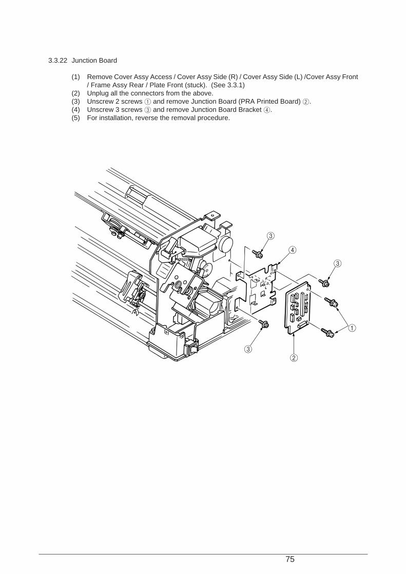
3.3.22 Junction Board
(1) Remove Cover Assy Access / Cover Assy Side (R) / Cover Assy Side (L) /Cover Assy Front/ Frame Assy Rear / Plate Front (stuck). (See 3.3.1)
(2) Unplug all the connectors from the above.(3) Unscrew 2 screws 1 and remove Junction Board (PRA Printed Board) 2.(4) Unscrew 3 screws 3 and remove Junction Board Bracket 4.(5) For installation, reverse the removal procedure.
1
4
3
32
3
76
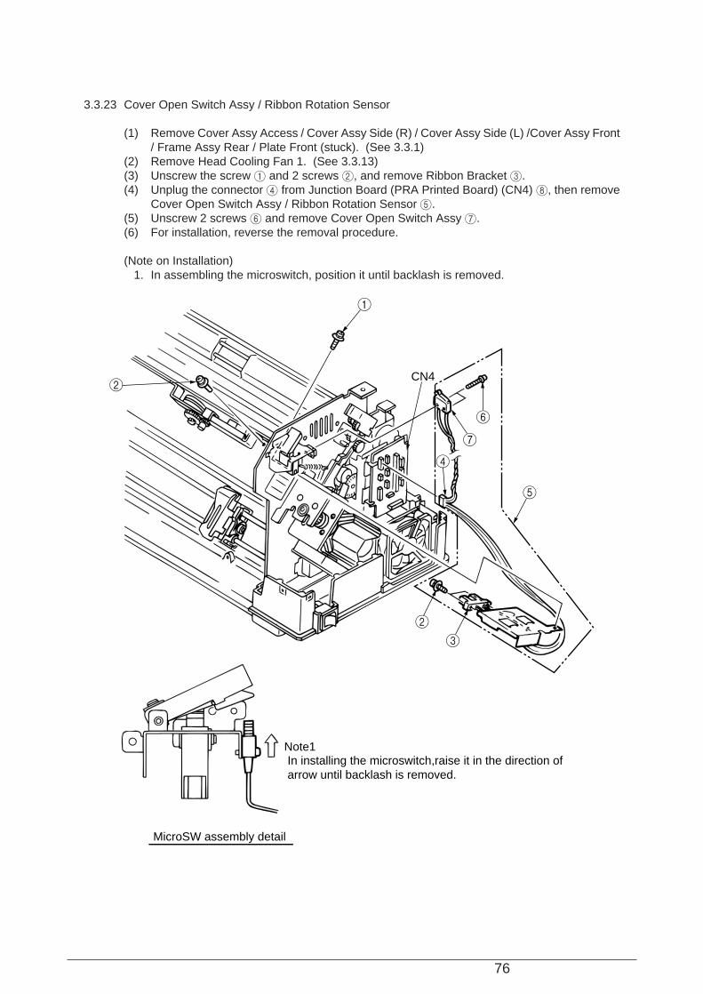
3.3.23 Cover Open Switch Assy / Ribbon Rotation Sensor
(1) Remove Cover Assy Access / Cover Assy Side (R) / Cover Assy Side (L) /Cover Assy Front/ Frame Assy Rear / Plate Front (stuck). (See 3.3.1)
(2) Remove Head Cooling Fan 1. (See 3.3.13)(3) Unscrew the screw 1 and 2 screws 2, and remove Ribbon Bracket 3.(4) Unplug the connector 4 from Junction Board (PRA Printed Board) (CN4) 8, then remove
Cover Open Switch Assy / Ribbon Rotation Sensor 5.(5) Unscrew 2 screws 6 and remove Cover Open Switch Assy 7.(6) For installation, reverse the removal procedure.
(Note on Installation) 1. In assembling the microswitch, position it until backlash is removed.
1
2
2
3
4
5
6
7
CN4
Note1In installing the microswitch,raise it in the direction of arrow until backlash is removed.
MicroSW assembly detail

77
3.3.24 Interlock Switch / Interlock Switch Cord Assy
(1) Remove Cover Assy Access / Cover Assy Side (R) / Cover Assy Side (L) /Cover Assy Front/ Frame Assy Rear / Plate Front (stuck). (See 3.3.1)
(2) Unplug 4 cables 1.(3) Unscrew 2 screws 2 and remove Interlock Switch 3.(4) Unplug 6 connectors 8.(5) Unplug connectors 4 to Spacing motor code 5.(6) Unplug Interlock Switch Cord Assy 7 from the cable clamp.(7) For installation, reverse the removal procedure.
1
7
4
5
8
2
3
Orange(short cord)Yellow(short cord)
Yellow(long cord)Orange(long cord)
Detail drawing
OFF
BrackBlew
GreenRed
Wiring of interlok swith
78
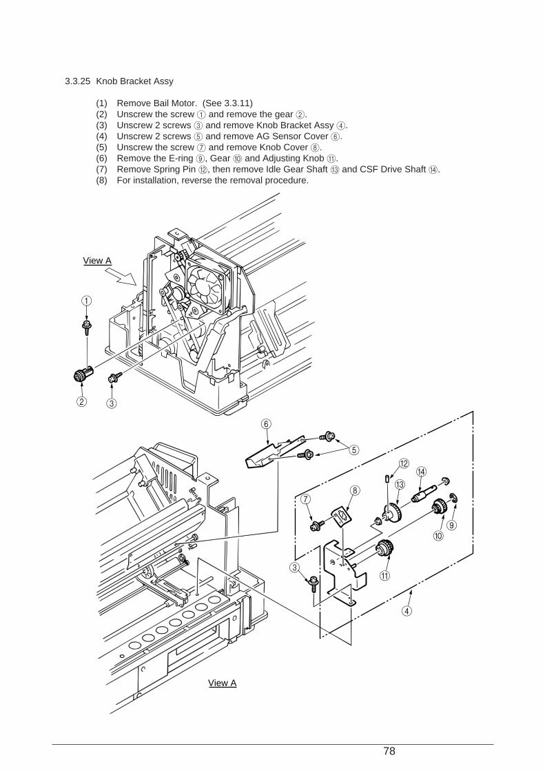
3.3.25 Knob Bracket Assy
(1) Remove Bail Motor. (See 3.3.11)(2) Unscrew the screw 1 and remove the gear 2.(3) Unscrew 2 screws 3 and remove Knob Bracket Assy 4.(4) Unscrew 2 screws 5 and remove AG Sensor Cover 6.(5) Unscrew the screw 7 and remove Knob Cover 8.(6) Remove the E-ring 9, Gear 0 and Adjusting Knob A.(7) Remove Spring Pin B, then remove Idle Gear Shaft C and CSF Drive Shaft D.(8) For installation, reverse the removal procedure.
1
2 3
View A
View A
6
5
78
3
4
A
09
B
CD
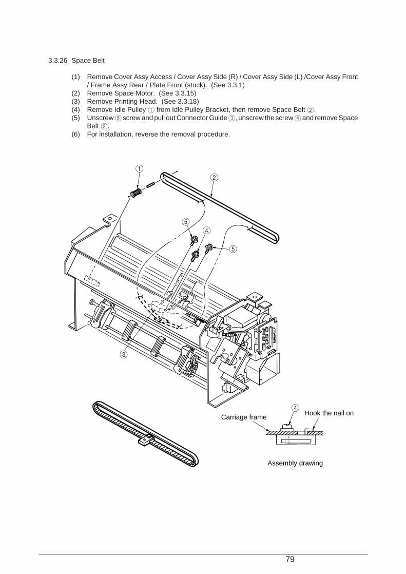
79
3.3.26 Space Belt
(1) Remove Cover Assy Access / Cover Assy Side (R) / Cover Assy Side (L) /Cover Assy Front/ Frame Assy Rear / Plate Front (stuck). (See 3.3.1)
(2) Remove Space Motor. (See 3.3.15)(3) Remove Printing Head. (See 3.3.18)(4) Remove Idle Pulley 1 from Idle Pulley Bracket, then remove Space Belt 2.(5) Unscrew 5 screw and pull out Connector Guide 3, unscrew the screw 4 and remove Space
Belt 2.(6) For installation, reverse the removal procedure.
12
4
4
5
5
3
Carriage frameHook the nail on
Assembly drawing
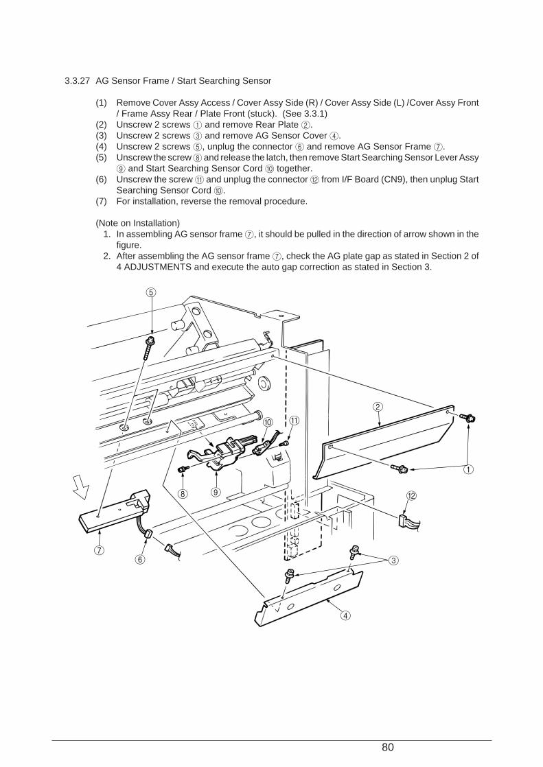
80
3.3.27 AG Sensor Frame / Start Searching Sensor
(1) Remove Cover Assy Access / Cover Assy Side (R) / Cover Assy Side (L) /Cover Assy Front/ Frame Assy Rear / Plate Front (stuck). (See 3.3.1)
(2) Unscrew 2 screws 1 and remove Rear Plate 2.(3) Unscrew 2 screws 3 and remove AG Sensor Cover 4.(4) Unscrew 2 screws 5, unplug the connector 6 and remove AG Sensor Frame 7.(5) Unscrew the screw 8 and release the latch, then remove Start Searching Sensor Lever Assy
9 and Start Searching Sensor Cord 0 together.(6) Unscrew the screw A and unplug the connector B from I/F Board (CN9), then unplug Start
Searching Sensor Cord 0.(7) For installation, reverse the removal procedure.
(Note on Installation) 1. In assembling AG sensor frame 7, it should be pulled in the direction of arrow shown in the
figure. 2. After assembling the AG sensor frame 7, check the AG plate gap as stated in Section 2 of
4 ADJUSTMENTS and execute the auto gap correction as stated in Section 3.
4
3
B
1
2
A0
98
67
5
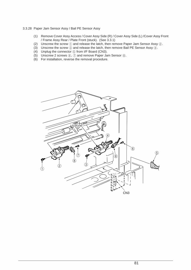
81
3.3.28 Paper Jam Sensor Assy / Bail PE Sensor Assy
(1) Remove Cover Assy Access / Cover Assy Side (R) / Cover Assy Side (L) /Cover Assy Front/ Frame Assy Rear / Plate Front (stuck). (See 3.3.1)
(2) Unscrew the screw 1 and release the latch, then remove Paper Jam Sensor Assy 2.(3) Unscrew the screw 3 and release the latch, then remove Bail PE Sensor Assy 4.(4) Unplug the connector 5 from I/F Board (CN3).(5) Unscrew 2 screws 6, 7 and remove Paper Jam Sensor 8.(6) For installation, reverse the removal procedure.
56
8
4
3
7
8
21
CN3

82
3.3.29 Sprocket Assy (L) (R) (Front Tractor)
(1) Remove Cover Assy Access / Cover Assy Side (R) / Cover Assy Side (L) /Cover Assy Front/ Frame Assy Rear / Plate Front (stuck). (See 3.3.1)
(2) Remove Printer Unit. (See 3.3.2)(3) Remove Space Motor Fans. (See 3.3.21)(4) Remove 2 Sheet Guides 1.(5) Unplug the connector 3 from I/F Board (PHA Printed Board) (CN5) 2.(6) Release cords at cord clamps and remove the Snap Band.(7) Release the claw to remove Front Tractor Drive Gear 4.(8) Pull out Front Tractor Drive Shaft 5 to the right.(9) Unscrew 2 screws 6 and remove Front Lock Shaft 7, Sprocket Assys (L) 8 and (R) 9
together.(10) Release Lock Lever 0 and pull out Sprocket Assys (L) 8 and (R) 9 from Front Lock Shaft
7.(11) For installation, reverse the removal procedure.
(Note on Installation) 1. Adjust sprocket pin phases of Sprocket Assys (L) 8 and (R) 9, before inserting Front Tractor
Drive Shaft 5 into them.
4
3
2
6
5
6
7
0
9
1
8
CN5
Claw
Wave
Eling
WasherBush
Drive shaft
R Side View
83
3.3.30 Sheet Feeder Assy (L) Rear / Sheet Feeder Assy (R) Rear
(1) Remove Cover Assy Access / Cover Assy Side (R) / Cover Assy Side (L) /Cover Assy Front/ Frame Assy Rear / Plate Front (stuck). (See 3.3.1)
(2) Remove Printer Unit. (See 3.3.2)(3) Remove PG Cooling Fan. (See 3.3.5)(4) Remove Mini Pitch Belt. (See 3.3.9)(5) Remove I/F Board (PHA Printed Board). (See 3.3.6)(6) Remove Center Guide Lower 1.(7) Open the clamp of Drive Gear 2 to the arrow direction and remove the gear, then pull out Rear
Tractor Drive Shaft 3.(8) Open the clamp of Rear Tractor Drive Gear 4 to the arrow direction and remove the gear,
then pull out Rear Tractor Drive Shaft 5. At this time, Center Guide Upper 6 and FrictionPiece 7 come off together.
(9) Remove 2 Snap Bands 0 fastening Micro Switch Connecting Cord 9 on Sheet Feeder Assy(L) Rear 8, from Main Frame Assy A. Then release the cords from the clamps on the cordroute.
(10) Unscrew 2 screws B on the right and left then remove Lock Shaft D with Sheet Feeder Assy(L) Rear 8 and Sheet Feeder Assy Rear (R) C on.
(11) Release Lock Lever E and remove Sheet Feeder Assy (L) Rear 8 and Sheet Feeder AssyRear (R) C from Lock Shaft D.
(12) For installation, reverse the removal procedure.
(Note on Installation) 1. Mount Sheet Feeder Assy (L) Rear 8 between 2 protrusions B on Main Frame Assy A. 2. Mount Rear Tractor Drive Shafts 3 and 5 as follows:
(a) Adjust the position of Sprocket Wheel D protrusion at right and left pin tractors to thatof Rear Tractor Drive Gear 4 hole, then insert Rear Tractor Drive Shaft 5.
(b) Adjust the position of Pin Wheel F protrusion at right and left pin tractors then insert RearTractor Drive Shaft 3.
(c) Adjust the position of Pin Wheel F protrusion to that of Drive Gear B 2 hole, align theholes at Rear Tractor Drive Gear 4 and at Drive Gear B 2 then mount Drive Gear B2 on Rear Tractor Drive Shaft 3.
3. Give friction to Friction Piece 7 with a screwdriver turned 45 degrees, after inserting it intoRear Tractor Drive Shaft 5.Slow moving of Center Guide Upper 6 to the right/left means the right installation, andsmooth one means the false installation.
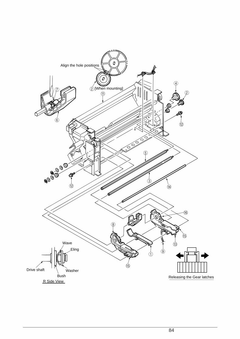
84
2A
6
7
4
2
B
5
8
3
D
1
E
E
F
9
C
B
Align the hole positions
[When mounting]
Releasing the Gear latches
Wave
Eling
WasherBush
Drive shaft
R Side View

85
1. Matching the phase of pin tractors a. Match the direction of pin wheel projections on right/left pin tractor to that of mark on the 2 (rear
tractor drive gear)b. Match the direction of wheel projections on right/left pin tractor to that of mark on 4 (drive gearB), and
install 2(drive gear B) to 5 3 (rear drive shaft of the rear tractor Assy) at a position where the directions of marks on 4 (drive gear B) and 2 (rear tractor drive gear) match.
8 Assembling friction piece
Open up the notch to 1mm and assemble it, positioning the notch as shown in figure.
Notch is rotated by 45°
Rotated notch
45°
Wheel
Pinwheel
Match the direction of projections
Match the position of marks
Rear tracor Assy Gears phase drawing4
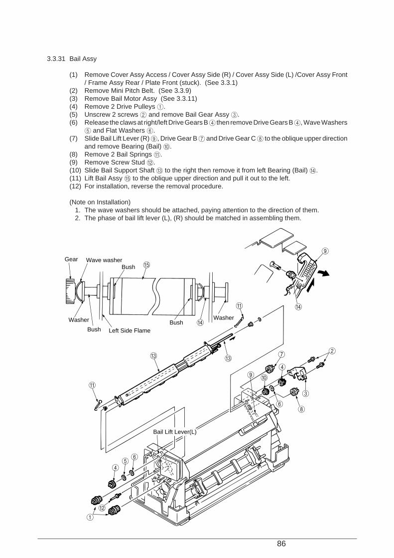
86
3.3.31 Bail Assy
(1) Remove Cover Assy Access / Cover Assy Side (R) / Cover Assy Side (L) /Cover Assy Front/ Frame Assy Rear / Plate Front (stuck). (See 3.3.1)
(2) Remove Mini Pitch Belt. (See 3.3.9)(3) Remove Bail Motor Assy (See 3.3.11)(4) Remove 2 Drive Pulleys 1.(5) Unscrew 2 screws 2 and remove Bail Gear Assy 3.(6) Release the claws at right/left Drive Gears B 4 then remove Drive Gears B 4, Wave Washers
5 and Flat Washers 6.(7) Slide Bail Lift Lever (R) 9, Drive Gear B 7 and Drive Gear C 8 to the oblique upper direction
and remove Bearing (Bail) 0.(8) Remove 2 Bail Springs A.(9) Remove Screw Stud B.(10) Slide Bail Support Shaft C to the right then remove it from left Bearing (Bail) D.(11) Lift Bail Assy E to the oblique upper direction and pull it out to the left.(12) For installation, reverse the removal procedure.
(Note on Installation) 1. The wave washers should be attached, paying attention to the direction of them. 2. The phase of bail lift lever (L), (R) should be matched in assembling them.
CC
A
A
2
3
8
4
7
09
65
4
B
1
6
9
D
E
D
Gear Wave washerBush
Washer
Bush Left Side FlameBush
Washer
Bail Lift Lever(L)
87
4. ADJUSTMENTS
(1) Be sure to carry out this adjustment with the printer mechanism mounted on the lower cover.
(2) Be sure to carry out this adjustment operation on a level and highly rigid work table (flatness:less than 0.039 inch or 1 mm) so as to minimize adjustment error.
[Service Tool]• No. 2-200 Philips screwdriver• No. 2-200 screwdriver• Feeler gauge• 500 g rod tension gauge• Calipers
Adjustment should be conducted after removing the Rear Cover (B) and setting the Dip Switch 1on the board to “ON”(maintenance mode). (See Note 1 and 2)
Note 1: After the adjustment and lubrication have completed, set the all the dip switches to“OFF”(normal operation mode), and fix the Rear Cover (B) with the mounting screws.
Note 2: The local test printing except for the menu printing should be implemented with all the dipswitches set to “OFF”(normal operation mode).
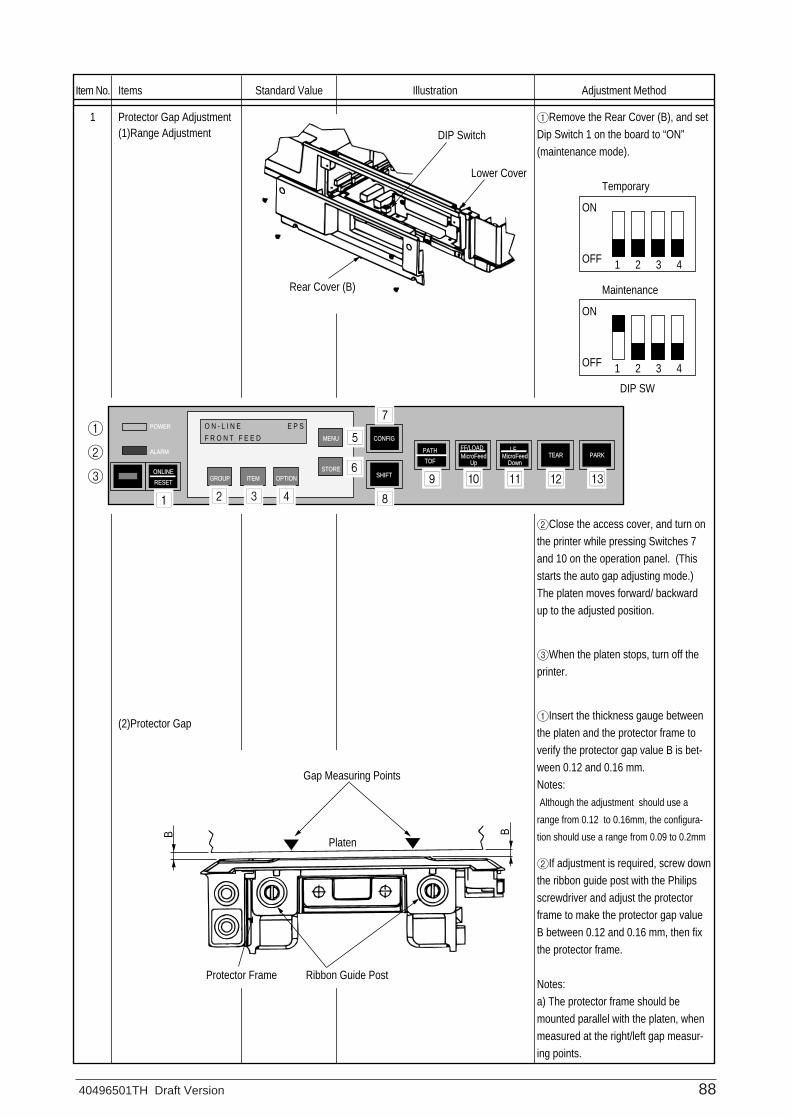
40496501TH Draft Version 88
Item No.
1
Items
Protector Gap Adjustment(1)Range Adjustment
(2)Protector Gap
Standard Value Illustration Adjustment Method
1Remove the Rear Cover (B), and set Dip Switch 1 on the board to “ON” (maintenance mode).
2Close the access cover, and turn on the printer while pressing Switches 7 and 10 on the operation panel. (This starts the auto gap adjusting mode.) The platen moves forward/ backward up to the adjusted position.
3When the platen stops, turn off the printer.
1Insert the thickness gauge between the platen and the protector frame to verify the protector gap value B is bet-ween 0.12 and 0.16 mm.Notes: Although the adjustment should use a
range from 0.12 to 0.16mm, the configura-
tion should use a range from 0.09 to 0.2mm
2If adjustment is required, screw down the ribbon guide post with the Philips screwdriver and adjust the protector frame to make the protector gap value B between 0.12 and 0.16 mm, then fix the protector frame.
Notes:a) The protector frame should be mounted parallel with the platen, when measured at the right/left gap measur-ing points.
DIP Switch
Lower Cover
Rear Cover (B)
ON
OFF 1 2 3 4
ON
OFF 1 2 3 4
DIP SW
Temporary
Maintenance
PARKTEARPATH
ONLINE
RESETGROUP
POWER
ALARM
ITEM OPTION
MENU
STORETOF
SHIFT
O N - L I N E E P S
F R O N T F E E D CONFIG
LFMicroFeed
Down
FF/LOADMicroFeed
Up
1 2 3 4
5
6
7
8
9 0 A B C
1
2
3
Gap Measuring Points
Ribbon Guide PostProtector Frame
Platen
BB
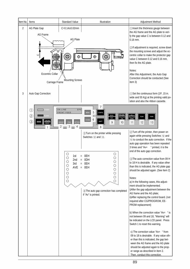
89
Item No.
2
3
Items
AG Plate Gap
Auto Gap Correction
Standard Value
C=0.14±0.02mm
Illustration
3Turn on the printer while pressing Switches B and C.
4The auto gap correction has completed if “Av” is printed.
Adjustment Method
1Insert the thickness gauge between the AG frame and the AG plate to veri-fy the gap value C is between 0.12 and 0.16 mm.
2If adjustment is required, screw down the mounting screws and adjust the ec-centric collar to make the protector gap value C between 0.12 and 0.16 mm, then fix the AG plate.
Notes:After this Adjustment, the Auto Gap Correction should be conducted (See item 3)
1Set the continuous form (1P, 15 in. wide and 55 Kg) at the printing valid po-sition and also the ribbon cassette.
2Turn off the printer, then power on again while pressing Switches B and C to conduct the auto correction. If the auto gap operation has been repeated 3 times and “Av= “ printed, it is the end of the auto gap correction.
3The auto correction value from 09 H to 18 H is desirable. If any value other than this is indicated, the AG plate gap should be adjusted again. (See Item 2)
Notes:a) In the following cases, this adjust-ment should be implemented.i)After the gap adjustment between the AG frame and the AG plate;ii)After replacing the control board. (not required after CG/PROGROM, EE-PROM replacement)
b) When the correction value “Av= “ is not between 09 and 18, “Warning” will be indicated on the LCD panel. Press Switch 1 to reset this warning.
c) The correction value “Av= “ from 09 to 18 is desirable. If any value oth-er than this is indicated, the gap bet-ween the AG frame and the AG plate should be adjusted again to the prop-er range as described in Item 2. Then, conduct this correction.
CAG Frame
AG Plate
Eccentric Collar
Carriage FrameMounting Screws
PARKTEARPATH
ONLINE
RESETGROUP
POWER
ALARM
ITEM OPTION
MENU
STORETOF
SHIFT
O N - L I N E E P S
F R O N T F E E D CONFIG
LFMicroFeed
Down
FF/LOADMicroFeed
Up
1 2 3 4
5
6
7
8
9 0 A B C
1
2
3
1st = 0EH2nd = 0DH3rd = 0EHAVE = 0EH
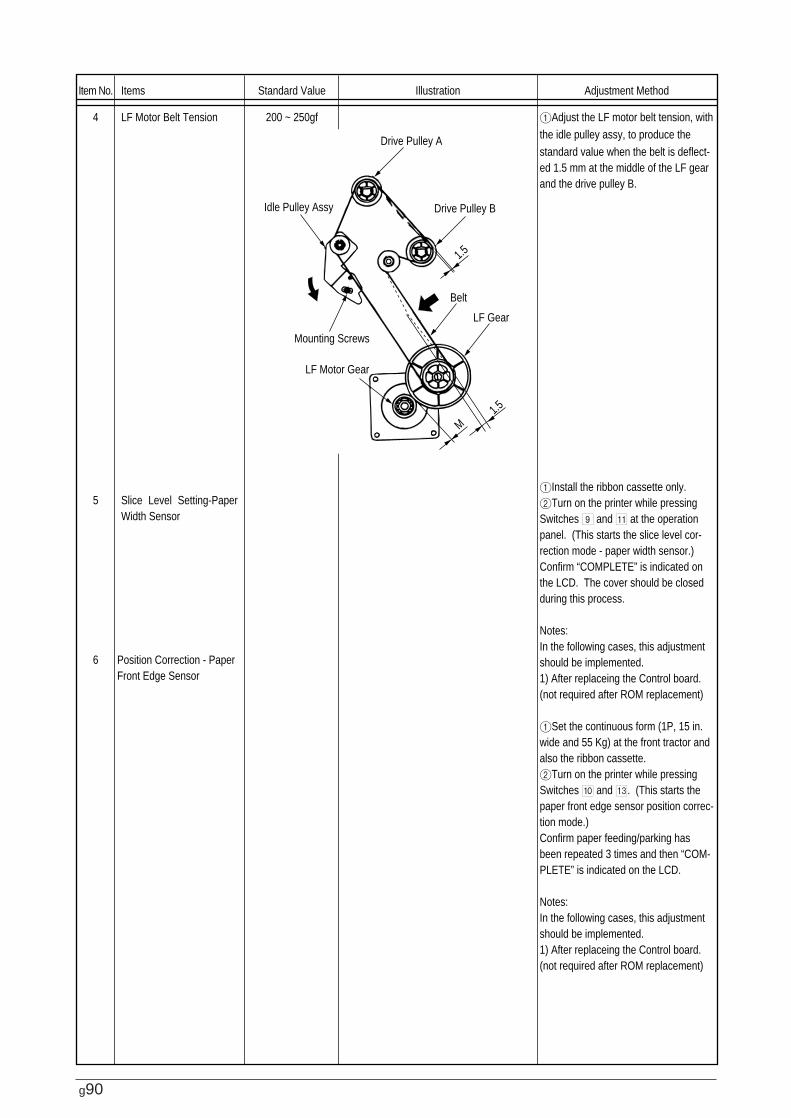
g90
Item No.
4
5
6
Items
LF Motor Belt Tension
Slice Level Setting-Paper Width Sensor
Position Correction - Paper Front Edge Sensor
Standard Value
200 ~ 250gf
Illustration Adjustment Method
1Adjust the LF motor belt tension, with the idle pulley assy, to produce the standard value when the belt is deflect-ed 1.5 mm at the middle of the LF gear and the drive pulley B.
1Install the ribbon cassette only.2Turn on the printer while pressing Switches 9 and A at the operation panel. (This starts the slice level cor-rection mode - paper width sensor.)Confirm “COMPLETE” is indicated on the LCD. The cover should be closed during this process.
Notes:In the following cases, this adjustment should be implemented.1) After replaceing the Control board. (not required after ROM replacement)
1Set the continuous form (1P, 15 in. wide and 55 Kg) at the front tractor and also the ribbon cassette.2Turn on the printer while pressing Switches 0 and C. (This starts the paper front edge sensor position correc-tion mode.)Confirm paper feeding/parking has been repeated 3 times and then “COM-PLETE” is indicated on the LCD.
Notes:In the following cases, this adjustment should be implemented.1) After replaceing the Control board. (not required after ROM replacement)
Idle Pulley Assy
Drive Pulley A
Drive Pulley B
Belt
LF Gear
Mounting Screws
LF Motor Gear
1.5
1.5
M
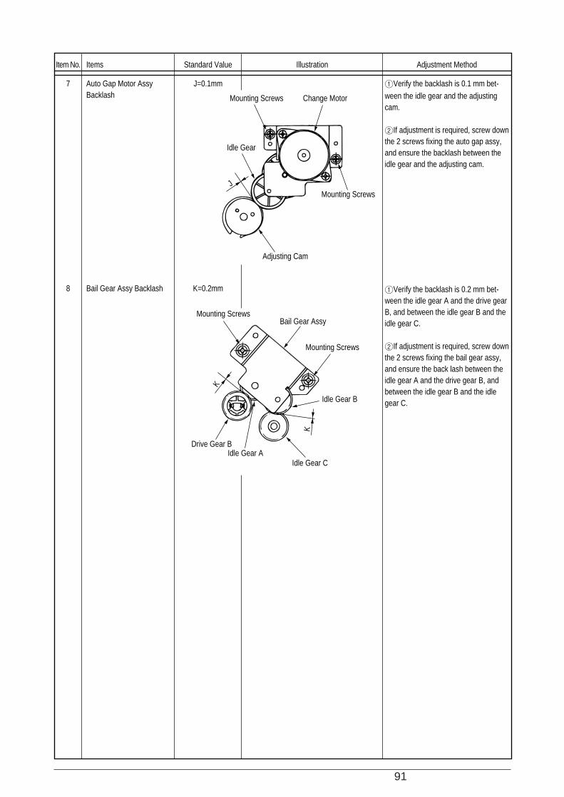
91
Item No.
7
8
Items
Auto Gap Motor Assy Backlash
Bail Gear Assy Backlash
Standard Value
J=0.1mm
K=0.2mm
Illustration Adjustment Method
1Verify the backlash is 0.1 mm bet-ween the idle gear and the adjusting cam.
2If adjustment is required, screw down the 2 screws fixing the auto gap assy, and ensure the backlash between the idle gear and the adjusting cam.
1Verify the backlash is 0.2 mm bet-ween the idle gear A and the drive gear B, and between the idle gear B and the idle gear C.
2If adjustment is required, screw down the 2 screws fixing the bail gear assy, and ensure the back lash between the idle gear A and the drive gear B, and between the idle gear B and the idle gear C.
Mounting Screws
Mounting Screws
Mounting Screws
Mounting Screws
Bail Gear Assy
Idle Gear B
Idle Gear CIdle Gear A
Drive Gear B
Adjusting Cam
Change Motor
Idle Gear
J
K
K
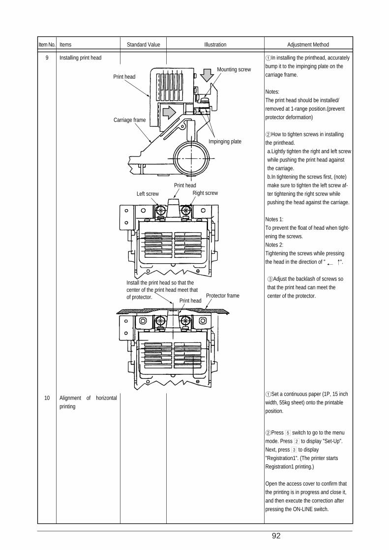
92
Item No.
9
10
Items
Installing print head
Alignment of horizontal printing
Standard Value Illustration Adjustment Method
1In installing the printhead, accurately bump it to the impinging plate on the carriage frame.
Notes:The print head should be installed/ removed at 1-range position.(prevent protector deformation)
2How to tighten screws in installing the printhead.a.Lightly tighten the right and left screw while pushing the print head against the carriage.b.In tightening the screws first, (note) make sure to tighten the left screw af-ter tightening the right screw while pushing the head against the carriage.
Notes 1:To prevent the float of head when tight-ening the screws.Notes 2:Tightening the screws while pressing the head in the direction of " ".
3Adjust the backlash of screws so that the print head can meet the center of the protector.
1Set a continuous paper (1P, 15 inch width, 55kg sheet) onto the printable position.
2Press 5 switch to go to the menu mode. Press 2 to display "Set-Up". Next, press 3 to display "Registration1". (The printer starts Registration1 printing.)
Open the access cover to confirm that the printing is in progress and close it, and then execute the correction after pressing the ON-LINE switch.
Print head
Carriage frame
Impinging plate
Print headLeft screw Right screw
Mounting screw
Print head
Install the print head so that the center of the print head meet that of protector. Protector frame
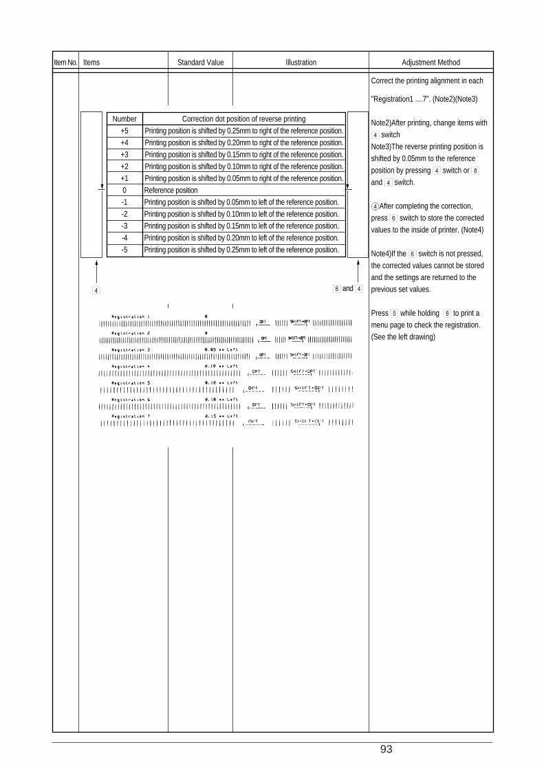
93
Item No. Items Standard Value Illustration Adjustment Method
Correct the printing alignment in each
"Registration1 ....7". (Note2)(Note3)
Note2)After printing, change items with 4 switchNote3)The reverse printing position is shifted by 0.05mm to the reference position by pressing 4 switch or 8 and 4 switch.
4After completing the correction, press 6 switch to store the corrected values to the inside of printer. (Note4)
Note4)If the 6 switch is not pressed, the corrected values cannot be stored and the settings are returned to the previous set values.
Press 5 while holding 8 to print a menu page to check the registration. (See the left drawing)
Number+5+4+3+2+10-1-2-3-4-5
Correction dot position of reverse printingPrinting position is shifted by 0.25mm to right of the reference position.Printing position is shifted by 0.20mm to right of the reference position.Printing position is shifted by 0.15mm to right of the reference position.Printing position is shifted by 0.10mm to right of the reference position.Printing position is shifted by 0.05mm to right of the reference position.Reference positionPrinting position is shifted by 0.05mm to left of the reference position.Printing position is shifted by 0.10mm to left of the reference position.Printing position is shifted by 0.15mm to left of the reference position.Printing position is shifted by 0.20mm to left of the reference position.Printing position is shifted by 0.25mm to left of the reference position.
4 8 and 4
94
5. CLEANIG AND LUBRICATION
5.1 Cleaning
[Caution]
1. Be sure to turn OFF the AC POWER switch before cleaning. Remove the AC Power cord fromthe printer.
2. Avoid dust inside the printer mechanism when cleaning.
3. If a lubricated part has been cleaned, be sure to apply lubricating oil to that portion aftercleaning.
(1) Cleaning time
When the equipment time has reached six months or 300 hours, whichever comes first.
(2) Cleaning tools
Dry cloth (soft cloth such as gauze), vacuum cleaner.
(3) Places to be cleaned
Table 5.1 lists the places to be cleaned:
Table 5.1
Place to be cleaned
Main shaft and the vicinity
Paper travel surface
Ribbon guide and the vicinity
Cleaning procedure
Remove paper waste and wipe off
stain, dust, waste. etc.
95
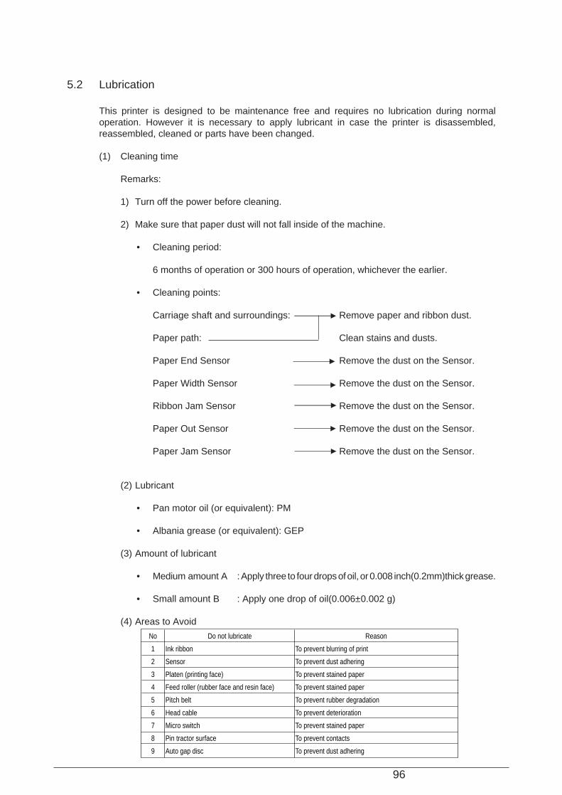
96
5.2 Lubrication
This printer is designed to be maintenance free and requires no lubrication during normaloperation. However it is necessary to apply lubricant in case the printer is disassembled,reassembled, cleaned or parts have been changed.
(1) Cleaning time
Remarks:
1) Turn off the power before cleaning.
2) Make sure that paper dust will not fall inside of the machine.
• Cleaning period:
6 months of operation or 300 hours of operation, whichever the earlier.
• Cleaning points:
Carriage shaft and surroundings: Remove paper and ribbon dust.
Paper path: Clean stains and dusts.
Paper End Sensor Remove the dust on the Sensor.
Paper Width Sensor Remove the dust on the Sensor.
Ribbon Jam Sensor Remove the dust on the Sensor.
Paper Out Sensor Remove the dust on the Sensor.
Paper Jam Sensor Remove the dust on the Sensor.
(2) Lubricant
• Pan motor oil (or equivalent): PM
• Albania grease (or equivalent): GEP
(3) Amount of lubricant
• Medium amount A : Apply three to four drops of oil, or 0.008 inch(0.2mm)thick grease.
• Small amount B : Apply one drop of oil(0.006±0.002 g)
(4) Areas to Avoid
No
1
2
3
4
5
6
7
8
9
Do not lubricate
Ink ribbon
Sensor
Platen (printing face)
Feed roller (rubber face and resin face)
Pitch belt
Head cable
Micro switch
Pin tractor surface
Auto gap disc
Reason
To prevent blurring of print
To prevent dust adhering
To prevent stained paper
To prevent stained paper
To prevent rubber degradation
To prevent deterioration
To prevent stained paper
To prevent contacts
To prevent dust adhering
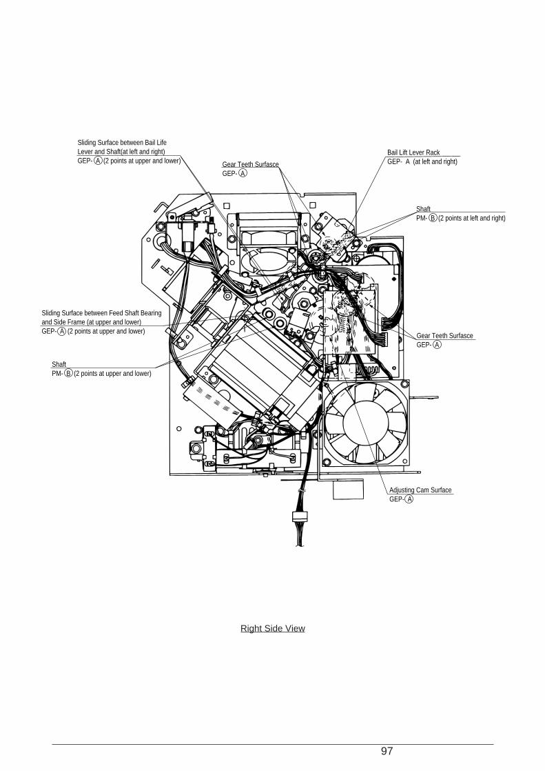
97
Sliding Surface between Bail Life Lever and Shaft(at left and right)GEP- A (2 points at upper and lower) Gear Teeth Surfasce
GEP- A
Gear Teeth SurfasceGEP- A
ShaftPM- B (2 points at left and right)
Bail Lift Lever RackGEP- A (at left and right)
Sliding Surface between Feed Shaft Bearing and Side Frame (at upper and lower)GEP- A (2 points at upper and lower)
ShaftPM- B (2 points at upper and lower)
Adjusting Cam SurfaceGEP- A
Right Side View
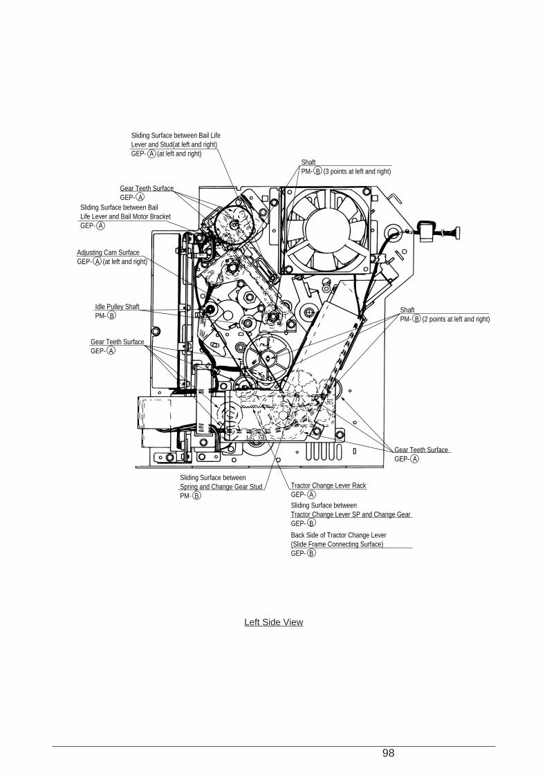
98
Left Side View
Sliding Surface between Bail Life Lever and Stud(at left and right)GEP- A (at left and right)
Sliding Surface between BailLife Lever and Bail Motor BracketGEP- A
Gear Teeth SurfaceGEP- A
Adjusting Cam SurfaceGEP- A (at left and right)
Idle Pulley ShaftPM- B
ShaftPM- B (3 points at left and right)
ShaftPM- B (2 points at left and right)
Gear Teeth SurfaceGEP- A
Gear Teeth SurfaceGEP- A
Sliding Surface between Spring and Change Gear StudPM- B
Sliding Surface between Tractor Change Lever SP and Change GearGEP- B
Back Side of Tractor Change Lever(Slide Frame Connecting Surface)GEP- B
Tractor Change Lever RackGEP- A
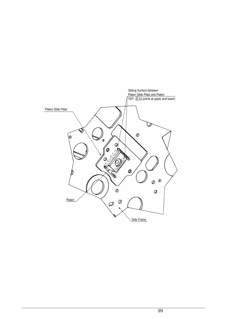
99
Sliding Surface between Platen Slide Plate and PlatenTEP- A (2 points at upper and lower)
Platen Slide Plate
Platen
Side Frame
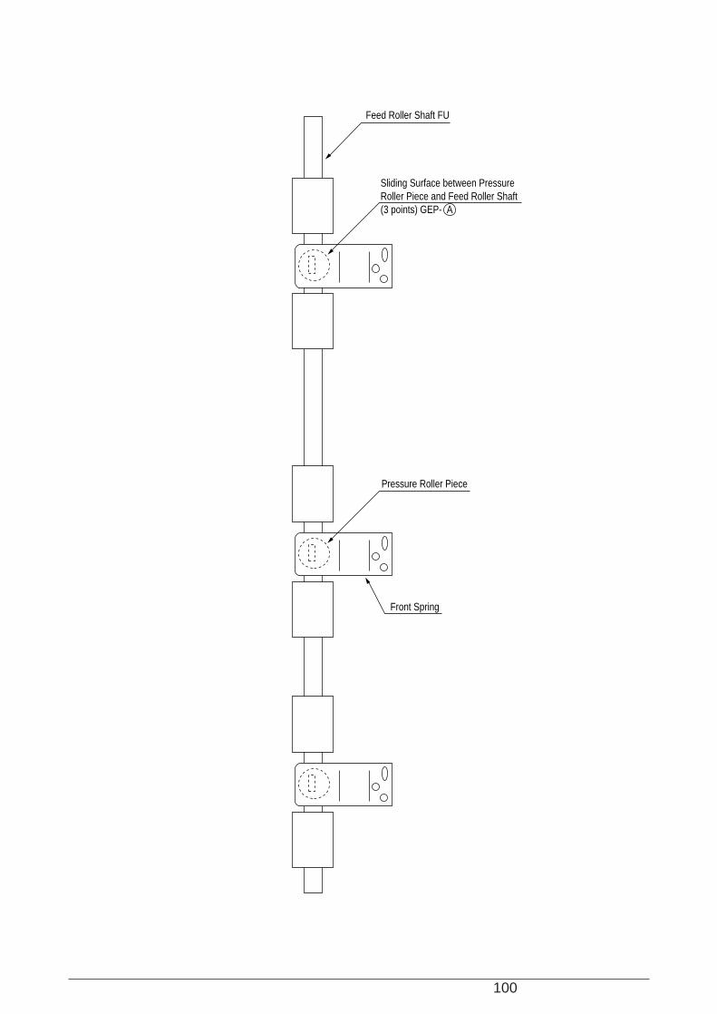
100
Sliding Surface between Pressure Roller Piece and Feed Roller Shaft(3 points) GEP- A
Feed Roller Shaft FU
Pressure Roller Piece
Front Spring
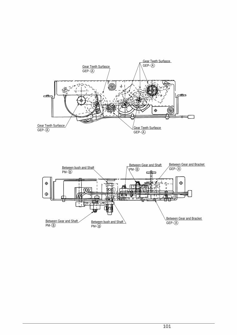
101
Gear Teeth SurfasceGEP- A
Gear Teeth SurfasceGEP- A
Between bush and ShaftPM- B
Between bush and ShaftPM- B
Between Gear and ShaftPM- B
Between Gear and ShaftPM- B
Between Gear and BracketGEP- A
Between Gear and BracketGEP- A
Gear Teeth SurfasceGEP- A
Gear Teeth SurfasceGEP- A
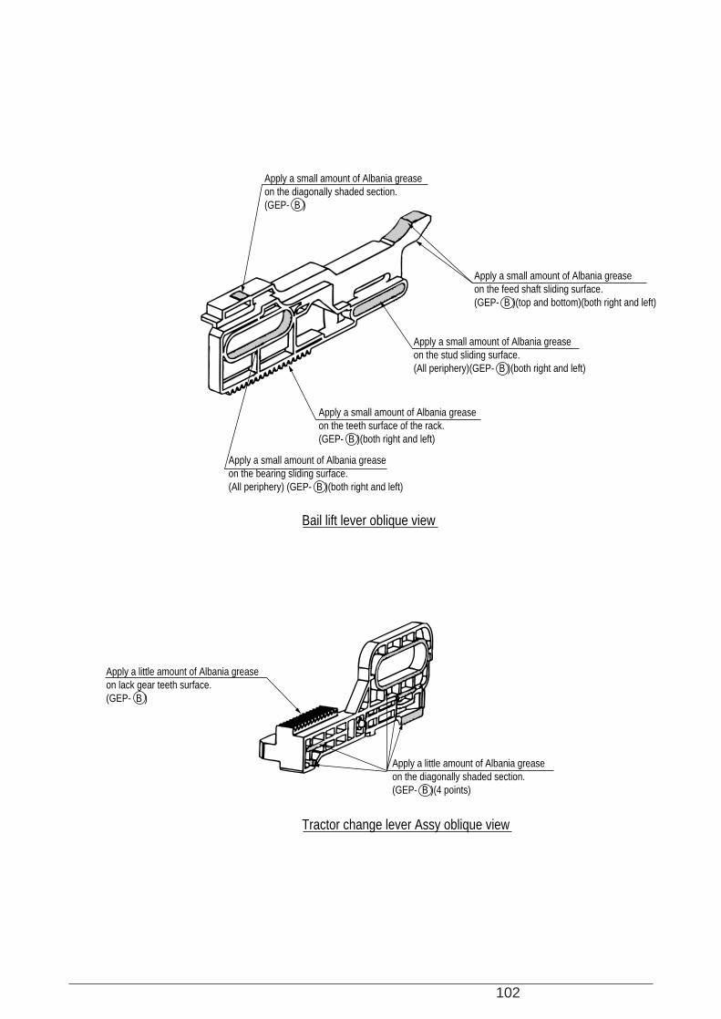
102
Apply a small amount of Albania grease on the bearing sliding surface.(All periphery) (GEP- B )(both right and left)
Apply a little amount of Albania grease on lack gear teeth surface.(GEP- B )
Apply a little amount of Albania grease on the diagonally shaded section.(GEP- B )(4 points)
Apply a small amount of Albania grease on the teeth surface of the rack.(GEP- B )(both right and left)
Apply a small amount of Albania grease on the stud sliding surface.(All periphery)(GEP- B )(both right and left)
Apply a small amount of Albania grease on the diagonally shaded section.(GEP- B )
Apply a small amount of Albania grease on the feed shaft sliding surface.(GEP- B )(top and bottom)(both right and left)
Bail lift lever oblique view
Tractor change lever Assy oblique view
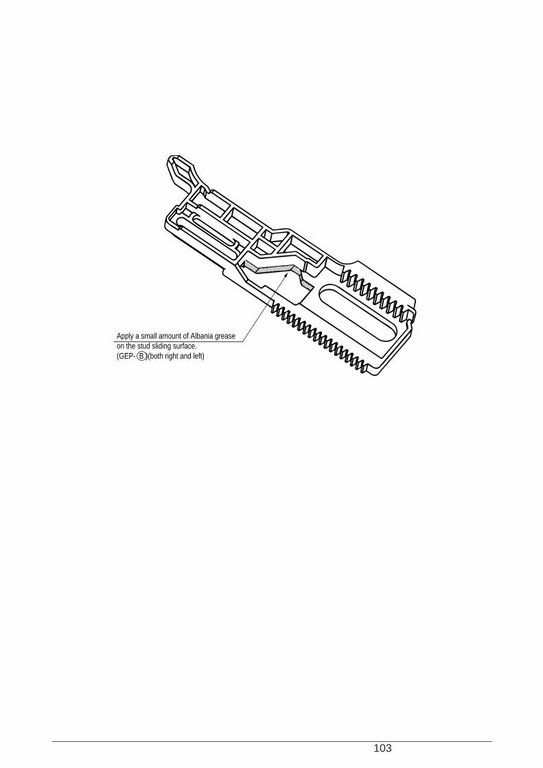
103
Apply a small amount of Albania grease on the stud sliding surface.(GEP- B )(both right and left)
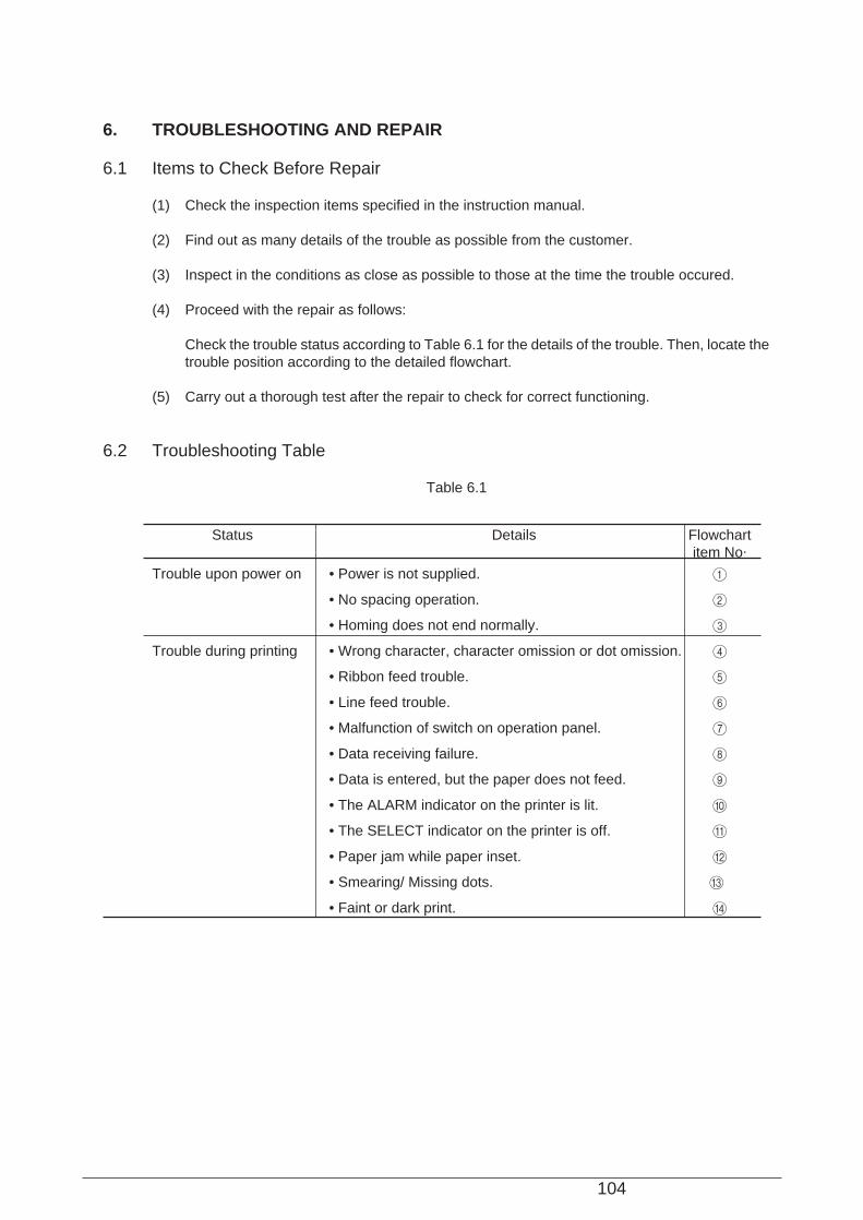
104
6. TROUBLESHOOTING AND REPAIR
6.1 Items to Check Before Repair
(1) Check the inspection items specified in the instruction manual.
(2) Find out as many details of the trouble as possible from the customer.
(3) Inspect in the conditions as close as possible to those at the time the trouble occured.
(4) Proceed with the repair as follows:
Check the trouble status according to Table 6.1 for the details of the trouble. Then, locate thetrouble position according to the detailed flowchart.
(5) Carry out a thorough test after the repair to check for correct functioning.
6.2 Troubleshooting Table
Table 6.1
Status Details Flowchartitem No.
Trouble upon power on • Power is not supplied. 1
• No spacing operation. 2
• Homing does not end normally. 3
Trouble during printing • Wrong character, character omission or dot omission. 4
• Ribbon feed trouble. 5
• Line feed trouble. 6
• Malfunction of switch on operation panel. 7
• Data receiving failure. 8
• Data is entered, but the paper does not feed. 9
• The ALARM indicator on the printer is lit. 0
• The SELECT indicator on the printer is off. A
• Paper jam while paper inset. B
• Smearing/ Missing dots. C
• Faint or dark print. D
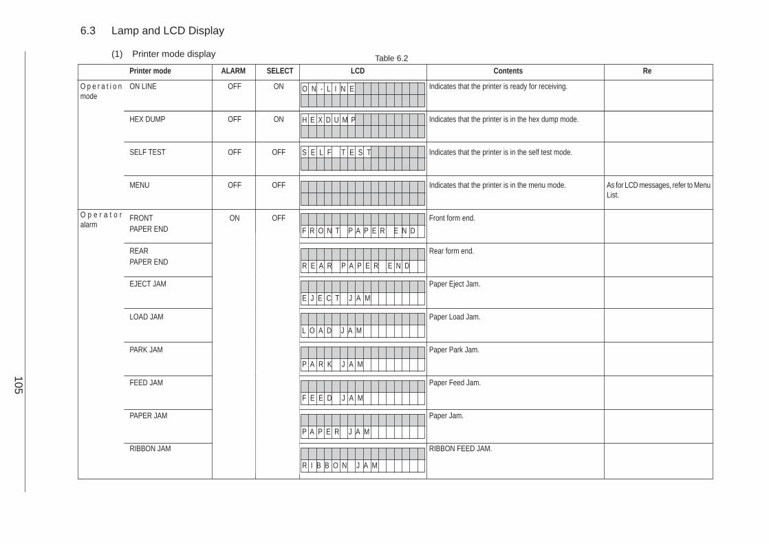
Printer mode ALARM SELECT LCD Contents Re
105
6.3 Lamp and LCD Display
(1) Printer mode display
O p e r a t i o nmode
O p e r a t o ralarm
OFF
OFF
OFF
OFF
ON
As for LCD messages, refer to MenuList.
Indicates that the printer is ready for receiving.
Indicates that the printer is in the hex dump mode.
Indicates that the printer is in the self test mode.
Indicates that the printer is in the menu mode.
Front form end.
Rear form end.
Paper Eject Jam.
Paper Load Jam.
Paper Park Jam.
Paper Feed Jam.
Paper Jam.
RIBBON FEED JAM.
ON LINE
HEX DUMP
SELF TEST
MENU
FRONTPAPER END
REARPAPER END
EJECT JAM
LOAD JAM
PARK JAM
FEED JAM
PAPER JAM
RIBBON JAM
Table 6.2
ON
ON
OFF
OFF
OFF
O N - L I N E
H E X D U M P
S E L F T E S T
F R O N T P A P E R E N D
R E A R P A P E R E N D
E J E C T J A M
L O A D J A M
P A R K J A M
F E E D J A M
P A P E R J A M
R I B B O N J A M
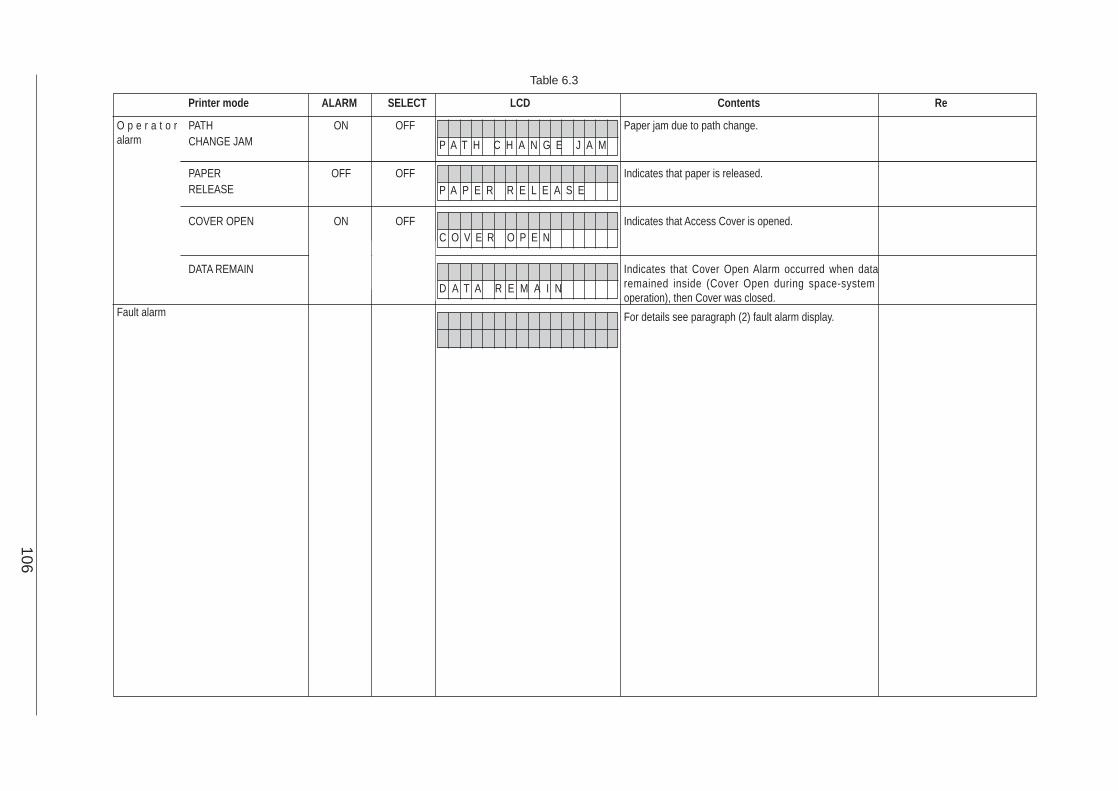
Printer mode ALARM SELECT LCD Contents Re
106
O p e r a t o ralarm
Fault alarm
ON
OFF
ON
Paper jam due to path change.
Indicates that paper is released.
Indicates that Access Cover is opened.
Indicates that Cover Open Alarm occurred when dataremained inside (Cover Open during space-systemoperation), then Cover was closed.
For details see paragraph (2) fault alarm display.
PATHCHANGE JAM
PAPERRELEASE
COVER OPEN
DATA REMAIN
OFF
OFF
OFF
P A T H C H A N G E J A M
P A P E R R E L E A S E
C O V E R O P E N
D A T A R E M A I N
Table 6.3
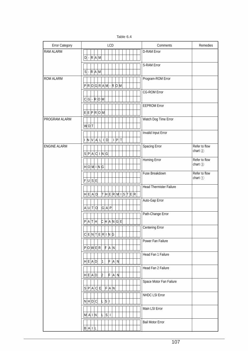
107
Table 6.4
D - R A M
S - R A M
P R O G R A M - R O M
C G - R O M
E E P R O M
W D T
I N V A L I D I P T
S P A C I N G
H O M I N G
F U S E
H E A D T H E R M I S T E R
A U T O G A P
P A T H C H A N G E
C E N T E R I N G
P O W E R F A N
H E A D 1 F A N
H E A D 2 F A N
S P A C E F A N
N H D C L S I
M A I N L S I
B A I L
Error Category LCD Comments Remedies
RAM ALARM
ROM ALARM
PROGRAM ALARM
ENGINE ALARM
D-RAM Error
S-RAM Error
Program-ROM Error
CG-ROM Error
EEPROM Error
Watch Dog Time Error
Invalid Input Error
Spacing Error
Homing Error
Fuse Breakdown
Head Thermister Failure
Auto-Gap Error
Path-Change Error
Centering Error
Power Fan Failure
Head Fan 1 Failure
Head Fan 2 Failure
Space Motor Fan Failure
NHDC LSI Error
Main LSI Error
Bail Motor Error
Refer to flow chart 2
Refer to flow chart 3
Refer to flow chart 1
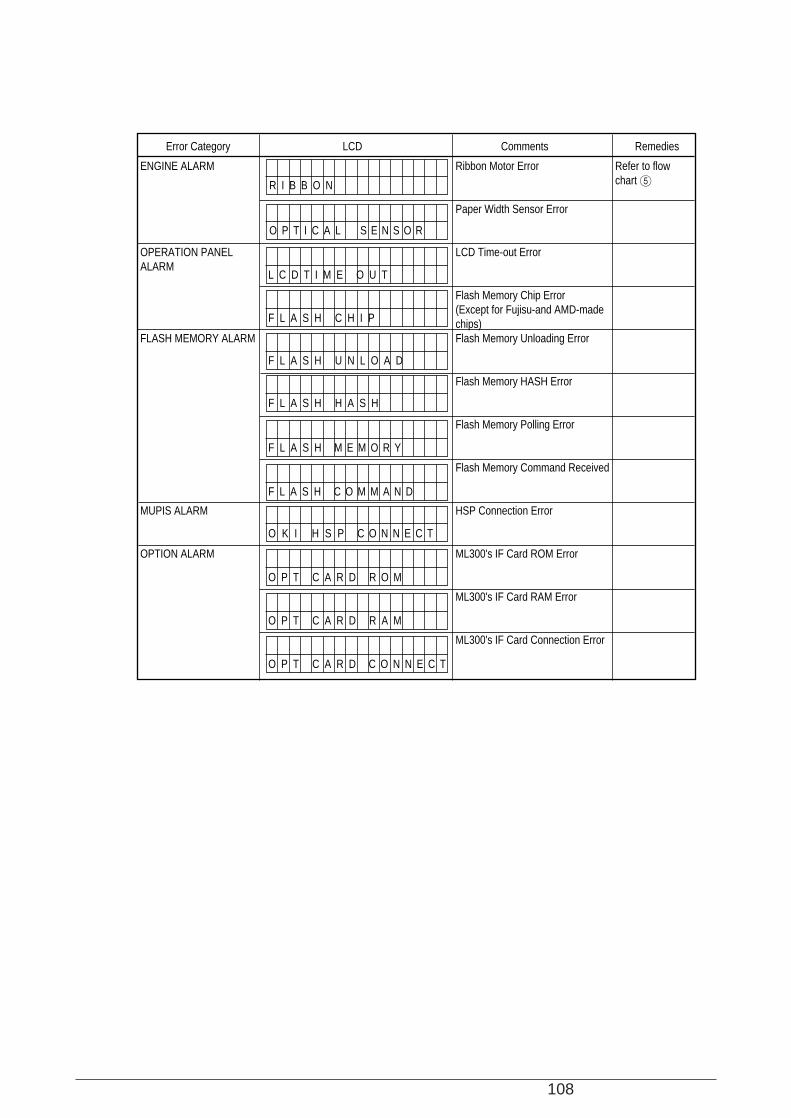
108
R I B B O N
O P T I C A L S E N S O R
L C D T I M E O U T
F L A S H C H I P
F L A S H U N L O A D
F L A S H H A S H
F L A S H M E M O R Y
F L A S H C O M M A N D
O K I H S P C O N N E C T
O P T C A R D R O M
O P T C A R D R A M
O P T C A R D C O N N E C T
Error Category LCD Comments Remedies
ENGINE ALARM
OPERATION PANEL ALARM
FLASH MEMORY ALARM
MUPIS ALARM
OPTION ALARM
Ribbon Motor Error
Paper Width Sensor Error
LCD Time-out Error
Flash Memory Chip Error(Except for Fujisu-and AMD-made chips)Flash Memory Unloading Error
Flash Memory HASH Error
Flash Memory Polling Error
Flash Memory Command Received
HSP Connection Error
ML300's IF Card ROM Error
ML300's IF Card RAM Error
ML300's IF Card Connection Error
Refer to flow chart 5

109
6.4 Part Layout
(1) Board
* SPSN-Board is illustrated on the next page (2) to define the detail positions.
PR
A
AC
Inle
t
PG
A
PO
WE
RS
UP
PLY
UN
IT
PM
A
PD
A
PHA
Con
trol
Blo
ck A
ssy
Ope
ratio
n P
anel
Ass
y
Inte
rfac
e A
ssy
LCD
UN
IT
Opt
ion
Boa
rd
PO
A
CN
2
CN
13C
N6
CN
4
CN
2
CN
5
CN
2
CN
1
CN
1
CN
4
CN
2
CN
12
CN
9
CN
8
CN10
CN5 CN3
CN8
CN1
CN9
CN6
CN13 CN11
CN5
CN7 CN6CN12
CN4
CN3 CN9
CN1
CN14
Parallel Serial
CN15
CN1
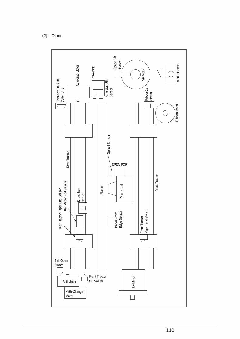
110
(2) Other
Path-ChangeMotor
Bail Motor
LF M
otor
Fron
t Tra
ctor
Pape
r End
Sw
itch
Prin
t Hea
d
Opt
ical
Sen
sor
Plat
en
Rib
bon
Mot
or
Rib
bonJ
amSe
nsor
Inte
rlock
Sw
itch
SP M
otorSp
ace
Slit
Sens
or
PGA-
PCB
Auto
-Gap
Slit
Se
nsor
Auto
-Gap
Mot
or
Con
nect
or to
Aut
o C
utte
r Uni
t
Rea
r Tra
ctor
Shee
t Jam
Sens
or
Bail
Pape
r End
Sen
sor
Rea
r Tra
ctor
Pap
er E
nd S
enso
r
Fron
t Tra
ctor
Pape
r Fro
nt
Edge
Sen
sor
Front TractorOn Switch
Bail OpenSwitch
SPSN-PCB

111
6.5 Connection
(1) Printhead
Resistance of each coil should be about 5.8Ω
CN5CN1CN1
PDA PCBPMA PCB
Head driver circuite diagramHead connector Head pin number
#1
#2
#3
#4
#5
#6
#7
#8
#9
#10
#11
#12
#13
#14
#15
#16
#17
#18
FG
NC
40, 38...4, 2
39, 37...3, 1
12
30
42
49
14
32
48
40
16
13
46
47
24
15
44
45
18
17
43
41
20
19
39
37
22
21
38
35
23
27
34
33
28
29
31
36
58
18
54
14
50
10
46
6
53
13
57
17
45
5
42
2
49
9
48
8
41
1
44
4
56
16
52
12
43
3
47
7
51
11
55
15
2
20
32
39
4
22
38
30
6
3
36
37
14
5
34
35
8
7
33
31
10
9
29
27
12
11
28
25
13
17
24
23
18
19
21
26
11
25
50
26
1
15
40
16HD THNG-N
HD THALM-N
HD ALMLOW-N
HEADTH
HEADTH-COM
FG
NC
HDT1-01-N
HDT20-01-P
HDT1-02-N
HDT20-02-P
HDT1-03-N
HDT20-03-P
HDT1-04-N
HDT20-04-P
HDT1-05-N
HDT20-05-P
HDT1-06-N
HDT20-06-P
HDT1-07-N
HDT20-07-P
HDT1-08-N
HDT20-08-P
HDT1-09-N
HDT20-09-P
HDT1-10-N
HDT20-10-P
HDT1-11-N
HDT20-11-P
HDT1-12-N
HDT20-12-P
HDT1-13-N
HDT20-13-P
HDT1-14-N
HDT20-14-P
HDT1-15-N
HDT20-15-P
HDT1-16-N
HDT20-16-P
HDT1-17-N
HDT20-17-P
HDT1-18-N
HDT20-18-P
HD THNG-N
HD THALM-N
HD ALMLOW-N
HDT1-01-N
HDT20-01-P
HDT1-02-N
HDT20-02-P
HDT1-03-N
HDT20-03-P
HDT1-04-N
HDT20-04-P
HDT1-05-N
HDT20-05-P
HDT1-06-N
HDT20-06-P
HDT1-07-N
HDT20-07-P
HDT1-08-N
HDT20-08-P
HDT1-09-N
HDT20-09-P
HDT1-10-N
HDT20-10-P
HDT1-11-N
HDT20-11-P
HDT1-12-N
HDT20-12-P
HDT1-13-N
HDT20-13-P
HDT1-14-N
HDT20-14-P
HDT1-15-N
HDT20-15-P
HDT1-16-N
HDT20-16-P
HDT1-17-N
HDT20-17-P
HDT1-18-N
HDT20-18-P
HD01-N
HD01-P
HD02-N
HD02-P
HD03-N
HD03-P
HD04-N
HD04-P
HD05-N
HD05-P
HD06-N
HD06-P
HD07-N
HD07-P
HD08-N
HD08-P
HD09-N
HD09-P
HD10-N
HD10-P
HD11-N
HD11-P
HD12-N
HD12-P
HD13-N
HD13-P
HD14-N
HD14-P
HD15-N
HD15-P
HD16-N
HD16-P
HD17-N
HD17-P
HD18-N
HD18-P
Head 60
59
61
58
18
54
14
50
10
46
6
53
13
57
17
45
5
42
2
49
9
48
8
41
1
44
4
56
16
52
12
43
3
47
7
51
11
55
15
60
59
61
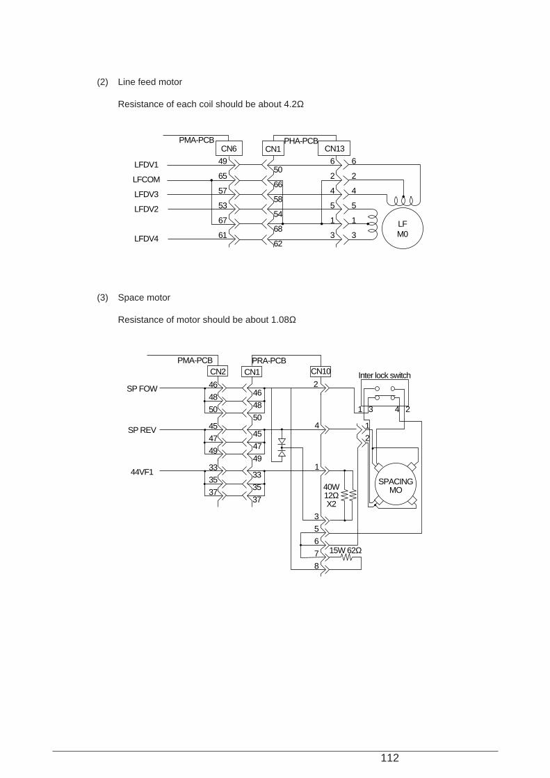
112
(2) Line feed motor
Resistance of each coil should be about 4.2Ω
(3) Space motor
Resistance of motor should be about 1.08Ω
PMA-PCBCN6
49
65
57
53
67
61
6
2
4
5
1
3
6
2
4
5
1
3
50
66
58
54
68
62
CN1 CN13
LFM0
PHA-PCB
LFDV1
LFCOM
LFDV3
LFDV2
LFDV4
PMA-PCB
46
48
50
PRA-PCB
Inter lock switchCN10CN2
SP FOW
SP REV
44VF1
45
47
49
33
35
37
33
35
37
46
48
50
2
4
1
45
47
49
3
5
6
7
8
1
2
CN1
SPACINGMO40W
12ΩX2
15W 62Ω
1 3 4 2
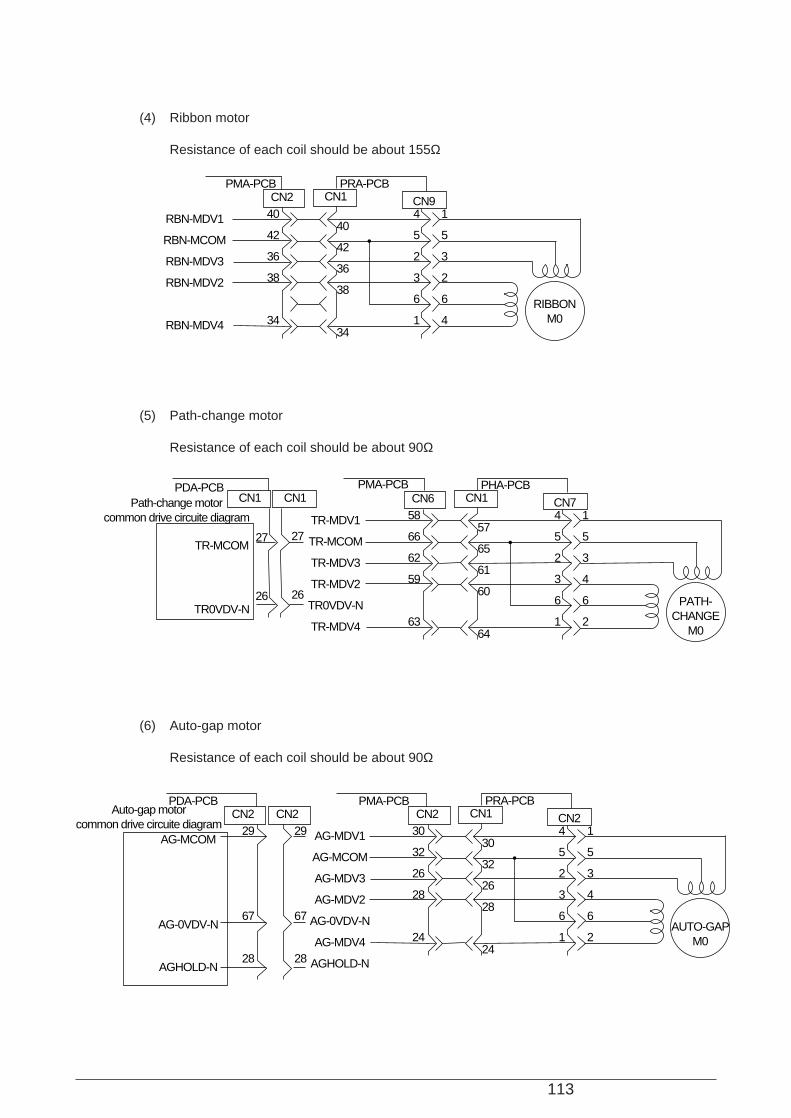
113
(4) Ribbon motor
Resistance of each coil should be about 155Ω
(5) Path-change motor
Resistance of each coil should be about 90Ω
(6) Auto-gap motor
Resistance of each coil should be about 90Ω
PMA-PCBCN2
40
42
36
38
34
4
5
2
3
6
1
1
5
3
2
6
4
40
42
36
38
34
CN1 CN9
RIBBONM0
PRA-PCB
RBN-MDV1
RBN-MCOM
RBN-MDV3
RBN-MDV2
RBN-MDV4
PMA-PCBPDA-PCBCN6
58
66
62
59
63
4
5
2
3
6
1
1
5
3
4
6
2
57
65
61
60
64
CN1 CN7
PATH-CHANGE
M0
PHA-PCB
TR-MDV1
TR-MCOM
TR-MDV3
TR-MDV2
TR0VDV-N
TR-MDV4
TR-MCOM
TR0VDV-N
CN1CN1Path-change motorcommon drive circuite diagram
27
26
27
26
PMA-PCBCN2
30
32
26
28
24
29
67
28
29
67
28
4
5
2
3
6
1
1
5
3
4
6
2
30
32
26
28
24
CN1 CN2
AUTO-GAPM0
PRA-PCB
AG-MDV1
AG-MCOM
AG-MDV3
AG-MDV2
AG-0VDV-N
AG-MDV4
AGHOLD-N
AG-MCOM
AG-0VDV-N
AGHOLD-N
CN2CN2PDA-PCB
Auto-gap motorcommon drive circuite diagram
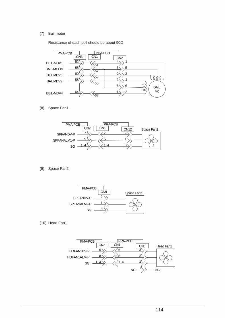
114
(7) Bail motor
Resistance of each coil should be about 90Ω
PMA-PCBCN6
52
68
60
56
64
4
5
2
3
6
1
1
5
3
4
6
2
51
67
59
55
63
CN1 CN2
BAILM0
PHA-PCB
BEIL-MDV1
BAIL-MCOM
BEILMDV3
BAILMDV2
BEIL-MDV4
(8) Space Fan1
PMA-PCBCN2
2
1
3
7
5
1~4
7
5
1~4
CN1 CN12
PRA-PCB
SPFANDV-P
SPFANALM1-P
SG
Space Fan1
(9) Space Fan2
PMA-PCBCN9
2
1
3
SPFANDV-P
SPFANALM2-P
SG
Space Fan2
(10) Head Fan1
PMA-PCBCN2
3
2
4
1
6
8
1~4
6
8
1~4
CN1 CN6
PRA-PCB
HDFAN1DV-P
HDFAN1ALM-P
SG
Head Fan1
NC NC
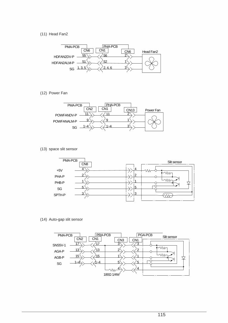
115
(11) Head Fan2
(12) Power Fan
PMA-PCBCN6
2
1
3
56
52
2, 4, 6
55
51
1, 3, 5
CN1 CN6
PHA-PCB
HDFAN2DV-P
HDFAN2ALM-P
SG
Head Fan2
PMA-PCBCN2
2
1
3
11
9
1~4
11
9
1~4
CN1 CN13
PHA-PCB
POWFANDV-P
POWFANALM-P
SG
Power Fan
(13) space slit sensor
PMA-PCBCN8
4
2
1
5
3
4
2
1
5
3
Slit sensor
+5V
PHA-P
PHB-P
SG
SPTH-P
(14) Auto-gap slit sensor
PMA-PCBCN2
17
13
15
1~4
17
13
15
1~4
3
2
1
5
4
3
2
1
5
4
CN1 CN3
PRA-PCB PGA-PCB Slit sensor
SNS5V-1
AGA-P
AGB-P
SG
CN1
180Ω 1/4W
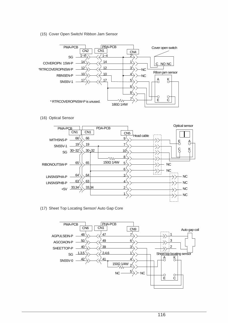
116
(15) Cover Open Switch/ Ribbon Jam Sensor
PMA-PCBCN2
1~4
14
12
10
17
1~4
14
12
10
17
2
1
3
4
5
6
8
7
CN1 CN4
NC
NC
C
A K
E C
NO NC
PRA-PCB
SG
COVEROPN 1SW-P
*RTRCOVEROPNSW-P
RBNSEN-P
SNS5V-1
180Ω 1/4W* RTRCOVEROPNSW-P is unused.
Cover open switch
Ribon jam sensor
(16) Optical Sensor
PMA-PCBCN1
9
7
10
8
5
6
3
4
2
1
NC
NC
NC
NC
NC
NC
66
19
30~32
65
64
63
33,34
66
19
30~32
65
64
63
33,34
CN5
E A
C K
PDA-PCB
WITHSNS-P
SNS5V-1
SG
RIBONOUTSW-P
LINSNSPHA-P
LINSNSPHB-P
+5V
CN1
150Ω 1/4W
Optical sensor
Head cable
(17) Sheet Top Locating Sensor/ Auto Gap Core
PMA-PCBCN6
48
50
40
1,3,5
42
47
49
39
2,4,6
41
NCNC
7
6
3
1
4
2
5
1
3
2
CN1 CN9
A K
E C
PHA-PCB
AGPULSEIN-P
AGCOAON-P
SHEETTOP-P
SG
SNS5V-0150Ω 1/4W
Sheet top locating sensor
Auto gap coil
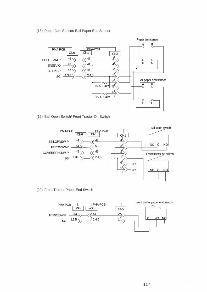
117
(18) Paper Jam Sensor/ Bail Paper End Sensor
PMA-PCBCN6
46
42
47
1,3,5
45
41
48
2,4,6
3
4
7
1
2
5
6
CN1 CN3
A K
E C
PHA-PCB
SHEETJAM-P
SNS5V-O
BEILPE-P
SG
A K
E C
150Ω 1/4W
180Ω 1/4W
Bail paper end sensor
Paper jam sensor
(19) Bail Open Switch/ Front Tractor On Switch
PMA-PCBCN6
44
54
45
1,3,5
43
53
46
2,4,6
4
3
2
1
6
5
CN1 CN1
NC
NC
NC
C NO
PHA-PCB
BEILOPNSW-P
FTRONSW-P
COVEROPN0SW-P
SG
NC C NO
Bail open switch
Front tractor on switch
(20) Front Tractor Paper End Switch
PMA-PCBCN6
43
1,3,5
44
2,4,6
2
1
CN1 CN5
NCC NO
PHA-PCB
FTRPESW-P
SG
Front tractor paper end switch
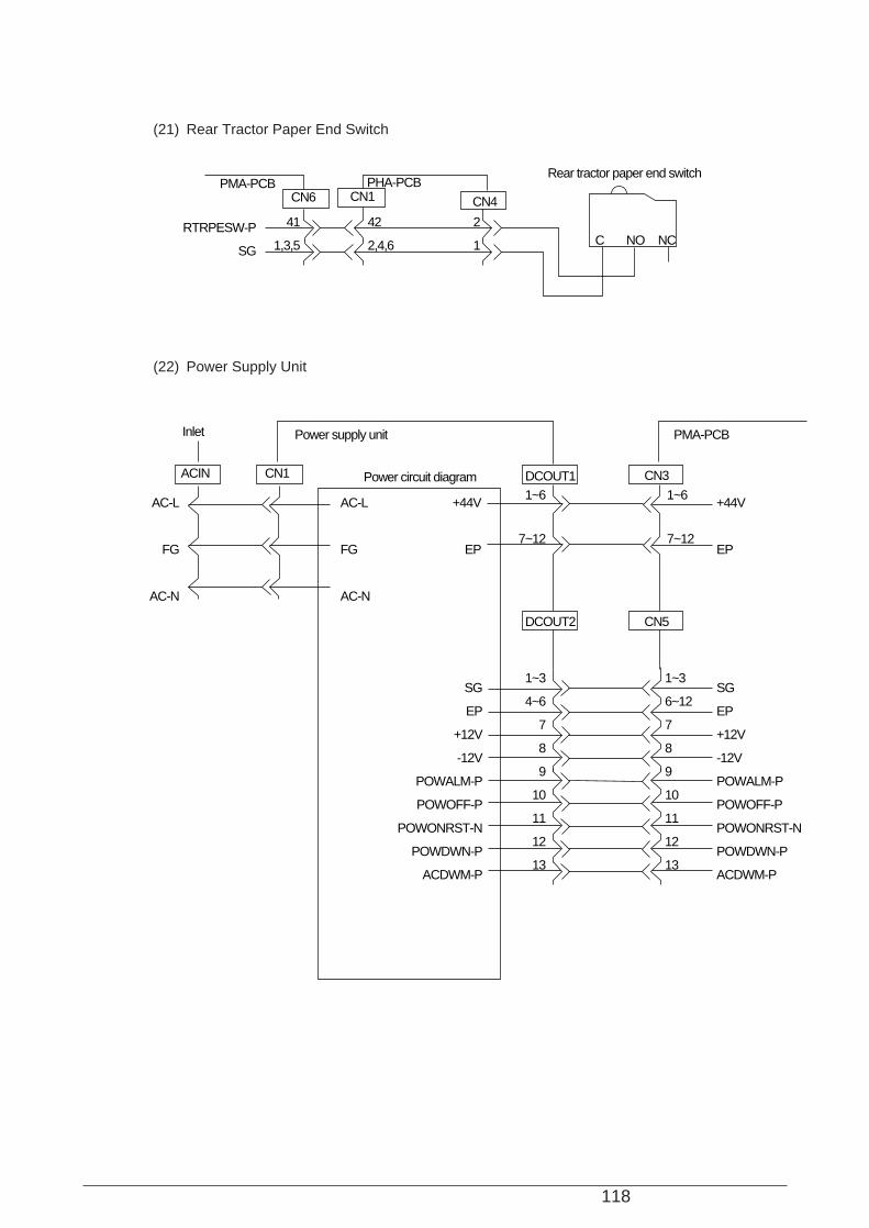
118
(21) Rear Tractor Paper End Switch
PMA-PCBCN6
41
1,3,5
42
2,4,6
2
1
CN1 CN4
NCC NO
PHA-PCB
RTRPESW-P
SG
Rear tractor paper end switch
(22) Power Supply Unit
1~3
4~6
7
8
9
10
11
12
13
1~6
7~12
1~6
7~12
+44V
EP
+44V
EP
AC-L
FG
AC-N
AC-L
FG
AC-N
1~3
6~12
7
8
9
10
11
12
13
SG
EP
+12V
-12V
POWALM-P
POWOFF-P
POWONRST-N
POWDWN-P
ACDWM-P
SG
EP
+12V
-12V
POWALM-P
POWOFF-P
POWONRST-N
POWDWN-P
ACDWM-P
ACIN
Inlet
CN1 DCOUT1Power circuit diagram
Power supply unit PMA-PCB
DCOUT2 CN5
CN3

119
(23) Operation Panel
1,12
2
3
4
5
6
7
8
9
10
11
1
2
3
4
5
6
7
8
9
10
11
12
13
14
16
15
SG
+5V
+4V
RS
R/W
E
NC
NC
NC
NC
DB4
DB5
DB6
DB7
SG
BL5V
SG
+5V
+4V
RS
R/W
E
DB4
DB5
DB6
DB7
BL5V
CN2
38
26
28
30
32
36
34
4
1,3,5
37
25
27
29
31
35
33
3
2,4,6
1
2
3
4
5
6
7
8
9,10
SHIFTSWON-N
OPSCLK-N
OPDATAOUT-P
OPDATAIN-P
OPQCR-N
BZON-P
+5VD
+5V
SG
SHIFTSWON-N
OPSCLK-N
OPDATAOUT-P
OPDATAIN-P
OPQCR-N
BZON-P
+5VD
+5V
SG
OPeration panel cirduit diagram
PMA-PCB PHA-PCB POA-PCB
CN6 CN1 CN2 CN1
LCD UNIT
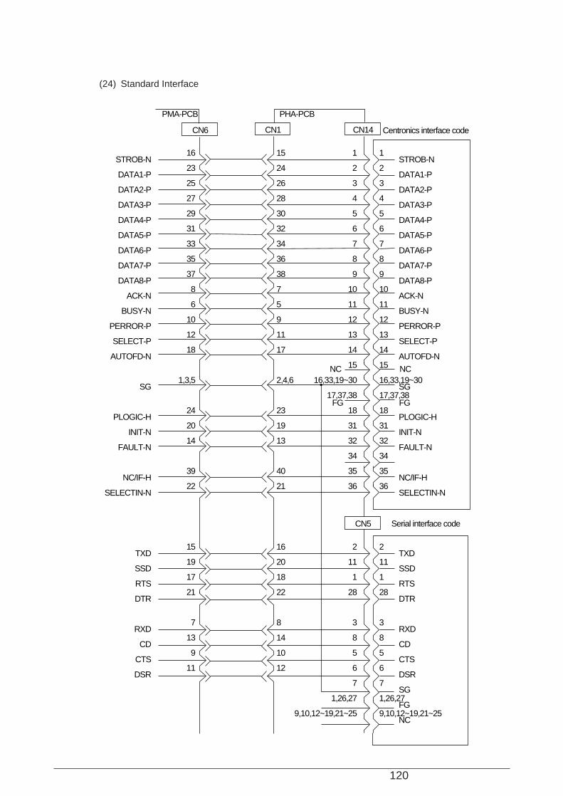
120
(24) Standard Interface
16
23
25
27
29
31
33
35
37
8
6
10
12
18
1,3,5
24
20
14
39
22
15
19
17
21
7
13
9
11
STROB-N
DATA1-P
DATA2-P
DATA3-P
DATA4-P
DATA5-P
DATA6-P
DATA7-P
DATA8-P
ACK-N
BUSY-N
PERROR-P
SELECT-P
AUTOFD-N
SG
PLOGIC-H
INIT-N
FAULT-N
NC/IF-H
SELECTIN-N
TXD
SSD
RTS
DTR
RXD
CD
CTS
DSR
STROB-N
DATA1-P
DATA2-P
DATA3-P
DATA4-P
DATA5-P
DATA6-P
DATA7-P
DATA8-P
ACK-N
BUSY-N
PERROR-P
SELECT-P
AUTOFD-N
SG
PLOGIC-H
INIT-N
FAULT-N
NC/IF-H
SELECTIN-N
TXD
SSD
RTS
DTR
RXD
CD
CTS
DSR
SG
FG
NC
1
2
3
4
5
6
7
8
9
10
11
12
13
14
15
16,33,19~30
17,37,38
18
31
32
34
35
36
2
11
1
28
3
8
5
6
7
1,26,27
9,10,12~19,21~25
1
2
3
4
5
6
7
8
9
10
11
12
13
14
15
16,33,19~30
17,37,38
18
31
32
34
35
36
2
11
1
28
3
8
5
6
7
1,26,27
9,10,12~19,21~25
15
24
26
28
30
32
34
36
38
7
5
9
11
17
2,4,6
23
19
13
40
21
16
20
18
22
8
14
10
12
PMA-PCB PHA-PCB
CN6 CN1 CN14
CN5
Centronics interface code
Serial interface code
NC
FG FG
NC
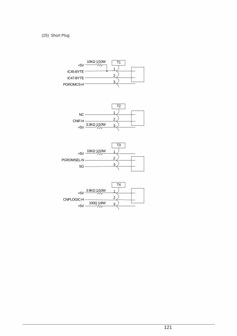
121
(25) Short Plug
1
2
3
T1+5V
IC45-BYTE
IC47-BYTE
PGROMCS-H
1
2
3
T2
NC
CNIF-H
+5V
10KΩ 1/10W
3.3KΩ 1/10W
1
2
3
T3
+5V
PGROMSEL-N
SG
10KΩ 1/10W
1
2
3
T4
+5V
CNPLOGIC-H
+5V
3.9KΩ 1/10W
100Ω 1/4W
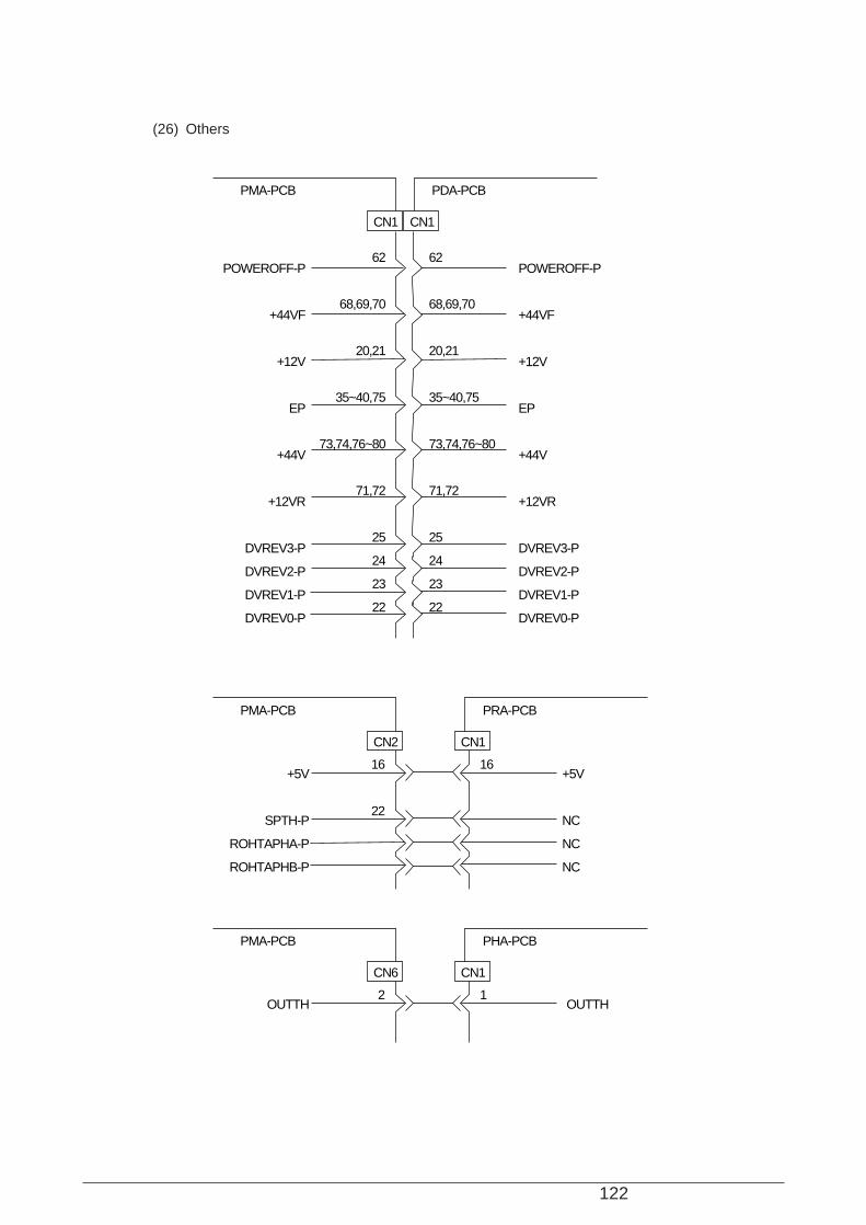
122
(26) Others
62
68,69,70
20,21
35~40,75
73,74,76~80
71,72
25
24
23
22
POWEROFF-P
+44VF
+12V
EP
+44V
+12VR
DVREV3-P
DVREV2-P
DVREV1-P
DVREV0-P
POWEROFF-P
+44VF
+12V
EP
+44V
+12VR
DVREV3-P
DVREV2-P
DVREV1-P
DVREV0-P
62
68,69,70
20,21
35~40,75
73,74,76~80
71,72
25
24
23
22
PMA-PCB PDA-PCB
CN1 CN1
PMA-PCB PRA-PCB
CN2 CN1
16
22
+5V
SPTH-P
ROHTAPHA-P
ROHTAPHB-P
+5V
NC
NC
NC
16
PMA-PCB PHA-PCB
CN6 CN1
2OUTTH OUTTH
1

123
(27) MUPIS Interface (Option)
A1A2A3A4A5A6A7A8A9
A10A11A12A13A14A15A16A17A18A19A20A21A22A23A24A25A26A27A28A29A30A31A32
MPSD01-PMPSD10-PMPSD02-P
MPSD09-PMPSD01-PMPSD08-P
MPSD07-PMPSRD-NMPSA08-P
MPSA01-PMPSA02-PMPSA03-P
MPSA04-PMPSA05-PMPSA06-P
MPSA07-PMPSCE-N
MPSDECORD1-P
MPSCUREQ-NMPSOPREQ-N
OPDCT0-NNC
OPDCT1-NNCNC
MUPISARI-N
+5V
0V
MPSD04-PMPSD12-PMPSD11-PMPSD05-PMPSD13-PMPSD06-P
MPSD14-PMPSD00-PMPSD15-P
MPSA00-PMPSA15-PMPSA14-P
MPSA13-PMPSA12-PMPSA11-P
MPSA10-PMPSA09-P
MPSDECORD0-P
MPSWR-NMPSCURST-N
MPSRDY-NNC
SIFRST-MPSRST-N-12V+12V
C1C2C3C4C5C6C7C8C9
C10C11C12C13C14C15C16C17C18C19C20C21C22C23C24C25C26C27C28C29C30C31C32
CN4PMA-PCB
MUPIS CARD
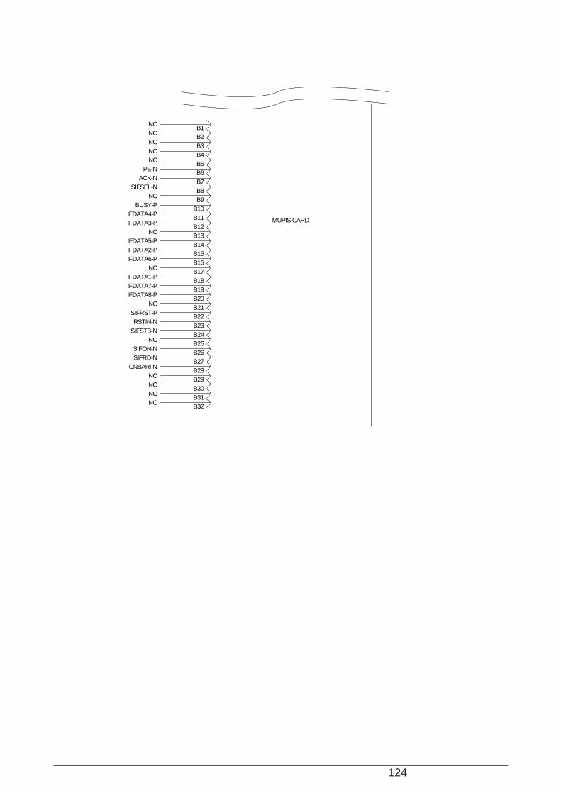
124
B1B2B3B4B5B6B7B8B9
B10B11B12B13B14B15B16B17B18B19B20B21B22B23B24B25B26B27B28B29B30B31B32
NCNCNCNCNC
PE-NACK-N
SIFSEL-NNC
BUSY-PIFDATA4-PIFDATA3-P
NCIFDATA5-PIFDATA2-PIFDATA6-P
NCIFDATA1-PIFDATA7-PIFDATA8-P
NCSIFRST-PRSTIN-N
SIFSTB-NNC
SIFON-NSIFRD-N
CNBARI-NNCNCNCNC
MUPIS CARD
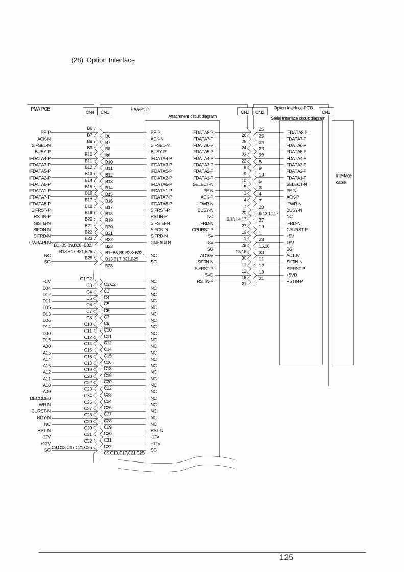
125
(28) Option Interface
B6B7B8B9
B10B11B12B13B14B15B16B17B18B19B20B21B22B23
B1~B5,B9,B28~B32,B13,B17,B21,B25
B28
B6B7B8B9B10B11B12B13B14B15B16B17B18B19B20B21B22B23B1~B5,B9,B28~B32,B13,B17,B21,B25B28
262524232289105347206,13,14,17271912815,163011121821
262524232289
105347
206,13,14,17
27191
2815,16
3011121821
PE-PACK-N
SIFSEL-NBUSY-P
IFDATA4-PIFDATA3-PIFDATA5-PIFDATA2-PIFDATA6-PIFDATA1-PIFDATA7-PIFDATA8-PSIFRST-PRSTIN-PSISTB-NSIFON-NSIFRD-N
CWBARI-N
NCSG
+5VD04D12D11D05D13D06D14D00D15A00A15A14A13A12A11A10A09
DECODE0WR-N
CURST-NRDY-N
NCRST-N
-12V+12V
SG
PE-PACK-NSIFSEL-NBUSY-PIFDATA4-PIFDATA3-PIFDATA5-PIFDATA2-PIFDATA6-PIFDATA1-PIFDATA7-PIFDATA8-PSIFRST-PRSTIN-PSIFSTB-NSIFON-NSIFRD-NCNBARI-N
NCSG
NCNCNCNCNCNCNCNCNCNCNCNCNCNCNCNCNCNCNCNCNCNCNCRST-N-12V+12VSG
IFDATA8-PFDATA7-PFDATA6-PFDATA5-PFDATA4-PFDATA3-PFDATA2-PFDATA1-PSELECT-N
PE-NACK-P
IFWR-NBUSY-N
NCIFRD-N
CPURST-P+5V+8VSG
AC10VSIF0N-N
SIFRST-P+5VD
RSTIN-P
IFDATA8-PFDATA7-PFDATA6-PFDATA5-PFDATA4-PFDATA3-PFDATA2-PFDATA1-PSELECT-NPE-NACK-PIFWR-NBUSY-NNCIFRD-NCPURST-P+5V+8VSGAC10VSIF0N-NSIFRST-P+5VDRSTIN-PC1,C2
C3C4C5C6C7C8
C10C11C12C14C15C16C18C19C20C22C23C24C26C27C28C29C30C31C32
C9,C13,C17,C21,C25
C1,C2C3C4C5C6C7C8C10C11C12C14C15C16C18C19C20C22C23C24C26C27C28C29C30C31C32C9,C13,C17,C21,C25
CN4 CN1 CN2 CN1CN2PMA-PCB PAA-PCB Option Interface-PCB
Attachment circuit diagram Serial Interface circuit diagram
Interfacecable

126
A1A2A3A4A6A7A8
A10A11A12A14A15A16A18A19A20A22A23A24A26A27A28A29
A5,A9,A13A21,A25
A2~A4,A5~A8,A10~A12,A14~A20,A22~A24,A26~A32
A1A2A3A4A6A7A8A10A11A12A14A15A16A18A19A20A22A23A24A26A27A28A29
A5,A9,A13A21,A25
A2~A4,A5~A8,A10~A12,A14~A20,A22~A24,A26~A32
+5VD03D10D12D09D01D08D07
RD-NA08A01A02A03A04A05A06A07
CE-NDECODE1CUREQ-NOPREQ-N
OPDCT0-NOPDCT1-N
SG
NC
+5VD03D10D12D09D01D08D07RD-NA08A01A02A03A04A05A06A07CE-NDECODE1CUREQ-NOPREQ-NOPDCT0-NOPDCT1-N
SG
NC

127
(29) Continuous-Form Paper Cutter (Option)
39,41,43,44
31
29
27
25
23
21
19
1~4
39,41,43,44
31
29
27
25
23
21
19
1~4
9
8
7
6
5
4
3
2
1
EP
44VF
CUTMOYDV-P
CUTM1-P
CUTM2-P
CUTM3-P
CUTM4-P
RENCUT-N
SG
PMA-PCB PRA-PCB
CN2 CN1 CN8
CONTINUOUS-FORM PAPER CUTTER
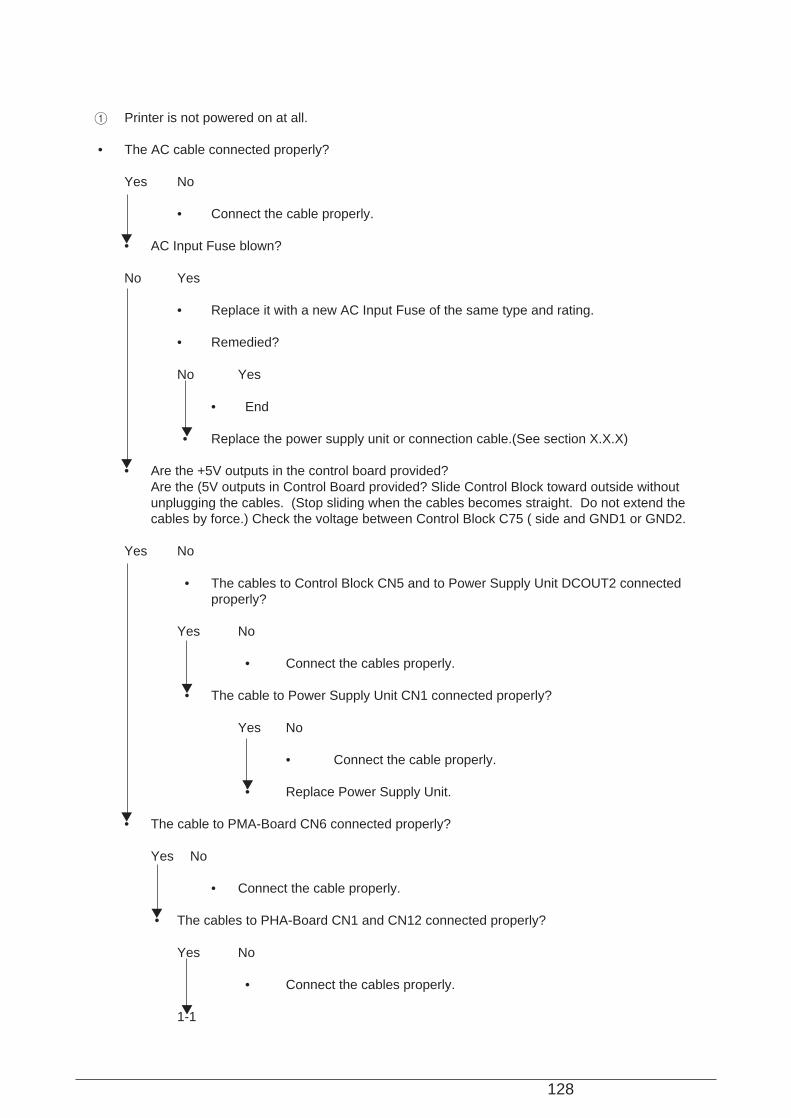
128
1 Printer is not powered on at all.
• The AC cable connected properly?
Yes No
• Connect the cable properly.
• AC Input Fuse blown?
No Yes
• Replace it with a new AC Input Fuse of the same type and rating.
• Remedied?
No Yes
• End
• Replace the power supply unit or connection cable.(See section X.X.X)
• Are the +5V outputs in the control board provided?Are the (5V outputs in Control Board provided? Slide Control Block toward outside withoutunplugging the cables. (Stop sliding when the cables becomes straight. Do not extend thecables by force.) Check the voltage between Control Block C75 ( side and GND1 or GND2.
Yes No
• The cables to Control Block CN5 and to Power Supply Unit DCOUT2 connectedproperly?
Yes No
• Connect the cables properly.
• The cable to Power Supply Unit CN1 connected properly?
Yes No
• Connect the cable properly.
• Replace Power Supply Unit.
• The cable to PMA-Board CN6 connected properly?
Yes No
• Connect the cable properly.
• The cables to PHA-Board CN1 and CN12 connected properly?
Yes No
• Connect the cables properly.
1-1

129
1-1
• The cable to POA-Board CN1 connected properly?
Yes No
• Connect the cable properly.
• Replace POA-Board or PMA-Board.

130
2 Printer does not operate at all, while Power Lamp is on, Alarm Lamp blinks and nothing is displayedon LCD.
• The cable to POA-Board CN2 connected properly?
Yes No
• Connect the cable properly.
• Replace LCD Unit.
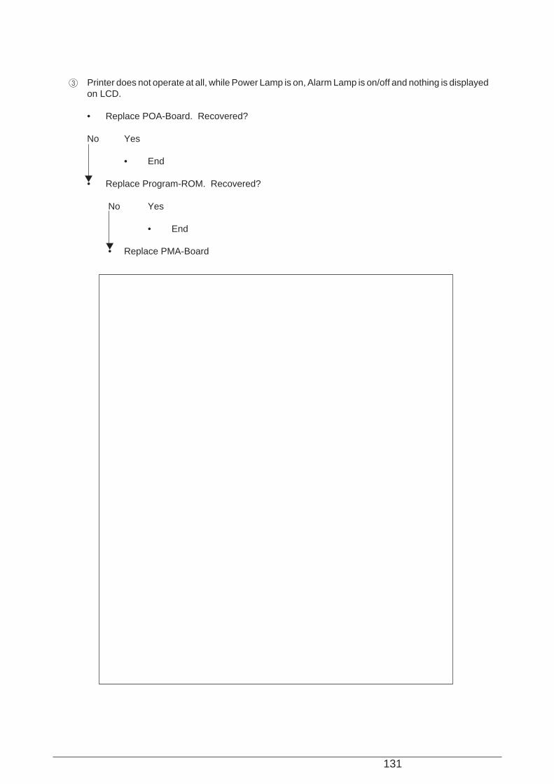
131
3 Printer does not operate at all, while Power Lamp is on, Alarm Lamp is on/off and nothing is displayedon LCD.
• Replace POA-Board. Recovered?
No Yes
• End
• Replace Program-ROM. Recovered?
No Yes
• End
• Replace PMA-Board
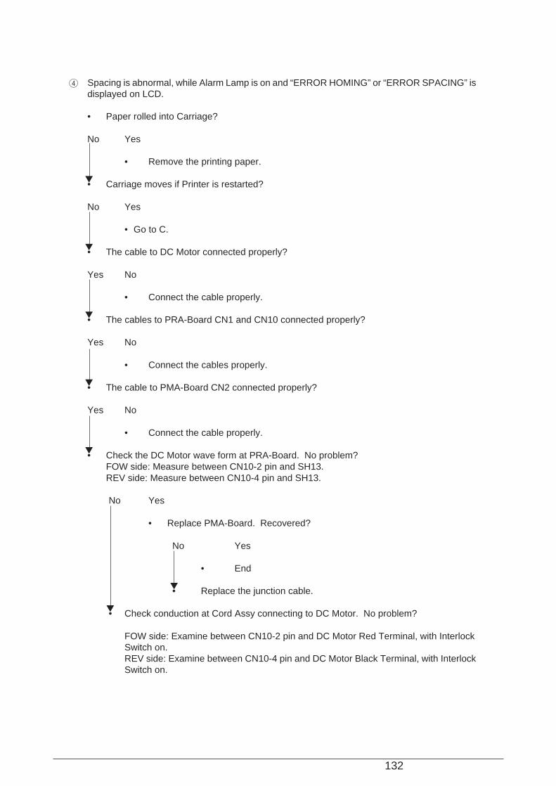
132
4 Spacing is abnormal, while Alarm Lamp is on and “ERROR HOMING” or “ERROR SPACING” isdisplayed on LCD.
• Paper rolled into Carriage?
No Yes
• Remove the printing paper.
• Carriage moves if Printer is restarted?
No Yes
• Go to C.
• The cable to DC Motor connected properly?
Yes No
• Connect the cable properly.
• The cables to PRA-Board CN1 and CN10 connected properly?
Yes No
• Connect the cables properly.
• The cable to PMA-Board CN2 connected properly?
Yes No
• Connect the cable properly.
• Check the DC Motor wave form at PRA-Board. No problem?FOW side: Measure between CN10-2 pin and SH13.REV side: Measure between CN10-4 pin and SH13.
No Yes
• Replace PMA-Board. Recovered?
No Yes
• End
• Replace the junction cable.
• Check conduction at Cord Assy connecting to DC Motor. No problem?
FOW side: Examine between CN10-2 pin and DC Motor Red Terminal, with InterlockSwitch on.REV side: Examine between CN10-4 pin and DC Motor Black Terminal, with InterlockSwitch on.

133
No Yes
• Check conduction only at Interlock Switch. Is it normal?
Yes No
• Replace Interlock Switch.
• Replace Cord Assy.
• Replace DC Motor.
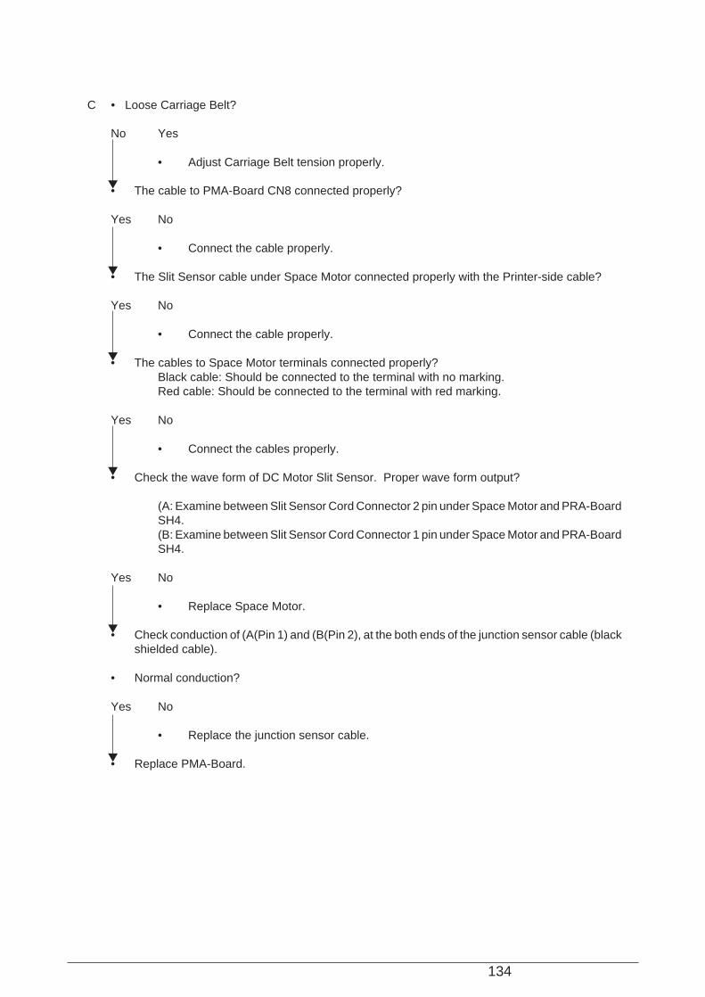
134
C • Loose Carriage Belt?
No Yes
• Adjust Carriage Belt tension properly.
• The cable to PMA-Board CN8 connected properly?
Yes No
• Connect the cable properly.
• The Slit Sensor cable under Space Motor connected properly with the Printer-side cable?
Yes No
• Connect the cable properly.
• The cables to Space Motor terminals connected properly?Black cable: Should be connected to the terminal with no marking.Red cable: Should be connected to the terminal with red marking.
Yes No
• Connect the cables properly.
• Check the wave form of DC Motor Slit Sensor. Proper wave form output?
(A: Examine between Slit Sensor Cord Connector 2 pin under Space Motor and PRA-BoardSH4.(B: Examine between Slit Sensor Cord Connector 1 pin under Space Motor and PRA-BoardSH4.
Yes No
• Replace Space Motor.
• Check conduction of (A(Pin 1) and (B(Pin 2), at the both ends of the junction sensor cable (blackshielded cable).
• Normal conduction?
Yes No
• Replace the junction sensor cable.
• Replace PMA-Board.
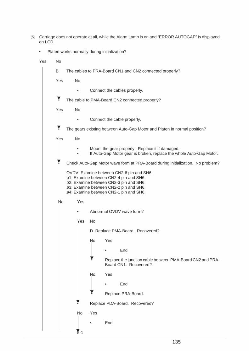
135
5 Carriage does not operate at all, while the Alarm Lamp is on and “ERROR AUTOGAP” is displayedon LCD.
• Platen works normally during initialization?
Yes No
B The cables to PRA-Board CN1 and CN2 connected properly?
Yes No
• Connect the cables properly.
• The cable to PMA-Board CN2 connected properly?
Yes No
• Connect the cable properly.
• The gears existing between Auto-Gap Motor and Platen in normal position?
Yes No
• Mount the gear properly. Replace it if damaged.• If Auto-Gap Motor gear is broken, replace the whole Auto-Gap Motor.
• Check Auto-Gap Motor wave form at PRA-Board during initialization. No problem?
OVDV: Examine between CN2-6 pin and SH6.ø1: Examine between CN2-4 pin and SH6.ø2: Examine between CN2-3 pin and SH6.ø3: Examine between CN2-2 pin and SH6.ø4: Examine between CN2-1 pin and SH6.
No Yes
• Abnormal OVDV wave form?
Yes No
D Replace PMA-Board. Recovered?
No Yes
• End
• Replace the junction cable between PMA-Board CN2 and PRA-Board CN1. Recovered?
No Yes
• End
• Replace PRA-Board.
• Replace PDA-Board. Recovered?
No Yes
• End
5-1
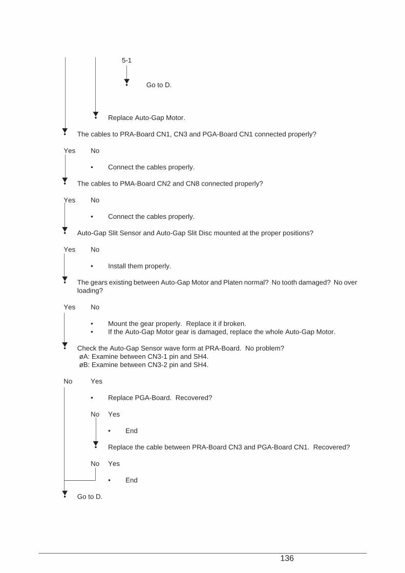
136
5-1
• Go to D.
• Replace Auto-Gap Motor.
• The cables to PRA-Board CN1, CN3 and PGA-Board CN1 connected properly?
Yes No
• Connect the cables properly.
• The cables to PMA-Board CN2 and CN8 connected properly?
Yes No
• Connect the cables properly.
• Auto-Gap Slit Sensor and Auto-Gap Slit Disc mounted at the proper positions?
Yes No
• Install them properly.
• The gears existing between Auto-Gap Motor and Platen normal? No tooth damaged? No overloading?
Yes No
• Mount the gear properly. Replace it if broken.• If the Auto-Gap Motor gear is damaged, replace the whole Auto-Gap Motor.
• Check the Auto-Gap Sensor wave form at PRA-Board. No problem?øA: Examine between CN3-1 pin and SH4.øB: Examine between CN3-2 pin and SH4.
No Yes
• Replace PGA-Board. Recovered?
No Yes
• End
• Replace the cable between PRA-Board CN3 and PGA-Board CN1. Recovered?
No Yes
• End
• Go to D.
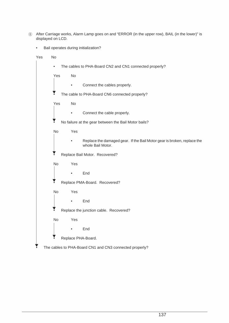
137
6 After Carriage works, Alarm Lamp goes on and “ERROR (in the upper row), BAIL (in the lower)” isdisplayed on LCD.
• Bail operates during initialization?
Yes No
• The cables to PHA-Board CN2 and CN1 connected properly?
Yes No
• Connect the cables properly.
• The cable to PHA-Board CN6 connected properly?
Yes No
• Connect the cable properly.
• No failure at the gear between the Bail Motor bails?
No Yes
• Replace the damaged gear. If the Bail Motor gear is broken, replace thewhole Bail Motor.
• Replace Bail Motor. Recovered?
No Yes
• End
• Replace PMA-Board. Recovered?
No Yes
• End
• Replace the junction cable. Recovered?
No Yes
• End
• Replace PHA-Board.
• The cables to PHA-Board CN1 and CN3 connected properly?
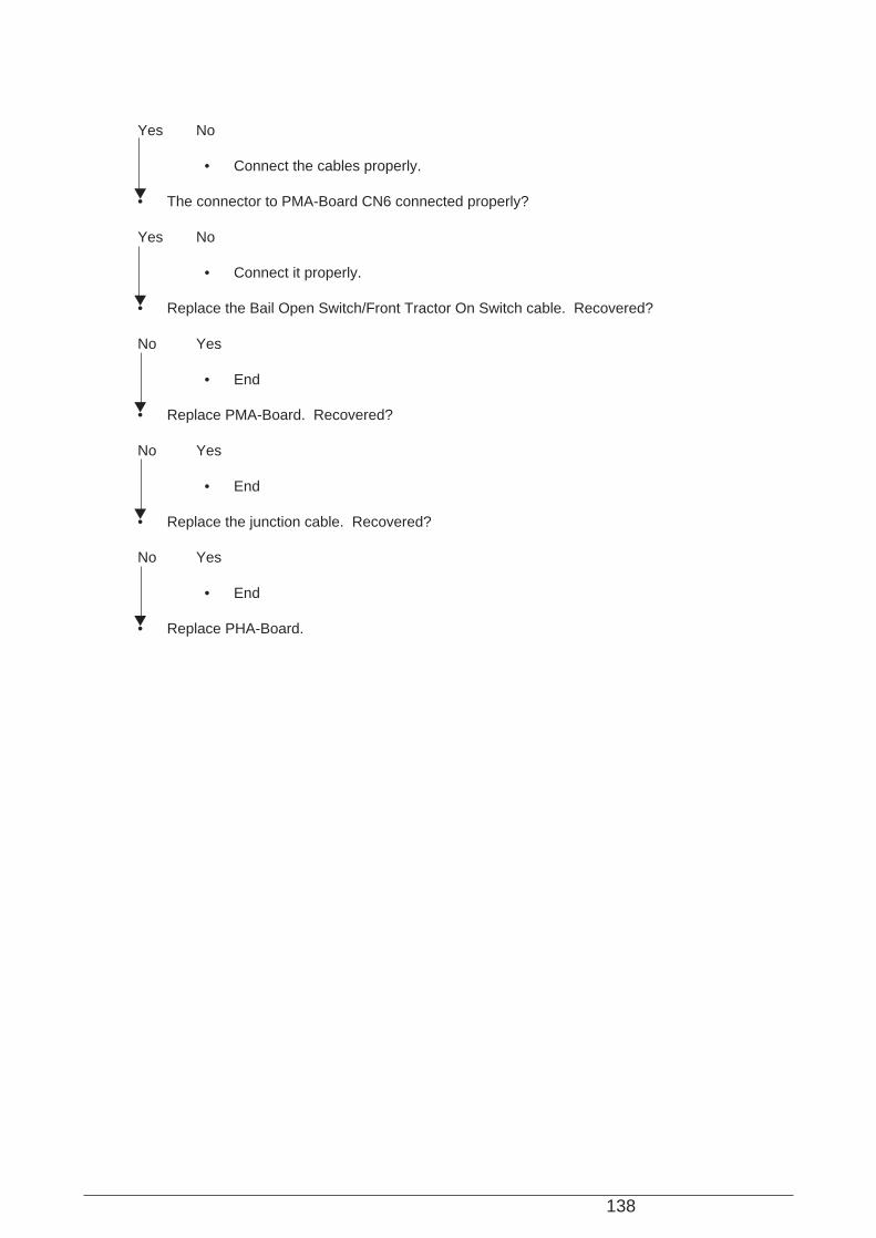
138
Yes No
• Connect the cables properly.
• The connector to PMA-Board CN6 connected properly?
Yes No
• Connect it properly.
• Replace the Bail Open Switch/Front Tractor On Switch cable. Recovered?
No Yes
• End
• Replace PMA-Board. Recovered?
No Yes
• End
• Replace the junction cable. Recovered?
No Yes
• End
• Replace PHA-Board.
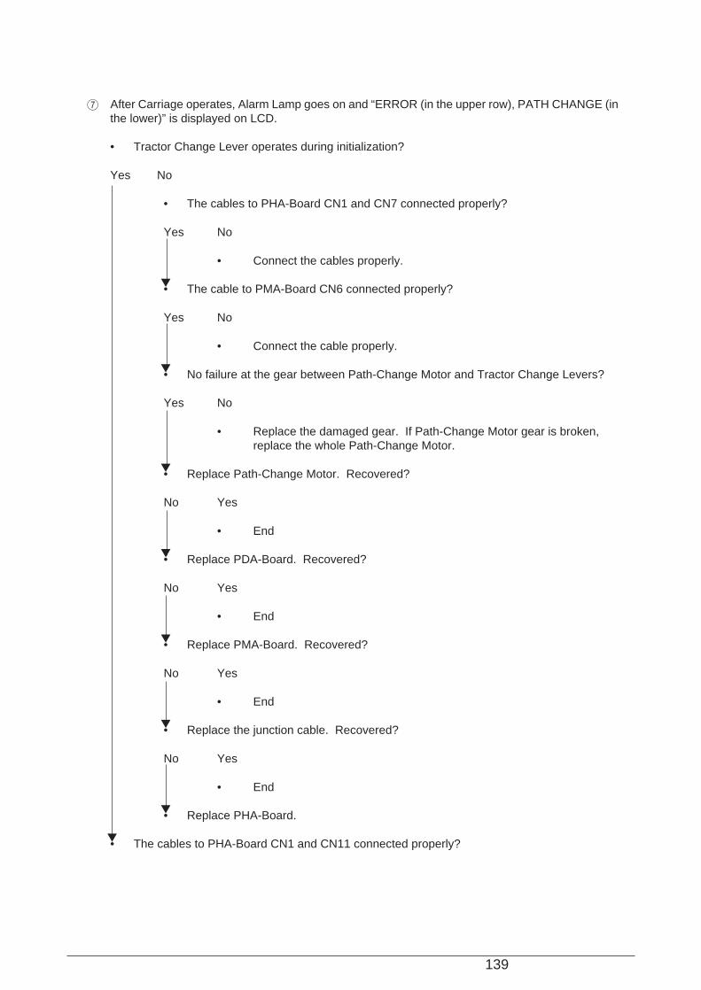
139
7 After Carriage operates, Alarm Lamp goes on and “ERROR (in the upper row), PATH CHANGE (inthe lower)” is displayed on LCD.
• Tractor Change Lever operates during initialization?
Yes No
• The cables to PHA-Board CN1 and CN7 connected properly?
Yes No
• Connect the cables properly.
• The cable to PMA-Board CN6 connected properly?
Yes No
• Connect the cable properly.
• No failure at the gear between Path-Change Motor and Tractor Change Levers?
Yes No
• Replace the damaged gear. If Path-Change Motor gear is broken,replace the whole Path-Change Motor.
• Replace Path-Change Motor. Recovered?
No Yes
• End
• Replace PDA-Board. Recovered?
No Yes
• End
• Replace PMA-Board. Recovered?
No Yes
• End
• Replace the junction cable. Recovered?
No Yes
• End
• Replace PHA-Board.
• The cables to PHA-Board CN1 and CN11 connected properly?
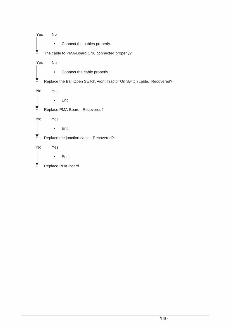
140
Yes No
• Connect the cables properly.
• The cable to PMA-Board CN6 connected properly?
Yes No
• Connect the cable properly.
• Replace the Bail Open Switch/Front Tractor On Switch cable. Recovered?
No Yes
• End
• Replace PMA-Board. Recovered?
No Yes
• End
• Replace the junction cable. Recovered?
No Yes
• End
• Replace PHA-Board.
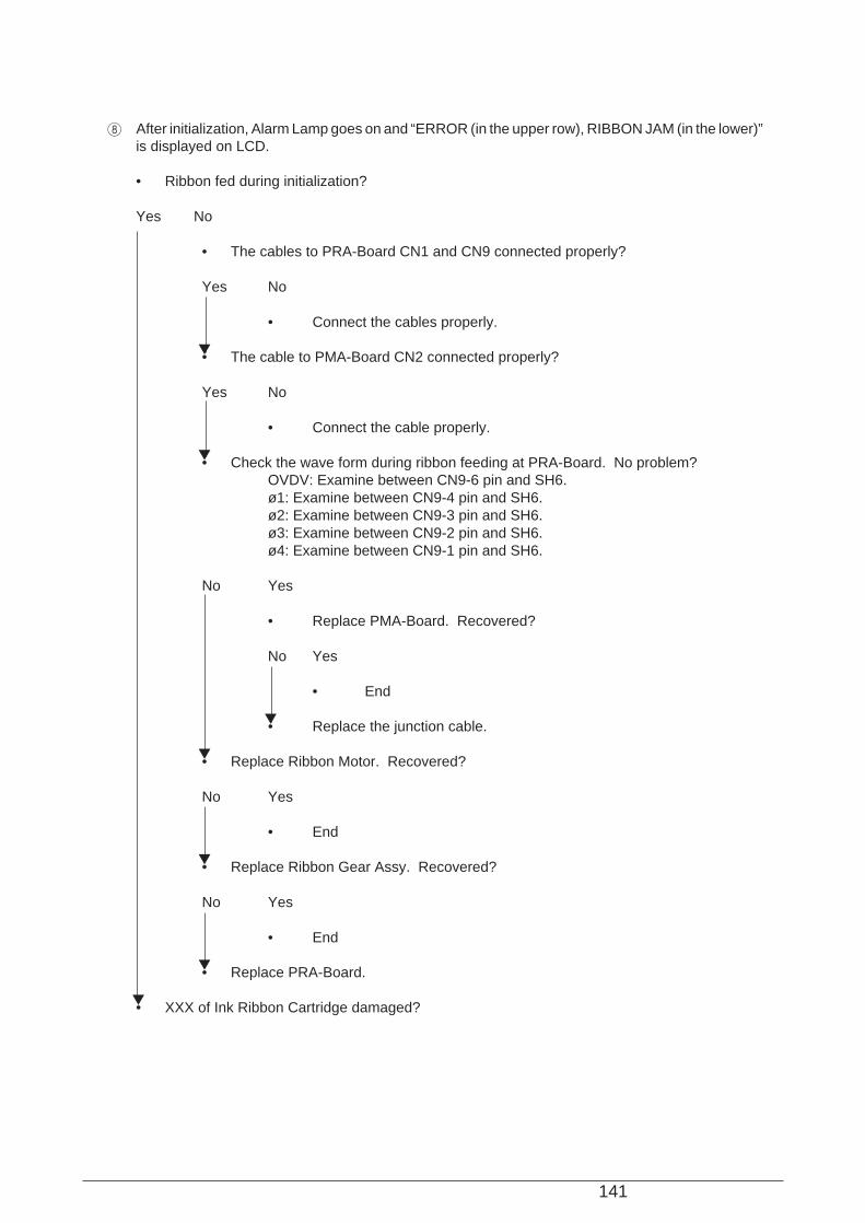
141
8 After initialization, Alarm Lamp goes on and “ERROR (in the upper row), RIBBON JAM (in the lower)”is displayed on LCD.
• Ribbon fed during initialization?
Yes No
• The cables to PRA-Board CN1 and CN9 connected properly?
Yes No
• Connect the cables properly.
• The cable to PMA-Board CN2 connected properly?
Yes No
• Connect the cable properly.
• Check the wave form during ribbon feeding at PRA-Board. No problem?OVDV: Examine between CN9-6 pin and SH6.ø1: Examine between CN9-4 pin and SH6.ø2: Examine between CN9-3 pin and SH6.ø3: Examine between CN9-2 pin and SH6.ø4: Examine between CN9-1 pin and SH6.
No Yes
• Replace PMA-Board. Recovered?
No Yes
• End
• Replace the junction cable.
• Replace Ribbon Motor. Recovered?
No Yes
• End
• Replace Ribbon Gear Assy. Recovered?
No Yes
• End
• Replace PRA-Board.
• XXX of Ink Ribbon Cartridge damaged?

142
No Yes
• Replace Ink Ribbon Cartridge.
• Check the ribbon route in Ink Ribbon Cartridge. Is it normal? XXX rotating?
Yes No
• Set the ink ribbon on the correct route.
• Ink Ribbon Rotation Sensor mounted properly?
Yes No
• Install the sensor properly.
• The cables to PRA-Board CN4 and CN1 connected properly?
Yes No
• Connect the cables properly.
• The cable to PMA-Board CN2 connected properly?
Yes No
• Connect the cable properly.
• Check the Ribbon Rotation Sensor wave form at PRA-Board. No problem?Ribbon Rotation Sensor: Examine between CN4-5 pin and SH4.
Yes No
• Replace the Cover Open Switch/Ribbon Rotation Sensor cable.
• Replace PMA-Board. Recovered?
No Yes
• End
• Replace PRA-Board. Recovered?
No Yes
• End
• Replace the junction cable.

143
9 Paper is not line fed, while the Alarm Lamp is on and “ERROR (in the upper row), FEED JAM (in thelower)” is displayed on LCD.
• The printing paper stuck on the paper feed route?
No Yes
• Remove the paper.
• The cables to PHA-Board CN1 and CN13 connected properly?
Yes No
• Connect the cables properly.
• The cable to PMA-Board CN6 connected properly?
Yes No
• Connect the cable properly.
• No failure at the gear between LF Motor and Tractor Unit?
Yes No
• Replace the broken gear. If the LF Motor gear is damaged, replace the whole LFMotor.
• Replace PMA-Board. Recovered?
No Yes
• End
• Replace LF Motor. Recovered?
No Yes
• End
• Replace the junction cable. Recovered?
No Yes
• End
• Replace PHA-Board.

144
0 Paper is line fed, but “FEED JAM” is displayed on LCD.
• The cables to PHA-Board CN1 and CN3 connected properly?
Yes No
• Connect the cables properly.
• The cable to PMA-Board CN6 Connector connected properly?
Yes No
• Connect the cable properly.
• Feed Jam Sensor mounted properly?
Yes No
• Install it properly.
• Replace the FEED JAM/Bail Paper End Sensor cable. Recovered?
No Yes
• End
• Replace PMA-Board. Recovered?
No Yes
• End
• Replace the junction cable. Recovered?
No Yes
• End
• Replace PHA-Board.
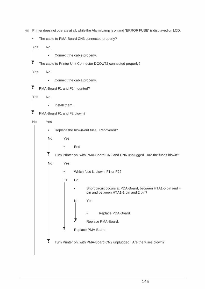
145
A Printer does not operate at all, while the Alarm Lamp is on and “ERROR FUSE” is displayed on LCD.
• The cable to PMA-Board CN3 connected properly?
Yes No
• Connect the cable properly.
• The cable to Printer Unit Connector DCOUT2 connected properly?
Yes No
• Connect the cable properly.
• PMA-Board F1 and F2 mounted?
Yes No
• Install them.
• PMA-Board F1 and F2 blown?
No Yes
• Replace the blown-out fuse. Recovered?
No Yes
• End
• Turn Printer on, with PMA-Board CN2 and CN6 unplugged. Are the fuses blown?
No Yes
• Which fuse is blown, F1 or F2?
F1 F2
• Short circuit occurs at PDA-Board, between HTA1-5 pin and 4pin and between HTA1-1 pin and 2 pin?
No Yes
• Replace PDA-Board.
• Replace PMA-Board.
• Replace PMA-Board.
• Turn Printer on, with PMA-Board CN2 unplugged. Are the fuses blown?
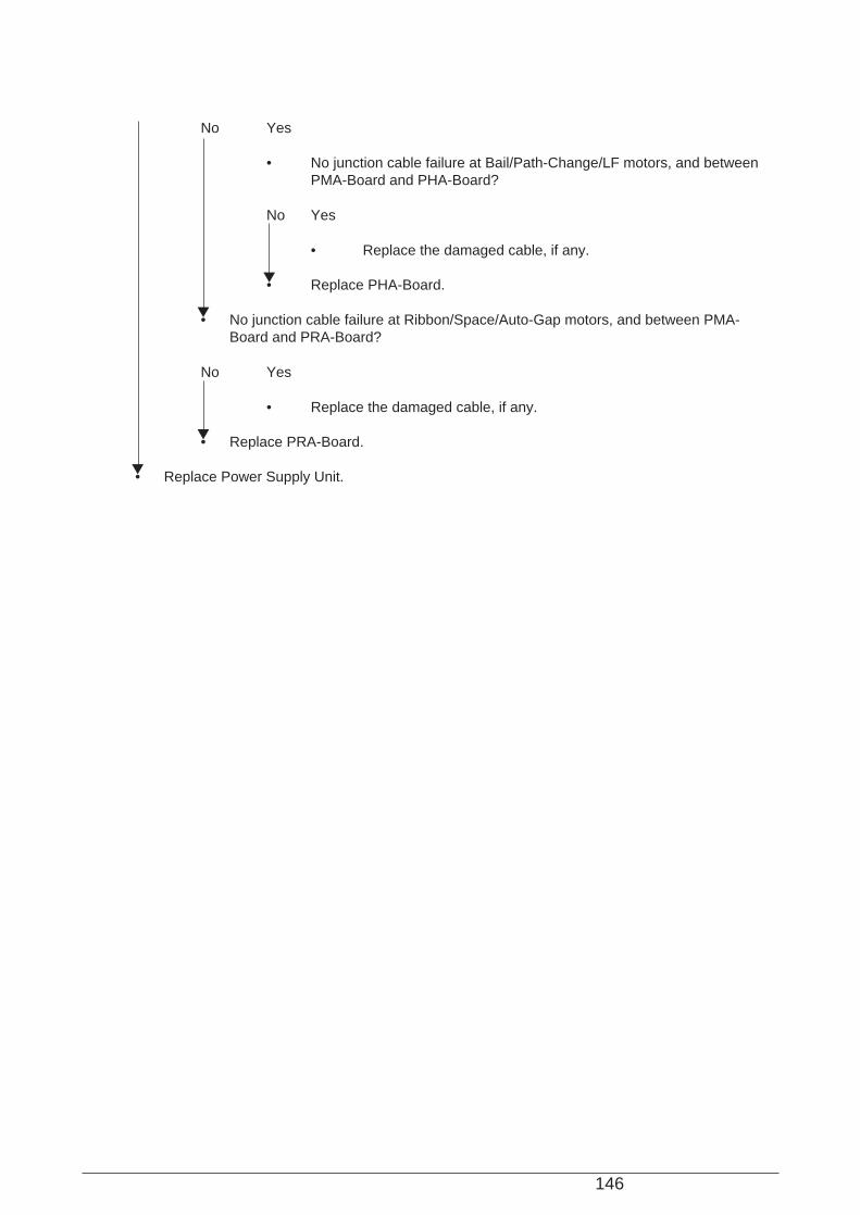
146
No Yes
• No junction cable failure at Bail/Path-Change/LF motors, and betweenPMA-Board and PHA-Board?
No Yes
• Replace the damaged cable, if any.
• Replace PHA-Board.
• No junction cable failure at Ribbon/Space/Auto-Gap motors, and between PMA-Board and PRA-Board?
No Yes
• Replace the damaged cable, if any.
• Replace PRA-Board.
• Replace Power Supply Unit.
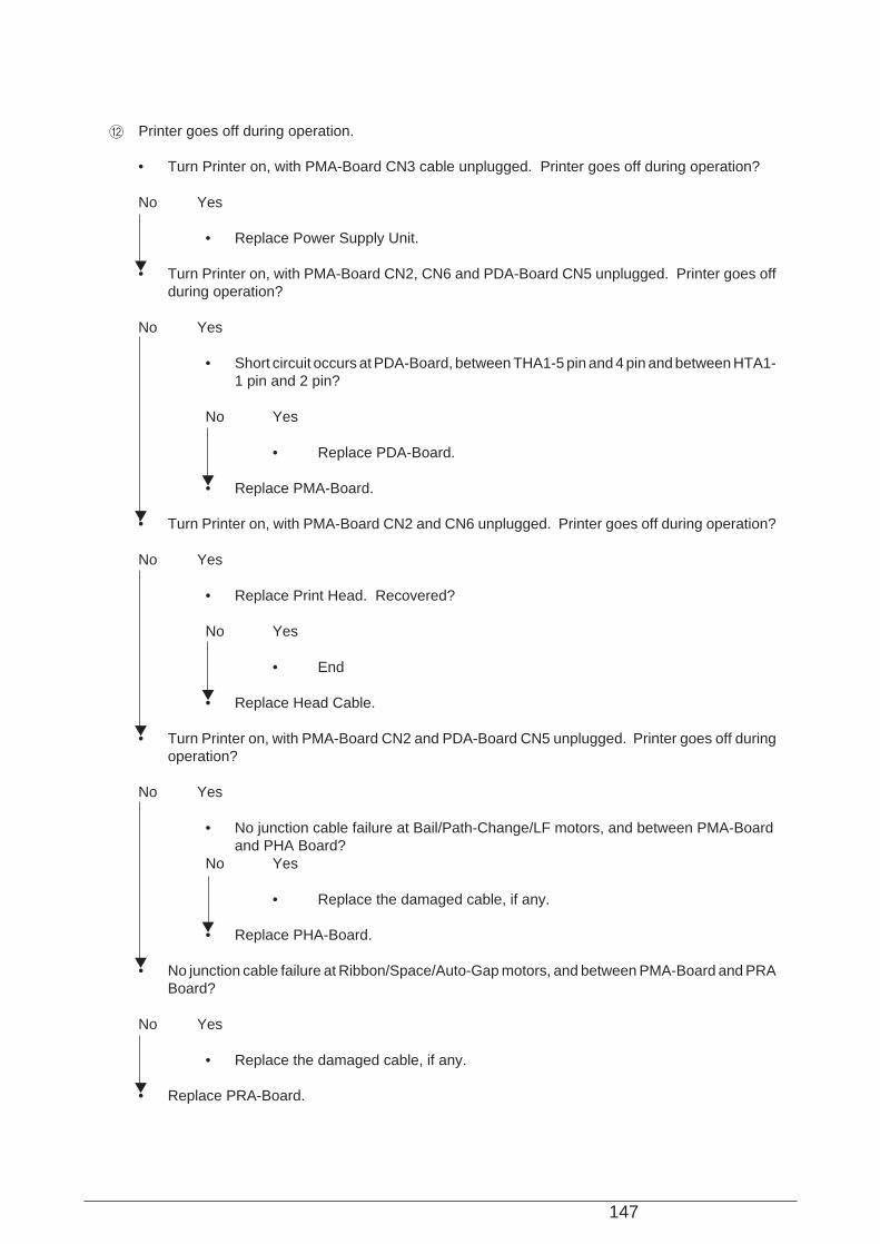
147
B Printer goes off during operation.
• Turn Printer on, with PMA-Board CN3 cable unplugged. Printer goes off during operation?
No Yes
• Replace Power Supply Unit.
• Turn Printer on, with PMA-Board CN2, CN6 and PDA-Board CN5 unplugged. Printer goes offduring operation?
No Yes
• Short circuit occurs at PDA-Board, between THA1-5 pin and 4 pin and between HTA1-1 pin and 2 pin?
No Yes
• Replace PDA-Board.
• Replace PMA-Board.
• Turn Printer on, with PMA-Board CN2 and CN6 unplugged. Printer goes off during operation?
No Yes
• Replace Print Head. Recovered?
No Yes
• End
• Replace Head Cable.
• Turn Printer on, with PMA-Board CN2 and PDA-Board CN5 unplugged. Printer goes off duringoperation?
No Yes
• No junction cable failure at Bail/Path-Change/LF motors, and between PMA-Boardand PHA Board?
No Yes
• Replace the damaged cable, if any.
• Replace PHA-Board.
• No junction cable failure at Ribbon/Space/Auto-Gap motors, and between PMA-Board and PRABoard?
No Yes
• Replace the damaged cable, if any.
• Replace PRA-Board.

148
C Printer does not operate after being turned on, while “INITIALIZING” is displayed on LCD.
• The interface cable connected properly?
Yes No
• Connect the cable properly.
• Replace the interface cable. Recovered?
No Yes
• End
• Replace PMA-Board.
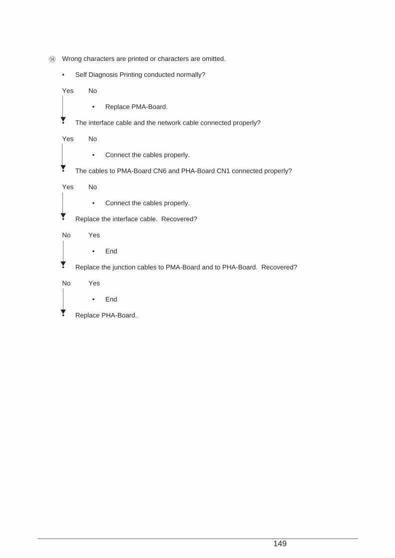
149
D Wrong characters are printed or characters are omitted.
• Self Diagnosis Printing conducted normally?
Yes No
• Replace PMA-Board.
• The interface cable and the network cable connected properly?
Yes No
• Connect the cables properly.
• The cables to PMA-Board CN6 and PHA-Board CN1 connected properly?
Yes No
• Connect the cables properly.
• Replace the interface cable. Recovered?
No Yes
• End
• Replace the junction cables to PMA-Board and to PHA-Board. Recovered?
No Yes
• End
• Replace PHA-Board.
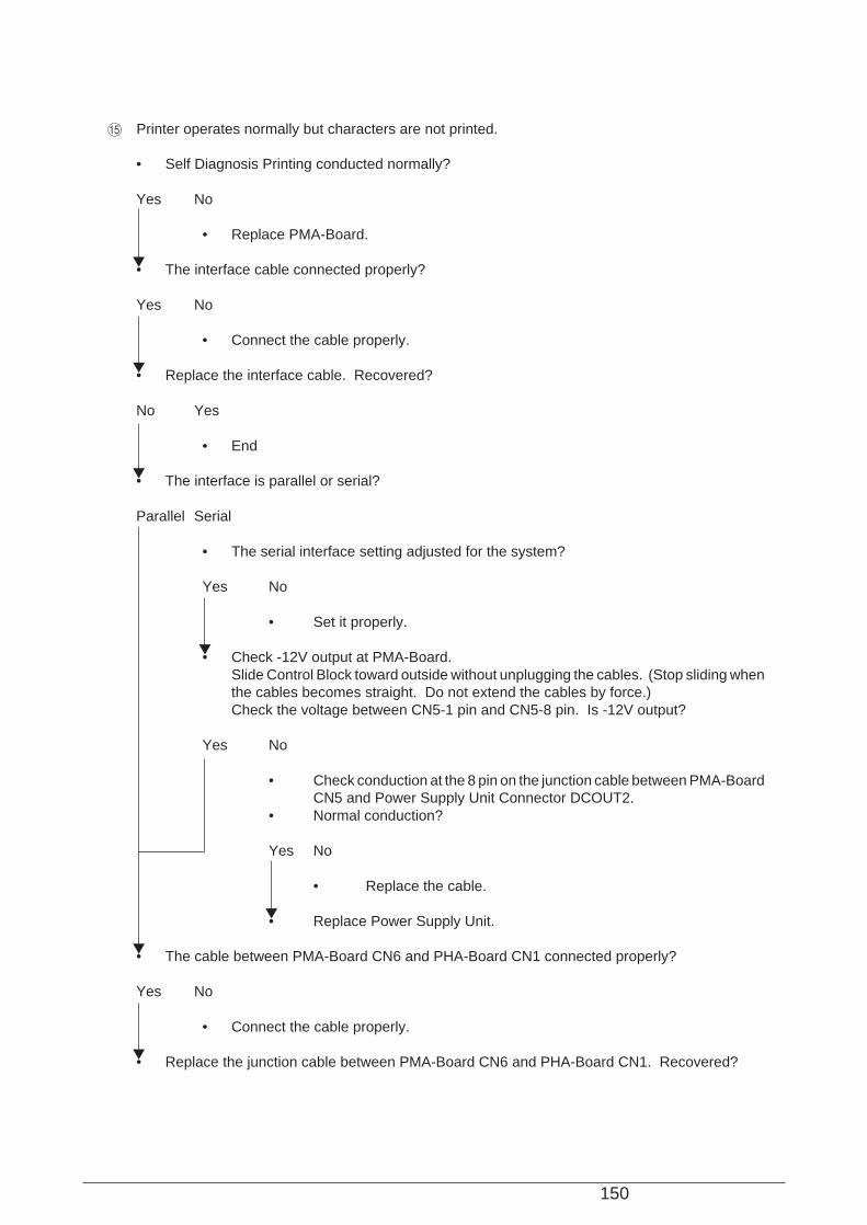
150
E Printer operates normally but characters are not printed.
• Self Diagnosis Printing conducted normally?
Yes No
• Replace PMA-Board.
• The interface cable connected properly?
Yes No
• Connect the cable properly.
• Replace the interface cable. Recovered?
No Yes
• End
• The interface is parallel or serial?
Parallel Serial
• The serial interface setting adjusted for the system?
Yes No
• Set it properly.
• Check -12V output at PMA-Board.Slide Control Block toward outside without unplugging the cables. (Stop sliding whenthe cables becomes straight. Do not extend the cables by force.)Check the voltage between CN5-1 pin and CN5-8 pin. Is -12V output?
Yes No
• Check conduction at the 8 pin on the junction cable between PMA-BoardCN5 and Power Supply Unit Connector DCOUT2.
• Normal conduction?
Yes No
• Replace the cable.
• Replace Power Supply Unit.
• The cable between PMA-Board CN6 and PHA-Board CN1 connected properly?
Yes No
• Connect the cable properly.
• Replace the junction cable between PMA-Board CN6 and PHA-Board CN1. Recovered?

151
No Yes
• End
• Replace PHA-Board. Recovered?
No Yes
• End
• Replace PMA-Board.
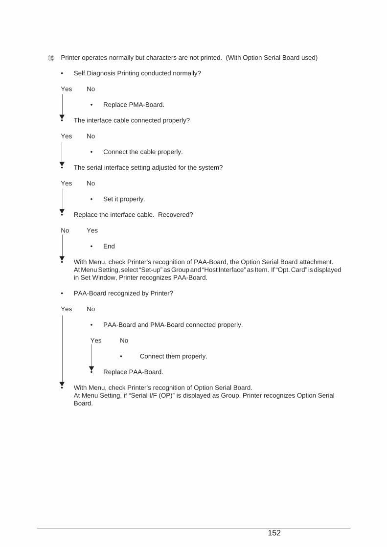
152
F Printer operates normally but characters are not printed. (With Option Serial Board used)
• Self Diagnosis Printing conducted normally?
Yes No
• Replace PMA-Board.
• The interface cable connected properly?
Yes No
• Connect the cable properly.
• The serial interface setting adjusted for the system?
Yes No
• Set it properly.
• Replace the interface cable. Recovered?
No Yes
• End
• With Menu, check Printer’s recognition of PAA-Board, the Option Serial Board attachment.At Menu Setting, select “Set-up” as Group and “Host Interface” as Item. If “Opt. Card” is displayedin Set Window, Printer recognizes PAA-Board.
• PAA-Board recognized by Printer?
Yes No
• PAA-Board and PMA-Board connected properly.
Yes No
• Connect them properly.
• Replace PAA-Board.
• With Menu, check Printer’s recognition of Option Serial Board.At Menu Setting, if “Serial I/F (OP)” is displayed as Group, Printer recognizes Option SerialBoard.
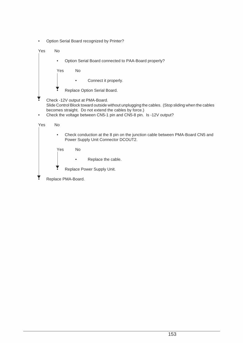
153
• Option Serial Board recognized by Printer?
Yes No
• Option Serial Board connected to PAA-Board properly?
Yes No
• Connect it properly.
• Replace Option Serial Board.
• Check -12V output at PMA-Board.Slide Control Block toward outside without unplugging the cables. (Stop sliding when the cablesbecomes straight. Do not extend the cables by force.)
• Check the voltage between CN5-1 pin and CN5-8 pin. Is -12V output?
Yes No
• Check conduction at the 8 pin on the junction cable between PMA-Board CN5 andPower Supply Unit Connector DCOUT2.
Yes No
• Replace the cable.
• Replace Power Supply Unit.
• Replace PMA-Board.
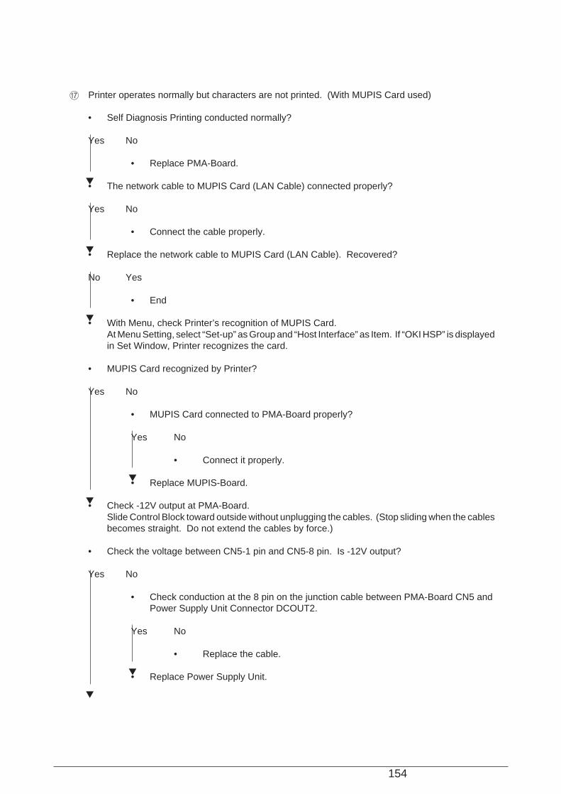
154
G Printer operates normally but characters are not printed. (With MUPIS Card used)
• Self Diagnosis Printing conducted normally?
Yes No
• Replace PMA-Board.
• The network cable to MUPIS Card (LAN Cable) connected properly?
Yes No
• Connect the cable properly.
• Replace the network cable to MUPIS Card (LAN Cable). Recovered?
No Yes
• End
• With Menu, check Printer’s recognition of MUPIS Card.At Menu Setting, select “Set-up” as Group and “Host Interface” as Item. If “OKI HSP” is displayedin Set Window, Printer recognizes the card.
• MUPIS Card recognized by Printer?
Yes No
• MUPIS Card connected to PMA-Board properly?
Yes No
• Connect it properly.
• Replace MUPIS-Board.
• Check -12V output at PMA-Board.Slide Control Block toward outside without unplugging the cables. (Stop sliding when the cablesbecomes straight. Do not extend the cables by force.)
• Check the voltage between CN5-1 pin and CN5-8 pin. Is -12V output?
Yes No
• Check conduction at the 8 pin on the junction cable between PMA-Board CN5 andPower Supply Unit Connector DCOUT2.
Yes No
• Replace the cable.
• Replace Power Supply Unit.
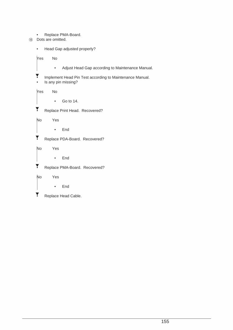
155
• Replace PMA-Board.H Dots are omitted.
• Head Gap adjusted properly?
Yes No
• Adjust Head Gap according to Maintenance Manual.
• Implement Head Pin Test according to Maintenance Manual.• Is any pin missing?
Yes No
• Go to 14.
• Replace Print Head. Recovered?
No Yes
• End
• Replace PDA-Board. Recovered?
No Yes
• End
• Replace PMA-Board. Recovered?
No Yes
• End
• Replace Head Cable.

156
I Images are faint.
• End of Ink Ribbon life?
No Yes
• Replace Ink Ribbon.
• Head Gap adjusted properly?
Yes No
• Adjust it properly.
• Check +44V output at PMA-Board.Slide Control Block toward outside without unplugging the cables. (Stop sliding when the cablesbecomes straight. Do not extend the cables by force.)
• In this state, turn Printer on and check the voltage between CN3 -1 pin and CN3 Pin 12.• More than +38V output?
Yes No
• Replace Power Supply Unit.
• Replace Print Head. Recovered?
No Yes
• End

157
• Replace PDA-Board.J After Carriage works, the Alarm Lamp goes on and “ERROR AUTOGAP” is displayed on LCD.
• Platen operates normally during initialization?
Yes No
• Go to B.
• Adjust Head Gap. Recovered?
No Yes
• End
• Adjust Core Gap. Recovered?
No Yes
• End
• The cables to PRA-Board CN1, CN3 and PGA-Board CN1 connected properly?
Yes No
• Connect the cables properly.
• The cables to PMA-Board CN2, CN6 and CN8 connected properly?
Yes No
• Connect the cables properly.
• The cables to PHA-Board CN1 and CN9 connected properly?
Yes No
• Connect the cables properly.
• Auto-Gap Slit Sensor and Auto-Gap Slit Disc mounted at the proper positions?
Yes No
• Install them properly.
• The gear existing between Auto-Gap Motor and Platen normal? No tooth broken? Nooverloading?
Yes No
• Install the gear properly. Replace it if damaged.• If the Auto-Gap Motor gear is broken, replace the whole Auto-Gap Motor.
• Check Auto-Gap Slit Sensor wave form at PRA-Board. No problem?ø1: Examine between CN3-1 pin and SH4.
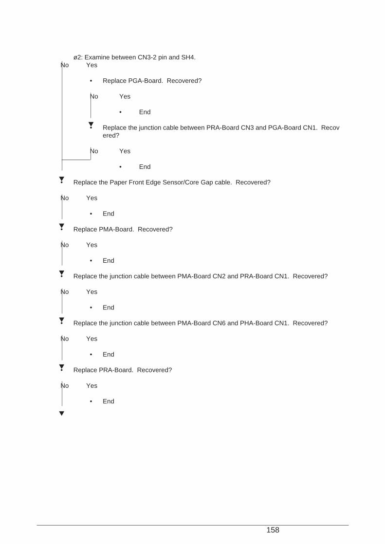
158
ø2: Examine between CN3-2 pin and SH4.No Yes
• Replace PGA-Board. Recovered?
No Yes
• End
• Replace the junction cable between PRA-Board CN3 and PGA-Board CN1. Recovered?
No Yes
• End
• Replace the Paper Front Edge Sensor/Core Gap cable. Recovered?
No Yes
• End
• Replace PMA-Board. Recovered?
No Yes
• End
• Replace the junction cable between PMA-Board CN2 and PRA-Board CN1. Recovered?
No Yes
• End
• Replace the junction cable between PMA-Board CN6 and PHA-Board CN1. Recovered?
No Yes
• End
• Replace PRA-Board. Recovered?
No Yes
• End

159
• Replace PHA-Board.K Paper is set at Tractor, but printing is not conducted in the state of “PAPER END”.
• Intervals between lines occur during printing.• Check ON/OFF operation of the Tractor used (Front or Rear), according to Maintenance Manual.• Normal N/OFF operation?
Yes No
• The cables to PHA-Board CN5 (for Front Tractor) and CN4 (for Rear Tractor)connected properly?
Yes No
• Connect the cables properly.
• Replace the Front Tractor Paper End Switch cable or the Rear Tractor Paper EndSwitch cable which is damaged. Recovered?
No Yes
• End
• Replace the junction cable between PHA-Board CN1 and PMA-Board CN6. Recovered?
No Yes
• End
• Replace PMA-Board. Recovered?
No Yes
• End
• Replace PHA-Board.
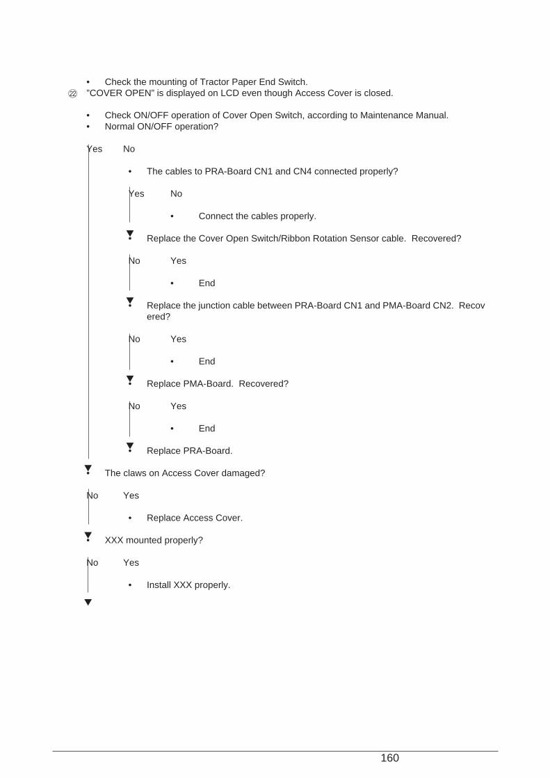
160
• Check the mounting of Tractor Paper End Switch.L ”COVER OPEN” is displayed on LCD even though Access Cover is closed.
• Check ON/OFF operation of Cover Open Switch, according to Maintenance Manual.• Normal ON/OFF operation?
Yes No
• The cables to PRA-Board CN1 and CN4 connected properly?
Yes No
• Connect the cables properly.
• Replace the Cover Open Switch/Ribbon Rotation Sensor cable. Recovered?
No Yes
• End
• Replace the junction cable between PRA-Board CN1 and PMA-Board CN2. Recovered?
No Yes
• End
• Replace PMA-Board. Recovered?
No Yes
• End
• Replace PRA-Board.
• The claws on Access Cover damaged?
No Yes
• Replace Access Cover.
• XXX mounted properly?
No Yes
• Install XXX properly.

161
• Check the mounting of Cover Open Switch.M Pressing Operation Panel Switches does not make Printer operate. (after normal initialization)
• The cable between POA-Board CN1 and PHA-Board CN12 connected properly?
Yes No
• Connect the cable properly.
• Check conduction at the junction cable between POA-Board CN1 and PHA-Board CN12.• Normal conduction?
Yes No
• Replace the junction cable.
• Replace POA-Board. Recovered?
No Yes
• End
• Replace the junction cable between PMA-Board CN6 and PHA-Board CN1. Recovered?
No Yes
• End
• Replace PHA-Board. Recovered?
No Yes
• End
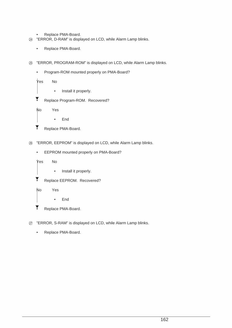
162
• Replace PMA-Board.N ”ERROR, D-RAM” is displayed on LCD, while Alarm Lamp blinks.
• Replace PMA-Board.
O ”ERROR, PROGRAM-ROM” is displayed on LCD, while Alarm Lamp blinks.
• Program-ROM mounted properly on PMA-Board?
Yes No
• Install it properly.
• Replace Program-ROM. Recovered?
No Yes
• End
• Replace PMA-Board.
P ”ERROR, EEPROM” is displayed on LCD, while Alarm Lamp blinks.
• EEPROM mounted properly on PMA-Board?
Yes No
• Install it properly.
• Replace EEPROM. Recovered?
No Yes
• End
• Replace PMA-Board.
Q ”ERROR, S-RAM” is displayed on LCD, while Alarm Lamp blinks.
• Replace PMA-Board.

163
R ”ERROR, CG-ROM” is displayed on LCD, while Alarm Lamp blinks.
• CG-ROM mounted properly on PMA-Board?
Yes No
• Install it properly.
• Replace CG-ROM. Recovered?
No Yes
• End
• Replace PMA-Board.
S ”ERROR, CENTERING” is displayed on LCD, while Alarm Lamp blinks.
• Go to 4.
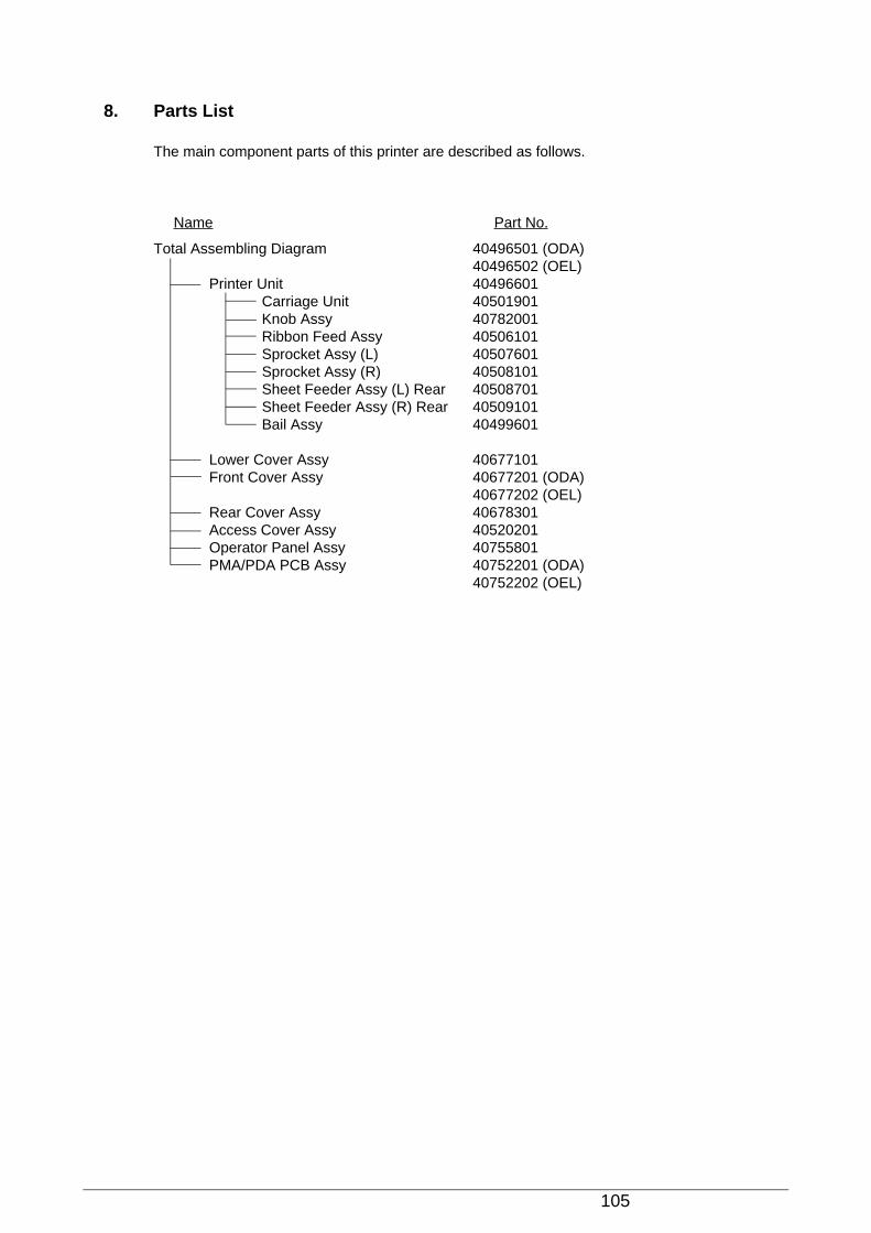
105
8. Parts List
The main component parts of this printer are described as follows.
Total Assembling Diagram 40496501 (ODA)40496502 (OEL)
Printer Unit 40496601Carriage Unit 40501901Knob Assy 40782001Ribbon Feed Assy 40506101Sprocket Assy (L) 40507601Sprocket Assy (R) 40508101Sheet Feeder Assy (L) Rear 40508701Sheet Feeder Assy (R) Rear 40509101Bail Assy 40499601
Lower Cover Assy 40677101Front Cover Assy 40677201 (ODA)
40677202 (OEL)Rear Cover Assy 40678301Access Cover Assy 40520201Operator Panel Assy 40755801PMA/PDA PCB Assy 40752201 (ODA)
40752202 (OEL)
Name Part No.
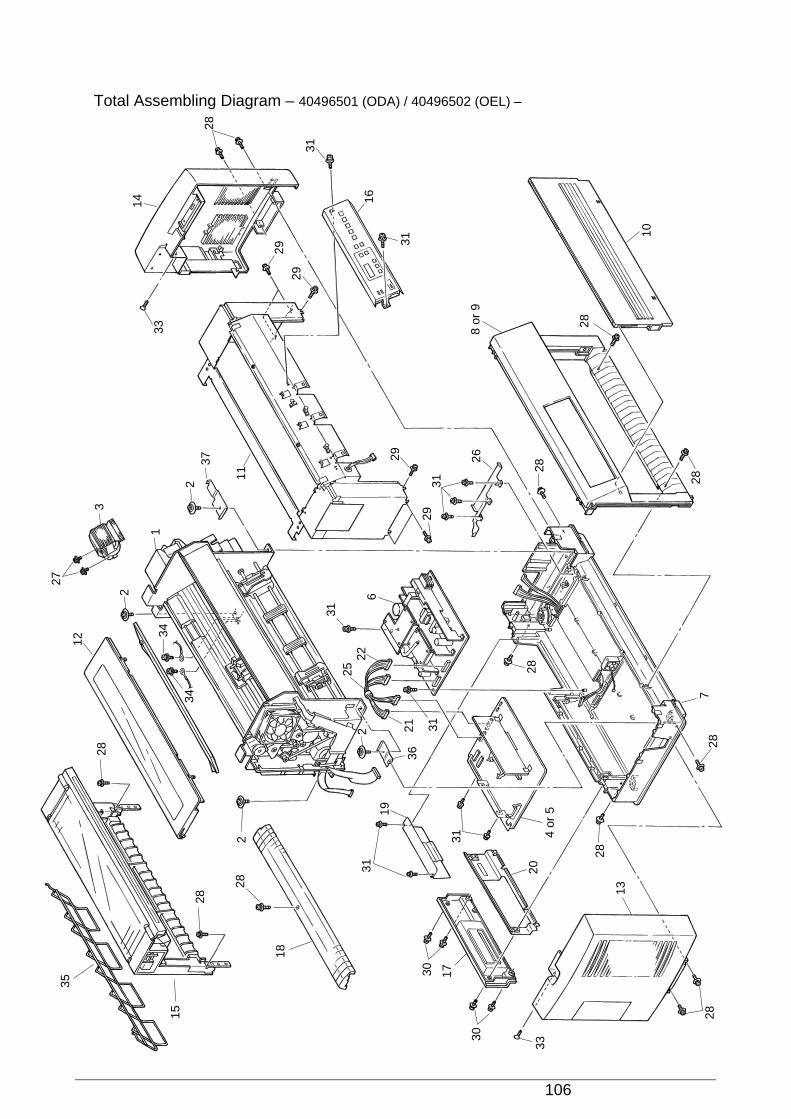
106
Total Assembling Diagram – 40496501 (ODA) / 40496502 (OEL) –
35
28
12
3
33
14
28
29
16
29
1
2
27
28
282
2
36
31
31
19
31
30 17
204
or 5
21
34
34
18
15
2
37
11
31
31
8 or
9
28
10
2828
28
28
13
28
3125
226
29 26
28
7
3129
30
33
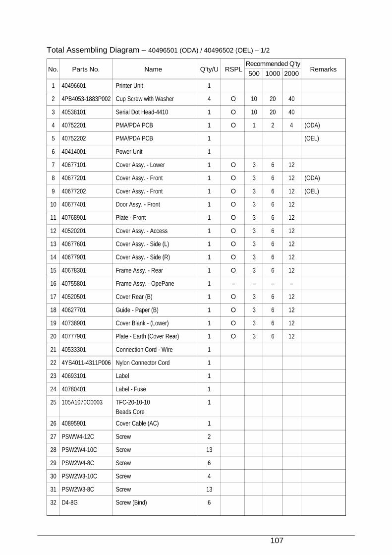
107
1 40496601 Printer Unit 1
2 4PB4053-1883P002 Cup Screw with Washer 4 O 10 20 40
3 40538101 Serial Dot Head-4410 1 O 10 20 40
4 40752201 PMA/PDA PCB 1 O 1 2 4 (ODA)
5 40752202 PMA/PDA PCB 1 (OEL)
6 40414001 Power Unit 1
7 40677101 Cover Assy. - Lower 1 O 3 6 12
8 40677201 Cover Assy. - Front 1 O 3 6 12 (ODA)
9 40677202 Cover Assy. - Front 1 O 3 6 12 (OEL)
10 40677401 Door Assy. - Front 1 O 3 6 12
11 40768901 Plate - Front 1 O 3 6 12
12 40520201 Cover Assy. - Access 1 O 3 6 12
13 40677601 Cover Assy. - Side (L) 1 O 3 6 12
14 40677901 Cover Assy. - Side (R) 1 O 3 6 12
15 40678301 Frame Assy. - Rear 1 O 3 6 12
16 40755801 Frame Assy. - OpePane 1 – – – –
17 40520501 Cover Rear (B) 1 O 3 6 12
18 40627701 Guide - Paper (B) 1 O 3 6 12
19 40738901 Cover Blank - (Lower) 1 O 3 6 12
20 40777901 Plate - Earth (Cover Rear) 1 O 3 6 12
21 40533301 Connection Cord - Wire 1
22 4YS4011-4311P006 Nylon Connector Cord 1
23 40693101 Label 1
24 40780401 Label - Fuse 1
25 105A1070C0003 TFC-20-10-10 1Beads Core
26 40895901 Cover Cable (AC) 1
27 PSWW4-12C Screw 2
28 PSW2W4-10C Screw 13
29 PSW2W4-8C Screw 6
30 PSW2W3-10C Screw 4
31 PSW2W3-8C Screw 13
32 D4-8G Screw (Bind) 6
Total Assembling Diagram – 40496501 (ODA) / 40496502 (OEL) – 1/2
No. Parts No. Name Q’ty/U RSPLRecommended Q’ty
Remarks500 1000 2000
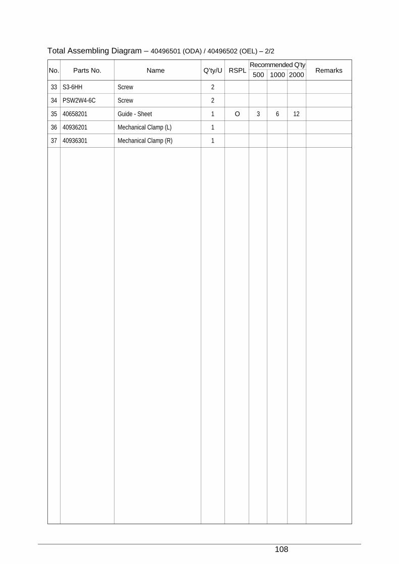
108
33 S3-6HH Screw 2
34 PSW2W4-6C Screw 2
35 40658201 Guide - Sheet 1 O 3 6 12
36 40936201 Mechanical Clamp (L) 1
37 40936301 Mechanical Clamp (R) 1
Total Assembling Diagram – 40496501 (ODA) / 40496502 (OEL) – 2/2
No. Parts No. Name Q’ty/U RSPLRecommended Q’ty
Remarks500 1000 2000
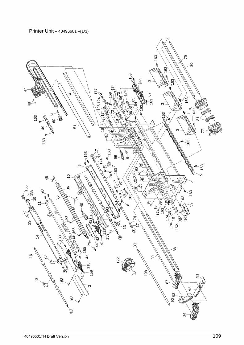
40496501TH Draft Version 109
Printer Unit – 40496601 –(1/3)13
163
163
215
911
843
41
42
180
120
119
180
163
163
4544
4218
0
4143
7115
9118
1717
416
3
163
163
138
8
8
7
716
3
163
174
7217
6
163
7
9
68 9
6970
122
108
86
9093
87
39
152
170
1817
4174
163
62
591
5
3
77
7880
79
67
83
9697 16
3
163
163
163
163
163
8485
7396
174
98
7318
7272
1594
51
124
177
159
81
3
163
163
163
163
163
163
163
123
174
174
174
7273
18
6160
4916
3
163
4847
3
75
18
88
92
91
16 23
2319
1116
3
35
3610
40
37
45
155
158
14
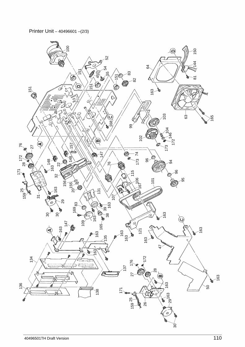
40496501TH Draft Version 110
Printer Unit – 40496601 –(2/3)
136
134
147
30 38
121
10713
1
39
31
30
159
2517
117
228
76 27
135
171
138
25
28
95
163
163
163
163
163
163
163
163
96
96
101
115
76
147
157
106
167
94
63
165
8114
415
0
64
146
172
173
173
7410
2
168
9982
163
83
151
151
151
151
5554
45
52
100
104
103
2717
6
137
172
159 26
2930
50
47
163
163
165
163
163
163
163
163 10
9
169
83
29
20
322214
8 148
155
156

40496501TH Draft Version 111
Printer Unit – 40496601 –(3/3)
113
112
3030
29
140
148
163
163
163
163
148
139
163
114
2117
3
163
129
3320 17
3 19
111
169
163 16
3
163
53
163
165
2111
083
15113
2
38 115
117
160
148
161
56
57
154
116
45 5516
8
143
143
144
181
145
56
177
127
124
12916
3
163
128
168
126
125
180
163
130
147
168
168
163
65
6616
6
166
153
147
58
133
167
177
142
168
14116
7
167
39
156
122
24

112
1 40799801 Flame - Main 1
2 40498401 Plate - Rear 1
3 40537701 Guide - Paper 3
4 40498501 Beam - Slide 1
5 40498601 Front Guide - Sheet (U) A 1
6 40498701 Front Guide - Paper (U) B 1
7 40498801 Spring - Pressure 3 O 3 6 12
8 3PP4053-3795P001 Pressure Roller Piece 3 O 3 6 12
9 4PB4044-1358P002 Stopper 2 O 3 6 12
10 40501601 Sheet Guide Front (L) Assy 1
11 40501701 Sheet Guide Rear (L) Assy 1
12
13 40791901 Guide - Shaft Roller 2
14 40499601 Bail Assy 1 O 3 6 12
15 40745501 Screw - Stud 1 O 3 6 12
16 40507501 Feed Roller Shaft RL 1
17 4PB4035-4456P001 Bearing - Metal 2 O 3 6 12
18 LP-6418-13 Ball Bearing RSF (12*8 W=3.5) 4 O 3 6 12
19 40608401 Drive Gear C 1 O 3 6 12
20 40608301 Drive Gear B 3 O 3 6 12
21 4PP3520-1306P001 Idle Gear 3 O 3 6 12
22 40555001 Bearing - Metal (Bail) 2 O 3 6 12
23 40791801 Bail Arm - Spring 2
24 40609201 Bail Gear Bracket Assy 1 O 3 6 12
25 40534201 Connection Cord - Wire 1
26 40510501 Change Motor Bracket Assy 1
27 4PP4122-1285P001 Gear (Z19-52) 2
28 4LR-200494 Brake Gear (BC) 2 O 3 6 12
29 40472401 Change Motor 3
30 4PB3529-5116P001 Tapping Screw 6
31 40608501 Bail Motor Bracket Assy 1 O 3 6 12
32 40511801 Lever - Bail Lift (L) 1 O 3 6 12
33 40511901 Lever - Bail Lift (R) 1 O 3 6 12
Printer Unit – 40496601 – 1/6
No. Parts No. Name Q’ty/U RSPLRecommended Q’ty
Remarks500 1000 2000
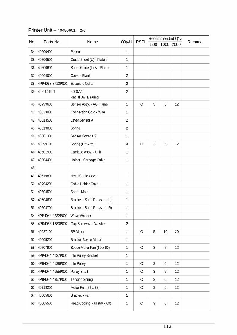
113
Printer Unit – 40496601 – 2/6
No. Parts No. Name Q’ty/U RSPLRecommended Q’ty
Remarks500 1000 2000
34 40500401 Platen 1
35 40500501 Guide Sheet (U) - Platen 1
36 40500601 Sheet Guide (L) A - Platen 1
37 40564001 Cover - Blank 2
38 4PP4053-3712P001 Eccentric Collar 2
39 4LP-6419-1 6000ZZ 2Radial Ball Bearing
40 40799601 Sensor Assy. - AG Flame 1 O 3 6 12
41 40533901 Connection Cord - Wire 1
42 40513501 Lever Sensor A 2
43 40513801 Spring 2
44 40501301 Sensor Cover AG 1
45 40099101 Spring (Lift Arm) 4 O 3 6 12
46 40501901 Carriage Assy. - Unit 1
47 40504401 Holder - Carriage Cable 1
48
49 40619801 Head Cable Cover 1
50 40794201 Cable Holder Cover 1
51 40504501 Shaft - Main 1
52 40504601 Bracket - Shaft Pressure (L) 1
53 40504701 Bracket - Shaft Pressure (R) 1
54 4PP4044-4232P001 Wave Washer 1
55 4PB4053-1883P002 Cup Screw with Washer 2
56 40627101 SP Motor 1 O 5 10 20
57 40505201 Bracket Space Motor 1
58 40507901 Space Motor Fan (60 x 60) 1 O 3 6 12
59 4PP4044-4137P001 Idle Pulley Bracket 1
60 4PB4044-4138P001 Idle Pulley 1 O 3 6 12
61 4PP4044-4155P001 Pulley Shaft 1 O 3 6 12
62 4PB4044-4357P001 Tension Spring 1 O 3 6 12
63 40719201 Motor Fan (92 x 92) 1 O 3 6 12
64 40505601 Bracket - Fan 1
65 40505501 Head Cooling Fan (60 x 60) 1 O 3 6 12
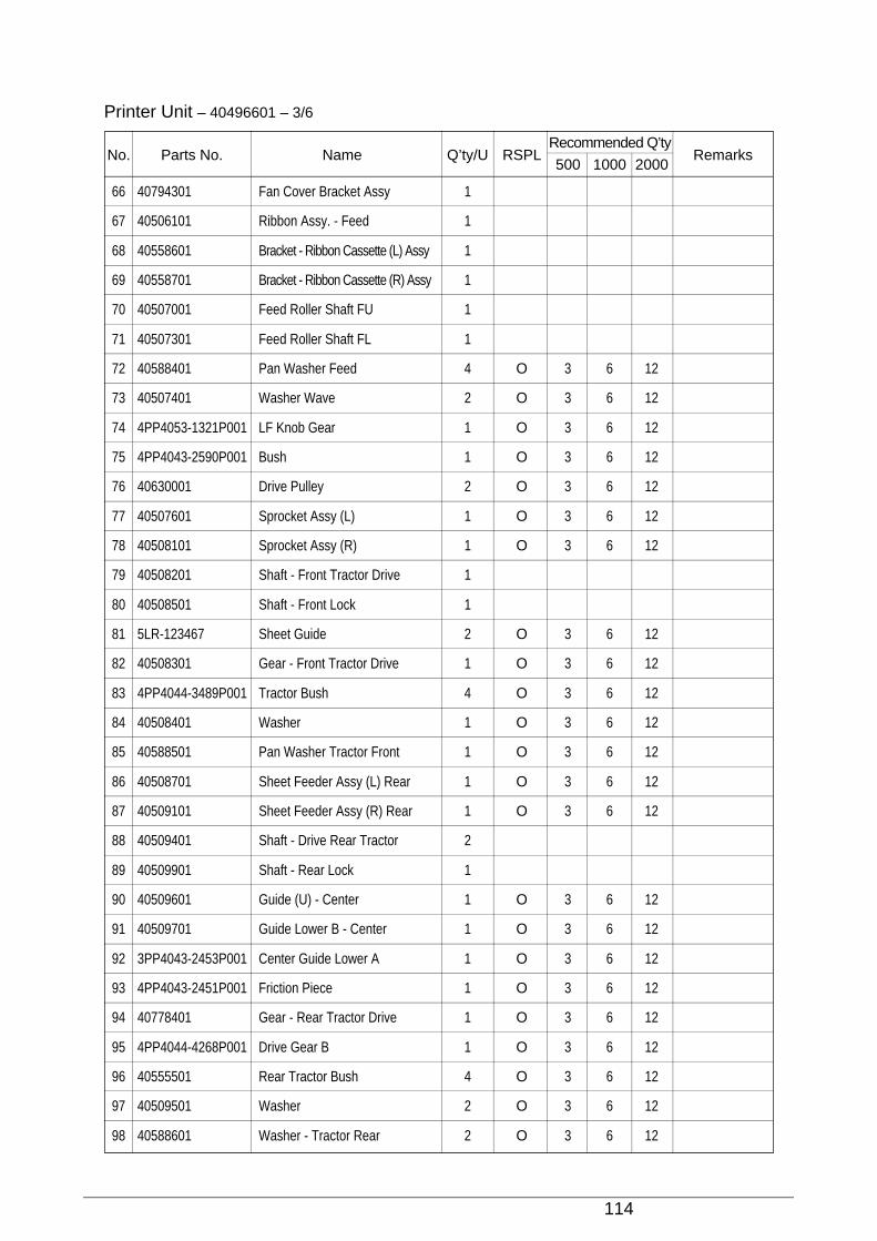
114
Printer Unit – 40496601 – 3/6
No. Parts No. Name Q’ty/U RSPLRecommended Q’ty
Remarks500 1000 2000
66 40794301 Fan Cover Bracket Assy 1
67 40506101 Ribbon Assy. - Feed 1
68 40558601 Bracket - Ribbon Cassette (L) Assy 1
69 40558701 Bracket - Ribbon Cassette (R) Assy 1
70 40507001 Feed Roller Shaft FU 1
71 40507301 Feed Roller Shaft FL 1
72 40588401 Pan Washer Feed 4 O 3 6 12
73 40507401 Washer Wave 2 O 3 6 12
74 4PP4053-1321P001 LF Knob Gear 1 O 3 6 12
75 4PP4043-2590P001 Bush 1 O 3 6 12
76 40630001 Drive Pulley 2 O 3 6 12
77 40507601 Sprocket Assy (L) 1 O 3 6 12
78 40508101 Sprocket Assy (R) 1 O 3 6 12
79 40508201 Shaft - Front Tractor Drive 1
80 40508501 Shaft - Front Lock 1
81 5LR-123467 Sheet Guide 2 O 3 6 12
82 40508301 Gear - Front Tractor Drive 1 O 3 6 12
83 4PP4044-3489P001 Tractor Bush 4 O 3 6 12
84 40508401 Washer 1 O 3 6 12
85 40588501 Pan Washer Tractor Front 1 O 3 6 12
86 40508701 Sheet Feeder Assy (L) Rear 1 O 3 6 12
87 40509101 Sheet Feeder Assy (R) Rear 1 O 3 6 12
88 40509401 Shaft - Drive Rear Tractor 2
89 40509901 Shaft - Rear Lock 1
90 40509601 Guide (U) - Center 1 O 3 6 12
91 40509701 Guide Lower B - Center 1 O 3 6 12
92 3PP4043-2453P001 Center Guide Lower A 1 O 3 6 12
93 4PP4043-2451P001 Friction Piece 1 O 3 6 12
94 40778401 Gear - Rear Tractor Drive 1 O 3 6 12
95 4PP4044-4268P001 Drive Gear B 1 O 3 6 12
96 40555501 Rear Tractor Bush 4 O 3 6 12
97 40509501 Washer 2 O 3 6 12
98 40588601 Washer - Tractor Rear 2 O 3 6 12
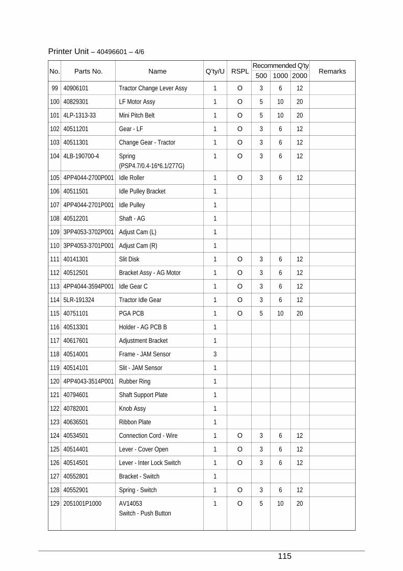
115
99 40906101 Tractor Change Lever Assy 1 O 3 6 12
100 40829301 LF Motor Assy 1 O 5 10 20
101 4LP-1313-33 Mini Pitch Belt 1 O 5 10 20
102 40511201 Gear - LF 1 O 3 6 12
103 40511301 Change Gear - Tractor 1 O 3 6 12
104 4LB-190700-4 Spring 1 O 3 6 12(PSP4.7/0.4-16*6.1/277G)
105 4PP4044-2700P001 Idle Roller 1 O 3 6 12
106 40511501 Idle Pulley Bracket 1
107 4PP4044-2701P001 Idle Pulley 1
108 40512201 Shaft - AG 1
109 3PP4053-3702P001 Adjust Cam (L) 1
110 3PP4053-3701P001 Adjust Cam (R) 1
111 40141301 Slit Disk 1 O 3 6 12
112 40512501 Bracket Assy - AG Motor 1 O 3 6 12
113 4PP4044-3594P001 Idle Gear C 1 O 3 6 12
114 5LR-191324 Tractor Idle Gear 1 O 3 6 12
115 40751101 PGA PCB 1 O 5 10 20
116 40513301 Holder - AG PCB B 1
117 40617601 Adjustment Bracket 1
118 40514001 Frame - JAM Sensor 3
119 40514101 Slit - JAM Sensor 1
120 4PP4043-3514P001 Rubber Ring 1
121 40794601 Shaft Support Plate 1
122 40782001 Knob Assy 1
123 40636501 Ribbon Plate 1
124 40534501 Connection Cord - Wire 1 O 3 6 12
125 40514401 Lever - Cover Open 1 O 3 6 12
126 40514501 Lever - Inter Lock Switch 1 O 3 6 12
127 40552801 Bracket - Switch 1
128 40552901 Spring - Switch 1 O 3 6 12
129 2051001P1000 AV14053 1 O 5 10 20Switch - Push Button
Printer Unit – 40496601 – 4/6
No. Parts No. Name Q’ty/U RSPLRecommended Q’ty
Remarks500 1000 2000
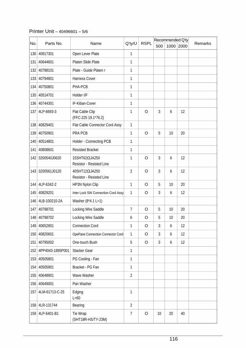
116
130 40917301 Open Lever Plate 1
131 40644601 Platen Slide Plate 1
132 40788101 Plate - Guide Platen r 1
133 40794801 Harness Cover 1
134 40750801 PHA-PCB 1
135 40514701 Holder I/F 1
136 40744301 IF-Kiban-Cover 1
137 4LP-6693-3 Flat Cable Clip 1 O 3 6 12
(FFC-225 19.1*76.2)
138 40829401 Flat Cable Connector Cord Assy 1
139 40750901 PRA PCB 1 O 5 10 20
140 40514801 Holder - Connecting PCB 1
141 40808601 Resisted Bracket 1
142 3200540J0620 15SHT62ΩJA250 1 O 3 6 12Resistor - Resisted Line
143 3200561J0120 40SHT12ΩJA250 2 O 3 6 12
Resistor - Resisted Line
144 4LP-6342-2 HP3N Nylon Clip 1 O 5 10 20
145 40829201 Inter Lock SW Connection Cord Assy 1 O 3 6 12
146 4LB-100210-2A Washer (8*4.1 L=1)
147 40798701 Locking Wire Saddle 7 O 5 10 20
148 40798702 Locking Wire Saddle 6 O 5 10 20
149 40652901 Connection Cord 1 O 3 6 12
150 40820601 OpePane Connection Connector Cord 1 O 3 6 12
151 40795002 One-touch Bush 5 O 3 6 12
152 4PP4043-1895P001 Stacker Gear 1
153 40505801 PG Cooling - Fan 1
154 40505901 Bracket - PG Fan 1
155 40648901 Wave Washer 2
156 40649001 Pan Washer
157 4LM-61713-C-25 Edging 1L=60
158 4LR-131744 Bearing 2
159 4LP-6401-B1 Tie Wrap 7 O 10 20 40(SHT18R-HS/TY-23M)
Printer Unit – 40496601 – 5/6
No. Parts No. Name Q’ty/U RSPLRecommended Q’ty
Remarks500 1000 2000
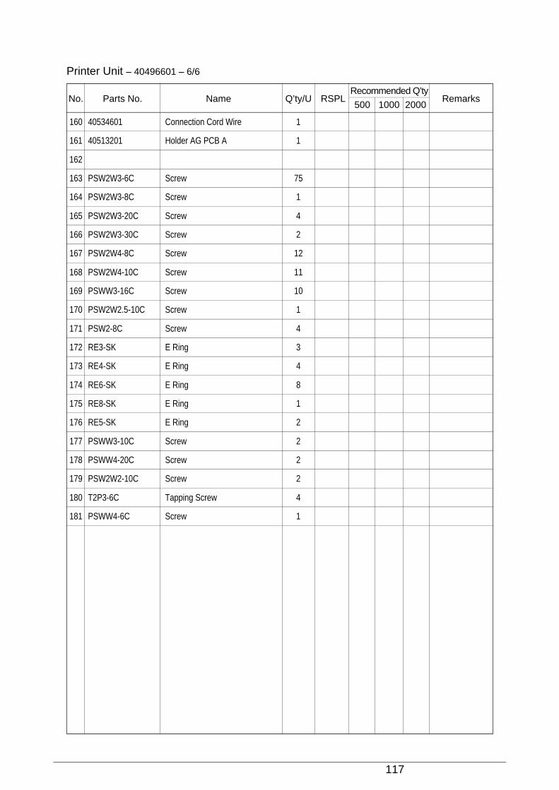
117
Printer Unit – 40496601 – 6/6
No. Parts No. Name Q’ty/U RSPLRecommended Q’ty
Remarks500 1000 2000
160 40534601 Connection Cord Wire 1
161 40513201 Holder AG PCB A 1
162
163 PSW2W3-6C Screw 75
164 PSW2W3-8C Screw 1
165 PSW2W3-20C Screw 4
166 PSW2W3-30C Screw 2
167 PSW2W4-8C Screw 12
168 PSW2W4-10C Screw 11
169 PSWW3-16C Screw 10
170 PSW2W2.5-10C Screw 1
171 PSW2-8C Screw 4
172 RE3-SK E Ring 3
173 RE4-SK E Ring 4
174 RE6-SK E Ring 8
175 RE8-SK E Ring 1
176 RE5-SK E Ring 2
177 PSWW3-10C Screw 2
178 PSWW4-20C Screw 2
179 PSW2W2-10C Screw 2
180 T2P3-6C Tapping Screw 4
181 PSWW4-6C Screw 1
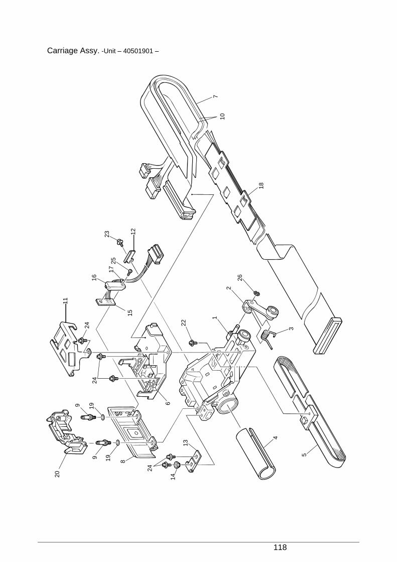
118
Carriage Assy. -Unit – 40501901 –20
9 19
1924
24
11
9
8
24
14
13
5
4
3
26
2
1
22
710
18
17
16
2523 12
15
6
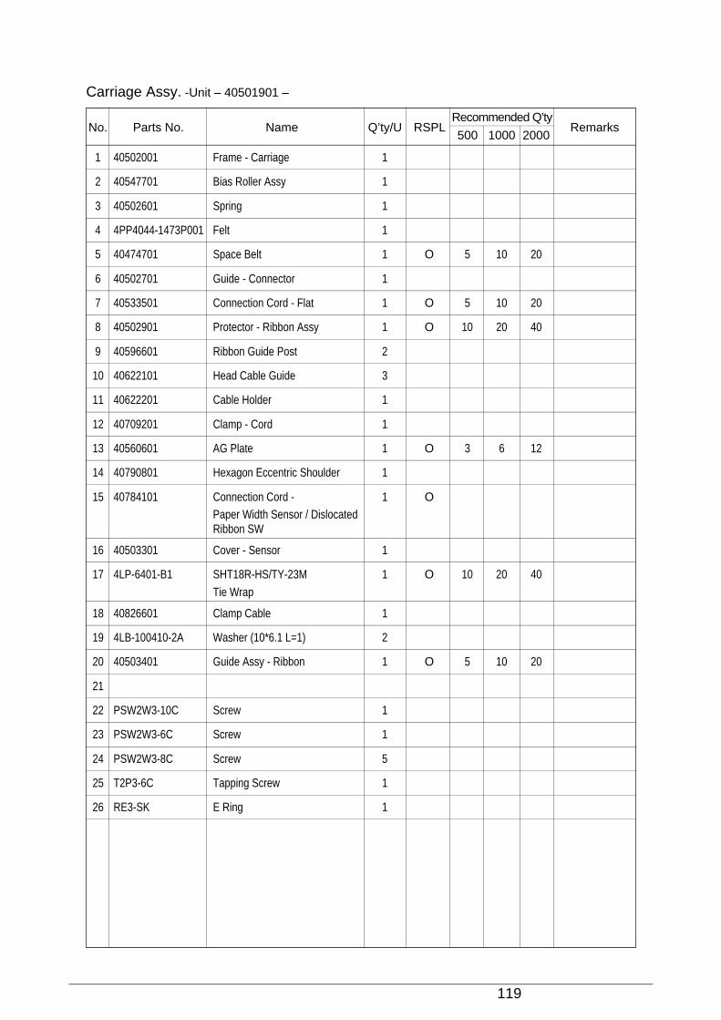
119
Carriage Assy. -Unit – 40501901 –
No. Parts No. Name Q’ty/U RSPLRecommended Q’ty
Remarks500 1000 2000
1 40502001 Frame - Carriage 1
2 40547701 Bias Roller Assy 1
3 40502601 Spring 1
4 4PP4044-1473P001 Felt 1
5 40474701 Space Belt 1 O 5 10 20
6 40502701 Guide - Connector 1
7 40533501 Connection Cord - Flat 1 O 5 10 20
8 40502901 Protector - Ribbon Assy 1 O 10 20 40
9 40596601 Ribbon Guide Post 2
10 40622101 Head Cable Guide 3
11 40622201 Cable Holder 1
12 40709201 Clamp - Cord 1
13 40560601 AG Plate 1 O 3 6 12
14 40790801 Hexagon Eccentric Shoulder 1
15 40784101 Connection Cord - 1 OPaper Width Sensor / DislocatedRibbon SW
16 40503301 Cover - Sensor 1
17 4LP-6401-B1 SHT18R-HS/TY-23M 1 O 10 20 40
Tie Wrap
18 40826601 Clamp Cable 1
19 4LB-100410-2A Washer (10*6.1 L=1) 2
20 40503401 Guide Assy - Ribbon 1 O 5 10 20
21
22 PSW2W3-10C Screw 1
23 PSW2W3-6C Screw 1
24 PSW2W3-8C Screw 5
25 T2P3-6C Tapping Screw 1
26 RE3-SK E Ring 1
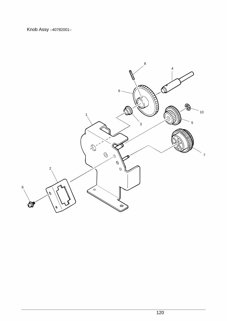
120
Knob Assy –40782001–
84
6
3 5
10
7
1
2
9
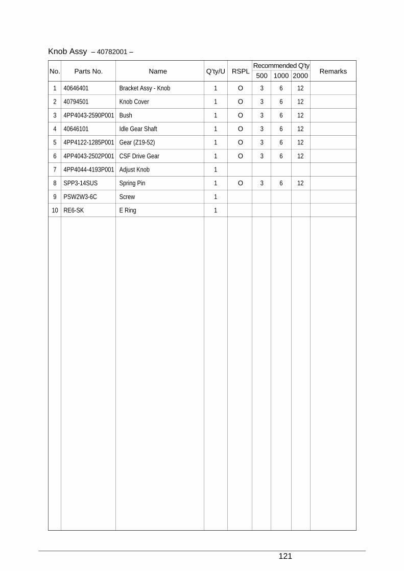
121
Knob Assy – 40782001 –
No. Parts No. Name Q’ty/U RSPLRecommended Q’ty
Remarks500 1000 2000
1 40646401 Bracket Assy - Knob 1 O 3 6 12
2 40794501 Knob Cover 1 O 3 6 12
3 4PP4043-2590P001 Bush 1 O 3 6 12
4 40646101 Idle Gear Shaft 1 O 3 6 12
5 4PP4122-1285P001 Gear (Z19-52) 1 O 3 6 12
6 4PP4043-2502P001 CSF Drive Gear 1 O 3 6 12
7 4PP4044-4193P001 Adjust Knob 1
8 SPP3-14SUS Spring Pin 1 O 3 6 12
9 PSW2W3-6C Screw 1
10 RE6-SK E Ring 1
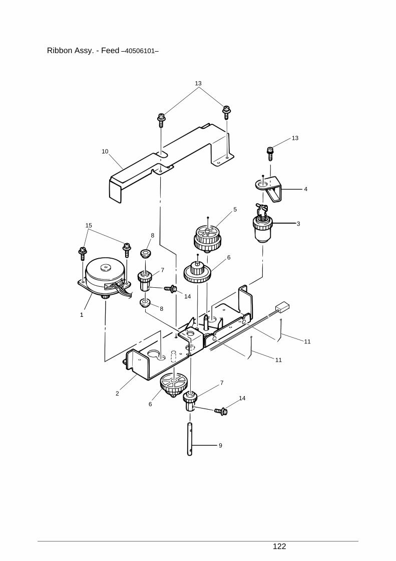
122
Ribbon Assy. - Feed –40506101–
1
15
8
7
8
14
6
5
10
13
3
4
13
2
6
7
14
9
11
11
1

123
Ribbon Assy. - Feed – 40506101 –
No. Parts No. Name Q’ty/U RSPLRecommended Q’ty
Remarks500 1000 2000
1 40458201 Motor - Ribbon 1 O
2 40506201 Frame Assy. - Ribbon Feed 1
3 4PP4044-4161G001 Ribbon Drive Gear Assy 1
4 4PP4044-4347P001 Drive Gear Bracket 1
5 4PP4044-4172P001 Idle Gear 1
6 4PP4044-4173P001 Ribbon Feed Gear 2
7 4PP4043-1895P001 Stacker Gear 2
8 4PP4043-2590P001 Bush 2
9 40631401 Shaft - Idle 1
10 40631201 Holder - Ribbon Bracket 1
11 4LP-6401-B1 SHT18R-HS/TY-23M 2
Tie Wrap
12
13 PSW2W3-6C Screw 3
14 PSSWW2.5-8C Screw 2
15 PSWW3-6C Screw 2

124
Sprocket Assy (L) – 40507601 –
3
2
5
6
119
19
7
4
2110
8
9
20
18
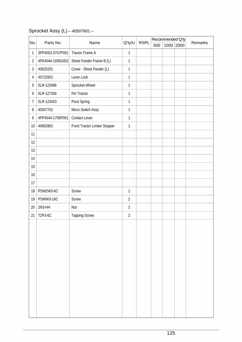
125
Sprocket Assy (L) – 40507601 –
No. Parts No. Name Q’ty/U RSPLRecommended Q’ty
Remarks500 1000 2000
1 3PP4053-3747P001 Tractor Frame A 1
2 4PK4044-1936G001 Sheet Feeder Frame B (L) 1
3 40625201 Cover - Sheet Feeder (L) 1
4 40722601 Lever Lock 1
5 5LR-123486 Sprocket Wheel 1
6 5LR-127356 Pin Tractor 1
7 5LR-123453 Pivot Spring 1
8 40507701 Micro Switch Assy 1
9 4PP4044-1795P001 Contact Lever 1
10 40662801 Front Tractor Limiter Stopper 1
11
12
13
14
15
16
17
18 PSW2W3-6C Screw 1
19 PSWW3-16C Screw 2
20 2N3-HH Nut 2
21 T2P3-6C Tapping Screw 2
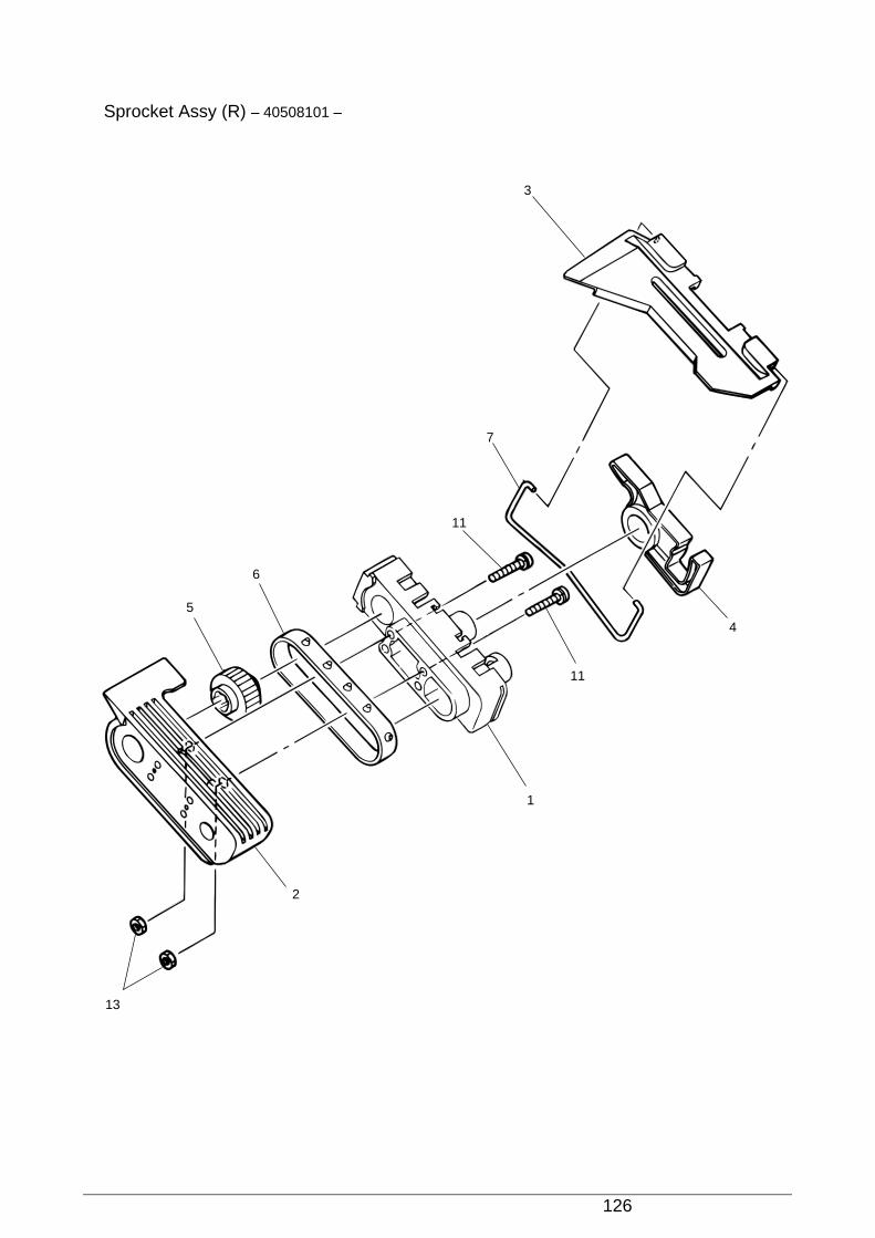
126
Sprocket Assy (R) – 40508101 –
3
7
11
11
1
6
5
2
13
4
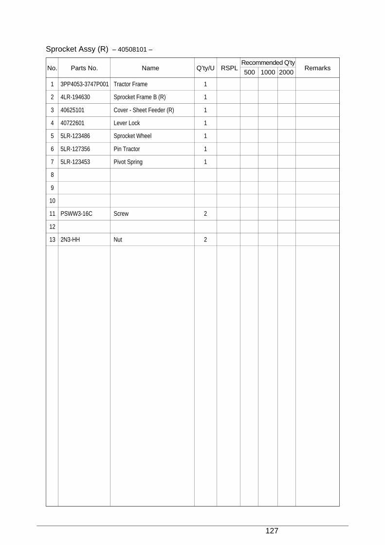
127
Sprocket Assy (R) – 40508101 –
No. Parts No. Name Q’ty/U RSPLRecommended Q’ty
Remarks500 1000 2000
1 3PP4053-3747P001 Tractor Frame 1
2 4LR-194630 Sprocket Frame B (R) 1
3 40625101 Cover - Sheet Feeder (R) 1
4 40722601 Lever Lock 1
5 5LR-123486 Sprocket Wheel 1
6 5LR-127356 Pin Tractor 1
7 5LR-123453 Pivot Spring 1
8
9
10
11 PSWW3-16C Screw 2
12
13 2N3-HH Nut 2

128
Sheet Feeder Assy (L) Rear – 40508701 –
9
10
4
16
212
5
6
7
1311
3
81
14
10
15
16
Pin
Pro
truc
sion
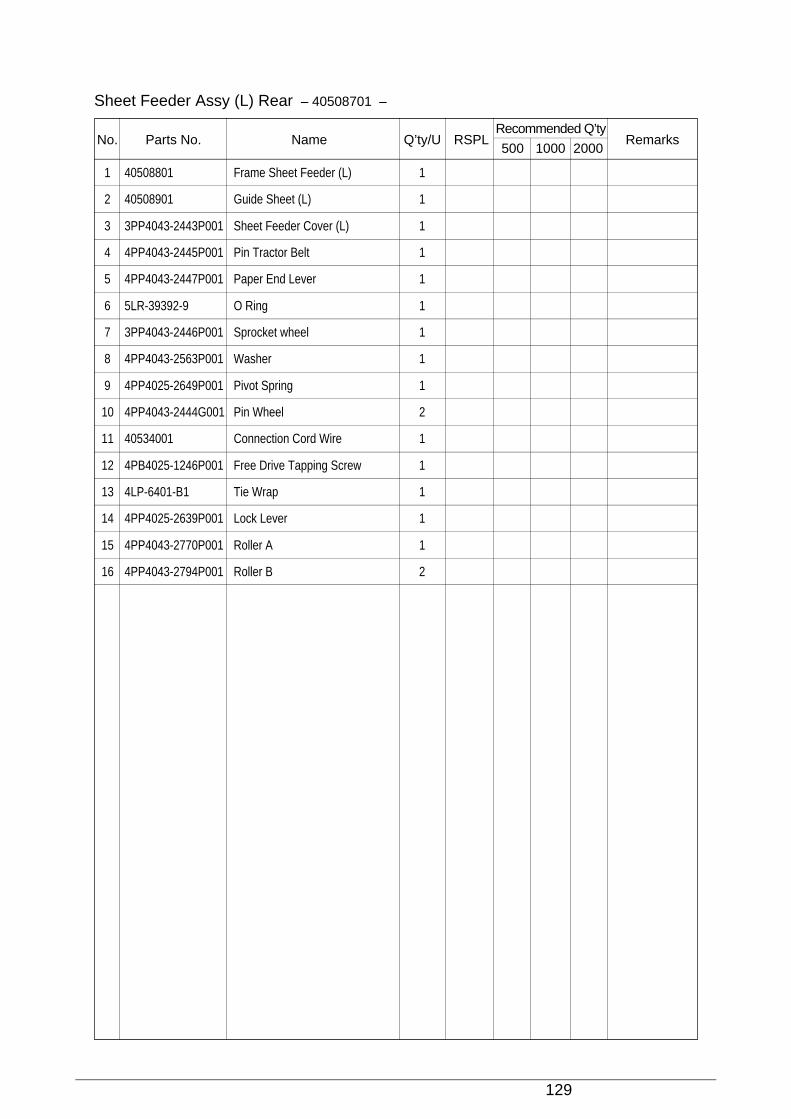
129
Sheet Feeder Assy (L) Rear – 40508701 –
No. Parts No. Name Q’ty/U RSPLRecommended Q’ty
Remarks500 1000 2000
1 40508801 Frame Sheet Feeder (L) 1
2 40508901 Guide Sheet (L) 1
3 3PP4043-2443P001 Sheet Feeder Cover (L) 1
4 4PP4043-2445P001 Pin Tractor Belt 1
5 4PP4043-2447P001 Paper End Lever 1
6 5LR-39392-9 O Ring 1
7 3PP4043-2446P001 Sprocket wheel 1
8 4PP4043-2563P001 Washer 1
9 4PP4025-2649P001 Pivot Spring 1
10 4PP4043-2444G001 Pin Wheel 2
11 40534001 Connection Cord Wire 1
12 4PB4025-1246P001 Free Drive Tapping Screw 1
13 4LP-6401-B1 Tie Wrap 1
14 4PP4025-2639P001 Lock Lever 1
15 4PP4043-2770P001 Roller A 1
16 4PP4043-2794P001 Roller B 2
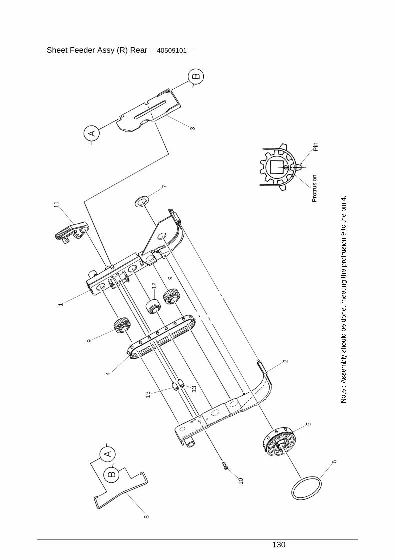
130
Sheet Feeder Assy (R) Rear – 40509101 –
8
111
9
4
13
13
10
6
5
2
9
12
7
3
Pin
Pro
trus
ion
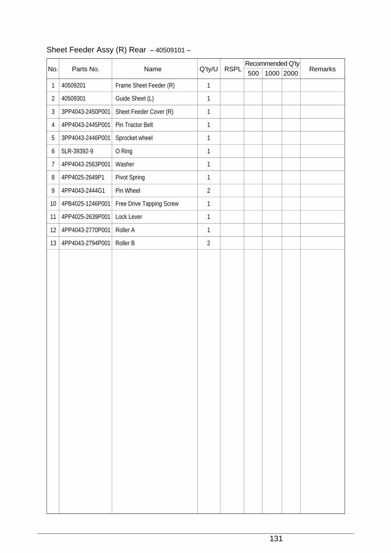
131
1 40509201 Frame Sheet Feeder (R) 1
2 40509301 Guide Sheet (L) 1
3 3PP4043-2450P001 Sheet Feeder Cover (R) 1
4 4PP4043-2445P001 Pin Tractor Belt 1
5 3PP4043-2446P001 Sprocket wheel 1
6 5LR-39392-9 O Ring 1
7 4PP4043-2563P001 Washer 1
8 4PP4025-2649P1 Pivot Spring 1
9 4PP4043-2444G1 Pin Wheel 2
10 4PB4025-1246P001 Free Drive Tapping Screw 1
11 4PP4025-2639P001 Lock Lever 1
12 4PP4043-2770P001 Roller A 1
13 4PP4043-2794P001 Roller B 2
Sheet Feeder Assy (R) Rear – 40509101 –
No. Parts No. Name Q’ty/U RSPLRecommended Q’ty
Remarks500 1000 2000
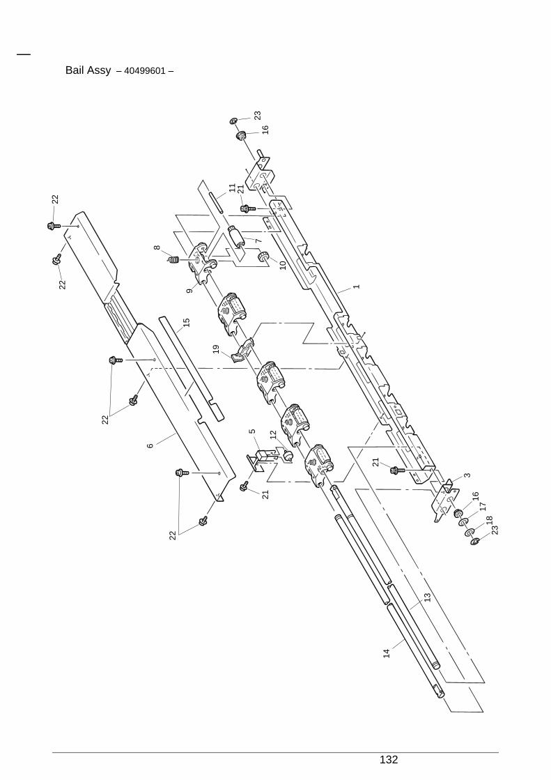
132
Bail Assy – 40499601 –
22
22
2222
8
11 21
2316
1
21
316
1718
13
14
23
7
10
19
5
2112
915
6
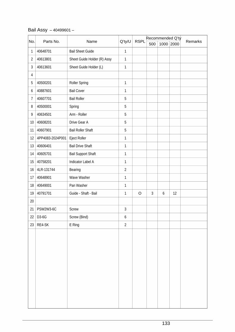
133
1 40648701 Bail Sheet Guide 1
2 40613801 Sheet Guide Holder (R) Assy 1
3 40613601 Sheet Guide Holder (L) 1
4
5 40500201 Roller Spring 1
6 40887601 Bail Cover 1
7 40607701 Bail Roller 5
8 40500001 Spring 5
9 40634501 Arm - Roller 5
10 40608201 Drive Gear A 5
11 40607901 Bail Roller Shaft 5
12 4PP4083-2024P001 Eject Roller 1
13 40606401 Bail Drive Shaft 1
14 40605701 Bail Support Shaft 1
15 40758201 Indicator Label A 1
16 4LR-131744 Bearing 2
17 40648901 Wave Washer 1
18 40649001 Pan Washer 1
19 40791701 Guide - Shaft - Bail 1 O 3 6 12
20
21 PSW2W3-6C Screw 3
22 D3-6G Screw (Bind) 6
23 RE4-SK E Ring 2
Bail Assy – 40499601 –
No. Parts No. Name Q’ty/U RSPLRecommended Q’ty
Remarks500 1000 2000
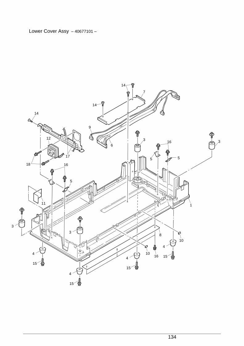
134
Lower Cover Assy – 40677101 –
14
12
9
6
18
17
16
11
3
3
4
15
4
15
410
10
1
33
7
5 5
16
8
16
15
4
15
5
14
14
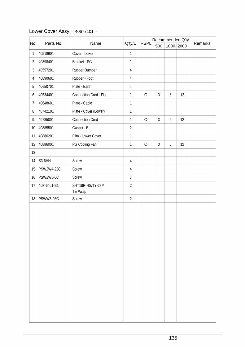
135
1 40518901 Cover - Lower 1
2 40898401 Bracket - PG 1
3 40557201 Rubber Dumper 4
4 40890601 Rubber - Foot 4
5 40650701 Plate - Earth 4
6 40534401 Connection Cord - Flat 1 O 3 6 12
7 40648601 Plate - Cable 1
8 40742101 Plate - Cover (Lower) 1
9 40785001 Connection Cord 1 O 3 6 12
10 40885501 Gasket - E 2
11 40886201 Film - Lower Cover 1
12 40886001 PG Cooling Fan 1 O 3 6 12
13
14 S3-6HH Screw 4
15 PSW2W4-22C Screw 4
16 PSW2W3-6C Screw 7
17 4LP-6401-B1 SHT18R-HS/TY-23M 2
Tie Wrap
18 PSWW3-25C Screw 2
Lower Cover Assy – 40677101 –
No. Parts No. Name Q’ty/U RSPLRecommended Q’ty
Remarks500 1000 2000
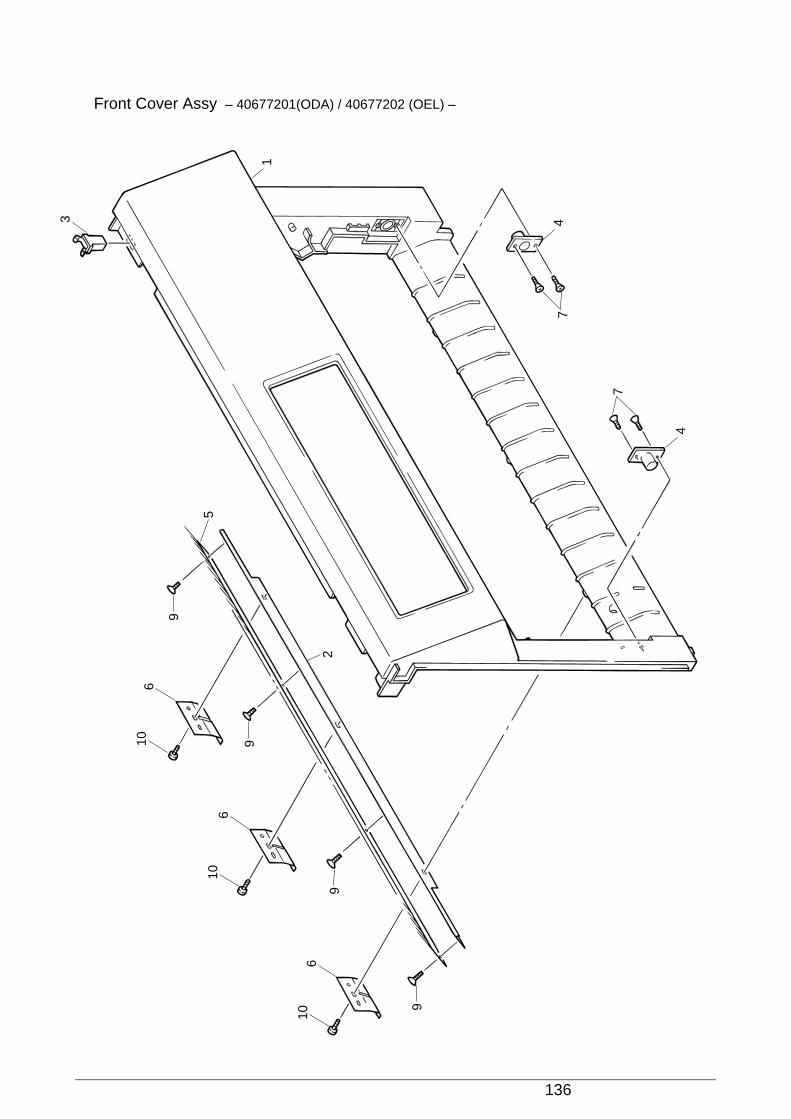
136
Front Cover Assy – 40677201(ODA) / 40677202 (OEL) –
106
9
9
9
2
4
4
1
3
7
7
5
9
10
10
6
6
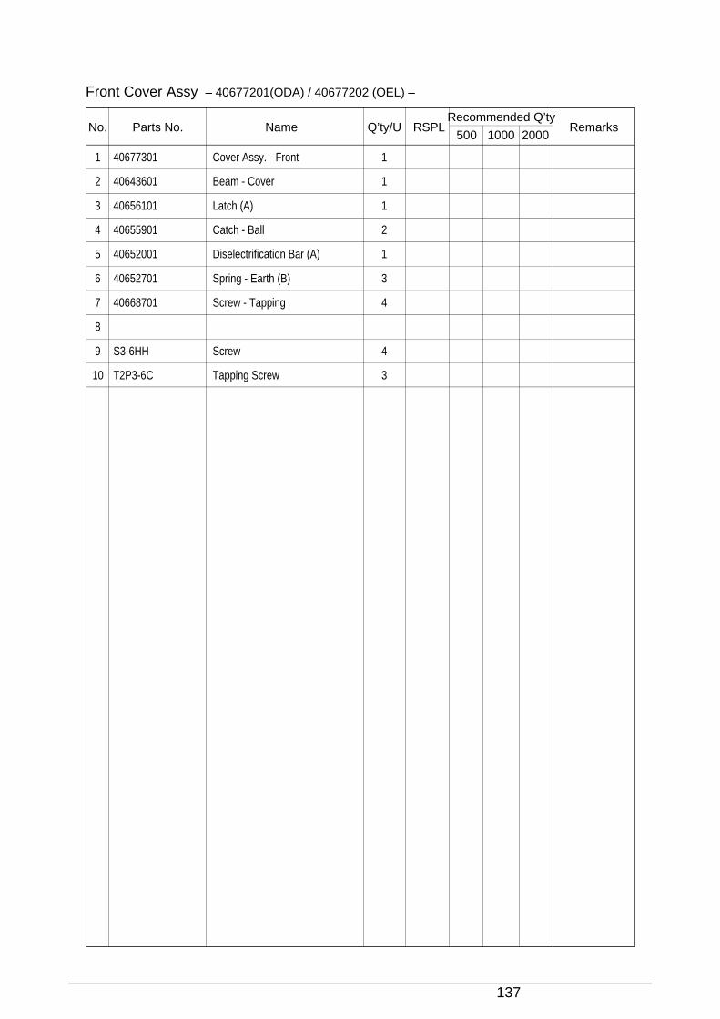
137
1 40677301 Cover Assy. - Front 1
2 40643601 Beam - Cover 1
3 40656101 Latch (A) 1
4 40655901 Catch - Ball 2
5 40652001 Diselectrification Bar (A) 1
6 40652701 Spring - Earth (B) 3
7 40668701 Screw - Tapping 4
8
9 S3-6HH Screw 4
10 T2P3-6C Tapping Screw 3
Front Cover Assy – 40677201(ODA) / 40677202 (OEL) –
No. Parts No. Name Q’ty/U RSPLRecommended Q’ty
Remarks500 1000 2000
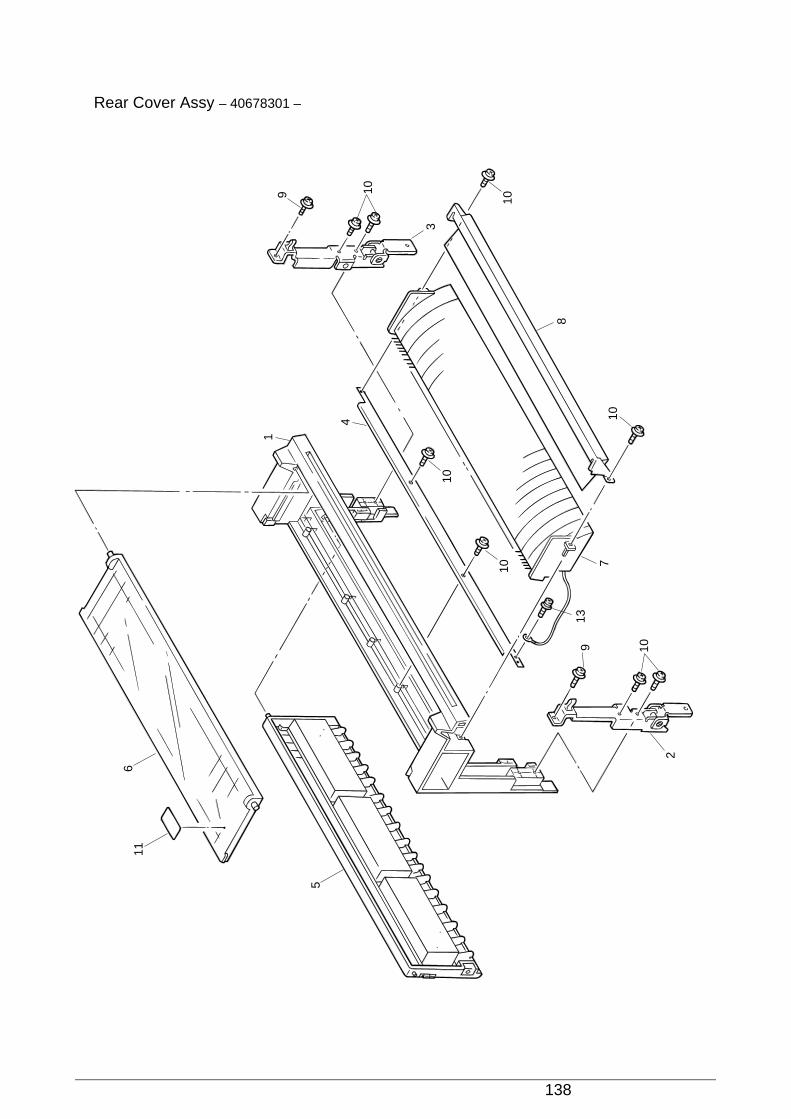
138
Rear Cover Assy – 40678301 –
116
5
9 10
10
8
10
10
109
4
1
10
3
2
7
13
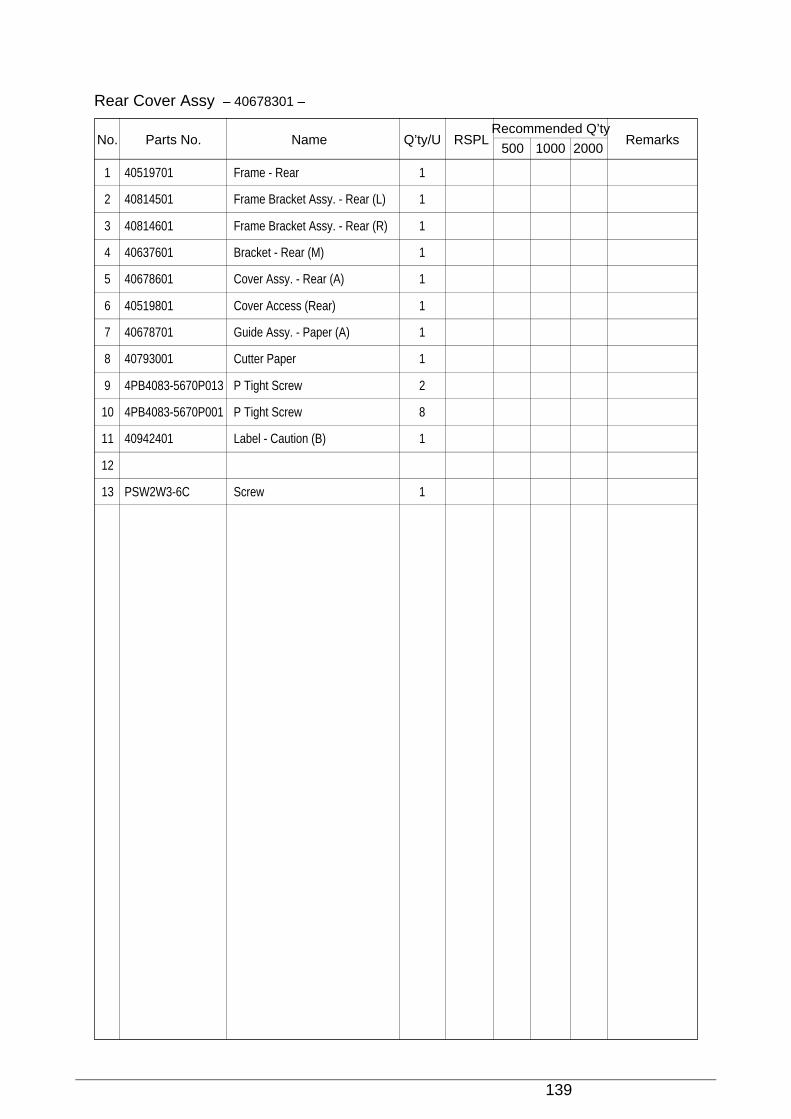
139
1 40519701 Frame - Rear 1
2 40814501 Frame Bracket Assy. - Rear (L) 1
3 40814601 Frame Bracket Assy. - Rear (R) 1
4 40637601 Bracket - Rear (M) 1
5 40678601 Cover Assy. - Rear (A) 1
6 40519801 Cover Access (Rear) 1
7 40678701 Guide Assy. - Paper (A) 1
8 40793001 Cutter Paper 1
9 4PB4083-5670P013 P Tight Screw 2
10 4PB4083-5670P001 P Tight Screw 8
11 40942401 Label - Caution (B) 1
12
13 PSW2W3-6C Screw 1
Rear Cover Assy – 40678301 –
No. Parts No. Name Q’ty/U RSPLRecommended Q’ty
Remarks500 1000 2000

40496501TH Draft Version 140
Access Cover – 40520201 –
1
6 4
3
8
10
10
10
9
78
3
46
5
2
8
13
13
13
11
12
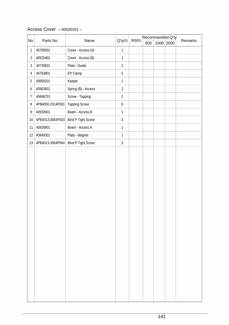
141
1 40795901 Cover - Access (A) 1
2 40520401 Cover - Access (B) 1
3 40739501 Plate - Guide 2
4 40793801 EP Clamp 2
5 40656201 Keeper 1
6 40963601 Spring (B) - Access 2
7 40668701 Screw - Tapping 2
8 4PB4050-2914P001 Tapping Screw 6
9 40930001 Beam - Access B 1
10 4PB4013-3064P003 Bind P Tight Screw 3
11 40929901 Beam - Access A 1
12 40949301 Plate - Magnet 1
13 4PB4013-3064P004 Bind P Tight Screw 3
Access Cover – 40520201 –
No. Parts No. Name Q’ty/U RSPLRecommended Q’ty
Remarks500 1000 2000

142
Frame Assy. - OpePane – 40755801 –
3
2
46
8
9
9
1
5

143
1 40678901 Frame - OpePane (Sticking) 1 O 5 10 20
2 40751001 POA-PCB 1 O 5 10 20
3 40742901 Connector Assy. 1 O 5 10 20
4 40666701 Sheet - OpePane 1
5 40519501 Frame - OpePane 1
6 40658101 Plate - Acryl 1
7
8 T2P2-6C Tapping Screw 4
9 T2P3-6C Tapping Screw 3
Frame Assy. - OpePane – 40755801 –
No. Parts No. Name Q’ty/U RSPLRecommended Q’ty
Remarks500 1000 2000
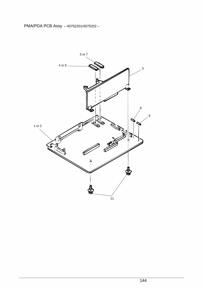
144
PMA/PDA PCB Assy – 40752201/4075202 –
4 or 6
5 or 7
1 or 2
3
8
9
11

145
1 40750401 PMA-PCB 1 O 5 10 20 (ODA)
2 40750402 PMA-PCB 1 O 5 10 20 (OEL)
3 40750701 PDA-PCB 1 O 5 10 20
4 40751201 Control ROM Writing Specifications 1 O 5 10 20 (ODA)
5 40751301 Font ROM Writing Specifications 1 O 5 10 20 (ODA)
6 40756201 Control ROM Writing Specification 1 O 5 10 20 (OEL)
7 40784201 Font ROM Writing Specifications 1 O 5 10 20 (OEL)
8 540A2036M1632 Fuse(237-06.3) 1 O 10 20 40
9 540A2036M1502 Fuse(GGS5) 1 O 10 20 40
10
11 PSWW3-6C Screw 2
PMA/PDA PCB Assy – 40752201/4075202 –
No. Parts No. Name Q’ty/U RSPLRecommended Q’ty
Remarks500 1000 2000
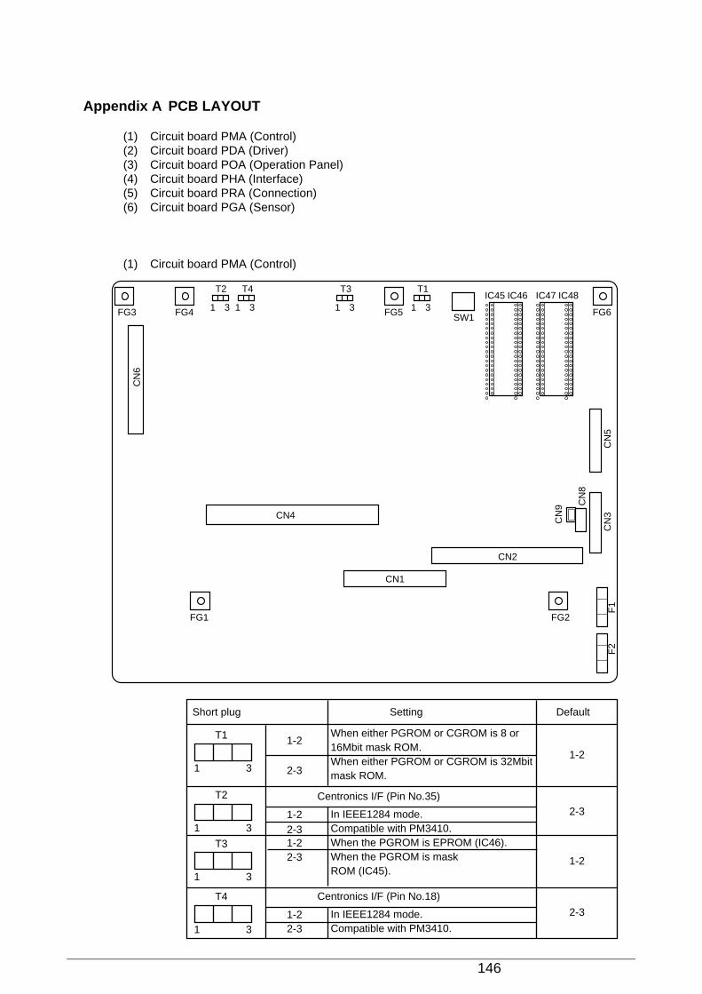
146
Appendix A PCB LAYOUT
(1) Circuit board PMA (Control)(2) Circuit board PDA (Driver)(3) Circuit board POA (Operation Panel)(4) Circuit board PHA (Interface)(5) Circuit board PRA (Connection)(6) Circuit board PGA (Sensor)
(1) Circuit board PMA (Control)
FG3 FG4
FG1 FG2
FG5
T2 T4 T3 T1
FG6SW1
IC45 IC46 IC47 IC48
CN
5F
1F
2C
N3
CN
8
CN
6
CN
9
CN4
CN1
CN2
1 3 1 3 1 3 1 3
Short plug Setting Default
T1
1 3
T2
1 3
T3
1 3
T4
1 3
1-21-2
2-3
1-2
2-3
2-3
1-2
1-22-3
2-3
1-22-3
Centronics I/F (Pin No.35)
When either PGROM or CGROM is 8 or 16Mbit mask ROM.When either PGROM or CGROM is 32Mbit mask ROM.
In IEEE1284 mode.Compatible with PM3410.When the PGROM is EPROM (IC46).When the PGROM is mask ROM (IC45).
Centronics I/F (Pin No.18)
In IEEE1284 mode.Compatible with PM3410.

147
(3) Circuit board POA (Operation Panel)
CN
1
ON-LINE
POWER
ALARM
ON-LINE
LED1
LED2
LED3GROUP
SW1SW2 ITEM
SW3OPTION
SW4
MENUSW8
CONFIGSW7
SHIFTSW13
PATHSW6
FF/LOADSW10
LFSW11
TEARSW12
PARKSW9
STORESW5
CN2
IC1
(4) Circuit board PHA (Interface)
CN
2
CN15
FG4 FG3 FG2FG6
FG5 FG1CN11
CN9 CN3CN5
CN7CN6
CN12CN4
CN1
CN13
CN14
(2) Circuit board PDA (Driver)
CN1
CN5
FG1 FG2
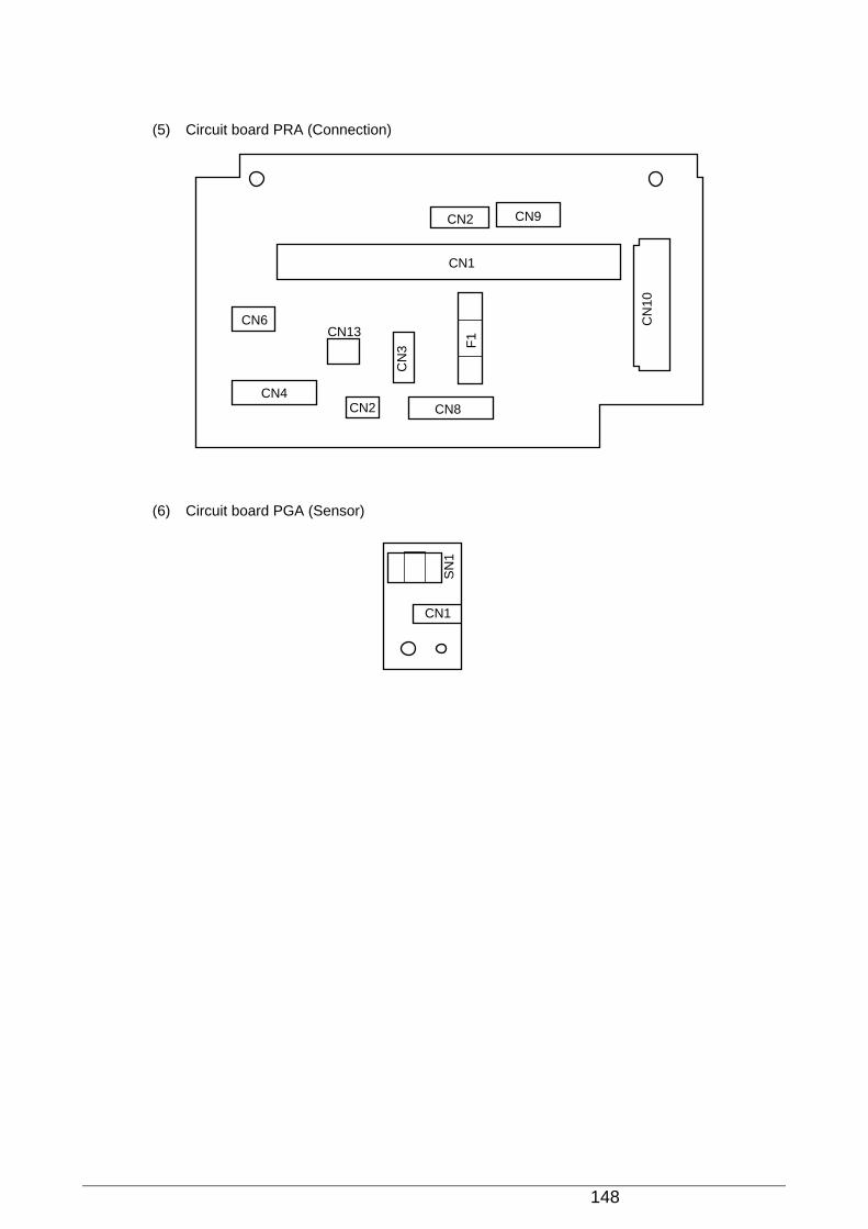
148
(5) Circuit board PRA (Connection)
CN1
CN2 CN9
CN6
CN4CN2
CN13
CN8
CN
10
CN
3 F1
(6) Circuit board PGA (Sensor)
SN
1
CN1

152
2.2.1 Operation at power on
After power is turned on, an RST OUT signal is sent from the printer control board to reset theprinter. When the reset is canceled, the 80C51 CPU performs initialization. Initialization consistsof setting the 80C51 timer, and setting the serial mode.
2.2.2. RS-232C interface
The DTR, SSD, TD and RTS signals output by the 80C51 are converted to RS-232C signals byline driver SN75188 (Q1) and sent to the interface.
In addition, signals DSR, CTS, CD, and RD on the RS232C interface are converted to TTL levelby line receiver SN75189 (Q2) and input to the 80C51.
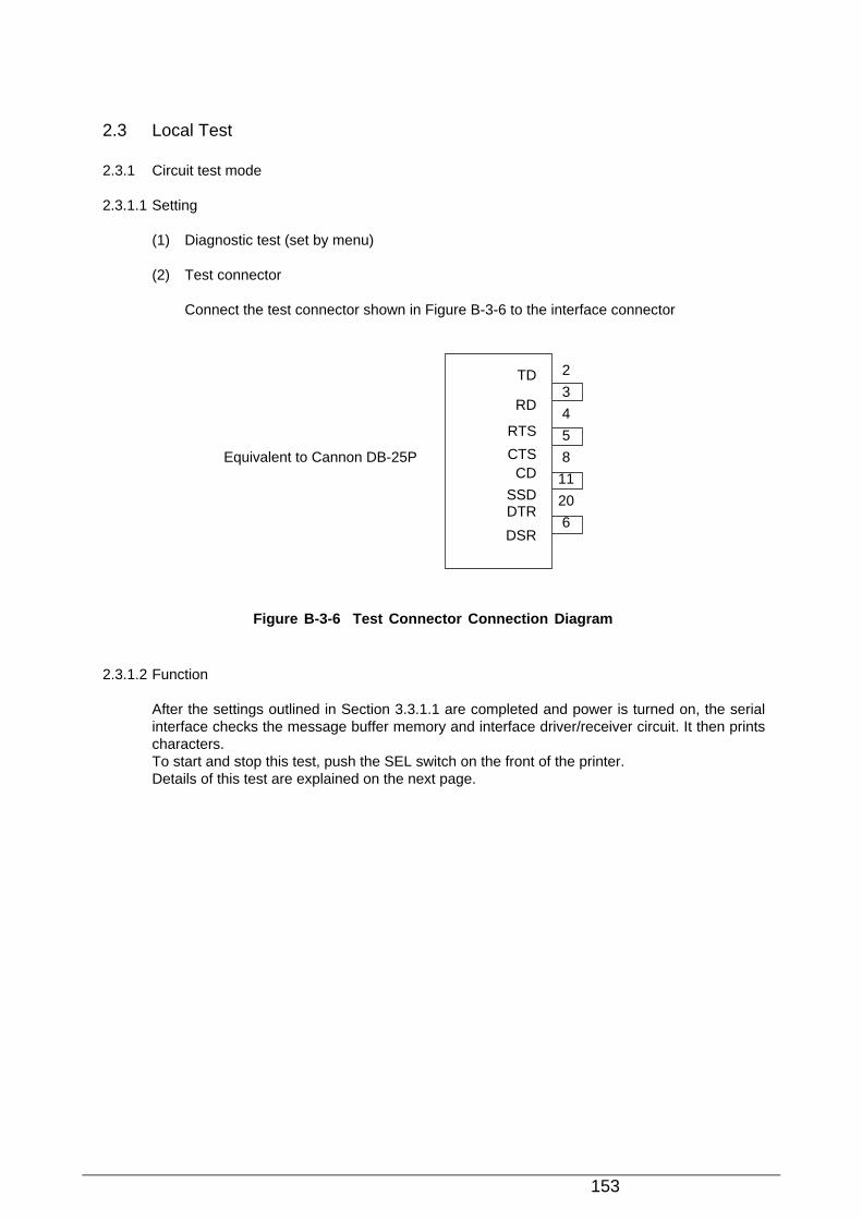
153
2.3 Local Test
2.3.1 Circuit test mode
2.3.1.1 Setting
(1) Diagnostic test (set by menu)
(2) Test connector
Connect the test connector shown in Figure B-3-6 to the interface connector
Figure B-3-6 Test Connector Connection Diagram
2.3.1.2 Function
After the settings outlined in Section 3.3.1.1 are completed and power is turned on, the serialinterface checks the message buffer memory and interface driver/receiver circuit. It then printscharacters.To start and stop this test, push the SEL switch on the front of the printer.Details of this test are explained on the next page.
Equivalent to Cannon DB-25P
TD
RD
RTS
CTSCD
SSDDTR
DSR
2
3
4
5
8
11
20
6

154
(1) The program revision using two numerical characters is printed.
(2) “LOOP TEST” is printed.
(3) Memory is checked for the message buffer.
(4) Prints “OK” is printed if the memory check is OK and “BAD” is printed if the memory checkfails.
(5) Output level to DTR, RTS, and SSD signals is dropped low. If DSR, CTS, or CD signals isHigh, “IF BAD” is printed. If DSR, CTS, and CD signals are all Low, “IF OK” is printed.
(6) Output level to DTR, RTS, and SSD signals is raised high. If DSR, CTS, or CD signals is Low,“IF BAD” is printed. If DSR, CTS, and CD signals are all High, “IF OK” is printed.
(7) Transmits characters codes from 20H to 7FH is transmitted by SD signal. At the same time,characters are received by the RD signal and stored in the message buffer.
(8) The characters that were stored in the message buffer as indicated in (7) are printed.
(9) Steps (1) through (8) are repeated until test is interrrupted.
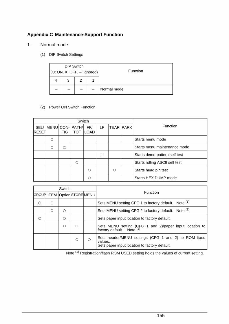
155
Appendix.C Maintenance-Support Function
1. Normal mode
(1) DIP Switch Settings
(2) Power ON Switch Function
Function
SwitchFunctionMENUSEL/
RESETPATH/TOF
CON-FIG
LFFF/LOAD
PARKTEAR
Starts menu mode
Starts menu maintenance mode
Starts demo-pattern self test
Starts rolling ASCII self test
Starts head pin test
Starts HEX DUMP mode
Switch
ITEMGROUP STOREOption MENU
Sets MENU setting CFG 1 to factory default. Note (1)
Sets MENU setting CFG 2 to factory default. Note (1)
Sets paper input location to factory default.
Sets MENU setting (CFG 1 and 2)/paper input location to factory default. Note (1)
Sets header/MENU settings (CFG 1 and 2) to ROM fixed values. Sets paper input location to factory default.
Note (1) Registration/flash ROM USED setting holds the values of current setting.
DIP Switch
(O: ON, X: OFF, –: ignored) Function
34 12
Normal mode– – – –
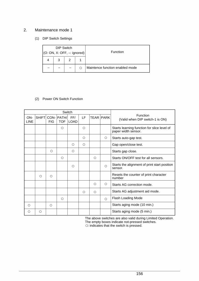
156
2. Maintenance mode 1
(1) DIP Switch Settings
(2) Power ON Switch Function
DIP Switch
(O: ON, X: OFF, –: ignored) Function
34 12
Maintence function enabled mode– – –
SwitchFunction
(Valid when DIP switch-1 is ON)SHIFTON-LINE
PATH/TOF
CON-FIG
LFFF/LOAD
PARKTEAR
Starts learning function for slice level of paper width sensor.
Starts auto-gap test.
Gap open/close test.
Starts gap close.
Starts ON/OFF test for all sensors.
Starts the alignment of print start position sensor.
Resets the counter of print character number
Starts AG correction mode.
Starts AG adjustment aid mode.
Flash Loading Mode
Starts aging mode (10 min.)
Starts aging mode (5 min.)
The above switches are also valid during Limited Operation.The empty boxes indicate not-pressed switches. : indicates that the switch is pressed.
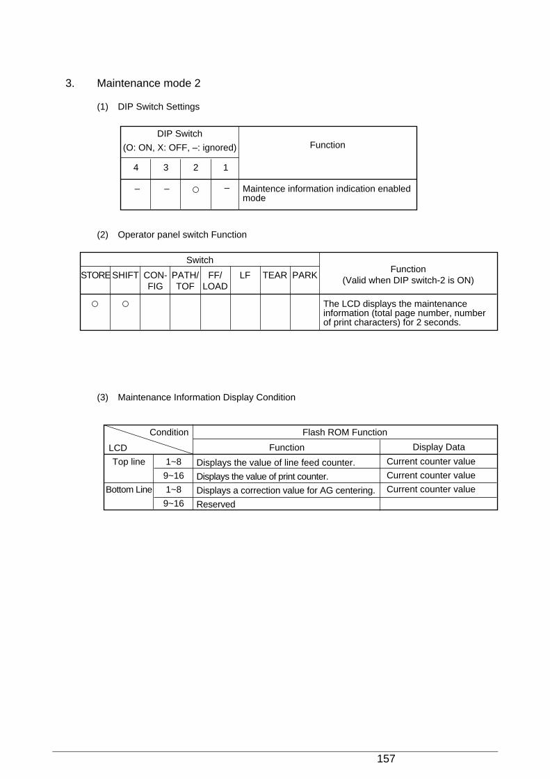
157
3. Maintenance mode 2
(1) DIP Switch Settings
(2) Operator panel switch Function
DIP Switch
(O: ON, X: OFF, –: ignored) Function
34 12
Maintence information indication enabled mode
– – –
SwitchFunction
(Valid when DIP switch-2 is ON)SHIFTSTORE PATH/TOF
CON-FIG
LFFF/LOAD
PARKTEAR
The LCD displays the maintenance information (total page number, number of print characters) for 2 seconds.
(3) Maintenance Information Display Condition
Flash ROM FunctionCondition
LCD
Top line
Bottom Line
1~8
9~16
1~8
9~16
Current counter value
Current counter value
Current counter value
Function Display Data
Displays the value of line feed counter.
Displays the value of print counter.
Displays a correction value for AG centering.
Reserved

158
(4) Stored historical page number data
This function counts a page each 11inch and stores it to EEPROM.The storage capacity for the counter is 3byte, which equals to pages for 70 years at 20000pages/ month.As the printer has no function which is capable of resetting this counter, line feed frequencycan be known since the printer's shipment.
(5)a)Stored histrical printed character number data
This function counts the number of actually printed characters and stores it to EEPROM.It reads and analyses the characters from receiving buffer and identifies the characters whichhas been actually printed and counts them.The count of image data for any DPI should be increases by one character each 12 columns,The storage capacity for the counter is 3byte, which equals to 430 million characters with 256characters counted as 1 count.As the printer has the function which is capable of resetting this counter to zero, The usagefrequency of print head ribbon can be known as an index by resetting this counter whenreplacing a print head and ribbon set.
b)Printed character number counter resetting function
Activating Power on, holding SHIFT + CONFIG switches.ReleasingCondition When DIP switch 1 has been turned on.Subject Printed character number counter (EEPROM data)
This function resets the counter for the number of printed characters to zero, which is storedin the EEPROM.This function is advanced in the following steps.1) This function starts, showing the following indications on the LCD.
Top line : INITIALIZINGBottom Line : COUNTER RESET
2) It resets the printed character number counter to "0" and rewrite the EEPROM.3) The printer returns to the normal Power On condition.