thales alenia space cryptographic module for microsemi
TRANSCRIPT
Thales Alenia Space
Cryptographic Module for
Microsemi RTAX FPGA non-
proprietary Security Policy
Thales Alenia Space
Prepared by jtsec Beyond IT Security SL
Version: 1.6

Version: 1.13 Date: 27/09/2021
Thales Alenia Space Cryptographic Module for Microsemi RTAX FPGA non-proprietary Security Policy Thales Alenia Space
PAGE 2/33
Index
1 Revision history .................................................................................................................................... 6
2 Introduction .......................................................................................................................................... 9
2.1 Overview ..................................................................................................................................... 9
2.2 Document organization ............................................................................................................ 10
3 Module specification .......................................................................................................................... 11
3.1 Module description and cryptographic boundary .................................................................... 11
3.2 Cryptographic module ports and interfaces ............................................................................. 12
3.3 Modes of operation and security functions .............................................................................. 14
3.4 Critical Security Parameters ...................................................................................................... 14
4 Roles, authentication and services ..................................................................................................... 16
4.1 Roles and authentication .......................................................................................................... 16
4.2 Services ..................................................................................................................................... 16
4.2.1 Encryption service ................................................................................................................ 18
4.2.2 Decryption Service ................................................................................................................ 19
5 Physical security ................................................................................................................................. 22
6 Operational environment ................................................................................................................... 23
6.1 Tested configuration ................................................................................................................. 23
7 Cryptographic key management ........................................................................................................ 24
7.1 Random Number Generation.................................................................................................... 24
7.2 Key generation .......................................................................................................................... 24
7.3 Key entry and output ................................................................................................................ 24
7.4 Key storage ............................................................................................................................... 25
7.5 Key zeroization .......................................................................................................................... 25
8 EMI/EMC ............................................................................................................................................ 26
9 Self-Test .............................................................................................................................................. 27
9.1 Power-up self-test ..................................................................................................................... 27
10 Mitigation of other attacks ............................................................................................................ 28
Version: 1.13 Date: 27/09/2021
Thales Alenia Space Cryptographic Module for Microsemi RTAX FPGA non-proprietary Security Policy Thales Alenia Space
PAGE 3/33
11 Design assurance ........................................................................................................................... 29
11.1 Configuration management ...................................................................................................... 29
11.2 Configuration items identification method .............................................................................. 29
12 Crypto officer and user guidance .................................................................................................. 30
12.1 Operation rules ......................................................................................................................... 30
12.2 Secure distribution .................................................................................................................... 30
12.3 Integrity and confidentiality assurance..................................................................................... 31
12.4 Installation and initialization instructions ................................................................................. 31
12.5 Secure operation ....................................................................................................................... 31
13 Glossary and abbreviations ........................................................................................................... 32
14 Reference document ..................................................................................................................... 33

Version: 1.13 Date: 27/09/2021
Thales Alenia Space Cryptographic Module for Microsemi RTAX FPGA non-proprietary Security Policy Thales Alenia Space
PAGE 4/33
Index of tables
TABLE 1: REVISION HISTORY ................................................................................................................................ 8
TABLE 2: SECURITY REQUIREMENTS ..................................................................................................................... 10
TABLE 3: TASE-CM-PACE PORTS AND INTERFACES .............................................................................................. 14
TABLE 4: MODES OF OPERATION AND SECURITY FUNCTIONS..................................................................................... 14
TABLE 5: LIST OF CSPS USED BY THE MODULE ....................................................................................................... 15
TABLE 6: USERS ROLE AND AUTHORIZED SERVICES .................................................................................................. 16
TABLE 7: DESCRIPTION OF AUTHORIZED SERVICES .................................................................................................. 18
TABLE 8: TESTED CONFIGURATION ...................................................................................................................... 23
TABLE 9: KEYS STORAGE IN EEPROM MEMORY .................................................................................................... 25
TABLE 10: POWER-UP SELF-TEST DESCRIPTION ...................................................................................................... 27

Version: 1.13 Date: 27/09/2021
Thales Alenia Space Cryptographic Module for Microsemi RTAX FPGA non-proprietary Security Policy Thales Alenia Space
PAGE 5/33
Index of figures
FIGURE 1: COMMUNICATION PROCESS BETWEEN THE GPC AND PACE TRANSPONDER ................................................... 9
FIGURE 2: THE PHYSICAL AND LOGICAL BOUNDARY OF TASE-CM-PACE .................................................................. 12
FIGURE 3: ENCRYPTION PROCESS ........................................................................................................................ 18
FIGURE 4: FRAME FORMAT OF CIPHERTEXT DATA INPUT .......................................................................................... 19
FIGURE 5: DECRYPTION PROCESS ........................................................................................................................ 21
FIGURE 6: TOP VIEW OF THE TASE-CM-PACE ..................................................................................................... 22
FIGURE 7: BOTTOM VIEW OF THE TAS-CM-PACE ................................................................................................ 22
FIGURE 8: KEY UPLOADING ENVIRONMENT ........................................................................................................... 24

Version: 1.13 Date: 27/09/2021
Thales Alenia Space Cryptographic Module for Microsemi RTAX FPGA non-proprietary Security Policy Thales Alenia Space
PAGE 6/33
1 REVISION HISTORY
Revision Date Remark
1.0 05/16/2019 Initial Version
1.1 12/06/2019 Modified the sections 5.1, 6.4 and 8
Updated the documentation package version in section 14
1.2 05/09/2019 Updated the documentation package version in section 14
1.3 30/01/2020 Added the sections 3.4 and revision history
Modified the sections 3.3, 5 and 12.1
Updated the documentation package version in section 14
1.4 07/02/2020 Modified the sections 3.2, 4.2.2, 9 and 11.2
1.5 14/02/2020 Updated the documentation package version in section 14
1.6 26/05/2020 Updated the section 3.1
Updated the section 4.1 to specify that bypass capability is not supported.
Updated section 5 to specify the silicone varnish employed to protect the module
Updated the section 12.4
Updated the documentation package version in section 14
Version: 1.13 Date: 27/09/2021
Thales Alenia Space Cryptographic Module for Microsemi RTAX FPGA non-proprietary Security Policy Thales Alenia Space
PAGE 7/33
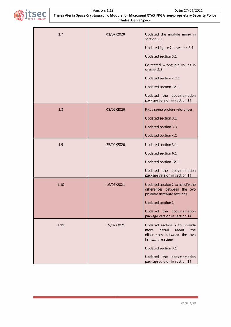
1.7 01/07/2020 Updated the module name in section 2.1
Updated figure 2 in section 3.1
Updated section 3.1
Corrected wrong pin values in section 3.2
Updated section 4.2.1
Updated section 12.1
Updated the documentation package version in section 14
1.8 08/09/2020 Fixed some broken references
Updated section 3.1
Updated section 3.3
Updated section 4.2
1.9 25/09/2020 Updated section 3.1
Updated section 6.1
Updated section 12.1
Updated the documentation package version in section 14
1.10 16/07/2021 Updated section 2 to specify the differences between the two possible firmware versions
Updated section 3
Updated the documentation package version in section 14
1.11 19/07/2021 Updated section 2 to provide more detail about the differences between the two firmware versions
Updated section 3.1
Updated the documentation package version in section 14
Version: 1.13 Date: 27/09/2021
Thales Alenia Space Cryptographic Module for Microsemi RTAX FPGA non-proprietary Security Policy Thales Alenia Space
PAGE 8/33
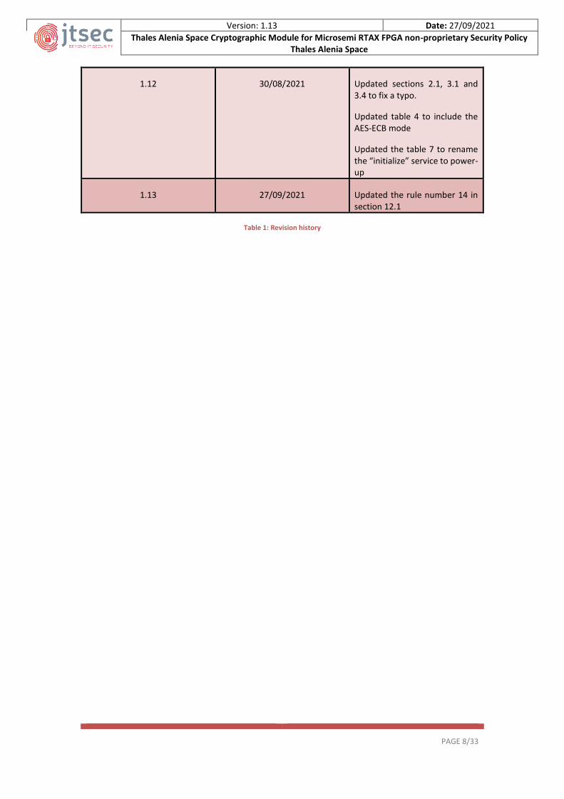
1.12 30/08/2021 Updated sections 2.1, 3.1 and 3.4 to fix a typo.
Updated table 4 to include the AES-ECB mode
Updated the table 7 to rename the “initialize” service to power-up
1.13 27/09/2021 Updated the rule number 14 in section 12.1
Table 1: Revision history
Version: 1.13 Date: 27/09/2021
Thales Alenia Space Cryptographic Module for Microsemi RTAX FPGA non-proprietary Security Policy Thales Alenia Space
PAGE 9/33
2 INTRODUCTION
2.1 OVERVIEW
This document is the non-proprietary FIPS 140-2 Security Policy for the Thales Alenia Space Cryptographic
Module for Microsemi RTAX FPGA which will also be referred to as “TASE-CM-PACE” through this
document. This Security Policy specifies the security rules under which the cryptographic module should
operate to meet FIPS 140-2 Level 1 requirements.
This cryptographic module has been developed by Thales Alenia Space and it has been implemented
within the Ground Cryptographic Processor (GCP) placed on Earth and within the Plankton Aerosol, Cloud,
ocean Ecosystem (PACE) transponder unit. The aim of this cryptographic module is to enable the NASA to
cipher the communications in the GCP and decipher and authenticate them in the transponder unit using
AES-CCM. It is able to encrypt/decrypt and authenticate messages from 24 bytes to 312 bytes of
information in 64 bits blocks.
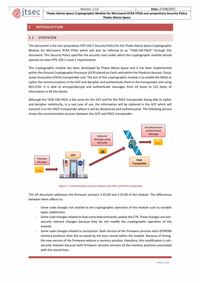
Although the TASE-CM-PACE is the same for the GCP and for the PACE transponder being able to cipher
and decipher indistinctly, in a real case of use, the information will be ciphered in the GCP which will
transmit it to the PACE transponder where it will be deciphered and authenticated. The following picture
shows the communication process between the GCP and PACE transponder:
This SP document addresses the firmware versions 3.32.00 and 3.32.04 of the module. The differences
between them affects to:
- Some code changes not related to the cryptographic operation of the module such as variable
types redefinition.
- Some code changes related to how some telecommands update the CTR. These changes are non-
security relevant changes because they do not modify the cryptographic operation of the
module.
- Some code changes related to zeroization. Both version of the firmware zeroizes extra EEPROM
memory positions than the occupied by the keys stored within the module. Because of timing,
the new version of the firmware reduces a memory position, therefore, this modification is not-
security relevant because both firmware versions zeroizes all the memory positions associated
with the stored keys.
Plaintext Message
Ciphered Message using
AES-CCM
Deciphered and authenticated
Message
GCP
PACE Transponder
Figure 1: Communication process between the GPC and PACE transponder

Version: 1.13 Date: 27/09/2021
Thales Alenia Space Cryptographic Module for Microsemi RTAX FPGA non-proprietary Security Policy Thales Alenia Space
PAGE 10/33
Moreover, the Helion IP core responsible for providing the cryptographic operation to the module is the
same for both firmware versions.
The FIPS 140-2 security levels for the module are as follow:
Security Requirements Security Level
1 Cryptographic Module Specification 1
2 Cryptographic Module Ports and Interfaces 1
3 Roles, Services, and Authentication 1
4 Finite State Model 1
5 Physical Security 1
6 Operational Environment N/A
7 Cryptographic Key Management 1
8 EMI/EMC 1
9 Self-Test 1
10 Design Assurance 1
11 Mitigation of Other Attacks N/A
Overall Level 1
Table 2: Security requirements
2.2 DOCUMENT ORGANIZATION
This security policy is one part in a FIPS 140-2 submission package. The submission package contains:
- Security Policy: This document.
- Algorithm certificates: See section “3.3 Modes of operation and security functions”.
- Functional specification and design documentation: See sections “3.1 Module description and
cryptographic boundary” and “3.2 Cryptographic module ports and interfaces” and [TASFS].
- User guide: See section “12 Crypto officer and user guidance”.
- Finite state machine model: See [TASFSM].
- Configuration item list: See [TASCIL].

Version: 1.13 Date: 27/09/2021
Thales Alenia Space Cryptographic Module for Microsemi RTAX FPGA non-proprietary Security Policy Thales Alenia Space
PAGE 11/33
3 MODULE SPECIFICATION
The TASE-CM-PACE is a hardware module based on a One Time Programmable FPGA (OTP FPGA) which
implements twice the Helion IP cores for supporting AES-CCM encryption/decryption within the
environment of the PACE mission. This cryptographic module is classified by FIPS 140-2 as multiple-chip
embedded.
In addition, the cryptographic module includes the telecommand (TC) and telemetry (TM) request
libraries necessary to control and monitor the cryptographic operations and communications between
the GCP and the PACE transponder.
3.1 MODULE DESCRIPTION AND CRYPTOGRAPHIC BOUNDARY
The FPGA is composed by:
- Two Helion IP cores for AES-CCM encryption/decryption and authentication.
- The CM Management block for the management of the keys CRCs, keys CTRs, etc., relative to the
AES-CCM keys.
- Other functional logic (green blocks) not related to the cryptographic operations, because its
function is performing tasks concerning to the communications and moreover it is not connected
to the cryptographic block as it is shown in the “Figure 2: The Physical and Logical Boundary of
TASE-CM-PACE”.
The “Figure 2: The Physical and Logical Boundary of TASE-CM-PACE” depicts the block diagram specifying
the physical and logical boundary for the TASE-CM-PACE, showing all the input/output interfaces and the
information flow described below:
- The ciphertext can be entered into the TASE-CM-PACE through two data input interfaces (one is
the ISBT Asics output CDI-1 and the other one is the auxiliary input for testing CDI-2) and once it
is inside the FPGA, it goes to the Helion IP core to be deciphered before being output from the
TASE-CM-PACE in plaintext form through the data output interface (PDO).
- The plaintext is entered through another data input interface (PDI) into the TASE-CM-PACE and
it is ciphered by the Helion IP core before being output from the module through the data output
interface (CDO).
- All the AES-CCM keys are entered into the TASE-CM-PACE through the data input interface
KEYUART by the crypto officer and once the CM Management Block calculates their CRCs and
verifies that they match with the received CRCs through the same interface, both the keys and
their CRCs are stored into the EEPROM memory.
- All the TM requests and TCs are entered into the TASE-CM-PACE through the control input
interfaces HKUART, KEYUART and GND-UART.
- All the status output information related to the state of the cryptographic module is output from
the TASE-CM-PACE through the HKUART interface. The status output information related to the
verification of each key CRC is output through the KEYUART interface and the status output
information related to the length and rate of the input plaintext is output through the GND-UART
interface.

Version: 1.13 Date: 27/09/2021
Thales Alenia Space Cryptographic Module for Microsemi RTAX FPGA non-proprietary Security Policy Thales Alenia Space
PAGE 12/33
- The green block called “other logic” which corresponds to the downlink of the module is related
to the signal modulation. The information (green arrow) between this block and the UART I/F is
because the HKUART interfaces allow configuring this block by using two TCs not related to the
cryptographic operation of the module.
- The green block called “ISBT ASIC” is considered out of the cryptographic boundary because
although it is responsible for providing the ciphered input to the module as a result of the
demodulation of the received signal, a malfunctioning of this block during the demodulation
process cannot cause a release of CSPs, plaintext or sensitive information. If an error occurs
during the demodulation process and the CD-1 signal does not have the format specified in the
section “4.2.1 Encryption service”, then the CD-1 signal will not be processed by the TASE-CM-
PACE.
- The information flow into the module is represented by the dark blue arrows.
Figure 2: The Physical and Logical Boundary of TASE-CM-PACE
3.2 CRYPTOGRAPHIC MODULE PORTS AND INTERFACES
The following table summarizes the mapping between the logical interfaces required by FIPS 140-2 and
the physical ports of the TASE-CM-PACE:
FIPS 140-2 logical interface
Cryptographic module physical port
Description and purpose
Data input PDI GND_UART_RX (pin 136) These interfaces are used to enter the plaintext to be ciphered into the TASE-CM-PACE

Version: 1.13 Date: 27/09/2021
Thales Alenia Space Cryptographic Module for Microsemi RTAX FPGA non-proprietary Security Policy Thales Alenia Space
PAGE 13/33
CDI-1
ASIC_TC_DATA (pin 140) These interfaces are used to enter the ciphertext to be deciphered into the TASE-CM-PACE
ASIC_TC_CLOCK (pin 141)
ASIC_TC_VALID (pin 142)
ASIC_BIT_LOCK (pin 143)
KEY_UART_RX (pin 158)
All the AES-CCM keys to be used by the module in encrypt/decrypt operations are entered into the TASE-CM-PACE through this interface
CDI-2 AUXILIARY_ENA (pin 124)
These interfaces are used to enter the ciphertext to be deciphered into the TASE-CM-PACE in case of use the auxiliary input AUXILIARY_CMD (pin 125)
Data output
CDO
GND_TC_DATA (pin 133) These interfaces are used to output the ciphertext from the TASE-CM-PACE
GND_TC_CLOCK (pin 134)
GND_TC_VALID (pin 135)
PDO
DECRYPT_VALID (pin 197) These interfaces are used to output the plaintext from the TASE-CM-PACE
DECRYPT_DATA (pin 198)
DECRYPT_CLOCK (pin 199)
Control Input
HK_UART_RX_A (pin 146) This interface is used to input TC to the TASE-CM-PACE
HK_UART_RX_B (pin 147)
This interface is used to input TC to the TASE-CM-PACE as the HK_UART_RX_A in order to provide redundancy
KEY_UART_RX (pin 158)
Besides of being used to enter the keys into the module, this interface is used to control what key is going to be entered into the module for each TC as detailed in the TASFS
GND_UART_RX (pin 136)
Besides of being used to enter the plaintext to be ciphered into the TASE-CM-PACE, this interface is used to enter the TCs and TMs related to the plaintext input configuration as the Nonce and rate configuration or obtain the length of the entered plaintext
KEY_CABLE_3 (pin 153) If the harness is plugged (All these pins = 0) before turning on the TASE-CM-PACE, the keys entry will start once the cryptographic module is turned on
KEY_CABLE_2 (pin 154)
KEY_CABLE_1 (pin 155)
Status output
KEY_UART_TX (pin 159)
The purpose of this interface is to output the TM related to the keys CRC checking during the key entry process
GND_UART_TX (pin 137)
This interface returns the TMs through this interface to answer the TMs Request related to the plaintext input to be encrypted as the plaintext length or communication rate
Version: 1.13 Date: 27/09/2021
Thales Alenia Space Cryptographic Module for Microsemi RTAX FPGA non-proprietary Security Policy Thales Alenia Space
PAGE 14/33
HK_UART_TX_A (pin 148) The aim of this interface is to output the rest of TM
HK_UART_TX_B (pin 149) This interface has the same aim as the HK_UART_TX_A in order to provide redundancy
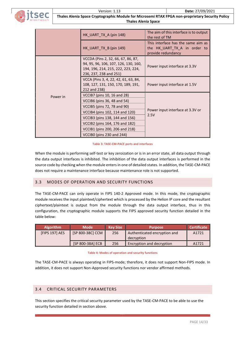
Power in
VCCDA (Pins 2, 32, 66, 67, 86, 87, 94, 95, 96, 106, 107, 126, 130, 160, 194, 196, 214, 215, 222, 223, 224, 236, 237, 238 and 251)
Power input interface at 3.3V
VCCA (Pins 3, 4, 22, 42, 61, 63, 84, 108, 127, 131, 150, 170, 189, 191, 212 and 238)
Power input interface at 1.5V
VCCIB7 (pins 10, 16 and 28)
Power input interface at 3.3V or 2.5V
VCCIB6 (pins 36, 48 and 54)
VCCIB5 (pins 72, 78 and 90)
VCCIB4 (pins 102, 114 and 120)
VCCIB3 (pins 138, 144 and 156)
VCCIB2 (pins 164, 176 and 182)
VCCIB1 (pins 200, 206 and 218)
VCCIB0 (pins 230 and 244)
Table 3: TASE-CM-PACE ports and interfaces
When the module is performing self-test or key zeroization or is in an error state, all data output through
the data output interfaces is inhibited. The inhibition of the data output interfaces is performed in the
source code by checking when the module enters in one of detailed states. In addition, the TASE-CM-PACE
does not require a maintenance interface because maintenance role is not supported.
3.3 MODES OF OPERATION AND SECURITY FUNCTIONS
The TASE-CM-PACE can only operate in FIPS 140-2 Approved mode. In this mode, the cryptographic
module receives the input plaintext/ciphertext which is processed by the Helion IP core and the resultant
ciphertext/plaintext is output from the module through the data output interface, thus in this
configuration, the cryptographic module supports the FIPS approved security function detailed in the
table below:
Algorithm Mode Key Size Purpose Certificate
[FIPS 197] AES [SP 800-38C] CCM 256 Authenticated encryption and decryption
A1721
[SP 800-38A] ECB 256 Encryption and decryption A1721
Table 4: Modes of operation and security functions
The TASE-CM-PACE is always operating in FIPS-mode; therefore, it does not support Non-FIPS mode. In
addition, it does not support Non-Approved security functions nor vendor affirmed methods.
3.4 CRITICAL SECURITY PARAMETERS
This section specifies the critical security parameter used by the TASE-CM-PACE to be able to use the
security function detailed in section above.
Version: 1.13 Date: 27/09/2021
Thales Alenia Space Cryptographic Module for Microsemi RTAX FPGA non-proprietary Security Policy Thales Alenia Space
PAGE 15/33
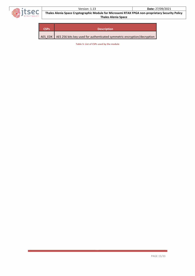
CSPs Description
AES_EDK AES 256 bits key used for authenticated symmetric encryption/decryption
Table 5: List of CSPs used by the module

Version: 1.13 Date: 27/09/2021
Thales Alenia Space Cryptographic Module for Microsemi RTAX FPGA non-proprietary Security Policy Thales Alenia Space
PAGE 16/33
4 ROLES, AUTHENTICATION AND SERVICES
4.1 ROLES AND AUTHENTICATION
As the FIPS 140-2 standard requires, the TASE-CM-PACE supports the User and Crypto Officer roles. It’s
important to keep in mind that the cryptographic module does not allow concurrent operators to operate
at the same time, because it is programed to operate in sequential execution. In addition, the module
does not implement authentication mechanisms because Security Level 1 does not require it.
The table below summarizes the allowed services for each role implemented by the TASE-CM-PACE. It’s
important to consider that the role will be assumed implicitly depending on the accessed service by the
operator:
Role Authorized services
User
All the services related to the cryptographic operations as perform self-test on demand, encrypt/decrypt operations and get the state of the TASE-CM-PACE
Crypto Officer
The crypto officer is the ones in charge of installing the TASE-CM-PACE in a secure manner and performing the AES keys entry and zeroization
Table 6: Users role and authorized services
The TASE-CM-PACE does not support maintenance role because it does not need logical or physical
maintenance services. In addition, it does not support bypass capability.
4.2 SERVICES
Once module installation has been performed successfully, each role (user and crypto officer) can use the
services and keys/CSPs detailed in the table below depending on its type of access (R for reading access,
W for writing access and X for execution access) by using the specified API TC/TM Request and actions.
The access types to CSPs are denoted as follows:
- ‘R’: Reading access
- ‘W’: Writing access
- ‘X’: Execution access
Authorized Services
Roles Description Keys and
CSPs API TC/TM Request or action Access
Power-up User Used to power-up the TASE-CM-PACE
N/A
When the module is powered on, it operates automatically in FIPS 140-2 Approved mode of operation
N/A
Self-test User Used to perform the power-up self-test
N/A
The self-test is executed automatically when TASE-CM-PACE is powered-on, therefore it can be executed on demand by resetting or rebooting the cryptographic module
N/A

Version: 1.13 Date: 27/09/2021
Thales Alenia Space Cryptographic Module for Microsemi RTAX FPGA non-proprietary Security Policy Thales Alenia Space
PAGE 17/33
Enter AES keys CO
Used to enter the AES keys into the TASE-CM-PACE
AES_ EDK
To enter the keys into the cryptographic module, the crypto officer must follow these steps: - Step 1: The crypto officer must
plug the harness for key uploading to the KEYUART interface.
- Step 2: The crypto officer must wait until the power-up self-tests and key zeroizations are completed successfully
- Step 3: Once the TASE-CM-PACE is in Key-Uploading state, the crypto officer can enter up to 32 keys into the cryptographic module verifying that the upload is success by using this command for each of them:
- TC Key loading - TM Request Key loading status
Note: Consult the [TASFS] for detailed information
W
Encrypt User
Used to encrypt an entry plaintext with the desired AES key
AES_ EDK Follow the detailed process in section “4.2.1 Encryption service”
X
Decrypt User
Used to decrypt an entry ciphertext with the desired AES key
AES_ EDK Follow the detailed process in section “4.2.2 Decryption Service” for detailed information
X
Zeroize CO
Used to zeroize the EEPROM memory pages where the AES keys are stored
AES_EDK
The zeroization is performed automatically before the user proceed with the new keys loading as it is indicated in section “7.5 Key zeroization”
W
Get status User
Used to obtain the current status of the TASE-CM-PACE
N/A
The status of the module can be obtained through the HKUART interface as a response to the following TM Request: - TM Request Show Crypto-
status
N/A
Set key User
Used to choose one of the 32 keys stored in the EEPROM memory to carry out and encryption or
AES_EDK
Prior to perform an encryption or decryption operation, the user can use the Set New Key TC detailed in the [TASFS] document to choose a new key
X
Version: 1.13 Date: 27/09/2021
Thales Alenia Space Cryptographic Module for Microsemi RTAX FPGA non-proprietary Security Policy Thales Alenia Space
PAGE 18/33
decryption operation
Table 7: Description of authorized services
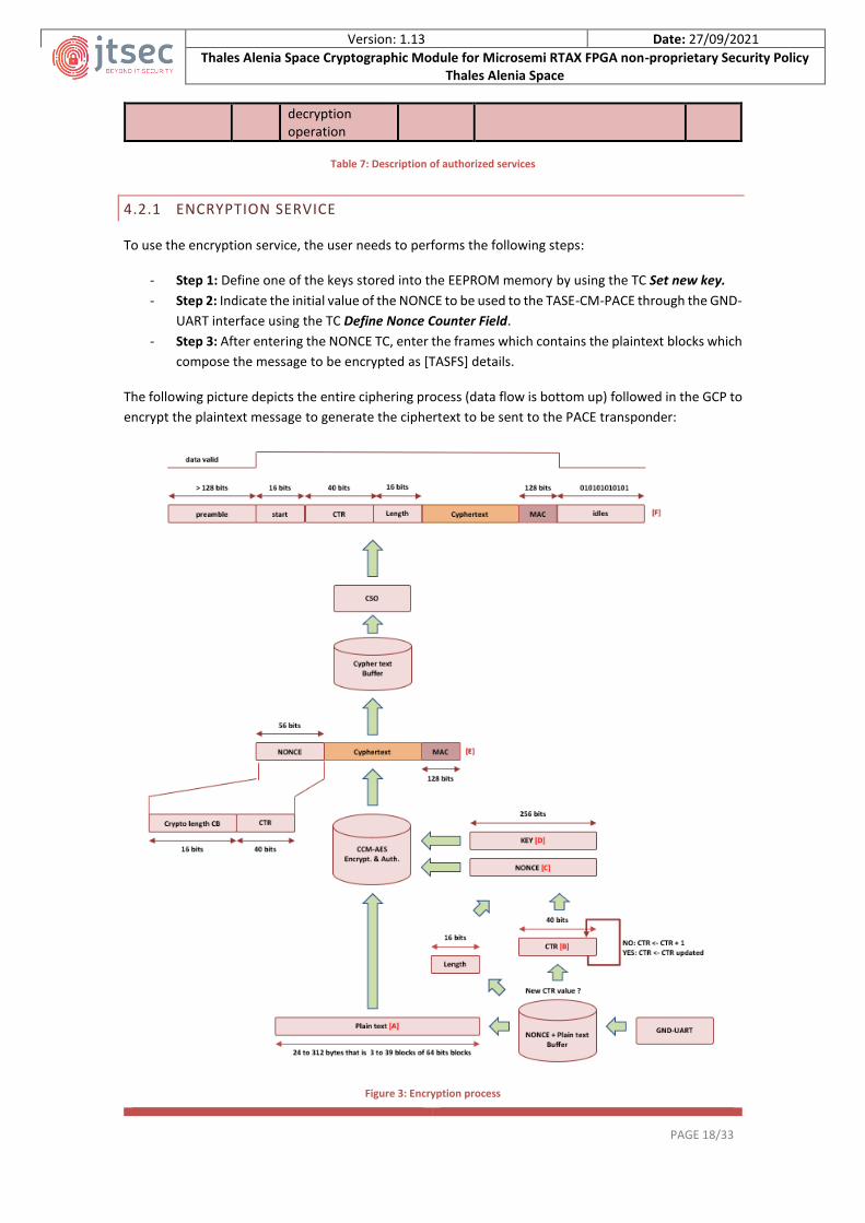
4.2.1 ENCRYPTION SERVICE
To use the encryption service, the user needs to performs the following steps:
- Step 1: Define one of the keys stored into the EEPROM memory by using the TC Set new key.
- Step 2: Indicate the initial value of the NONCE to be used to the TASE-CM-PACE through the GND-
UART interface using the TC Define Nonce Counter Field.
- Step 3: After entering the NONCE TC, enter the frames which contains the plaintext blocks which
compose the message to be encrypted as [TASFS] details.
The following picture depicts the entire ciphering process (data flow is bottom up) followed in the GCP to
encrypt the plaintext message to generate the ciphertext to be sent to the PACE transponder:
Figure 3: Encryption process

Version: 1.13 Date: 27/09/2021
Thales Alenia Space Cryptographic Module for Microsemi RTAX FPGA non-proprietary Security Policy Thales Alenia Space
PAGE 19/33
1. Once the initial value of the Nonce counter field (CTR) [B] is set, the FPGA will send each plaintext
input data frame [A] to the Helion IP core in conjunction with the Nonce counter field (CTR),
whose value will be incremented by 1 for each new plaintext frame.
2. The Helion IP core receive the Nonce input [C] that is the message length concatenate with the
Nonce counter field (CTR).
3. At the same time the TASE-CM-PACE indicates to the Helion IP core the key ID [D] to be loaded
from EEPROM memory. This key id is previously defined through the HK interface as indicated in
section “Load new key” of the TASFS document.
4. Once the Helion IP core has all the needed information to proceed with the encryption operation,
the cryptographic buffer receives the frame [E] composed by the Nonce (56 bits), the ciphertext
and the Message Authentication Code (MAC).
5. Finally, the TASE-CM-PACE generates the final frame [F] with the correct format to be deciphered
in the PACE transponder. This frame is composed by the preamble sequence (>128 bits), followed
by the START sequence (16bits), followed by the Nonce (CTR + length = 40 and 16 bits
respectively), followed by the ciphertext, followed by the MAC (128 bits) and the idle sequence
(01010101) which is endlessly repeated without constraints in its length.
Note: The following rules will apply to the interfaces operation:
- The GND-UART, HK-UART and KEY-UART baud rate is 115200bps.
- The GND-UART, HK-UART and KEY-UART configuration is odd parity, 1 start bit logic 0 and 1 stop
bit logic one.
- The inter-bytes gap is below 5 symbols for the GND-UART, HK-UART and KEY-UART.
- The GND-UART ignores any incomplete incoming TC or TM request.
- The plain text input data blocks of 64 bits in length are concatenated two by two by the Helion
AES-CCM IP core to process them as a 128 bits data packets.
- The Nonce counter field (CTR) is incremented by 1 for each new plaintext frame regardless of the
key used for the cryptographic operation. This ensures not to repeat the combination of Nonce
and internal counter in any case.
4.2.2 DECRYPTION SERVICE
The decryption service is carried out in the TASE-CM-PACE located in the PACE transponder. It will start
when the TASE-CM-PACE receives through the ciphertext input interface a frame which begins with the
preamble sequence (>128 bits only in transmission initialization). The following 16 bits compose the start
sequence followed by the Nonce counter field (CTR (40 bits) and the length (16 bits) of the ciphered
message. Finally, the frame contains the ciphertext followed by the MAC (128 bits) and the idle sequence
(01010101) which is endlessly repeated without constraints in its length:
Figure 4: Frame format of ciphertext data input
Then, to use the decryption service, the user must follow these steps:

Version: 1.13 Date: 27/09/2021
Thales Alenia Space Cryptographic Module for Microsemi RTAX FPGA non-proprietary Security Policy Thales Alenia Space
PAGE 20/33
- Step 1: Define one of the keys stored into the EEPROM memory by using the TC Set new key.
- Step 2: Wait for receiving a frame with the format specified above.
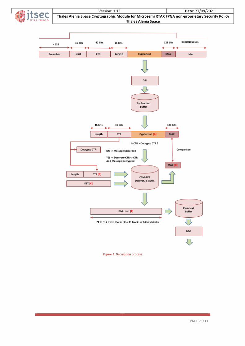
The following picture depicts the decryption process followed in the PACE transponder to decipher the
information received from the GCP:
1. The TASE-CM-PACE extract the ciphertext [A], after splitting the input data frame.
2. The Helion IP core receives the Nonce Counter (CTR) [B] concatenate with the length.
3. The Helion IP core receives the key ID [C], previously defined through the HK interface as
indicated in section “Load new key” of the TASFS document.
4. The Helion IP core calcs the MAC [D] with all the received parameters and then TASE-CM-PACE
compares it with the MAC which composes the received frame. If they match, the ciphertext is
deciphered and authenticated, obtaining the ciphertext [E] that is sent to the plaintext buffer.
Note: The following rules will apply to the GND-UART interface operation:
The TASE-CM-PACE does not output any unauthenticated data packet.
Version: 1.13 Date: 27/09/2021
Thales Alenia Space Cryptographic Module for Microsemi RTAX FPGA non-proprietary Security Policy Thales Alenia Space
PAGE 21/33
Figure 5: Decryption process
Version: 1.13 Date: 27/09/2021
Thales Alenia Space Cryptographic Module for Microsemi RTAX FPGA non-proprietary Security Policy Thales Alenia Space
PAGE 22/33
5 PHYSICAL SECURITY
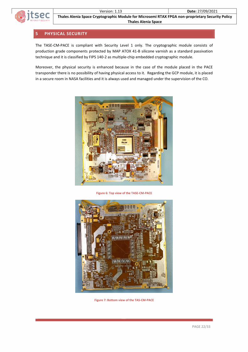
The TASE-CM-PACE is compliant with Security Level 1 only. The cryptographic module consists of
production grade components protected by MAP ATOX 41-B silicone varnish as a standard passivation
technique and it is classified by FIPS 140-2 as multiple-chip embedded cryptographic module.
Moreover, the physical security is enhanced because in the case of the module placed in the PACE
transponder there is no possibility of having physical access to it. Regarding the GCP module, it is placed
in a secure room in NASA facilities and it is always used and managed under the supervision of the CO.
Figure 6: Top view of the TASE-CM-PACE
Figure 7: Bottom view of the TAS-CM-PACE

Version: 1.13 Date: 27/09/2021
Thales Alenia Space Cryptographic Module for Microsemi RTAX FPGA non-proprietary Security Policy Thales Alenia Space
PAGE 23/33
6 OPERATIONAL ENVIRONMENT
The TASE-CM-PACE is a multiple-chip embedded cryptographic module which encompasses a FPGA and
an EEPROM memory used to store the AES-CCM keys and their CRCs. Therefore, the operational
environment corresponds with the firmware contained in the OTP FPGA which is classified as non-
modifiable operational environment because once the OTP FPGA is burned/programmed, it is not possible
to modify the firmware contained in it, and therefore, the requirements of this section are not applicable.
6.1 TESTED CONFIGURATION
The TASE-CM-PACE is composed by a FPGA which provides all the necessary to operate and interconnect
the Helion IP cores (AES-CCM IP cores) to perform cryptographic operations and the EEPROM memory to
store all the AES-CCM keys and their CRCs.
The model of each component is specified in the table below:
Device Model
FPGA RTAX2000S
IP cores Helion AES-CCM IP core
EEPROM 28C010T
Table 8: Tested configuration

Version: 1.13 Date: 27/09/2021
Thales Alenia Space Cryptographic Module for Microsemi RTAX FPGA non-proprietary Security Policy Thales Alenia Space
PAGE 24/33
7 CRYPTOGRAPHIC KEY MANAGEMENT
7.1 RANDOM NUMBER GENERATION
The TASE-CM-PACE does not support random number generation.
7.2 KEY GENERATION
The TASE-CM-PACE does not implement key generation algorithms.
7.3 KEY ENTRY AND OUTPUT
All the keys used by the TASE-CM-PACE to perform encryption or decryption operations must be entered
into the cryptographic module. The module is able to store up to 32 AES-CCM keys and their CRCs
identifying them using a unique ID from 1 to 32.
To carry out the key entry in a secure way, the crypto officer is the ones in charge of performing the
following steps to comply with FIPS 140-2 standard:
1. Firstly, the keys must be manually entered (via USB) into the computer (non-networked) used to
load the keys into the module.
2. Secondly, the crypto officer must plug the harness to the KEYUART interface prior to powering
on the TASE-CM-PACE.
3. Once the harness is connected, the crypto officer must power on the cryptographic module.
4. After the cryptographic module is powered-up and the self-tests are completed successfully, the
cryptographic module will detect that the harness is plugged and starts with the keys zeroization.
5. When the zeroization is completed, the key uploading process starts and the crypto officer can
upload up to 32 keys in total by using the scheme depicted in the image below and the following
sequence of TC and TM request:
o TC: Key loading → This TC is used to load new key into the TASE-CM-PACE
o Enter the new key generated externally in plaintext form via software using a PC.
o TM Request: Key loading status → This TM Request is used to check the CRC of the last
uploaded key
Figure 8: Key uploading environment
The upper limit is 32 keys; however, the crypto officer can enter a lower number of keys into the TASE-
CM-PACE.

Version: 1.13 Date: 27/09/2021
Thales Alenia Space Cryptographic Module for Microsemi RTAX FPGA non-proprietary Security Policy Thales Alenia Space
PAGE 25/33
Regarding the key output, the cryptographic module does not support CSP’s and private keys output,
because it does not allow access to the keys from outside of the cryptographic boundary.
7.4 KEY STORAGE
Once the crypto officer has completed the process depicted above, the keys are stored into the EEPROM
memory. Because the inhospitable conditions of space, the module has several methods to ensure the
correctness of the keys to be stored. On the one hand, each key is stored with its own CRC which will be
used before a decryption/encryption process to ensure the key is valid. On the other hand, the key storage
is performed by using the Triple Modular Redundancy (TMR) methodology in order to protect the
information against the Single Event Effects (SEE) which can disturb the keys and their CRCs content.
Therefore, the result is that each ID, key and CRC will be stored three times in one EEPROM memory page.
ID CRC Key Redundancy 1 Redundancy 2
1 CRC1 Key 1 1 CRC1 Key 1 1 CRC1 Key 1
2 CRC2 Key 2 2 CRC2 Key 2 2 CRC2 Key 2
3 CRC3 Key 3 3 CRC3 Key 3 3 CRC3 Key 3
· · · · · · · · ·
· · · · · · · · ·
· · · · · · · · ·
32 CRC32 Key 32 32 CRC32 Key 32 32 CRC32 Key 32
0 0 0 0 0 0 0 0 0
0 0 0 0 0 0 0 0 0
· · · · · · · · ·
· · · · · · · · ·
Table 9: Keys storage in EEPROM memory
When a Key stored in the EEPROM is selected, the TASE-CM-PACE applies a majority voting system for
each of its bytes using the three possible stored values. The CRC over this key is calculated and it is
compared with the CRC stored in the EEPROM, applying again the majority voting system.
7.5 KEY ZEROIZATION
The key zeroization will be performed automatically prior the key uploading process as it is specified in
section “7.3 Key entry and output”. During this process the TASE-CM-PACE will only erase the 32 memory
pages where the AES-CCM keys and CRCs are stored because these are the only memory pages which
contains keys and CSPs.
During the key zeroization process all data output interfaces are inhibited in order to prevent inadvertent
disclosure of sensitive information as the plaintext cryptographic keys or CSPS.
Version: 1.13 Date: 27/09/2021
Thales Alenia Space Cryptographic Module for Microsemi RTAX FPGA non-proprietary Security Policy Thales Alenia Space
PAGE 26/33
8 EMI/EMC
The TASE-CM-PACE complies with the EMI/EMC requirements specified by 47 Code of Federal
Regulations, Part 15, Subpart B, Unintentional Radiators, Digital Devices, Class A.
Version: 1.13 Date: 27/09/2021
Thales Alenia Space Cryptographic Module for Microsemi RTAX FPGA non-proprietary Security Policy Thales Alenia Space
PAGE 27/33
9 SELF-TEST
The module will be in Operative state once the power-up self-tests are passed successfully (status code
of the module is set to 101) and a key from the EEPROM memory is defined correctly (its CRC is verified)
to be used. Until this moment, the outputs are inhibited to avoid the inadvertent disclosure of the key
components or CSPs, thus the module is not able to output any type of cryptographic data nor perform
cryptographic operations.
Moreover, if the power-up self-test fails, the module will reach the error state, not allowing to perform
any cryptographic operation and keeping all the outputs inhibited.
9.1 POWER-UP SELF-TEST
Because the TASE-CM-PACE is a hardware cryptographic module based on an OTP FPGA whose firmware
cannot be modified as it is specified in section “6 Operational environment”, it is not necessary to
implement the integrity test of the firmware to verify its signature, so that, during the power-up self-test
the TASE-CM-PACE only performs the KAT (Known Answer Test) to verify the correct operation of the AES-
CCM, performing the ciphering/deciphering and authentication of a known piece of information.
In addition, the user can perform a power-up self-test on demand by rebooting/resetting the TASE-CM-
PACE. The KAT is applied for the Approved algorithm detailed in the table below:
Algorithm Description
AES CCM Known answer test. By performing an encryption/decryption and authentication
Table 10: Power-up self-test description
The module does not implement any critical functions that need to be tested in the power-up self-test.

Version: 1.13 Date: 27/09/2021
Thales Alenia Space Cryptographic Module for Microsemi RTAX FPGA non-proprietary Security Policy Thales Alenia Space
PAGE 28/33
10 MITIGATION OF OTHER ATTACKS
The module is not designed to mitigate other attacks which are outside of the scope of FIPS 140-2.

Version: 1.13 Date: 27/09/2021
Thales Alenia Space Cryptographic Module for Microsemi RTAX FPGA non-proprietary Security Policy Thales Alenia Space
PAGE 29/33
11 DESIGN ASSURANCE
11.1 CONFIGURATION MANAGEMENT
The configuration management list is composed by the Configuration Items version control, change
control, flaw remediation tracking and the source code revision which are managed by Thales Alenia Space
in a private Git repository with write access restricted to the authorized developers.
11.2 CONFIGURATION ITEMS IDENTIFICATION METHOD
The internal versioning of the VHDL source code is performed by Git automatically and the assigned
version and revision are used internally to control the code development, so that it must not be confused
with the final released version of the VHDL that is appended manually to the name of the VHDL code file
using the following format “PACE_WFIRST_Model.XX_YY_ZZ”, where XX is the version number, YY is the
revision number, ZZ is associated with bug fixing. In addition, the TASE-CM-PACE will be able to return the
version by using the “FW version” TM Request.
Regarding each associated module documentation, they are manually versioned by appending the version
and revision on their filename as follow: Document-X.Y. The assigned version number is stated as part of
the file name with the following naming convention:
- Naming: Name-X.Y, where Name is the unique name of the related document, and X.Y are the
version and revision of the document. Every new document is named with version v1.0.
- Version Update: When the document is modified and this modification implies major changes,
the X number must be changed. However, if changes and modifications imply minor changes,
then the Y number must be changed.
The configuration item list can be consulted in [TASCIL].
Version: 1.13 Date: 27/09/2021
Thales Alenia Space Cryptographic Module for Microsemi RTAX FPGA non-proprietary Security Policy Thales Alenia Space
PAGE 30/33
12 CRYPTO OFFICER AND USER GUIDANCE
12.1 OPERATION RULES
When the module is powered on, it is initialized to operate in FIPS mode that is its only mode of operation
complying with the following rules:
1. The cryptographic module is initialized in FIPS mode of operation automatically after the selft-
test are completed successfully.
2. The replacement or modification of the module by unauthorized users is prohibited.
3. Power-up self-test do not require any operator action to be executed.
4. Data output interfaces are inhibited during the key entry, power-up self-test, zeroization and
error states.
5. Any input interface will ignore any incomplete incoming TC or TM request.
6. Status information does not contain CSPs or sensitive data
7. The zeroization affects to the 32 EEPROM memory pages which contains the possible 32 keys to
be stored.
8. The cryptographic module does not support the maintenance interfaces or role.
9. The cryptographic module does not implement authentication mechanisms because it is not
required for Security Level 1.
10. The cryptographic module does not support manual key entry.
11. The cryptographic module does not need to implement conditional self-test.
12. The keys are entered into the TASE-CM-PACE in plaintext form via software.
13. The cryptographic module does not output CSPs, secret or private keys from the module.
14. The maximum number of invocations for each key is 240-1 that is lower than the maximum limit
of 261 times stated in the SP 800-38C.
15. In case of module reset; the Crypto Officer is the responsible of setting the Nonce counter field
(CTR) value to the next of the last invoked in order to avoid the possibility of using a Nonce
counter field (CTR) previously used. The Nonce counter field (CTR) can be read by using the TM
Request subtype 112 (Request CTR value) of the HKUART interface detailed in the [TASFS]
document. And then Ciphering Nonce counter field could be set by using the TC subtype 96 of
the GNDUART interface.
16. During the power-up self-test, the module does not perform integrity test because the firmware
contained in the OTP FPGA cannot be modified after programming the FPGA.
17. All the keys are stored into an EEPROM memory with a unique identifier which allow the user
operate with them without having access to their content or value.
18. The crypto officer is the ones in charge to carry out the keys zeroization and the uploading of the
new keys to be stored into the EEPROM memory.
19. If the TASE-CM-PACE is in Error state, it will not be able to perform cryptographic operations.
12.2 SECURE DISTRIBUTION
The module is shipped only to NASA via certified courier service by Thales Alenia Space, and the it is
shipped in Thales boxes with Thales adhesive; therefore, the recipient will be able to notice if it is
tampered. In addition, due to the module is an OTP FPGA, it is not possible to modify its firmware,
notwithstanding, once the module is installed, it is possible to verify that the firmware version is correct
as it is detailed in section 12.4 Installation and initialization instructions.

Version: 1.13 Date: 27/09/2021
Thales Alenia Space Cryptographic Module for Microsemi RTAX FPGA non-proprietary Security Policy Thales Alenia Space
PAGE 31/33
12.3 INTEGRITY AND CONFIDENTIALITY ASSURANCE
As it is mentioned in the section “9.1 Power-up self-test” it is not necessary to perform the firmware
verification because the TASE-CM-PACE is based on an OTP FPGA whose firmware cannot be modified
once the FPGA is programmed. Therefore, the integrity and confidentiality of the cryptographic module
are assured by following the secure distribution methodology specified in the section above and by
verifying the firmware version after following the steps to initialize the module in a secure manner as is
specified in the section below.
12.4 INSTALLATION AND INITIALIZATION INSTRUCTIONS
When NASA receives the module, the crypto officer will be the one in charge of interconnecting and
anchoring the support in the GCP and the PACE transponder, then the module can be initiated in a secure
manner by following the steps below:
Step 1: Once the TASE-CM-PACE is installed and interconnected in a secure manner, it does not contain
any AES-CCM key to operate, therefore, the first step is to proceed with the key entry into the
cryptographic module. The crypto officer that is responsible for the CSPs and keeping them into the
module must follow the steps described in section “7.3 Key entry and output” to insert up to 32 keys into
the module and to store them into the EEPROM memory.
Step 2: After the keys are entered and stored into the cryptographic module, the crypto officer must
power off the TASE-CM-PACE and unplug the harness from the KEYUART port.
Step 3: Finally, it is possible to verify the correct version of the firmware installed in the module by using
the “FW version” TM Request detailed in the [TASFS] after powering on the module.
12.5 SECURE OPERATION
When the module has been configured and the AES-CCM keys stored in a secure manner by the crypto
officer, the TASE-CM-PACE can be powered on to be used by or user role by using the TCs and TMs request
detailed in [TASFS] and the procedures specified in “Table 6: Users role and authorized services”.
Once the self-tests are passed successfully, the data encryption and decryption can be performed without
additional security measures, because the module is always operating in FIPS mode. In addition, the
module does not return any private secret, key component or CSP through the output data interface.

Version: 1.13 Date: 27/09/2021
Thales Alenia Space Cryptographic Module for Microsemi RTAX FPGA non-proprietary Security Policy Thales Alenia Space
PAGE 32/33
13 GLOSSARY AND ABBREVIATIONS
AES Advanced Encryption Standard CCM Counter with CBC-MAC EEPROM Electrically Erasable Programmable Read-Only Memory EMI/EMC Electromagnetic Interference/Electromagnetic Compatibility FGPA Field Programmable Gate Array GCP Ground Centre Processor IP Intellectual Property MAC Message Authentication Code OTP FPGA One Time Programmable FPGA PACE Plankton, Aerosol, Cloud, ocean Ecosystem TASE-CM-PACE Thales Alenia Space Cryptographic Module TC Telecommand TM Telemetry UART Universal Asynchronous Receiver-Transmitter

Version: 1.13 Date: 27/09/2021
Thales Alenia Space Cryptographic Module for Microsemi RTAX FPGA non-proprietary Security Policy Thales Alenia Space
PAGE 33/33
14 REFERENCE DOCUMENT
TASSP Thales Alenia Space FIPS 140-2 Security Policy-1.13 TASCIL Thales Alenia Space FIPS 140-2 Configuration Item List-1.123 TASFSM Thales Alenia Space FIPS 140-2 Finite State Model-1.13 TASFS Thales Alenia Space FIPS 140-2 Functional Specification-1.13 RT-PROTO-FPGAS Prototyping for Space-Flight Designs with Microsemi (“MSC”) RT-PROTO FPGAS
FIPS 197 Advanced Encryption Standard (AES)
SP 800-38A Recommendation for Block Cipher Modes of Operation
SP 800-38C Recommendation for Block Cipher Modes of Operation: The CCM Mode for Authentication and Confidentiality