tgr6000 - resources.aimtti.comresources.aimtti.com/manuals/tgr6000_instruction_manual-iss9.pdf ·...
TRANSCRIPT

TGR6000Fast Sweep 6GHz RF Signal Generator INSTRUCTION MANUAL

1
Table of Contents Introduction 2 Specification 3 Safety 6 Installation 7 Connections 7
Front Panel Connections 7 Rear Panel Connections 7
Manual Operation 9 General 9 Frequency and Level Setting 11 Step Sweep 11 List Sweep 12 Common Sweep Functions and Attributes 13 Trim 14 Factory Default Settings 15
Utilities 17 Store 17 Recall 17 Edit List Name 17 Set Edit Mode 17 Ref Socket 18 Interfaces 18 Buzzer 18 Power Up Mode 18 Version Info 18 Calibration 18
Remote Interface Operation 19 Address Selection, RS232 Baud Rate and LAN status 19 Remote/Local Operation 19 RS232 Interface 20 USB Interface 21 LAN Interface 21 GPIB Interface 23 Status Reporting 24 Power-on and Remote Operation Default Settings 27
Remote Commands 28 Remote Command Format 28 GPIB Remote Command Format 28 Command List 29
Maintenance 33 Full operating instructions for this instrument can also be found in the appropriate product folder of the accompanying CD-ROM or downloaded from: http://www.aimtti.com/support.

2
Introduction This fast sweep programmable RF generator provides a synthesised low noise output over the frequency range 10MHz to 6000MHz and output level range -110dBm to +7dBm.
The output amplitude and/or frequency can be swept over the full range of each in a single sweep. The instrument can be set up to perform two types of sweep. The first sweep type is a Step Sweep in which the start and stop conditions are defined, together with the number of points in the sweep, linear or logarithmic spacing between points, and a dwell time at each point. The other sweep type is a List Sweep in which up to 1000 points are defined in a sweep list, with the frequency, level and dwell time specified for each point. Both types of sweep can be free run or triggered by a Sweep Trigger from a variety of sources; in addition, a Point Trigger can also be defined for each individual step of the sweep. A rear panel SYNC output signal indicates when the output is stable, and can be user-programmed to be high or low. The output level can be adjusted to correct for external equipment frequency response using the TRIM function. The TRIM function consists of a user programmable list of up to 100 amplitude adjustment /frequency pairs. When turned on, the TRIM function adjusts the output level by an amount linearly interpolated between the frequencies specified in the list. The resultant output level is required to remain within the normal output level limits specified for the instrument; automatic testing is applied to ensure this and a warning is issued if the desired output violates this requirement. The instrument provides non-volatile storage for up to 12 instrument setups and up to 16 sweep lists. The instrument is remotely controllable via LAN, USB, RS232 or GPIB, all of which are simultaneously available.

3
Specification
FREQUENCY Frequency Range: 10MHz – 6000MHz Setting Resolution: 10Hz Accuracy and Stability: see Reference Frequency Phase Noise: 500MHz Carrier :
<-110dBc/Hz (typ) @ 20kHz offset <-120dBc/Hz (typ) @ 100kHz offset 3GHz Carrier: <-95dBc/Hz (typ) @20kHz offset <-110dBc/Hz (typ) @100kHz offset 6GHz Carrier: <-89dBc/Hz (typ) @ 20kHz offset <-104dBc/Hz (typ) @100kHz offset
Residual FM: 12 Hz @ 500MHz – Equivalent peak deviation in a 300Hz to 3.4kHz bandwidth.
Switching Speed: <8ms to settle within 100Hz or 0.1ppm of final frequency, if greater.
REFERENCE FREQUENCY Internal Reference Accuracy: <± 1ppm, 15ºC – 30ºC
<± 2ppm, 5ºC – 40ºC Internal Reference Stability: <1ppm/year 10MHz Reference In/Out: Rear panel BNC; can be disabled when not required for input or
output. External Reference IN: 10MHz, 50Ω input impedance, 2 – 5Vpp
Automatic detection and selection when external reference signal is present and Reference IN is selected from front panel. Front panel indicator shows when External Reference is active.
Internal Reference OUT: 10MHz, 50Ω output impedance, >2Vpp into 50Ω Signal present when Reference OUT is selected from front panel.
OUTPUT LEVEL Output Level range: –110dBm to +7dBm VSWR > -18.0dBm < 1.7:1 (typ)
<= -18.0dBm < 1.5:1 (typ) Settling Time: <8ms to settle to within 0.2dB Setting Resolution: 0.1dB, 0.01uV –1mV Accuracy: ± 2dBm Harmonically Related Signals: <-25dBc @ +7dBm, <-30dBc@levels <=0dBm 30 – 6000MHz
<-25dBc@levels <=0dBm 10 – 30MHz Sub-harmonically Related Signals:
≤3000MHz : None >3000MHz :<–40dBc (typ) @ +7dBm.

4
Non-harmonic Spurii: <–50dBc >10kHz offset 10–3000MHz * <-44dBc >10kHz offset 3000MHz–6000MHz ** *<-45dBc >10kHz offset 1900–2150MHz **<-39dBc >10kHz offset 3800–4300MHz
Output Impedance: 50Ω Output Connector: Type N Reverse Voltage Protection: 50V DC Output Switch: RF OUT On/Off switch with indication of ON status
FREQUENCY and AMPLITUDE SWEEP Step Sweep
Step frequency and/or amplitude according to a formula over a specified number of points. Maximum 1000 points.
Formula specifies: Frequency start/stop Amplitude start/stop Dwell time at each step – programmable 0.01s to 10.000s
Sweep - continuous or single. Linear or logarithmic step spacing. Sweep up or down. Sweep triggering - manual, external trigger, timed (0.1 – 999.9sec), or via remote interface. Step triggering (Point Trigger mode) - manual, external trigger, or via remote interface. Sync signal (‘output stable’) available during dwell time. Programmable to be high or low.
List Sweep As for Step Sweep except that a user defined list of frequency, amplitude and dwell time values defines each sweep point. The list can be created within the instrument or downloaded via the remote interfaces. Current sweep list plus up to 16 stored lists, each a maximum of 1000 points, stored in non-volatile memory.
TRIG IN Input DC coupled External Trigger Input signal used to trigger start of sweep and/or step changes when Point Trigger mode is enabled. Input Threshold: 1.65V nominal. Trigger polarity can be set to Negative Edge or
Positive Edge. Input Protection: Maximum/minimum external applied voltage is +6V or –1V.
SYNC Output Rear panel output SYNC signal goes to its active state when generator output frequency & level have settled within specification after a step change during sweep. SYNC returns to inactive state at end of specified dwell period. Active Output Level: +5V (Active state set to ‘Pos’) or 0V (Active state set to ‘Neg’) Output Impedance: 50Ω. Minimum load impedance is also 50Ω. Output Protection: Output will withstand accidental short circuit to ground and applied
external voltages up to +5V.

5
User Level Compensation Table (TRIM) A table of frequency/gain pairs allows the user to modify the generator output level with respect to frequency to calibrate an entire test set up or improve the calibration of the generator alone. The table can be created within the instrument or downloaded via the remote interfaces. Maximum 100 points.
INTERFACES Full digital remote control facilities are available through the RS232, USB, LAN and GPIB interfaces.
RS232: Standard 9-pin D-connector. Variable Baud rate can be set between 1200 and 115200 Baud maximum
GPIB: Conforming with IEEE488.1 and IEEE488.2 USB: Standard USB 2.0 hardware connection. Operates as a virtual COM port. LAN: Ethernet 100/10base-T hardware connection.
GENERAL Power: 110-240VAC ±10% 50/60Hz; 100-120VAC ±10% 400Hz; 60VA max.
Installation Category II. Display 20 character x 4 row backlit alphanumeric LCD Data Entry: Value entry of all major parameters direct by numeric keys, or by rotary
control and up/down keys at selected resolution. Value stepping of frequency and level in user-defined increments is also possible using the rotary control and/or up/down keys.
Stored Settings: Up to 12 complete set-ups. Up to 16 sweep lists Operating Range: +5°C to +40°C, 20 - 80% RH Storage Range: –20°C to + 60°C Environmental: Indoor use at altitudes up to 2000m, Pollution Degree 2. Safety & EMC: Complies with EN61010-1 & EN61326-1.
For details, request the EU Declaration of Conformity for this instrument via http://www.aimtti.com/support (serial no. needed).
Size: 86.5mm (2U) height; 213.5mm (½−rack) width; 350mm long. Weight: 3.65 kg Options: 19-inch rack mounting kit.
6
Safety This instrument is Safety Class I according to IEC classification and has been designed to meet the requirements of EN61010-1 (Safety Requirements for Electrical Equipment for Measurement, Control and Laboratory Use). It is an Installation Category II instrument intended for operation from a normal single phase supply. This instrument has been tested in accordance with EN61010-1 and has been supplied in a safe condition. This instruction manual contains some information and warnings which have to be followed by the user to ensure safe operation and to retain the instrument in a safe condition. This instrument has been designed for indoor use in a Pollution Degree 2 environment in the temperature range 5°C to 40°C, 20% - 80% RH (non-condensing). It may occasionally be subjected to temperatures between +5°C and –10°C without degradation of its safety. Do not operate while condensation is present. Use of this instrument in a manner not specified by these instructions may impair the safety protection provided. Do not operate the instrument outside its rated supply voltages or environmental range.
WARNING! THIS INSTRUMENT MUST BE EARTHED Any interruption of the mains earth conductor inside or outside the instrument will make the instrument dangerous. Intentional interruption is prohibited. The protective action must not be negated by the use of an extension cord without a protective conductor. When the instrument is connected to its supply, terminals may be live and opening the covers or removal of parts (except those to which access can be gained by hand) is likely to expose live parts. The apparatus shall be disconnected from all voltage sources before it is opened for any adjustment, replacement, maintenance or repair. Any adjustment, maintenance and repair of the opened instrument under voltage shall be avoided as far as possible and, if inevitable, shall be carried out only by a skilled person who is aware of the hazard involved. If the instrument is clearly defective, has been subject to mechanical damage, excessive moisture or chemical corrosion the safety protection may be impaired and the apparatus should be withdrawn from use and returned for checking and repair. Do not wet the instrument when cleaning it and in particular use only a soft dry cloth to clean the LCD window. The following symbols are used on the instrument and in this manual:-
Caution - refer to the accompanying documentation, incorrect operation may damage the instrument.
terminal connected to chassis ground.
mains supply OFF.
l mains supply ON.
alternating current.

7
Installation Mains Operating Voltage
This instrument has a universal input range and will operate from a nominal 115V or 230V mains supply without adjustment. Check that the local supply meets the AC input requirement given in the Specification.
Mains Lead Connect the instrument to the AC supply using the mains lead provided. Should a mains plug be required for a different mains outlet socket, a suitably rated and approved mains lead set should be used which is fitted with the required wall plug and an IEC60320 C13 connector for the instrument end. To determine the minimum current rating of the lead-set for the intended AC supply, refer to the power rating information on the equipment or in the Specification.
WARNING! THIS INSTRUMENT MUST BE EARTHED.
Any interruption of the mains earth conductor inside or outside the instrument will make the instrument dangerous. Intentional interruption is prohibited.
Mounting This instrument is suitable both for bench use and rack mounting. For rack mounting the instrument can be fitted beside another standard 2U half-rack instrument in a 19” rack; a suitable 2U 19” rack kit is available from the Manufacturers or their overseas agents.
Ventilation The generator uses a small fan fitted to the rear panel. Take care not to restrict the rear air exit or the inlet vents underneath. In rack-mounted situations allow adequate space around the instrument and/or use a fan tray for forced cooling.
Connections
Front Panel Connections RF OUT
This is the 50Ω generator output. The maximum output is 500mVrms (+7dBm) into 50Ω. It can tolerate a short circuit indefinitely. The Type N connector is a precision component that should be protected from excessive wear to ensure that its RF characteristics (impedance and VSWR) are accurately maintained. If the instrument is used in a manner that demands many connections/disconnections to and from the RF OUT it is good practice to fit a male–to–female adaptor to the socket which can be replaced periodically.
Do not apply an external voltage to this output. Protected against accidental connection of up to 50VDC and reverse power of up to 25 Watts from 50Ω.
Rear Panel Connections EXTERNAL REFERENCE IN/OUT
Can be set to be the External Reference In (10MHz, 2V to 5Vpp, 50Ω), Internal Reference Out (10MHz, 4Vpp from 50Ω) or OFF.
Do not apply external voltages exceeding ± 10Vpp to this input/output.

8
TRIG IN DC coupled External Trigger Input signal used to trigger start of sweep and/or step changes when Point Trigger mode is enabled. Nominal threshold 1.65V. Trigger polarity can be set to Positive or Negative edge.
Do not apply external voltages to this input exceeding +6v or –1V.
SYNC OUT SYNC OUT signal goes to its active state when generator output has settled after a step change during Sweep. Active state can be set to Positive (+5V from 50Ω) or Negative (0V).
Do not apply an external voltage to this output. Protected against accidental short circuit to 0V and application of up to +5V.
RS232 9−pin female D−connector with pin connections as shown below. Can be connected to a standard PC port using a fully wired 1:1 male-female cable without any cross-over connections.
Pin Name Description 1 RI Passively asserted (+V through 10kΩ) 2 TXD Transmitted data from instrument 3 RXD Received data to instrument 4 CTS 5 GND Signal ground 6 RTS Passively asserted (+V through 10kΩ) 7 DSR No internal connection 8 DTR 9 CD No internal connection
Signal ground is connected to instrument ground. Baud rate 1200 to 115200.
USB The USB port is connected to instrument ground. It conforms with USB 2.0 (Full Speed) and accepts a standard USB cable. The Windows plug-and-play functions should automatically recognise that the instrument has been connected. If the correct driver is not found, follow the Windows on-screen prompts and install the required files from the CD supplied.
LAN Remote control using the LAN interface is possible using a TCP/IP Socket protocol. Since it is possible to misconfigure the LAN interface, making it impossible to communicate with the instrument over LAN, a LAN Configuration Initialise (LCI) mechanism is provided via a recessed switch on the rear panel (marked LAN RESET) to reset the unit to the factory default. Note that the LAN interface meets the essential requirements of LXI ( Lan eXtensions for Instrumentation) version 1.2, Class C, but is not fully compliant because it does not, for example, contain a Web server. Instead, LAN configuration is only provided via a front panel menu. Further details are given in the Remote Operation chapter.
GPIB The GPIB signal grounds are connected to the instrument ground. The implemented subsets are:
SH1 AH1 T6 TE0 L4 LE0 SR1 RL2 PP1 DC1 DT0 C0 E2 The GPIB address is set from the front panel.

9
Manual Operation General
This section is a general introduction to the operation of the generator, intended to be read before using the instrument for the first time. In this manual names of connectors and front panel keys are show in capitals, e.g. RF OUT, UTILITIES; all soft-key labels, entry fields and messages displayed on the LCD are shown in a different type-font, e.g. Level Trim, Run Sweep.
Switching On The power switch is located at the bottom left of the front panel. To fully disconnect from the AC supply unplug the mains cord from the back of the instrument or switch off at the AC supply outlet; make sure that the means of disconnection is readily accessible. Disconnect from the AC supply when not in use. At switch on communication is established between internal modules and the individual modules’ firmware versions are displayed as the process proceeds. This information is available subsequently as Version Info , accessed via the Utilities menu. During power up, calibration information is checked. If an error in the calibration data is detected a message is displayed and the calibration is automatically set to default values. All operating settings, except RF OUT on/off and Sweep Run/Stop status, are saved in flash memory at power off and re-instated at power up. The factory default is for RF OUT to be ‘always off’ at power up but, alternatively, it can be set to be ‘always on’ or ‘same as at last power off’, see the Utilities section. Sweep is always stopped at power up. Data integrity of the settings is checked at power up and if an error is found the settings are set to default values.
Keyboard Principles The keyboard consists of a number of hard keys and eight soft-keys arranged as two groups of four, one on each side of the display. The hard keys can be categorized as menu access keys and value editing keys in addition to the manual trigger TRIG key and the RF OUT on/off key. Beneath the display are the menu access keys. The UTILITIES key directly accesses the Utilities Menu, the Sweep SETUP key directly accesses the Sweep Setup Menu and the FREQ and LEVEL keys both access the Main menu, which shows the basic output parameters with the edit cursor moved directly to frequency or level as selected. The TRIG key provides a manual trigger for use in sweep modes. The RF OUT on/off key switches the output on and off with alternate presses; the front panel ON indicator is lit when the output is on.
Value editing keys consist of a numeric key-pad, up & down ( & ) and left & right ( & ) arrow keys and a BACK/Escape key. The & arrow keys are for value increment/decrement and selection scrolling, the & arrow keys are for left and right movement of the edit cursor within parameter values. The BACK/Escape key acts both as a cancel key to abort numeric or text entries and as a major means of navigating within the menu structure, returning always to the next higher menu level. The knob performs the same function as the & arrow keys except when the output frequency and level editing mode is set to Step Only or Step+Scroll on the BASIC FREQUENCY AND LEVEL SETTING MODE menu. See Editing Numeric Values section for further details. The eight soft-keys are selectively active depending on the current menu. One of four possible icons next to the keys indicates the key function and which are active. An open diamond ◊ indicates that the adjacent field is not selected and that one of a number of actions will result from pressing the key, depending on the context.
10
If the open diamond is next to a numeric field, pressing the adjacent soft-key selects the field for editing and the icon changes to a filled diamond ♦ to indicate that the numeric field is selected and editable by a combination of direct number entry, scrolling or stepping. If the open diamond is next to a scrollable field the icon changes to a filled, split diamond to indicate that the field is selected and editable by scrolling through a limited number of possibilities using the & arrow keys or the knob. Repeated presses of the same soft-key will also scroll the field in one direction. If the open diamond is next to a text field indicating a sub-menu then pressing the adjacent soft-key immediately displays that sub-menu. The BACK/Escape key will always return from the sub-menu. If the open diamond is next to a text field indicating an action then the action will happen immediately the soft-key is pressed except when confirmation is required, for example to prevent unintended overwriting of existing stored data. An open diamond next to text describing value units will appear during direct number entry. The soft-keys then function as enter keys, using the units specified. Some menus are capable of being scrolled off the screen. In this case a down and/or an up arrow with the word more will be displayed next to soft-keys to be used to scroll the menu. The & arrow keys and knob also scroll the menu when these icons are present.
Editing Numeric Values Numeric values can generally be edited by direct numeric input from the keypad or by scrolling using the & arrow keys or the knob. In addition, the basic output frequency and level can be stepped in user-programmable step sizes when Step Only or Step+Scroll modes are selected on the BASIC FREQUENCY AND LEVEL SETTING MODE menu, accessed by selecting Set Edit Mode on the UTILITIES menu. The step sizes are also edited via this menu. In order to edit a numeric value the field must first be selected by pressing the adjacent soft-key, which will result in the adjacent diamond becoming filled in and the scroll edit cursor being displayed. If editing of the field is restricted to scrolling only, a split diamond is shown; if direct number entry is also accepted the diamond is not split. The scroll edit cursor consists of a flashing underscore indicating which character in the numeric field will be scrolled. The position of the scroll edit cursor within the field is moved by the & arrow keys. The knob and & arrow keys perform the scrolling function. Moving the edit cursor left can introduce leading zeroes consistent with the maximum possible value in the field. The output frequency and level fields on the Main menu behave differently depending on the Edit Mode selected. If Step Only is selected then no scroll edit cursor will be displayed in these two fields and the knob and the & arrow keys step the value according to the programmed step sizes. If Scroll Only is selected the knob and & arrow keys perform the usual scrolling function. If Step+Scroll is selected the scrolling function is performed by the knob and the stepping function is performed by the & arrow keys. If the field that is selected accepts direct number entry, pressing any numeric key will immediately change the display to a numeric editing screen with the entered number presented as the most significant digit of the new value. Unit soft-keys on the right side of the display enter the new number when pressed. The arrow key doubles as back space (BK SP) on these screens and erases one character at a time. The BACK/Escape key will cancel the new number and return with the selected field unchanged.
Scrollable Parameters Many parameters are set up through scrollable lists. As with numeric fields these fields must first be selected using the adjacent soft-key; the icon then changes to a split diamond . Subsequent presses of the same key will scroll through the list in one direction. The & arrow keys or the knob allow the list to be scrolled in either direction.
11
Editing Text Sweep lists and setups can be stored with optional eight character text labels. Characters within the label are edited by scrolling or by direct numeric entry at the edit cursor position. The edit position moves on automatically after direct numeric entry or can be moved in either direction using the & arrow keys. The characters available by scrolling are: A, B, C, ….. X, Y, Z, 0, 1, 2, …… 8, 9, +, –, ., #, space, _ (underscore).
Frequency and Level Setting At switch on the default display is the Main menu from which output frequency and level can be set directly. The parameter to be set is selected by either the front panel FREQ or LEVEL keys, or by the Freq or Level soft-keys. In the default edit mode of Scroll Only the selected parameter can then be edited by direct numeric input from the keypad, by using the & and & arrow keys, or by the knob; see the Editing Numeric Values for details of this and how to set user-defined step sizes for use in alternative edit modes. The Main menu also gives access to the EDIT TRIM LIST menu from which the level Trim List can be set and Trim can be enabled/disabled; see the Trim section later in this manual. Sweep (see the following sections) can be turned on and off from the Main menu using the Run Sweep soft-key; when sweep is running this soft-key changes to Stop Sweep . Note that when sweep is running the frequency and level cannot be changed from the Main menu and the diamonds (◊ or ♦) beside the Freq and Level soft-keys are suppressed to indicate this.
Step Sweep In Step Sweep mode the instrument will sweep between defined start and end points via a specified number of points, or vice-versa, according to the Up/Down attribute specification; frequency, level or both may be swept. See Common Sweep Functions and Attributes section for details. Frequency sweep may be linear or logarithmic. To select Step Sweep mode press SWEEP SETUP to show the top level SWEEP menu and select Step with the sweep Type= soft-key. To set the start and stop conditions, the frequency sweep scale shape, the number of points in the sweep and the dwell time for all points in the sweep press the Edit Sweep soft-key. The start and stop specification can be set by pressing the Start= or Stop= soft-keys in the STEP SWEEP EDIT menu to access the STEP SWEEP START and STEP SWEEP STOP menus respectively, both of which allow the appropriate frequency and level values to be set up, see Editing Numeric Values section. Note that all sweep levels are only displayed in dBm, even though the numeric entry process allows them to be entered in other units; the conversion is made automatically. The Step Sweep frequency scale shape is scrollable between Lin and Log. For a linear scale shape all frequency intervals between points are equal. For a log scale shape the frequency intervals increase exponentially from the Start frequency to the Stop frequency, irrespective of sweep direction. The number of points in the sweep is editable by scrolling and direct numeric input. A minimum of two points may be specified, which will just step between the Start and Stop conditions.
The Dwell time is defined as the time that the output of the instrument will remain stable at each point of the sweep, unless the Point Trigger is enabled (see below). The dwell timer starts once the output is deemed stable and coincides with the rear panel SYNC signal being set to its active state Pos or Neg, see Common Sweep Functions and Attributes. The sweep will step to the next point when the dwell time expires and the SYNC signal will be returned to its inactive state. If Point Trigger is enabled then the dwell time specification is ignored and the sweep will step to the next point when the point trigger occurs, which must not be sooner than the minimum dwell time (10ms). See Point Trigger Menu section for how to set up and enable/disable point trigger.

12
List Sweep In List Sweep mode the sweep output will be set according to values specified by the user in a sweep list. If the Up/Down attribute specification is set to Up the list will be followed in numeric order starting at point #0001 and continuing to the maximum specified point; if Down is set the sweep will start at the maximum specified point and end at point #0001. Each point in the list specifies a frequency, level and dwell time for that point. Frequency, level or both may be swept See Common Sweep Functions and Attributes for details. List Sweep mode is selected by scrolling to Type=List in the SWEEP: menu.
The sweep list may be then be created and edited by pressing the Edit Sweep soft-key in the SWEEP: menu; see Editing Sweep and Trim Lists for details.
Dwell time, the Sync signal and Point Trigger perform in the same way as for Step Sweep. The only difference is that the dwell time can be specified differently for every step.
Editing Sweep and Trim Lists To edit the sweep list select Type=List in the SWEEP: menu and then press the Edit Sweep soft-key. The Trim list editor is entered from the MAIN menu by pressing the Level Trim soft-key. The format of the two lists differs only in the Dwell parameter that is present in the sweep list but not in the Trim list. Navigation from one list row to another is achieved via the #nnnn or #nnn field in the top left corner of the display. The scroll resolution can be adjusted with the & arrow keys for faster/slower movement through the list. If the list does not contain the maximum number of rows, scrolling past the highest entry in the list will reveal a blank row. To enter a new value into a parameter at any row in the list, including the blank row, press the soft-key next to the parameter to be edited. At the blank row the user must directly enter the numeric value into the selected field as described in the Editing Numeric Values section. The other fields at this row will automatically be filled with the values from the previous row in the list. These can then be edited as required. When the selected field already contains a value it may be edited using direct entry or by scrolling. At any row in the list a new row may be inserted by pressing the Ins (insert) soft-key on the right side of the screen. The new row will be inserted above the currently displayed row and will be an exact copy. The screen will show the newly inserted row, which can then be edited as required. All higher rows in the list will be moved up one location. If the list already contains the maximum number of rows the contents of the highest row will be lost. The Del (delete) soft-key on the right of the display gives access to a Delete sub-menu for row delete and list delete operations. Row delete is performed by pressing the Delete Row soft-key. No confirmation is requested and the current row on the list is deleted and replaced by the next higher row; all other higher rows will be moved down one place. List delete is performed by pressing the Delete Sweep List or Delete Trim List soft-key. Confirmation is requested before the operation is completed and the CANCEL soft-key or the BACK/escape key will cancel the operation. After the list is deleted a single step will remain containing default values. The Delete sub-menu for the sweep list additionally provides an operation which copies the currently defined Step Sweep into the sweep list. It does this by calculating all points of the Step Sweep and copying them into the sweep list, which then contains a number of rows equal to the number of points specified in the Step Sweep.

13
Common Sweep Functions and Attributes There are a number of menus from which the sweep may be started by pressing the Run Sweep soft-key. The function of the soft-key changes to Stop Sweep when the sweep is running. Stopping the sweep will return the instrument output to the conditions specified on the Main menu. There are a number of common sweep parameters that are attributable to both Step and List sweeps and which are set up via the Sweep Mode and Sync/Trigger Setup menus.
Sweep Mode menu The SWEEP MODE menu is accessed by pressing the Mode soft-key on the SWEEP: menu.
Either the frequency may be swept alone, leaving the level as specified on the Main menu and ignoring any level values in the sweep specification, or the level alone may be swept leaving the frequency as specified on the Main menu, or both may be swept simultaneously. The selection is made by scrolling between Frequency+Level , Frequency and Level on the SWEEP MODE menu.
The sweep mode can be soft-key switched between Single and Repeat. In Single mode the sweep will be performed once only after any initial Sweep Trigger requirement is satisfied and will stop on the last sweep point. If the direction specified is Up then this will be the Stop condition in a Step sweep or the #maximum point in a List sweep. If the direction is Down this will be the Start condition in a Step sweep or point #0001 in a List sweep. In Repeat mode the sweep will repeat after any initial Sweep Trigger requirement is satisfied.
The display can be set to be on or off with alternate presses of the Disp On / Disp Off soft-key. This setting applies to updating the display during a sweep on the SWEEP STATUS menu (accessed from the SWEEP: menu) and on the Main menu. During fast sweeps it is recommended that Disp Off is selected to avoid contention between display updates and maintaining short dwell times.
Sync/Trigger Setup menu The SYNC/TRIGGER SET UP menu is accessed by pressing the Triggers soft-key in the SWEEP: menu.
Sync Out The active state polarity of the rear panel SYNC OUT signal can be set to Pos or Neg with alternate presses of the Sync Out= soft-key. The SYNC OUT signal goes to its active state at each point in the sweep when the output is stable at the values specified for that point. Pos means +5V and Neg means 0V, which is instrument ground.
Sweep Trigger menu The SWEEP TRIGGER: menu is accessed by pressing the Set Sweep Trigger soft-key in the SYNC/TRIGGER SET UP menu, accessed as described above.
If the sweep trigger is left as Trigger Disabled (the default condition) the instrument steps to the first point of the sweep immediately after after a press of the Run Sweep soft-key or a remote SWPRUN command. However, Step and List sweeps can both be specified to wait for a sweep trigger to start the sweep after a press of the Run Sweep soft-key or a remote SWPRUN command by selecting Trigger Enabled with the Trigger Enabled/Disabled soft-key.
After a sweep is initiated, either manually or remotely, and if sweep trigger has been Enabled , the output remains unchanged at the Main menu settings until the sweep trigger is received. Once the sweep trigger is received the instrument will step to the first point of the sweep. The trigger source is selectable on the SWEEP TRIGGER: menu by scrolling the Source= soft-key. The sweep trigger source may be set to Manual , Timer , Ext Neg Edge , Ext Pos Edge or Remote .

14
Manual trigger refers to the TRIG key on the front panel. Note that if the instrument is in remote mode following receipt of a remote command, the keyboard is locked out until local operation is restored by pressing the Local key or by sending the LOCAL remote command. Timer refers to a delay from the time the sweep is run, either manually or remotely, to a sweep trigger being automatically generated. The amount of delay is set up by selecting the soft-key which appears next to the time specification on the right of the screen when Timer is selected; the time can be set from 0.1s to 999.9s Ext Neg Edge and Ext Pos Edge refer to a signal input via the rear panel TRIG IN connector. The sweep trigger is generated when the specified input transition is detected. Remote refers to receipt of a *TRG or GET (GPIB only) command on a remote interface.
If the sweep mode has been set to Repeat on the SWEEP MODE menu the instrument requires only one sweep trigger before performing repeated sweeps. If the sweep mode has been set to Single the instrument will remain at the last sweep point at the end of the sweep until either the sweep is stopped by a press of the Stop Sweep soft-key or the SWPSTOP command (which will change the output setting to that of the Main menu) or a new sweep trigger is received (which starts a new sweep). Note that in single sweep mode, if Point Trigger (see below) is also enabled, a point trigger is needed to exit the last step before the next sweep trigger can step to the first point of the new sweep; only when both triggers have occurred will the sweep step from the last sweep point of the completed sweep to the first sweep point of a new sweep.
Point Trigger menu If Point Trigger is enabled then the dwell time specification is ignored and the sweep will step to the next point when the point trigger occurs, which must not be sooner than 10ms. Step and List sweeps can both be specified to require a point trigger. Point Trigger can be used together with or without Sweep Trigger. The POINT TRIGGER: menu is accessed by pressing the Set Point Trigger soft-key in the SYNC/TRIGGER SET UP menu. The point trigger source is selectable to be Manual , Ext Neg Edge , Ext Pos Edge or Remote by scrolling the Source= soft-key. The definitions of these are the same as for Sweep Trigger. Point Trigger is enabled/disabled with alternate presses of the Trigger Enabled/Disabled soft-key. Note that, when Point Trigger is enabled, a point trigger is not required to step the instrument to the first point of the sweep but a point trigger is required to exit the last point of a completed single sweep.
Trim The output level can be adjusted using the Trim function to calibrate an entire test set up (to compensate for cable losses for example) or to modify the calibration of the generator alone. The Trim function consists of a user programmable list of up to 100 amplitude /frequency adjustment pairs. When turned on, the Trim function adjusts the output level by an amount linearly interpolated between the frequencies specified in the list. Both Trim control and Trim List editing are performed in the EDIT TRIM LIST menu, which is accessed by pressing the Level Trim soft-key on the Main menu (see Editing Sweep and Trim Lists for details of how to change the Trim List contents). Within the Edit Trim List menu the Trim function may be enabled by pressing the Enable Trim soft-key, which then alternately becomes the Disable Trim soft-key. When Trim is enabled the front panel TRIM indicator is lit to show that the output level is subject to modification by the Trim function. The Trim list specifies up to 100 frequency/dB trim value pairs, see Editing Sweep and Trim Lists section. The output level is modified according to the trim values at and between the frequencies

15
specified in the list. Between specified frequencies trim is applied according to a linear interpolation between the trim values at the specified frequencies. At frequencies below the minimum frequency specified anywhere in the Trim list, level adjustment will be interpolated linearly between 0dB at 10MHz and the specified trim value at the minimum specified frequency. At frequencies above the maximum frequency specified anywhere in the Trim list, trim level adjustment will be interpolated linearly between 0dB at 6GHz and the trim value at the maximum specified frequency. Trim List points can be entered in any order; they are reorganised internally in ascending order of frequency by the generator when Trim is turned on. If two entries in the user-created Trim List contain the same frequency they are used in the order in which they occur within the list starting at the lowest row number. The trim value of the first entry will be applied at frequencies up to and including the common frequency. The second entry will be applied at frequencies above the common frequency. If more than two points in the list contain the same frequency the trim values at the first and last points will be used as described above; intervening values will be ignored. A check is made that the Trim adjusted output does not exceed +7dBm and is not less than –110dBm when both the RF output is ON and Trim is enabled. If the calculated output exceeds +7dBm or is less than –110dBm then a warning is sounded and the output level is set to either +7dBm or –110dBm. When a sweep is started with Trim enabled a check is made that no part of the corrected sweep is outside +7dBm to –110dBm. If it is, then a warning is issued and the sweep is inhibited. Trim can be edited with Trim enabled but it does not take effect until it is disabled and enabled again, or the instrument is powered down and up again.
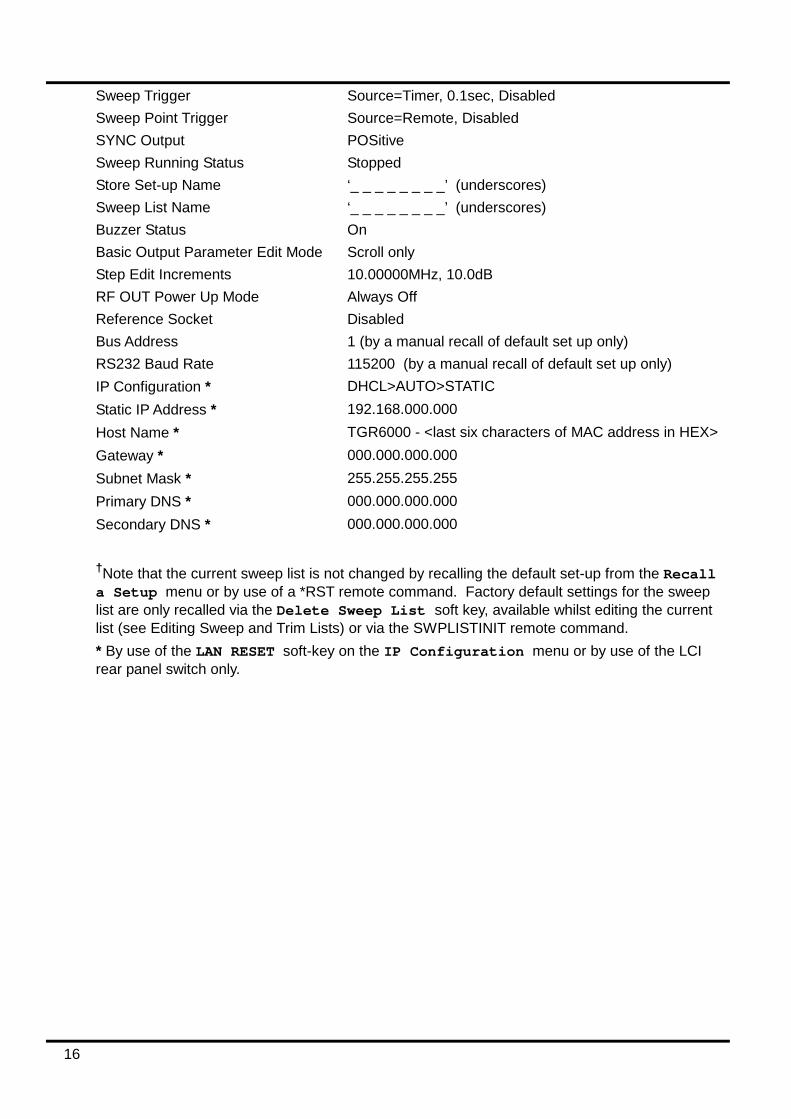
Factory Default Settings The following are the factory default settings. The instrument can be returned to these settings at any time by recalling them from Store 00 on the RECALL SETUP menu, see Utilities section. The *RST remote command will also return the instrument to these settings, with the exception of the interface specific settings. Basic output frequency 6000.00000MHz Basic output level -10.0dBm Level Trim Disabled Level Trim list Single point set to 10.00000MHz, 0.0dB Sweep Type Step Sweep Sweep Start 10.00000MHz, 0.0dBm Sweep Stop 6000.00000MHz, -50dBm Sweep Scale Linear Number of Step Sweep Points 11 Step Sweep Dwell 300msec
Sweep List†
A single point set to 6000.00000MHz, -110dBm, 0.010s dwell.
Sweep Mode Frequency + Level, single sweep Sweep Direction Up Sweep Status Display On
16
Sweep Trigger Source=Timer, 0.1sec, Disabled Sweep Point Trigger Source=Remote, Disabled SYNC Output POSitive Sweep Running Status Stopped Store Set-up Name ‘_ _ _ _ _ _ _ _’ (underscores) Sweep List Name ‘_ _ _ _ _ _ _ _’ (underscores) Buzzer Status On Basic Output Parameter Edit Mode Scroll only Step Edit Increments 10.00000MHz, 10.0dB RF OUT Power Up Mode Always Off Reference Socket Disabled Bus Address 1 (by a manual recall of default set up only) RS232 Baud Rate 115200 (by a manual recall of default set up only) IP Configuration * DHCL>AUTO>STATIC Static IP Address * 192.168.000.000 Host Name * TGR6000 - <last six characters of MAC address in HEX> Gateway * 000.000.000.000 Subnet Mask * 255.255.255.255 Primary DNS * 000.000.000.000 Secondary DNS * 000.000.000.000 †Note that the current sweep list is not changed by recalling the default set-up from the Recall a Setup menu or by use of a *RST remote command. Factory default settings for the sweep list are only recalled via the Delete Sweep List soft key, available whilst editing the current list (see Editing Sweep and Trim Lists) or via the SWPLISTINIT remote command. * By use of the LAN RESET soft-key on the IP Configuration menu or by use of the LCI rear panel switch only.
17
Utilities The Utilities menu consists of a list of sub-menus, selectable by soft-keys on the left of the menu.
Store Pressing the Store soft-key on the UTILITIES menu gives access to the Store Setup menu, the Store Sweep List menu and the Erase menu.
Store Setup and Store Sweep List Menus These menus allow instrument setups and sweep lists to be stored in non-volatile memory. The data is saved to numbered stores. The store number is chosen by scrolling through the preselected #nn field, where #nn is the store number. An optional name label may be defined and saved with the data to aid recall identification. The name may be edited by pressing the Edit soft-key, which will give access to the EDIT SETUP NAME or EDIT SWEEP LIST NAME sub-menus. Characters in the name are editable by scrolling, see Editing Text section. The Execute soft-key will immediately store the data if the selected store does not already contain data. If the store already contains data a warning is issued and confirmation requested. The action will be cancelled by pressing the CANCEL soft-key or the BACK/Escape key.
Erase Menu This menu allows complete erasure of all setup and list stored data. Confirmation is requested before the action is completed.
Recall The Recall soft-key on the UTILITIES menu gives access to the Recall a Setup menu and the Recall a Sweep List menu.
Recall Setup and Recall Sweep List menus These menus allow instrument setups and sweep lists to be recalled from non-volatile storage. Each setup or list is stored in numbered stores. The store number is chosen by scrolling through the preselected #nn field, where #nn is the store number. As each store is selected its contents are described as -No Data- if nothing has been stored in it or by a valid name label if it contains data. Note that a valid name label could be the default _ _ _ _ _ _ _ _ label. The recall operation is performed by pressing the Execute soft-key. Confirmation is always required before the operation is completed.
Edit List Name Press the Edit List Name soft-key to call the EDIT SWEEP LIST NAME menu which allows the name of the current sweep list to be set up, see Editing Text section. The name entered will be the default name label used if the list is subsequently stored in non-volatile memory.
Set Edit Mode This utility allows the user to select the way the basic output frequency and level are edited on the Main menu.
Basic Frequency and Level Setting Mode menu On this menu the edit mode for output frequency and level may be selected as Scroll Only , Step+Scroll or Step Only by scrolling through the list. See the Editing Numeric Values section for how this selection affects the editing of the output frequency and level.

18
The step sizes are entered on the Set Increment Sizes sub-menu, accessed by pressing the Edit Step Sizes soft-key. On this sub-menu, values for frequency and level step sizes may be entered by direct numeric entry, see Editing Numeric Values section. Note that when using this menu the operation of the & and & arrow keys and the knob depends on the currently selected edit mode, as follows. If the edit mode selected is Scroll Only or Step+Scroll then a scroll edit cursor is displayed in the frequency and level size fields and the knob scrolls the character underscored by the cursor in both cases. If Scroll Only is selected the & arrow keys scroll the underscored character; in the other edit modes they increment & decrement the least significant character. If Step Only is selected then no scroll cursor is displayed and increment & decrement of the least significant character is performed by both the & arrow keys and the knob.
Ref Socket The Ref Socket utility selects the function of the reference 10MHz REF IN/OUT socket. The reference socket function is scroll selectable as Input , Output or Disabled . When the 10MHz REF IN/OUT socket is selected as an input and a 10MHz signal of the specified amplitude is presented to the socket the internal reference frequency source is switched automatically from the internal oscillator to the external source and the front panel EXT REF indicator is lit. Removal of the external source causes the reference frequency source to switch back to the internal oscillator. The input impedance is 50Ω. When the 10MHz REF IN/OUT socket is selected as an output the internal oscillator is output to the socket via a 50Ω output buffer. When not to be used as an input or output, Disabled ensures no disturbance from an open input and no unwanted 10MHz radiation from an open output.
Interfaces The Interfaces soft-key accesses the INTERFACES CONFIG menu, which gives access to sub menus for setting up various remote interface functionality. The BUS ADDRESS soft-key allows the instrument to be allocated a unique bus address. The RS232 Baud rate can be adjusted via the RS232 Baud soft-key. The LAN interface can be set up and status monitored via the LAN soft-key. Further information is given in the Remote Interface Operation section.
Buzzer This utility allows the internal warning buzzer to be disabled for quiet operation.
Power Up Mode The Power Up Mode soft-key accesses the RF POWER UP MODE menu which allows the RF OUT setting at power up to be set to Always OFF (the factory default) , Always ON , or Same as Power Down.
Version Info The individual version numbers of the firmware in the internal modules is displayed via this utility.
Calibration This soft-key accesses the calibration utility for the instrument. Calibration requires specialist equipment and this facility should not be accessed without reference to the Service Guide, see Maintenance section.

19
Remote Interface Operation The instrument can be remotely controlled via its RS232, USB, LAN or optional GPIB interfaces. USB remote control operates in a similar way to RS232 but via the USB connector. Software supplied with the instrument sets up the controlling computer to treat the USB connection as a virtual COM port. Application software on the computer can then access the instrument via that COM port. Remote control using the LAN interface is possible using the TCP/IP Sockets protocol. The LAN interface meets the essential requirements of LXI ( Lan eXtensions for Instrumentation) version 1.2, Class C, but is not fully compliant because, for example, it does not contain a Web server. Instead, LAN configuration and status is provided via a front panel menu. All interfaces are live at all times.
Address Selection, RS232 Baud Rate and LAN status The address, Baud rate and LAN configuration are set from the instrument’s front panel as follows. Press the UTILITIES key to select the UTILITIES menu, scroll down the list of sub menus and press the Interfaces soft-key to select the INTERFACE CONFIG menu.
The BUS ADDRESS soft-key allows the instrument to be allocated a unique bus address bus. The address can be decremented and incremented in the range 1 to 31 inclusive (not 0), with 'wrap-round'. The instrument address capability is strictly required only by the GPIB interface but use can be made of the ADDRESS? command over any of the interfaces to easily identify which instrument is being controlled by a particular COM port (for RS232 or USB) or TCP socket (for LAN). The RS232 Baud rate can be adjusted via the RS232 Baud soft-key.
The LAN interface status can be monitored, and the set-up modified, via the LAN Status menu which is accessed by pressing the LAN soft-key. The status is given at the top of the display and will be either NO LAN (LAN not connected), CONFIGURE (instrument attempting to make a connection via DHCP, Auto-IP or by assigning a Static IP address), or CONNECTED (LAN connection made). See the LAN Interface section for full configuration details.
Remote/Local Operation At power-on the instrument will be in the local state with the REMOTE indicator off. In this state all front panel operations are possible. When a command is received the remote state will be entered and REMOTE will be turned on. In this state the front panel is locked out and remote commands only will be processed. The instrument may be returned to the local state by pressing the Local key; however, the effect of this action will only remain until the instrument is addressed again or receives another character from the interface, when the remote state will once again be entered. Returning to Local by this action, or by the use of the LOCAL command, will keep the settings at their last remotely set values.

20
RS232 Interface RS232 Interface Connector
The 9-way D-type serial interface connector is located on the instrument rear panel. The pin connections are as shown below:
Pin Name Description 1 RI Passively asserted (+V through 10kΩ) 2 TXD Transmitted data from instrument 3 RXD Received data to instrument 4 CTS 5 GND Signal ground 6 RTS Passively asserted (+V through 10kΩ) 7 DSR No internal connection 8 DTR 9 CD No internal connection
RS232 Connections The RS232 interface should be connected to a standard PC port using a fully wired 1:1 male-female cable without any cross-over connections. Alternatively, only pins 2, 3 and 5 need be connected to the PC, but with links made in the connector at the PC end between pins 1, 4 and 6 and between pins 7 and 8, see diagram.
Baud Rate for this instrument can be set from 1200 to 115200; the other parameters are fixed as follows:
Start Bits: 1 Parity: None Data Bits: 8 Stop Bits: 1
RS232 Character Set Because of the need for XON/XOFF handshake it is possible to send ASCII coded data only; binary blocks are not allowed. Bit 7 of ASCII codes is ignored, i.e. assumed to be low. No distinction is made between upper and lower case characters in command mnemonics and they may be freely mixed. The ASCII codes below 20H (space) are not used. In this manual 20H, etc. means 20 in hexadecimal. The unit will send XOFF when there are 50 free bytes remaining and XON when this increases to 100 bytes.

21
USB Interface The USB interface is a virtual COM port which can be controlled by a PC as if it was a RS232 device. The instrument is supplied with a CD containing an .inf file for the standard Microsoft drivers available in Windows 2000, XP, Vista and Windows 7; the installation wizard will install the driver (32-bit or 64-bit) appropriate to the PC’s operating system. Any updates are available via the TTi website, http://www.aimtti.com/support. Installation of the interface driver is achieved by connecting the instrument to a PC via a standard USB cable. The Windows’ plug and play functions should automatically recognise the addition of new hardware attached to the USB interface and, if this is the first time the connection has been made, prompt for the location of a suitable driver. Provided that the standard Windows prompts are followed correctly Windows will install the appropriate driver and establish a virtual COM port within the PC. The number of the new COM port will depend upon the number of co-existing COM ports within the PC. The virtual COM port can be driven by Windows applications in exactly the same way as a standard COM port, except that the Baud rate setting of the virtual COM port is ignored. The driver will remain installed on the PC so that the establishment of a virtual COM port is done automatically each time the instrument is connected to the PC via USB in the future. Further virtual COM ports are created for each additional instrument connected to the PC via USB. Each instrument is assigned a separate virtual COM port when it is first connected and the same COM port will be assigned each time that instrument is subsequently connected; the PC software makes use of the unique code embedded in each instrument to link it to the same virtual COM port irrespective of which physical USB port it is connected to. Use can also be made of the ADDRESS? command to easily identify which instrument is being controlled by a particular COM port. Although the addressing capability is ignored in USB operation the address can still be set and used as an identifier; set each USB-connected instrument to a different address and send the ADDRESS? command from each virtual COM port to confirm which instrument is connected to that port.
LAN Interface The LAN interface contains the interfaces and protocols described below. Since it is possible to misconfigure the LAN interface, making it impossible to communicate with the instrument over LAN, a LAN Configuration Initialise (LCI) mechanism is provided via a recessed switch on the rear panel to reset the unit to the factory default. It is also possible to reset to the factory default from the front panel by using the LAN RESET soft-key on the IP Configuration menu, see LAN Connection section for details. The default setting is for the instrument to attempt to obtain settings via DHCP if available or, if DHCP times out (30 seconds), via Auto-IP. In the very unlikely event that an Auto-IP address cannot be found a static IP address of 192.168.0.100 is assigned.
LAN Connection To use the LAN interface, the IP address of the unit must be known. There is a LXI Discovery Tool on the supplied CD-ROM which can be used to display the IP addresses (and other associated information) of all connected devices that comply with the VXI-11 discovery protocol. This tool is a Windows PC application that should be installed and run on the controlling PC with the unit either connected directly to the PC network connector or via a router. Connecting via a router is recommended as this is significantly quicker to assign an IP address; connecting directly to the PC will begin to assign an IP address only after a 30 second DHCP timeout. There are also tools for LAN discovery included as part of the National Instruments Measurement and Automation Explorer package and the Agilent Vee application. The unit will, when first powered up, attempt to obtain settings via DHCP if available or, if DHCP times out (30 seconds), via Auto-IP. In the very unlikely event that an Auto-IP address cannot be found a static IP address of 192.168.0.100 is assigned. The LAN status can be monitored during this process on the LAN Status menu; to view this menu press the Interfaces soft-key on
22
the UTILITIES menu to select the INTERFACE CONFIG menu, then the LAN soft-key to show the LAN Status menu. The status is given at the top of the display and will be either NO LAN (LAN connection not made), CONFIGURE (instrument currently attempting to make a connection via DHCP, Auto-IP or by assigning a Static IP address), or CONNECTED (LAN connection made). The LAN Status menu also gives access to the following LAN parameters. Most of these will be set automatically during DHCP or are fixed; where parameters can be modified from the keyboard this is indicated in the list below:
TCP Port Fixed at 9221 IP Config Selectable to be DHCP/Auto-IP/Static (default), or Auto-IP/Static, or Static.
The LAN parameters can also be reset to factory default on this menu IP Address Automatically assigned by DHCP/Auto-IP or user-assigned Static address Host Name User-assigned instrument identifier (default TGR6000 + part MAC address) MAC address Unique MAC address – programmed at manufacture Gateway Automatically assigned by DHCP/Auto-IP, e.g. router address. Static
gateway address can be user-set.* Subnet Mask Automatically assigned by DHCP/Auto-IP. Static mask can be user-set.* DNS-Primary Automatically assigned by DHCP/Auto-IP. Static DNS can be user-set.* DNS-Secondary Automatically assigned by DHCP/Auto-IP. Static DNS can be user-set.*
* These are parameters of the controller which can be determined by user interrogation if not established automatically, e.g. in a ‘simple’ one-to-one LAN system without a router. Note: Modified parameters are only applied after the power is turned off and back on again.
ICMP Ping Server The unit contains an ICMP server allowing the instrument to be ‘pinged’ via either its host name or IP address.
VXI-11 Discovery Protocol The instrument has very limited support of VXI-11 which is sufficient for the discovery protocol and no more. The instrument implements a Sun RPC Port-mapper on TCP port 111 and UDP port 111 as defined in RPC1183. The calls supported are: NULL, GET PORT and DUMP. On TCP port 1024 a very simple VXI-11 protocol is implemented sufficient only for instrument discovery. This implements the following calls: CREATE LINK, DEVICE_WRITE, DEVICE_READ and DESTROY_LINK. Once a link has been created anything written to the device is ignored and any read from the device returns the identification string as would be expected from a “*IDN?” of the form ‘Manufacturer,Model,Serial No.,X.xx Y.yy Z.zz’ for example THURLBY THANDAR,TGR6000,345678,1.00 1.00 1.00 where ‘X.xx’ is the revision of the Control firmware, ‘Y.yy’ is the revision of the RF firmware and ‘Z.zz’ is the revision of the interface firmware. Firmware is user field updateable via the USB port.
VISA Resource Name Because of the limited support for VXI-11(Discovery Protocol only), the instrument must be referred to by its raw socket information when used in software packages which communicate via a VISA resource name. For example, an instrument at IP address 192.168.1.100 would normally have a VISA resource name of "TCPIP0::192.168.1.100::inst0::INSTR" but for this instrument the name must be modified to read "TCPIP0::192.168.1.100::9221::SOCKET" where 9221 is the TCP port used by this instrument for control and monitoring, see below.
23
TCP Sockets The instrument uses 1 socket on TCP port 9221 for instrument control and monitoring. Text commands are sent to this port as defined in ‘Remote Commands’ and any replies are returned via the same port.
LAN Error If a LAN connection is made but an error is detected (e.g. the IP address is the same as another device on the network) then the LAN status menu will show NO LAN until the error is corrected, see LAN Connection section. If a LAN error occurs; check and correct the configuration of the instrument; a LAN Configuration Initialise (LCI) mechanism is provided via a recessed switch on the rear panel ( marked LAN RESET) or the keyboard (see LAN connection section) to reset the unit to the factory default. The default setting is for the instrument to attempt to obtain settings via DHCP if available or, if DHCP times out (30 seconds), via Auto-IP. In the very unlikely event that an Auto-IP address cannot be found a static IP address of 192.168.0.100 is assigned. If no physical LAN connection is found at any time then the LAN status will continue to be reported as NO LAN on the the LAN status menu.
GPIB Interface The GPIB interface 24-way connector is located on the instrument rear panel. The pin connections are as specified in IEEE Std. 488.1-1987 and the instrument complies with IEEE Std. 488.1-1987 and IEEE Std. 488.2-1987.
GPIB Subsets This instrument contains the following IEEE 488.1 subsets:
Source Handshake SH1 Acceptor Handshake AH1 Talker T6 Listener L4 Service Request SR1 Remote Local RL2 Parallel Poll PP1 Device Clear DC1 Device Trigger DT0 Controller C0 Electrical Interface E2
GPIB IEEE Std. 488.2 Error Handling – Query Error Register The IEEE 488.2 UNTERMINATED error (addressed to talk with nothing to say) is handled as follows. If the instrument is addressed to talk and the response formatter is inactive and the input queue is empty then the UNTERMINATED error is generated. This will cause the Query Error bit to be set in the Standard Event Status Register, a value of 3 to be placed in the Query Error Register and the parser to be reset. See the Status Reporting section for further information. The IEEE 488.2 INTERRUPTED error is handled as follows. If the response formatter is waiting to send a response message and a <PROGRAM MESSAGE TERMINATOR> has been read by the parser or the input queue contains more than one END message then the instrument has been INTERRUPTED and an error is generated. This will cause the Query Error bit to be set in the Standard Event Status Register, a value of 1 to be placed in the Query Error Register and the response formatter to be reset thus clearing the output queue. The parser will then start parsing the next <PROGRAM MESSAGE UNIT> from the input queue. See the Status Reporting section for further information.
24
The IEEE 488.2 DEADLOCK error is handled as follows. If the response formatter is waiting to send a response message and the input queue becomes full then the instrument enters the DEADLOCK state and an error is generated. This will cause the Query Error bit to be set in the Standard Event Status Register, a value of 2 to be placed in the Query Error Register and the response formatter to be reset thus clearing the output queue. The parser will then start parsing the next <PROGRAM MESSAGE UNIT> from the input queue. See the Status Reporting section for further information.
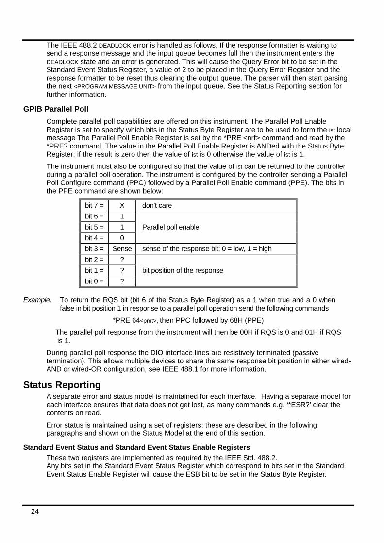
GPIB Parallel Poll Complete parallel poll capabilities are offered on this instrument. The Parallel Poll Enable Register is set to specify which bits in the Status Byte Register are to be used to form the ist local message The Parallel Poll Enable Register is set by the *PRE <nrf> command and read by the *PRE? command. The value in the Parallel Poll Enable Register is ANDed with the Status Byte Register; if the result is zero then the value of ist is 0 otherwise the value of ist is 1. The instrument must also be configured so that the value of ist can be returned to the controller during a parallel poll operation. The instrument is configured by the controller sending a Parallel Poll Configure command (PPC) followed by a Parallel Poll Enable command (PPE). The bits in the PPE command are shown below:
bit 7 = X don't care bit 6 = 1 bit 5 = 1 Parallel poll enable bit 4 = 0 bit 3 = Sense sense of the response bit; 0 = low, 1 = high bit 2 = ? bit 1 = ? bit position of the response bit 0 = ?
Example. To return the RQS bit (bit 6 of the Status Byte Register) as a 1 when true and a 0 when false in bit position 1 in response to a parallel poll operation send the following commands
*PRE 64<pmt>, then PPC followed by 68H (PPE) The parallel poll response from the instrument will then be 00H if RQS is 0 and 01H if RQS is 1.
During parallel poll response the DIO interface lines are resistively terminated (passive termination). This allows multiple devices to share the same response bit position in either wired-AND or wired-OR configuration, see IEEE 488.1 for more information.
Status Reporting A separate error and status model is maintained for each interface. Having a separate model for each interface ensures that data does not get lost, as many commands e.g. ‘*ESR?’ clear the contents on read. Error status is maintained using a set of registers; these are described in the following paragraphs and shown on the Status Model at the end of this section.
Standard Event Status and Standard Event Status Enable Registers These two registers are implemented as required by the IEEE Std. 488.2. Any bits set in the Standard Event Status Register which correspond to bits set in the Standard Event Status Enable Register will cause the ESB bit to be set in the Status Byte Register.
25
The Standard Event Status Register is read and cleared by the *ESR? command. The Standard Event Status Enable register is set by the *ESE <nrf> command and read by the *ESE? command. It is a bit field where each bit has the following significance. Bit 7: Power On. Set when power is first applied to the instrument. Bit 6: Not used. Bit 5: Command Error. Set when a syntax type error is detected in a command from the bus.
The parser is reset and parsing continues at the next byte in the input stream Bit 4: Execution Error. Set when an error is encountered while attempting to execute a
completely parsed command. The appropriate error number will be reported in the Execution Error Register, see Error Messages section
Bit 3: Not used. Bit 2: Query Error. Set when a query occurs. The appropriate error number will be reported
in the Query Error Register, see Query Error Register section. Bit 1: Not used. Bit 0: Operation Complete: Set in response to the ‘*OPC’ command.
Execution Error Register This register contains a number representing the last error encountered over the current interface. The Execution Error Register is read and cleared using the ‘EER?’ command. On power up this register is set to 0 for all interface instances. Error messages have the following meaning: 0: No error encountered 120: Numeric value sent was out of range. 123: Internal error reported when preparing Flash for erase or write. Probable hardware fault. 124: Internal error reported when writing to Flash. Probable hardware fault. 125: Internal error reported when erasing Flash. Probable hardware fault. 126: An error has been encountered in the data of a set-up store 127: An error has been encountered in the data of a List Sweep store 128: No valid data in the requested set-up store or List Sweep store. 134: Running the sweep is inhibited because the calculated output level with TRIM added is
>+7dBm or <-110dBm at point nnnn in the sweep. (nnnn is shown briefly in the display) 135: An attempt to change a parameter value is illegal because sweep is running. 136: An attempt to change a TRIM parameter is illegal because TRIM is currently active. Note that for some of the above errors a self-explanatory message is also shown briefly
in the display.
Status Byte Register and Service Request Enable Register These two registers are implemented as required by the IEEE Std. 488.2. Any bits set in the Status Byte Register which correspond to bits set in the Service Request Enable Register will cause the RQS/MSS bit to be set in the Status Byte Register, thus generating a Service Request on the bus. The Status Byte Register is read either by the *STB? command, which will return MSS in bit 6, or by a Serial Poll which will return RQS in bit 6. The Service Request Enable register is set by the *SRE <nrf> command and read by the *SRE? command.
26
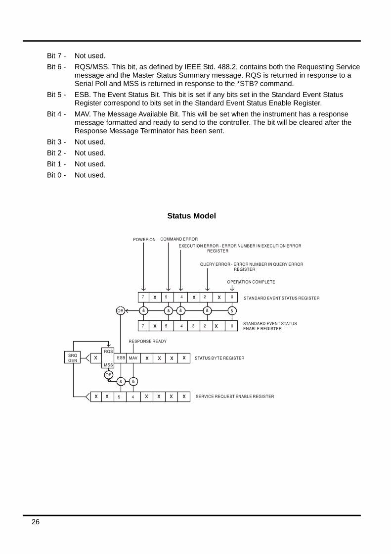
Bit 7 - Not used. Bit 6 - RQS/MSS. This bit, as defined by IEEE Std. 488.2, contains both the Requesting Service
message and the Master Status Summary message. RQS is returned in response to a Serial Poll and MSS is returned in response to the *STB? command.
Bit 5 - ESB. The Event Status Bit. This bit is set if any bits set in the Standard Event Status Register correspond to bits set in the Standard Event Status Enable Register.
Bit 4 - MAV. The Message Available Bit. This will be set when the instrument has a response message formatted and ready to send to the controller. The bit will be cleared after the Response Message Terminator has been sent.
Bit 3 - Not used. Bit 2 - Not used. Bit 1 - Not used. Bit 0 - Not used.
Status Model

27
Power-on and Remote Operation Default Settings The following instrument status values are set at power on:
Status Byte Register = 0 Service Request Enable Register † = 0 Standard Event Status Register = 128 (pon bit set) Standard Event Status Enable Register † = 0 Execution Error Register = 0 Query Error Register = 0 Parallel Poll Enable Register † = 0
† Registers marked thus are specific to the GPIB section of the instrument and are of limited use via other interfaces. The instrument will be in local state with the front panel controls active. The instrument parameters at power-on are the same as at last switch off with the exception of the RF OUT status. By default this is always off at power on but the user may change this from the front panel to be always on, or the same at power on as at power off, see Utilities section. The *RST (reset) interface command resets the instrument to the Remote Operation Default settings. The Remote Operation Default settings are the same as the Factory Default settings with the exception that *RST does not change any interface settings (address, Baud rate, LAN settings) or the contents of the sweep list. See Factory Default Settings section for further details.
28
Remote Commands Remote Command Format
RS232 input to the instrument is buffered in a 256 byte input queue which is filled, under interrupt, in a manner transparent to all other instrument operations. The instrument will send XOFF when approximately 200 characters are in the queue. XON will be sent when approximately 100 free spaces become available in the queue after XOFF was sent. This queue contains raw (un-parsed) data which is taken, by the parser, as required. Commands (and queries) are executed in order and the parser will not start a new command until any previous command or query is complete. RS232 responses to commands or queries are sent immediately; there is no output queue. USB input conforms with USB 2.0 Full Speed. Commands must be sent as specified in the commands list and must be terminated with the command terminator code 0AH (Line Feed, LF). Commands may be sent in groups with individual commands separated from each other by the code 3BH (;). The group must be terminated with command terminator 0AH (Line Feed, LF). Responses from the instrument to the controller are sent as specified in the commands list. Each response is terminated by a <RESPONSE MESSAGE TERMINATOR> which is 0DH (Carriage Return, CR) followed by 0AH (Line Feed, LF). <WHITE SPACE> is defined as character codes 00H to 20H inclusive. <WHITE SPACE> is ignored except in command identifiers. e.g. '*C LS' is not equivalent to '*CLS'. The high bit of all characters is ignored. The commands are case insensitive.
GPIB Remote Command Format GPIB input to the instrument is buffered in a 256 byte input queue which is filled, under interrupt, in a manner transparent to all other instrument operations. The queue contains raw (un-parsed) data which is taken, by the parser, as required. Commands (and queries) are executed in order and the parser will not start a new command until any previous command or query is complete. There is no output queue which means that the response formatter will wait, indefinitely if necessary, until the instrument is addressed to talk and the complete response message has been sent, before the parser is allowed to start the next command in the input queue. Commands are sent as <PROGRAM MESSAGES> by the controller, each message consisting of zero or more <PROGRAM MESSAGE UNIT> elements separated by <PROGRAM MESSAGE UNIT SEPARATOR> elements. A <PROGRAM MESSAGE UNIT> is any of the commands in the remote commands list. A <PROGRAM MESSAGE UNIT SEPARATOR> is the semi-colon character ';' (3BH). <PROGRAM MESSAGES> are separated by <PROGRAM MESSAGE TERMINATOR> elements which may be any of the following: NL The new line character (0AH) NL^END The new line character with the END message ^END The END message with the last character of the message Responses from the instrument to the controller are sent as <RESPONSE MESSAGES>. A <RESPONSE MESSAGE> consists of one <RESPONSE MESSAGE UNIT> followed by a <RESPONSE MESSAGE TERMINATOR>. A <RESPONSE MESSAGE TERMINATOR> is the new line character with the END message NL^END. Each query produces a specific <RESPONSE MESSAGE> which is listed along with the command in the remote commands list. <WHITE SPACE> is ignored except in command identifiers. e.g. '*C LS' is not equivalent to '*CLS'. <WHITE SPACE> is defined as character codes 00H to 20H inclusive with the exception of the NL character (0AH). The high bit of all characters is ignored. The commands are case insensitive.

29
Command List This section lists all commands and queries implemented in this instrument. The commands are listed in alphabetical order within the function groups. Note that there are no dependent parameters, coupled parameters, overlapping commands, expression program data elements or compound command program headers; each command is completely executed before the next command is started. All commands are sequential and the operation complete message is generated immediately after execution in all cases. The following nomenclature is used:
<rmt> <RESPONSE MESSAGE TERMINATOR>
<cpd> <CHARACTER PROGRAM DATA>, i.e. a short mnemonic or string such as ON or OFF.
<nrf> A number in any format. e.g. 12, 12.00, 1.2 e1 and 120 e-1 are all accepted as the number 12. Any number, when received, is converted to the required precision consistent with the use then rounded up to obtain the value of the command.
<nr1> A number with no fractional part, i.e. an integer. The commands which begin with a ∗ are those specified by IEEE Std. 488.2 as Common commands. All will function when used on the other interfaces but some are of little use.
Output Parameters FREQ <nrf> Set the output frequency to <nrf> MHz UVLEV <nrf> Set the output level to <nrf> in uV MVLEV <nrf> Set the output level to <nrf> in mV DBMLEV <nrf> Set the output level to <nrf> in dBm DBUVLEV <nrf> Set the output level to <nrf> in dBuV RFON Switch on RF output RFOFF Switch off RF output RFOUT <cpd> Set the output to <ON> or <OFF> (alternative command to RFON & RFOFF)
LIST Sweep Settings SWPLISTSET <nrf><csv ascii data>
Downloads a complete Sweep List, overwriting the existing list. <nrf> is the number of points in the list and the following <csv ascii data> consists of ,<nrf>,<nrf>,<nrf> for each point in the list where these are frequency (MHz), level (dBm)and dwell (ms) respectively.
SWPPOINTSET <nrf>,<nrf>,<nrf>,<nrf>
Sets the values of a specified point in the Sweep List where the <nrf> values are point number, frequency (MHz), level (dBm), dwell (ms). If the point number is greater than the highest point number of the existing Sweep List the intervening points will be filled with the same values as the original highest point.
SWPCOPY Copies the current Step Sweep points to the Sweep List (overwrites old list) SWPLISTINIT Initialises the Sweep List to a single point (6000MHz, -110dBm, 10ms dwell)
30
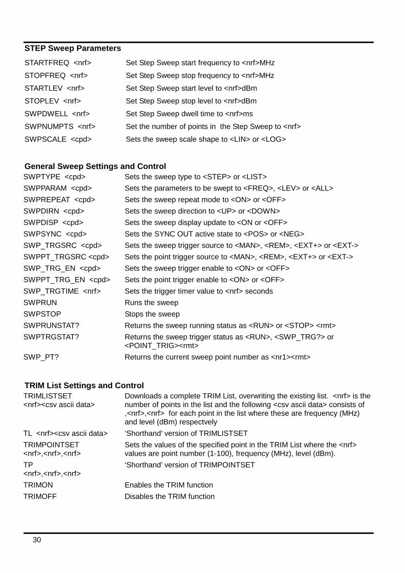
STEP Sweep Parameters STARTFREQ <nrf> Set Step Sweep start frequency to <nrf>MHz STOPFREQ <nrf> Set Step Sweep stop frequency to <nrf>MHz STARTLEV <nrf> Set Step Sweep start level to <nrf>dBm STOPLEV <nrf> Set Step Sweep stop level to <nrf>dBm SWPDWELL <nrf> Set Step Sweep dwell time to <nrf>ms SWPNUMPTS <nrf> Set the number of points in the Step Sweep to <nrf> SWPSCALE <cpd> Sets the sweep scale shape to <LIN> or <LOG>
General Sweep Settings and Control SWPTYPE <cpd> Sets the sweep type to <STEP> or <LIST> SWPPARAM <cpd> Sets the parameters to be swept to <FREQ>, <LEV> or <ALL> SWPREPEAT <cpd> Sets the sweep repeat mode to <ON> or <OFF> SWPDIRN <cpd> Sets the sweep direction to <UP> or <DOWN> SWPDISP <cpd> Sets the sweep display update to <ON or <OFF> SWPSYNC <cpd> Sets the SYNC OUT active state to <POS> or <NEG> SWP_TRGSRC <cpd> Sets the sweep trigger source to <MAN>, <REM>, <EXT+> or <EXT-> SWPPT_TRGSRC <cpd> Sets the point trigger source to <MAN>, <REM>, <EXT+> or <EXT-> SWP_TRG_EN <cpd> Sets the sweep trigger enable to <ON> or <OFF> SWPPT_TRG_EN <cpd> Sets the point trigger enable to <ON> or <OFF> SWP_TRGTIME <nrf> Sets the trigger timer value to <nrf> seconds SWPRUN Runs the sweep SWPSTOP Stops the sweep SWPRUNSTAT? Returns the sweep running status as <RUN> or <STOP> <rmt> SWPTRGSTAT? Returns the sweep trigger status as <RUN>, <SWP_TRG?> or
<POINT_TRIG><rmt> SWP_PT? Returns the current sweep point number as <nr1><rmt>
TRIM List Settings and Control TRIMLISTSET <nrf><csv ascii data>
Downloads a complete TRIM List, overwriting the existing list. <nrf> is the number of points in the list and the following <csv ascii data> consists of ,<nrf>,<nrf> for each point in the list where these are frequency (MHz) and level (dBm) respectvely
TL <nrf><csv ascii data> ‘Shorthand’ version of TRIMLISTSET TRIMPOINTSET <nrf>,<nrf>,<nrf>
Sets the values of the specified point in the TRIM List where the <nrf> values are point number (1-100), frequency (MHz), level (dBm).
TP <nrf>,<nrf>,<nrf>
‘Shorthand’ version of TRIMPOINTSET
TRIMON Enables the TRIM function TRIMOFF Disables the TRIM function

31
System Commands ∗RST Resets the instrument to default settings with the exception of all remote
interface settings. SAVESETUP <nr1> Save Set-up to set-up store <nr1> SAVELIST <nr1> Save List to List store <nr1> RCLSETUP <nr1> Recall Set-up from Set-up store <nr1> RCLLIST <nr1> Recall List from List store <nr1> LOCAL Returns the instrument to local operation and unlocks the keyboard. ADDRESS? Returns the bus address of the instrument; This is the address used by GPIB
or may be used as a general identifier over the other interfaces. The response format is <nr1><rmt>.
PWRUPMODE <cpd> Sets the RF OUT status at power up to <ON>, <OFF> or <LAST> REFSKT <cpd> Set the reference socket to <IN>, <OUT> or <OFF>. BUZZ <cpd> Set the internal buzzer to <ON> or <OFF>. EDITMODE <cpd> Sets the frequency & level edit mode to <SCROLL>, <STEP> or <BOTH>
Status Commands EER? Query and clear Execution Error Register. The response format is
<nr1><rmt>. QER? Query and clear Query Error Register. The response format is <nr1><rmt>. ∗CLS Clear Status. Clears the Standard Event Status Register, Query Error
Register and Execution Error Register. This indirectly clears the Status Byte Register.
∗ESE <nrf> Set the Standard Event Status Enable Register to the value of <nrf>. ∗ESE? Returns the value in the Standard Event Status Enable Register in <nr1>
numeric format. The syntax of the response is <nr1><rmt>. ∗ESR? Returns the value in the Standard Event Status Register in <nr1> numeric
format. The register is then cleared. The syntax of the response is <nr1><rmt>.
∗IST? Returns ist local message as defined by IEEE Std. 488.2. The syntax of the response is 0<rmt>, if the local message is false or 1<rmt>, if the local message is true.
∗OPC Sets the Operation Complete bit (bit 0) in the Standard Event Status Register. This will happen immediately the command is executed because of the sequential nature of all operations.
∗OPC? Query Operation Complete status. The syntax of the response is 1<rmt>. The response will be available immediately the command is executed because of the sequential nature of all operations.
∗PRE <nrf> Set the Parallel Poll Enable Register to the value <nrf>. ∗PRE? Returns the value in the Parallel Poll Enable Register in <nr1> numeric
format. The syntax of the response is <nr1><rmt>. ∗SRE <nrf> Set the Service Request Enable Register to <nrf>. ∗SRE? Returns the value of the Service Request Enable Register in <nr1> numeric
format. The syntax of the response is <nr1><rmt>. ∗STB? Returns the value of the Status Byte Register in <nr1> numeric format. The
syntax of the response is <nr1><rmt>. ∗WAI Wait for Operation Complete true. As all commands are completely executed
before the next is started this command takes no additional action.

32
Miscellaneous Commands ∗IDN? Returns the instrument identification. The exact response is determined by the
instrument configuration and is of the form <NAME>,<model>, 0, <version><rmt> where <NAME> is the manufacturer’s name, <model> defines the type of instrument and <version> is the revision level of the software installed.
∗TST? The generator self-test returns the response 0 <rmt> if OK or an error code <nr1><rmt> if an error has occurred.
∗TRG Equivalent to the action of generating a trigger with the front panel TRIG key.
See Service Guide for details of calibration specific commands.

33
Maintenance The Manufacturers or their agents overseas will provide repair for any unit developing a fault. Where owner wish to undertake their own maintenance work, this should only be done by skilled personnel in conjunction with the service guide which may be purchased directly from the Manufacturers or their agents overseas.
Calibration The Manufacturers or their agents overseas can provide calibration support. Calibration requires specialist equipment and this utility should only be accessed by skilled engineers in conjunction with the Service Guide.
Cleaning
If the instrument requires cleaning use a cloth that is only lightly dampened with water or a mild detergent.
WARNING! TO AVOID ELECTRIC SHOCK, OR DAMAGE TO THE INSTRUMENT, NEVER ALLOW WATER TO GET INSIDE THE CASE. TO AVOID DAMAGE TO THE CASE NEVER CLEAN WITH SOLVENTS.
Web link For the latest version of this instruction manual, IVI driver and any applicable firmware updates go to http://www.aimtti.com/support.

Thurlby Thandar Instruments Ltd.
Glebe Road • Huntingdon • Cambridgeshire • PE29 7DR • England (United Kingdom)
Telephone: +44 (0)1480 412451 • Fax: +44 (0)1480 450409
International web site: www.aimtti.com • UK web site: www.aimtti.co.uk
Email: [email protected]
Aim Instruments and Thurlby Thandar Instruments Book Part No. 48591-1240 Iss 9