tgn (traffic generator) user manual
TRANSCRIPT
TGN (Traffic GeNerator) User Manual
Pagent Release 4.8
Cisco Company Confidential
Document Revision 1.0 Last Modified: 9/18/08

C O N T E N T S
Chapter 1 Getting Started 1
Defining and Sending TGN Packets 1
Defining and Sending TGN Packet Flows 3
Defining and Sending TGN Packet Sequences 4
Defining and Sending TGN Packets on a Mixed Interface 5
Defining and Sending TGN Packets on a Subinterface 5
Creating Packets for SRE 5
Additional TGN Commands 5
Using the Router Console or vty Port 7
TGN Command Prompt Modes 7Using Flow Mode 8Using SRE Mode 9
Using TCL Scripts 9
IOS File System 10TFTP 10RCP 10Flash 11FTP 11
Chapter 2 Command Reference 1
<1-4294967295> – Selecting a Traffic Stream by Number 1
<interface_name> – Selecting an Interface 1
L2-.... – Updating the Datalink Header Definition 1IOS-Dependent Datalink Header Update Commands 2HEX Datalink Header Update Commands 2Ethernet ARPA Encap Datalink Header Field Update Commands 2Ethernet SNAP Encap Datalink Header Field Update Commands 2Ethernet SAP Encap Datalink Header Field Update Commands 2Ethernet Novell-Ether Encap Datalink Header Field Update Commands 2Token Ring SNAP Encap Datalink Header Field Update Commands 3Token Ring SAP Encap Datalink Header Field Update Commands 3FDDI SNAP Encap Datalink Header Field Update Commands 3FDDI SAP Encap Datalink Header Field Update Commands 3Serial HDLC Datalink Header Field Update Commands 3
L3-.... – Updating the Network Header Definition 4IP Network Header Field Update Commands 4ARP Network Header Field Update Commands 4IPX Network Header Field Update Commands 5AppleTalk Phase 2 Network Header Field Update Commands 5AppleTalk Phase 1 Network Header Field Update Commands 5AARP (AppleTalk ARP) Network Header Field Update Commands 6CLNS Network Header Field Update Commands 6DECnet Network Header Field Update Commands 6
Cisco Company Confidential Contents 3
L4-.... – Updating the Transport Header Definition 7TCP Transport Header Field Update Commands 7UDP Transport Header Field Update Commands 7ICMP Transport Header Field Update Commands 7IGMP Transport Header Field Update Commands 9
layer – Replacing the Template for a Specific Layer 9IPv6 Layer Header Field Update Commands 10ICMPv6 Layer Header Field Update Commands 10
add – Adding a Traffic Stream 10
all – Updating Multiple Traffic Streams 13
bit-rate - Setting the transmission Rate in bits per second 15
broadcast – Broadcast Mode 15Effect of Broadcast Mode and all Commands on Flow Traffic Streams 15
burst – Sending Traffic Stream in Bursts 16
clear – Clearing Configurations or Counters 16
close-logfile – Closing an Open IFS Log File 17
data – Setting Data in a Data Array 17
data-length – Setting the Data Array Length 17
datalink – Specifying the Datalink Header Encapsulation 18
delayed-start – Delaying Start of Packet Generation 18
delete – Deleting One or Several Traffic Streams 19
field – Adding and Updating Configurable Fields 20
end – Exiting the TGN Command Prompt 20
expand – Expanding a Traffic Stream into Multiple Copies 20
field – Adding and Updating Configurable Fields 21
fill-pattern – Defining Data Pattern to Fill Packet 24
filter – PKTS-FILTER Command Prompt Mode 25
flow – Adding and Updating Packet Flows 25
fragmentation – Configuring IP Fragmentation 26
insert-at – Inserting a Traffic Stream 27
interval – Setting the Interval Between Sending Packets 27
isl-crc-added – Adding CRC to ISL Packets 27
layer – Replacing the Template for a Specific Layer 28
length – Setting Packet Length 28
load-config – Loading a Configuration from IFS 29
max-bit-rate – Setting Interface Bandwidth Control 30
4 TGN (Traffic GeNerator) User Manual Cisco Company Confidential
mixed-interface – Defining Traffic Streams on a Mixed Interface 30
name – Assigning a Name to a Traffic Stream 30
on/off – Activating or Deactivating a Traffic Stream 31
open-logfile – Opening an IFS Log File 31
ordered-traffic – Setting Ordered-Traffic Scheduling 32
output-mode – Setting the Output Mode 32
prompt – Setting Command Prompt Format 34
pkts – PKTS Command Prompt 34
rate – Setting the Packet Send Rate 35
repeat – Resending Packets Repeatedly 35
replace - Selectively replacing IP Address and TCP/UDP Port Number 36
save-config – Saving a Configuration to IFS 36
secondary – Selecting a SECONDARY Processor for Transmission 37
select – Selecting a Traffic Stream by Name 37
send – Sending Packets 38
sequence – Adding and Updating Packet Sequences 38
show – Displaying Traffic Stream and Summary Information 38show – Displaying a Traffic Stream or Flow Member 40show aarp – Displaying AARP Header Information 41show aarp-responder – Displaying AARP Responders 41show all – Displaying Summary of Traffic Streams or Flow Members 42show appletalk – Displaying AppleTalk Header Information 42show arp – Displaying ARP Header Information 43show arp-responder – Displaying ARP Responders 43show burst – Displaying Burst Configurations 44show clns – Displaying CLNS Header Information 44show clns-hello-generator – Displaying CLNS Hello-generators 45show config – Displaying Traffic Stream Configuration Commands 45show debug – Displaying Debugging Information for Program Developers 46show decnet – Displaying DECnet Header Information 46show decnet-hello – Displaying DECnet Hello-Generators 46show flow – Displaying Summary of Packet Flows 47show global – Displaying Global Parameters 47show fragments-sent – Displaying Number of Fragments Sent 48show icmp – Displaying ICMP Header Information 48show igmp – Displaying IGMP Header Information 48show interface – Displaying Interface Status 49show interface config – Displaying Interface Configurations 49show interface max-bit-rate – Displaying Maximum Bit Rates of Interfaces 50show interface tcl-output – Displaying Interface Info in TCL-Friendly Format 50show ip – Displaying IP Header Information 50show ipx – Displaying IPX Header Information 51show mac – Displaying MAC Addresses 51
Cisco Company Confidential Contents 5
show name – Displaying Traffic Stream Names and Delayed-Start Information 51show output-mode – Displaying Output Mode Information 52show packet – Displaying Packet Sent by Traffic Stream 52show packet fragments – Displaying IP Packet Fragments 53show pagent-format – Displaying a Packet in Pagent Format 54show program-status – Displaying Current Program Status 54show rate – Displaying Traffic Stream Rates 55show secondary – Displaying Activity Status of SECONDARY Processors 56show send – Displaying Summary of Send Process 56show sequence – Displaying Summary of Packet Sequences 57show tcp – Displaying TCP Header Information 58show traffic-stream – Displaying a Traffic Stream by Name or Number 58show udp – Displaying UDP Header Information 59
sre – Defining Traffic Streams for TGN or SRE 59
start/stop – Starting and Stopping Traffic Generation 59
variability – Defining the Variability in Packet Intervals 60
verbose - Configuring for Activity Messages 60
wait-to-release – Sierra Wait-to-Release Paktype 61
write – Writing Information to an IFS Log File 61
Chapter 3 Defining Header Field Values 1
Decimal and Hex Fields 1
MAC Address Fields 2
IP Address Fields 2
IPv6 Address Fields 3
Nested Increments 3
Automatic Setting of Length and Checksum Fields 4Token Ring RIF 4
CLNS Area Fields 5
Chapter 4 ARP-Responder and Hello-Generator Commands 1
IP ARP Responder 1
AppleTalk ARP Responder 2
VINES Hello-Generator 2
CLNS Hello-Generator 2
DECnet Hello-Generator 3
Chapter 5 Using TGN and PKTS Timestamps to Measure Latency 1
Creating a TGN Traffic Stream with a Timestamp 1
Creating a PKTS Selective Filter with a Timestamp 1
Displaying Timestamp Information 1
6 TGN (Traffic GeNerator) User Manual Cisco Company Confidential
Example of Using Timestamps 2
Appendix A Examples of Traffic Streams 1
Datalink Traffic Streams 1Example of Unknown Datalink Header with IP and TCP Headers 1Example of Ethernet with ARPA Encapsulation Traffic Stream 2Example of Ethernet with SNAP Encapsulation Traffic Stream 2Example of Ethernet with SAP Encapsulation Traffic Stream 3Example of Ethernet with Novell-Ether Encapsulation Traffic Stream 3Example of Token Ring with SNAP Encapsulation Traffic Stream 4Example of Token Ring with SAP Encapsulation Traffic Stream 4Example of FDDI with SNAP Encapsulation Traffic Stream 5Example of FDDI with SAP Encapsulation Traffic Stream 5Example of Serial HDLC Traffic Streams 6
Network Protocol Traffic Stream 6Example of IP Traffic Stream 6Example of IPX Traffic Stream 7Example of AppleTalk Phase 2 Traffic Stream 7Example of AppleTalk Phase 1 Traffic Stream 8Example of VINES Traffic Stream 9Example of CLNS Traffic Stream 9Example of DECnet Traffic Stream 10Example of XNS Traffic Stream 11Example of ARP (IP) Traffic Stream 11Example of AARP (AppleTalk ARP) Traffic Stream 12
IP Transport Protocol Traffic Streams 13Example of TCP Traffic Stream 13Example of UDP Traffic Stream 14Example of ICMP Traffic Stream 15Example of IGMP Traffic Stream 16
IPv6 Traffic Streams 17Example of IPv6 Header with Routing Header Extension 17Example of TCP over IPv6 Traffic Stream 18Example of UDP over IPv6 Traffic Stream 19Example of ICMPv6 Echo Request Message Traffic Stream 20
ARP Responder and Hello-Generator Traffic Streams 21Example of IP ARP Responder 21Example of AARP (AppleTalk ARP) Responder 21Example of VINES Hello-Generator 21Example of CLNS Hello-Generator 21Example of DECnet Hello-Generator 21
Appendix B Explanation of Fields in Headers 1
Explanation of IP Header Fields 1
Explanation of TCP Header Fields 3
Explanation of UDP Header Fields 4
Explanation of ICMP Header Fields 4
Cisco Company Confidential Contents 7
Explanation of IGMP Header Fields 5
Explanation of IPX Header Fields 6
Explanation of XNS Header Fields 7
Explanation of Vines Header Fields 9
Explanation of AppleTalk Header Fields 10
Explanation of DECnet Header Fields 11
Explanation of CLNS Header Fields 12
Explanation of IP ARP and Appletalk ARP Header Fields 14
8 TGN (Traffic GeNerator) User Manual Cisco Company Confidential
C H A P T E R
Cisco Company Confidential Getting Starte
1
Getting Started
The Pagent Traffic GeNerator (TGN) is an IOS-based program in the Pagent test tool set. It defines and sends packets on any combination of supported interfaces on a router.
TGN has predefined templates for specific packet types. Packet definitions can also be imported from the PKTS program capture buffer.
TGN also provides IP ARP and AppleTalk ARP responders, in addition to VINES, DECnet, and CLNS end-node hello generators, so that the routers under test can forward packets.
Defining and Sending TGN PacketsThe following list is an overview of what is involved in using TGN to define and send packets. For more information on a particular procedure, refer to the references provided.
1 Select and load the appropriate Pagent image onto your router.
2 Select the interface you want to send packets on. Make sure the interface is “not shut.” Use show interface to see the current status of the interfaces.
<interface_name> – Selecting an Interface (page 2-1) show interface – Displaying Interface Status (page 2-49)
3 Create traffic streams using the add or insert-at commands. Each traffic stream can be thought of as a separate process to create specific types of packets and send the packets in a specific way. You can add as many traffic streams as the router memory allows. You can create traffic streams for any number of supported interfaces.
add – Adding a Traffic Stream (page 2-10) insert-at – Inserting a Traffic Stream (page 2-27)
You can create traffic streams based on packets in the PKTS program capture buffer. Both add and insert-at support this.
You can also create traffic streams by cloning existing ones, using the add or insert-at commands.
4 Use the TGN command prompt to get the current status of the program.
TGN Command Prompt Modes (page 1-7)
5 Select a traffic stream for update by entering its number.
<1-4294967295> – Selecting a Traffic Stream by Number (page 2-1)
6 Update information in the traffic stream header fields. Decimal, hex, mac address, and ip address fields are supported. With a few exceptions, almost all header fields can be set to be constant,
d 1-1
Defining and Sending TGN Packets
incrementing, or random. The L2 commands update datalink header fields. The L3 commands update network header fields. The L4 commands update transport header fields.
Decimal and Hex Fields (page 3-1) MAC Address Fields (page 3-2) IP Address Fields (page 3-2) L2-.... – Updating the Datalink Header Definition (page 2-1) L3-.... – Updating the Network Header Definition (page 2-4) L4-.... – Updating the Transport Header Definition (page 2-7)
7 You can nest incrementing header fields, which means that one field increments only when the incrementing field it links to has gone through its entire range. This ensures that all combinations of the incrementing field values are generated.
Nested Increments (page 3-3)
8 You can set header length fields and IP checksum fields automatically to their correct values.
Automatic Setting of Length and Checksum Fields (page 3-4)
9 You can define in hex the data that comes after the headers.
data – Setting Data in a Data Array (page 2-17) data-length – Setting the Data Array Length (page 2-17)
10 Complete a packet to its requested length with a fill pattern.
fill-pattern – Defining Data Pattern to Fill Packet (page 2-24)
11 Use the length command to define the traffic stream packet lengths, which can be set automatically, or they can be set to constant, incrementing, or random.
length – Setting Packet Length (page 2-28)
12 You can define the traffic stream send rate in packets per second using the rate command, or in bits per second using bit-rate command, or in milliseconds between packets using the interval command.
rate – Setting the Packet Send Rate (page 2-35) bit-rate - Setting the transmission Rate in bits per second (page 2-15) interval – Setting the Interval Between Sending Packets (page 2-27)
13 Select one of the following output-modes: process (slowest), fast (default), dedicated (fastest), or optimal (this hardware-specific superfast mode is available on some processors, but has limitations on packet definitions).
ordered-traffic – Setting Ordered-Traffic Scheduling (page 2-32)
14 When a traffic stream is started, the first packet transmission is delayed by a random value within the packet transmit interval. If there are multiple traffic streams, this prevents all packets from being sent out in bursts. You can use the delay-start command to define in milliseconds, microseconds, or nanoseconds how long the traffic stream waits after the start command before sending its first packet.
datalink – Specifying the Datalink Header Encapsulation (page 2-18)
15 If you are creating an ISL packet, you need to use the isl-crc-added command to complete the packet with a CRC over the encapsulated packet.
isl-crc-added – Adding CRC to ISL Packets (page 2-27)
16 To temporarily turn off a traffic stream, use the off command.
on/off – Activating or Deactivating a Traffic Stream (page 2-31)
TGN (Traffic GeNerator) User Manual Cisco Company Confidential1-2
Defining and Sending TGN Packet Flows
17 Use the start and stop commands to start and stop traffic generation. The s command toggles between the two states. The start send command causes traffic streams with defined send amounts to send the specified number of packets.
start/stop – Starting and Stopping Traffic Generation (page 2-59) send – Sending Packets (page 2-38)
18 Some IOS hardware is implemented with a PRIMARY processor and multiple SECONDARY processors, for example the RSP (PRIMARY processor) with VIPs (SECONDARY processors). On this hardware, either the PRIMARY processor or the SECONDARY processor (this is the default) can transmit the packets.
secondary – Selecting a SECONDARY Processor for Transmission (page 2-37) show secondary – Displaying Activity Status of SECONDARY Processors (page 2-56)
19 There are many summary commands that give an overview of traffic stream configurations. Use the show command to review the current traffic stream configuration. The show packet command displays what a packet looks like, as defined by a traffic stream configuration. The show pagent-format displays a packet in a format that can be input to the classic Pagent program.
show – Displaying Traffic Stream and Summary Information (page 2-38) show packet – Displaying Packet Sent by Traffic Stream (page 2-52) show pagent-format – Displaying a Packet in Pagent Format (page 2-54)
20 Use the all option to update all traffic steams on an interface or a subset of them.
all – Updating Multiple Traffic Streams (page 2-13)
21 Use the broadcast mode to update and review all traffic streams on all interfaces with a single command.
bit-rate - Setting the transmission Rate in bits per second (page 2-15)
Defining and Sending TGN Packet FlowsTGN packet flows are special traffic streams comprised of packets that must be transmitted in the order configured. Each flow has members. The following summarizes the steps involved in defining and sending packet flows. For more information on a particular procedure, refer to the references provided.
1 Use the add flow command to add a traffic stream containing a flow of packets.
add – Adding a Traffic Stream (page 2-10)
2 Use the flow command to add and configure flow members.
flow – Adding and Updating Packet Flows (page 2-25)
You can use flow mode or flow commands to add and configure flow members. The flow mode prompt and flow commands are available only when the currently selected traffic stream is a flow traffic stream. To get into flow mode, select a flow traffic stream and enter the flow command.
<1-4294967295> – Selecting a Traffic Stream by Number (page 2-1) Using Flow Mode (page 1-8)
3 Use the start and start send commands to start traffic generation.
Use the stop and s commands to stop or toggle the traffic generation.
start/stop – Starting and Stopping Traffic Generation (page 2-59)
Cisco Company Confidential Getting Started 1-3
Defining and Sending TGN Packet Sequences
4 In flow mode, use the show command to display individual flow members or a summary of flow packets.
show – Displaying Traffic Stream and Summary Information (page 2-38)
In TGN mode, use the show flow to display a summary of packet flows.
show flow – Displaying Summary of Packet Flows (page 2-47)
Defining and Sending TGN Packet Sequences
Note Packet flows are designed to replace TGN packet sequences, so use TGN packet flows instead of packet sequences. (Packet sequences will not be developed further and are being maintained for backward compatibility only.) See Defining and Sending TGN Packet Flows, (page 1-3). There are a number of advantages to packet flows over sequences. Packet flows offer an unequal intermember interval (which can be random), and you can specify a delayed start for the flow. You can configure and view flow members separately as a group, since each flow maintains it own list of members. Sequence items are part of a traffic stream list.
Packet sequences are special traffic streams comprised of packets that must be transmitted in the order configured. The following summarizes the steps involved in defining and sending packet sequences. For more information on a particular procedure, refer to the references provided.
1 Define a regular traffic stream that contains definitions of packets.
Defining and Sending TGN Packets (page 1-1)
2 Use the add sequence command to add a traffic stream containing a sequence of packets.
add – Adding a Traffic Stream (page 2-10)
3 Use the sequence add command to build a list of references to traffic streams with packet definitions. Use the sequence insert-at command to add a reference into an existing sequence.
With the sequence command, you can modify the sequence list by removing or disabling specific references. Use the sequence interval command to specify the interval between consecutive packets in the sequence.
sequence – Adding and Updating Packet Sequences (page 2-38)
4 Use the start and start send commands to start traffic generation. If a sequence list references a traffic stream, it is deactivated and cannot be used by another sequence list. Active traffic streams not used by a sequence list are scheduled and transmitted as usual.
The scheduling information (for example, rate and send) of the first packet in the sequence is applied to the entire sequence. Use the stop and s commands to stop or toggle the traffic generation.
start/stop – Starting and Stopping Traffic Generation (page 2-59)
5 Use the show sequence command to display a summary of packet sequences.
show sequence – Displaying Summary of Packet Sequences (page 2-57)
TGN (Traffic GeNerator) User Manual Cisco Company Confidential1-4
Defining and Sending TGN Packets on a Mixed Interface
Defining and Sending TGN Packets on a Mixed InterfaceIn TGN mixed interface mode, traffic streams across different interfaces are organized in a single list. Currently, this mode only supports process and fast-send output mode. The following summarizes the steps involved in defining and sending packets on a mixed interface. For more information on a particular procedure, refer to the references provided.
1 Turn on mixed interface mode.
mixed-interface – Defining Traffic Streams on a Mixed Interface (page 2-30)
2 Select the interface you want to send packets on.
3 Define and send regular traffic streams that contain definitions of packets.
Defining and Sending TGN Packets (page 1-1)
Traffic streams defined in mixed interface mode can only be sent using mixed interface mode. The TGN command prompt indicates whether mixed interface mode is on by adding an X to the application name (TGN-X).
Mixed interface mode is particularly useful when scheduling traffic streams that are interdependent. The default scheduling for mixed interface is ordered traffic (see ordered-traffic – Setting Ordered-Traffic Scheduling (page 2-32)).
Defining and Sending TGN Packets on a SubinterfaceBy default, the datalink header is assembled with user-defined header field values. For a subset of built-in packet templates (currently only IP-based protocol header templates), you can use the datalink command to automatically assemble the datalink header according to the interface or subinterface configuration on the router.
1 Define regular traffic streams that contain definitions of packets.
Defining and Sending TGN Packets (page 1-1)
2 Set the datalink header, IOS-dependent encapsulation with the subinterface name.
datalink – Specifying the Datalink Header Encapsulation (page 2-18)
Creating Packets for SRETGN allows you to create packets that can be used by SRE (Stimulus Response Engine). To define packets for SRE use, use the sre on command to select the mode that allows definition of packets for SRE use. You must assign SRE packets a name, since that is how SRE accesses the packet definition.
sre – Defining Traffic Streams for TGN or SRE (page 2-59) name – Assigning a Name to a Traffic Stream (page 2-30)
Additional TGN CommandsThe following commands provide additional flexibility and customization when using TGN.
• TGN allows you to define your own configurable fields in a traffic stream. These fields are given a name, can be placed anywhere in the packet, can define decimal, hex, or IP address data, and the data can be constant, incrementing, or random. You can almost define your own headers.
field – Adding and Updating Configurable Fields (page 2-21)
Cisco Company Confidential Getting Started 1-5
Additional TGN Commands
• The timestamp is a special configurable field type that is updated just before the packet is transmitted. You can use it in combination with the PKTS program for network latency measurements.
field – Adding and Updating Configurable Fields (page 2-21) Using TGN and PKTS Timestamps to Measure Latency (page 5-1)
• For every show command that displays information on the console, there is an equivalent write command to write the same information to the IOS file system (IFS) log file.
write – Writing Information to an IFS Log File (page 2-61) open-logfile – Opening an IFS Log File (page 2-31) close-logfile – Closing an Open IFS Log File (page 2-17)
• The save command saves the current TGN configuration to an IFS file. The load command loads a saved configuration from the IFS.
replace - Selectively replacing IP Address and TCP/UDP Port Number (page 2-36) load-config – Loading a Configuration from IFS (page 2-29)
• Use the add sniffer-file command to create traffic streams by reading in a sniffer file via IFS.
add – Adding a Traffic Stream (page 2-10)
• Routers need end stations to forward packets to. TGN supports the definition of ARP responders and hello generators to act like destination stations.
ARP-Responder and Hello-Generator Commands (page 4-1) ARP Responder and Hello-Generator Traffic Streams (page A-21)
• By default, traffic steams send packets continuously. Use the burst commands to send packets in user-defined bursts.
burst – Sending Traffic Stream in Bursts (page 2-16)
• Use the delete command to delete one or more traffic streams.
delete – Deleting One or Several Traffic Streams (page 2-19)
• Use the clear all command to delete all traffic stream configurations on all interfaces.
clear – Clearing Configurations or Counters (page 2-16)
• Use the expand command to make multiple copies of a traffic stream, with the new copies having constant fields and lengths.
expand – Expanding a Traffic Stream into Multiple Copies (page 2-20)
• Use the repeat command to send multiple copies of a packet in a fast burst.
repeat – Resending Packets Repeatedly (page 2-35)
• Use the variability command to maintain the basic packet rate but introduce variability in the time intervals between packets.
variability – Defining the Variability in Packet Intervals (page 2-60)
• Use the ordered-traffic command to toggle between ordered traffic scheduling and the default style of scheduling each traffic stream independently of one another. This feature is configured on a per interface basis.
ordered-traffic – Setting Ordered-Traffic Scheduling (page 2-32)
• Use the verbose command to control the generation of activity messages and the verbose logging-to command to control where the activity messages will appear.
TGN (Traffic GeNerator) User Manual Cisco Company Confidential1-6
Using the Router Console or vty Port
verbose - Configuring for Activity Messages (page 2-60)
Using the Router Console or vty PortTGN works through either the console port connection or a vty port. Do not use both ports concurrently or switch between the two when either is at a Pagent program command prompt.
TGN Command Prompt ModesWhen TGN mode is entered, the router command prompt changes. An example of the TGN command line prompt is:
hostname#tgnhostnam(TGN:OFF,Et0/0/0:none)#
Note that the hostname is shortened. The command prompt option field (in parenthesis) is used extensively in TGN to report current status and location in the program. TGN allows 20 characters for the option field. Since IOS limits the hostname plus option field to 27 characters, TGN limits the hostname display to seven characters so that 20 characters are available for the option field. If the option field exceeds 20 characters, only the last 20 are displayed because it contains the most immediate information. The full hostname is restored when TGN is exited.
The option field shows the following (the information in the parenthesis refers to the example above):
• Program (TGN)
Note When TGN is in a special mode, such as SRE or mixed interface, a suffix is added to TGN. For example: TGN-SRE.
• Whether traffic generation is ON or OFF (OFF)
• Which interface is currently selected (ethernet0/0/0)
• How many traffic streams have been configured on the interface and which traffic stream is currently selected (none)
Once traffic streams are created on the interface, the prompt changes to the following:
hostnam(TGN:ON,Et0/0/0:2/3)#
This example shows that traffic is being generated, that three traffic streams have been created on the interface, and that traffic stream 2 of 3 is currently selected.
When traffic streams are sending their requested number of packets (start send is active), the command prompt displays the following:
hostnam(TGN:SEND,Et0/0/0:2/3)#
When broadcast mode is selected, a command can be applied to all traffic streams on all interfaces, instead of just a single selected traffic stream on a specific interface.
The TGN prompt in broadcast mode is:
hostnam(TGN:OFF,Broadcast)#
If a wait-to-release time is set on a 4500 or 4700, the command prompt indicates whether the wait period is on after a stop command. For example:
Cisco Company Confidential Getting Started 1-7
TGN Command Prompt Modes
hostnam(TGN:ON,Et0/0/0:2/3)#stophostnam(TGN:WAIT,Et0/0/0:2/3)#hostnam(TGN:WAIT,Et0/0/0:2/3)#hostnam(TGN:OFF,Et0/0/0:2/3)#
The TGN prompt command changes the format of the command prompt to a static format, with a full hostname and “PAGENT” in the option field. This format can be useful for test automation scripts.
hostname(PAGENT)#
Using TCL Scripts (page 1-9) prompt – Setting Command Prompt Format (page 2-34)
Using Flow ModeWhen TGN flow mode is entered, the router command prompt changes. An example of the flow command line prompt is:
hostname(TGN:OFF,Et0:2/3)#flowhostnam(FF,Et2/3,FLOW:NONE)#
Note that the prompt has changed. Flow mode information is appended to the normal TGN prompt. As explained above, if the option field exceeds 20 characters, only the last 20 are displayed. It returns to the normal TGN prompt when you exit flow mode.
In the above example, the information pertaining to flow mode starts with the characters “FLOW.” It shows the following (the information in the parenthesis refers to the example above):
• Flow mode (FLOW)
• How many members have been configured on the interface and which member is currently selected (NONE)
Once members are added to the flow, the prompt changes to the following:
hostnam(ON,Et0:2/3,FLOW:4/6)#
This example shows: traffic is being generated; three traffic streams have been created on the interface Et0; traffic stream 2 of 3 is currently selected, and that it is a flow traffic stream; and six members are in the flow, and member 4 is currently selected.
When the command start send is used, the prompt changes to:
hostnam(ND,Et0:2/3,FLOW:4/6)#
Note On some platforms, the flow prompt might look like this: hostnam(,Et0:2/3/2,FLOW:2/3)# This prompt does not display if the traffic generation is on or off (due to the 20 character limitation mentioned above). In such cases, you can verify the program status with the show program-status command.
TGN (Traffic GeNerator) User Manual Cisco Company Confidential1-8
Using SRE Mode
Using SRE ModeTGN also has an SRE mode in which traffic streams are created to be used as packet definitions for the SRE program. The command prompt replaces “TGN” with “TGN-SRE” when in SRE mode. For example:
c4700-p(TGN:OFF,Et1:2/3)#sre onc4700-p(TGN-SRE,OFF,Et1:none)#add ipc4700-p(TGN-SRE,OFF,Et1:1/1)#sre offc4700-p(TGN:OFF,Et1:2/3)#
On a RSP this can look like this:
c7513a-(TGN:OFF,Et8/0:3/3)#sre onc7513a-(N-SRE:OFF,Et8/0:none)#add ipc7513a-(GN-SRE:OFF,Et8/0:1/1)#sre offc7513a-(TGN:OFF,Et8/0:3/3)#
Using TCL ScriptsYou can control TGN with an ATS (Automated Test System) TCL script using CSCCON (ATS command set to control an IOS router), but you must enter the commands as if from the router exec command prompt and not from the TGN command prompt. CSCCON cannot process TGN command prompt options.
The examples in this manual show using TGN from the TGN command prompt, but any TGN command can be executed from the router exec prompt by preceding the command with “TGN.” A TGN command entered from the router exec can be used by TCL scripts.
The following examples both execute the following sequence of commands, but one enters the commands at the TGN command prompt, and the other at the router exec prompt.
• Selects the ethernet1 interface
• Creates an IP traffic steam
• Sets output rate to 10000 pps
• Sets packet length to 60
• Starts traffic generation
• Stops traffic generation
• Displays rate information
Using TGN command prompt From the router exec prompt=========================== =========================hostname#TGN hostnam(TGN:OFF,Et0:none)#ethernet1 hostname#tgn ethernet1hostnam(TGN:OFF,Et1:none)#add ip hostname#tgn add iphostnam(TGN:OFF,Et1:1/1)#rate 10000 hostname#tgn rate 10000hostnam(TGN:OFF,Et1:1/1)length 60 hostname#tgn length 60hostnam(TGN:OFF,Et1:1/1)#start hostname#tgn starthostnam(TGN:ON,Et1:1/1)# ... send traffic for a while ...hostnam(TGN:ON:,Et1:1/1)#stop hostname#tgn stophostnam(TGN:OFF,Et1:1/1)#show rate hostname#tgn show ratehostnam(TGN:OFF,Et1:1/1)#qhostname#
Cisco Company Confidential Getting Started 1-9
IOS File System
You can use the tgn show program-status command in a TCL script to display the information available in the TGN command prompt options. See show program-status – Displaying Current Program Status (page 2-54).
There are also show commands that display TGN-generated data in a TCL-friendly format using the tcl-output option. With TCL-friendly format, it is easy to extract data from the output text because it follows a unique keyword and is not row- and column-position dependent, which can change with Pagent releases.
The following display commands support the tcl-output option:
show – Displaying a Traffic Stream or Flow Member (page 2-40) show interface tcl-output – Displaying Interface Info in TCL-Friendly Format (page 2-50)
Test automation scripts can use the prompt command to set a static command prompt format so that scripts can enter commands as if from the NQR program command prompt instead of the IOS exec.
TGN Command Prompt Modes (page 1-7) prompt – Setting Command Prompt Format (page 2-34)
IOS File SystemThe TGN program has commands to save TGN configurations to the IOS File System (IFS), to load a saved configuration from IFS, to log information to an IFS file, and to create a traffic stream based on a sniffer file. The following sections provide information on the various file systems. See the sections listed below for more information on the specific TGN commands that work with IFS.
replace - Selectively replacing IP Address and TCP/UDP Port Number (page 2-36) load-config – Loading a Configuration from IFS (page 2-29) open-logfile – Opening an IFS Log File (page 2-31) close-logfile – Closing an Open IFS Log File (page 2-17) add – Adding a Traffic Stream (page 2-10)
TFTPWhen using TFTP for file transfers, note the following:
• The TFTP session closes if there is more than 10 seconds of inactivity. This is not a problem when saving or loading a configuration file, but it makes TFTP awkward for logging. There cannot be more then 10 seconds between the completion of writing the information of one write command to completing the entry of the next write command.
• You must configure the Pagent router so that there is an IP network path from the router to the TFTP server. You should be able to ping the TFTP server.
• The file name can include directory names, but the directory path must be relative to the /tftpboot directory on the TFTP server.
• On most TFTP servers, the file to be written must exist and have world write permissions. Use the UNIX touch and chmod commands to create the file and assign access permissions.
• You can specify a TFTP server host name instead of an address if your Pagent router has been configured with the appropriate ip host ... alias command.
RCPWhen using RCP for file transfers, note the following:
TGN (Traffic GeNerator) User Manual Cisco Company Confidential1-10
Flash
• The TFTP session closes if there is more than 15 seconds of inactivity. This is not a problem when saving or loading a configuration file, but it makes TFTP awkward for logging. There cannot be more then 15 seconds between the completion of writing the information of one write command to completing the entry of the next write command.
• When RCP opens a file, it needs to know the file length. When TGN saves a configuration, the program can determine the length of the configuration file but the program does not know what the length of a log file will be. For this reason, when a RCP log file is opened, it prompts the user for the file length. This prompt occurs even when a complete URL is entered, which makes RCP logging unusable for scripts.
If the user writes out more information than the specified file length, the file will close when the file size is reached and additional output data will be dropped. If the file is closed before the file size is reached, the TGN program writes out spaces to complete the file to the specified length.
• In the Cisco testing environment, RCP files are written relative to the user’s home directory.
• The user must enter a user id in the URL. You can use the router configuration command:
ip rcmd remote-username myuserid
If this is not entered, the default will be the router hostname when using IFS prompts. If this command is configured, the prompt default will be myuserid.
• You must add the Pagent router’s hostname to the .rhosts file in the myuserid home directory. The router hostname must be preceded with a “+” and space. When TGN’s command prompt is active, it shortens hostnames to seven characters, so if the router hostname is more than seven characters long, you need to enter both the full hostname and the shortened seven-character hostname.
Example of an .rhosts file:
+ c7513a-pagent+ c7513a-+ c4700-pagent+ c4700-pdirt.cisco.comyorkie.cisco.comautons-dev-server1.cisco.com
FlashFlash is available only if the router supports it.
Flash can keep a file open indefinitely. This is an advantage for logging, compared to TFTP and RCP, which close after about 10 to 15 seconds of inactivity.
FTPIFS logs onto FTP as “anonymous.” Within the Cisco testing environment, FTP servers are rarely configured to accept an anonymous login. The man pages state, “The anonymous account is inherently dangerous and should be avoided when possible.”
FTP has not been tested and is not recommended.
Cisco Company Confidential Getting Started 1-11

IOS File System
TGN (Traffic GeNerator) User Manual Cisco Company Confidential1-12
C H A P T E R
Cisco Company Confidential Command Referenc
2
Command Reference
This chapter lists the TGN commands and how to define and update header information.
<1-4294967295> – Selecting a Traffic Stream by Number<1-4294967295>
After you have selected an interface, you can select an existing traffic stream on the interface for update or review by entering its number.
<interface_name> – Selecting an InterfaceEthernet0 et1 Fddi1/0 Serial8/1/3 Tunnel0
You select an interface by entering its name in IOS format.
For the Tunnel interface, only PROCESS output mode is supported. All traffic streams must be datalink ios-dependent and have the repeat equal to 1. Currently, only IP-based protocol header templates are supported on Tunnel interfaces.
L2-.... – Updating the Datalink Header DefinitionL2-....
The L2 commands update the definition of the datalink header.
The L2-encapsulation command changes the LAN media encapsulation. The encap can be ARPA, SNAP, SAP, or NOVELL-ETHER. The program only accepts encapsulations that are valid for the media and network protocol.
L2-encapsulation LAN encapsulation
All other L2 commands are used to set the value in a header field. The commands that are available depend on the media and the encapsulation.
e 2-1
L2-.... – Updating the Datalink Header Definition
IOS-Dependent Datalink Header Update CommandsThe IOS-dependent datalink header is created when the datalink command is available for the protocol template of the traffic stream and the command’s ios-dependent option is specified.
L2-arp-for Update IP address for datalink ARP
datalink – Specifying the Datalink Header Encapsulation (page 2-18)
HEX Datalink Header Update CommandsThe hex datalink header is created when the TGN program does not recognize the interface media.
L2-data Unknown datalink header hex dataL2-data-length Length of unknown datalink header
For an example, see Example of Unknown Datalink Header with IP and TCP Headers (page A-1).
Ethernet ARPA Encap Datalink Header Field Update CommandsL2-dest-addr Update Destination MAC address fieldL2-protocol Update Protocol identification fieldL2-src-addr Update Source MAC address field
For an example, see Example of Ethernet with ARPA Encapsulation Traffic Stream (page A-2).
Ethernet SNAP Encap Datalink Header Field Update CommandsL2-control Update Control field after DSAP and SSAPL2-dest-addr Update Destination MAC address fieldL2-ether-length Update Ethernet 802.3 length fieldL2-protocol Update Protocol identification fieldL2-snap-oui Update SNAP header OUI fieldL2-src-addr Update Source MAC address fieldL2-ssap Update SSAP address field
For an example, see Example of Ethernet with SNAP Encapsulation Traffic Stream (page A-2).
Ethernet SAP Encap Datalink Header Field Update CommandsL2-control Update Control field after DSAP and SSAPL2-dest-addr Update Destination MAC address fieldL2-dsap Update DSAP address fieldL2-ether-length Update Ethernet 802.3 length fieldL2-src-addr Update Source MAC address fieldL2-ssap Update SSAP address field
For an example, see Example of Ethernet with SAP Encapsulation Traffic Stream (page A-3).
Ethernet Novell-Ether Encap Datalink Header Field Update CommandsL2-dest-addr Update Destination MAC address fieldL2-ether-length Update Ethernet 802.3 length fieldL2-src-addr Update Source MAC address field
For an example, see Example of Ethernet with Novell-Ether Encapsulation Traffic Stream (page A-3).
TGN (Traffic GeNerator) User Manual Cisco Company Confidential2-2
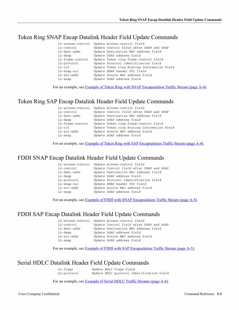
Token Ring SNAP Encap Datalink Header Field Update Commands
Token Ring SNAP Encap Datalink Header Field Update CommandsL2-access-control Update Access-control fieldL2-control Update Control field after DSAP and SSAPL2-dest-addr Update Destination MAC address fieldL2-dsap Update DSAP address fieldL2-frame-control Update Token ring frame-control fieldL2-protocol Update Protocol identification fieldL2-rif Update Token ring Routing Information FieldL2-snap-oui Update SNAP header OUI fieldL2-src-addr Update Source MAC address fieldL2-ssap Update SSAP address field
For an example, see Example of Token Ring with SNAP Encapsulation Traffic Stream (page A-4).
Token Ring SAP Encap Datalink Header Field Update CommandsL2-access-control Update Access-control fieldL2-control Update Control field after DSAP and SSAPL2-dest-addr Update Destination MAC address fieldL2-dsap Update DSAP address fieldL2-frame-control Update Token ring frame-control fieldL2-rif Update Token ring Routing Information FieldL2-src-addr Update Source MAC address fieldL2-ssap Update SSAP address field
For an example, see Example of Token Ring with SAP Encapsulation Traffic Stream (page A-4).
FDDI SNAP Encap Datalink Header Field Update CommandsL2-access-control Update Access-control fieldL2-control Update Control field after DSAP and SSAPL2-dest-addr Update Destination MAC address fieldL2-dsap Update DSAP address fieldL2-protocol Update Protocol identification fieldL2-snap-oui Update SNAP header OUI fieldL2-src-addr Update Source MAC address fieldL2-ssap Update SSAP address field
For an example, see Example of FDDI with SNAP Encapsulation Traffic Stream (page A-5).
FDDI SAP Encap Datalink Header Field Update CommandsL2-access-control Update Access-control fieldL2-control Update Control field after DSAP and SSAPL2-dest-addr Update Destination MAC address fieldL2-dsap Update DSAP address fieldL2-src-addr Update Source MAC address fieldL2-ssap Update SSAP address field
For an example, see Example of FDDI with SAP Encapsulation Traffic Stream (page A-5).
Serial HDLC Datalink Header Field Update CommandsL2-flags Update HDLC flags fieldL2-protocol Update HDLC protocol identification field
For an example, see Example of Serial HDLC Traffic Streams (page A-6).
Cisco Company Confidential Command Reference 2-3
L3-.... – Updating the Network Header Definition
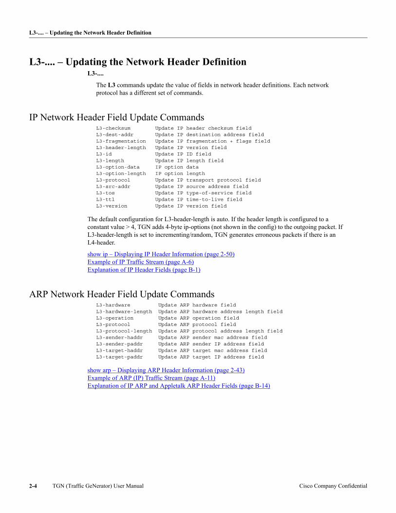
L3-.... – Updating the Network Header DefinitionL3-....
The L3 commands update the value of fields in network header definitions. Each network protocol has a different set of commands.
IP Network Header Field Update CommandsL3-checksum Update IP header checksum fieldL3-dest-addr Update IP destination address fieldL3-fragmentation Update IP fragmentation + flags fieldL3-header-length Update IP version fieldL3-id Update IP ID fieldL3-length Update IP length fieldL3-option-data IP option dataL3-option-length IP option lengthL3-protocol Update IP transport protocol fieldL3-src-addr Update IP source address fieldL3-tos Update IP type-of-service fieldL3-ttl Update IP time-to-live fieldL3-version Update IP version field
The default configuration for L3-header-length is auto. If the header length is configured to a constant value > 4, TGN adds 4-byte ip-options (not shown in the config) to the outgoing packet. If L3-header-length is set to incrementing/random, TGN generates erroneous packets if there is an L4-header.
show ip – Displaying IP Header Information (page 2-50) Example of IP Traffic Stream (page A-6) Explanation of IP Header Fields (page B-1)
ARP Network Header Field Update CommandsL3-hardware Update ARP hardware fieldL3-hardware-length Update ARP hardware address length fieldL3-operation Update ARP operation fieldL3-protocol Update ARP protocol fieldL3-protocol-length Update ARP protocol address length fieldL3-sender-haddr Update ARP sender mac address fieldL3-sender-paddr Update ARP sender IP address fieldL3-target-haddr Update ARP target mac address fieldL3-target-paddr Update ARP target IP address field
show arp – Displaying ARP Header Information (page 2-43) Example of ARP (IP) Traffic Stream (page A-11) Explanation of IP ARP and Appletalk ARP Header Fields (page B-14)
TGN (Traffic GeNerator) User Manual Cisco Company Confidential2-4
IPX Network Header Field Update Commands
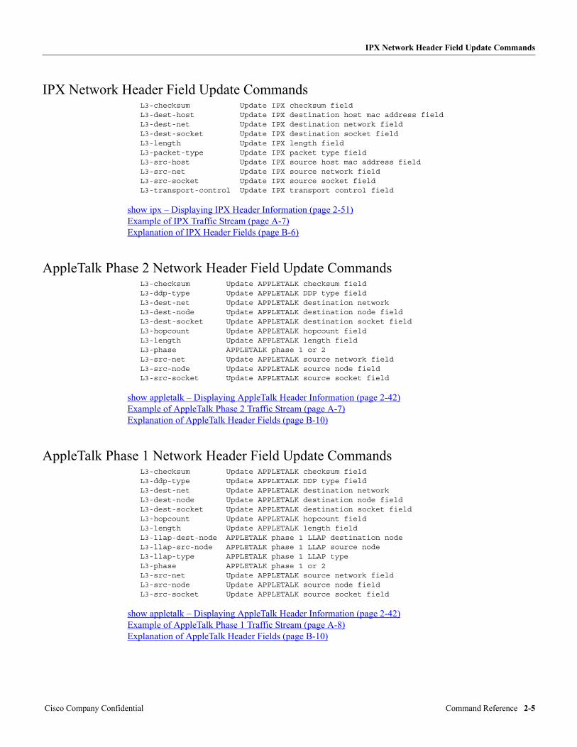
IPX Network Header Field Update CommandsL3-checksum Update IPX checksum fieldL3-dest-host Update IPX destination host mac address fieldL3-dest-net Update IPX destination network fieldL3-dest-socket Update IPX destination socket fieldL3-length Update IPX length fieldL3-packet-type Update IPX packet type fieldL3-src-host Update IPX source host mac address fieldL3-src-net Update IPX source network fieldL3-src-socket Update IPX source socket fieldL3-transport-control Update IPX transport control field
show ipx – Displaying IPX Header Information (page 2-51) Example of IPX Traffic Stream (page A-7) Explanation of IPX Header Fields (page B-6)
AppleTalk Phase 2 Network Header Field Update CommandsL3-checksum Update APPLETALK checksum fieldL3-ddp-type Update APPLETALK DDP type fieldL3-dest-net Update APPLETALK destination networkL3-dest-node Update APPLETALK destination node fieldL3-dest-socket Update APPLETALK destination socket fieldL3-hopcount Update APPLETALK hopcount fieldL3-length Update APPLETALK length fieldL3-phase APPLETALK phase 1 or 2L3-src-net Update APPLETALK source network fieldL3-src-node Update APPLETALK source node fieldL3-src-socket Update APPLETALK source socket field
show appletalk – Displaying AppleTalk Header Information (page 2-42) Example of AppleTalk Phase 2 Traffic Stream (page A-7) Explanation of AppleTalk Header Fields (page B-10)
AppleTalk Phase 1 Network Header Field Update CommandsL3-checksum Update APPLETALK checksum fieldL3-ddp-type Update APPLETALK DDP type fieldL3-dest-net Update APPLETALK destination networkL3-dest-node Update APPLETALK destination node fieldL3-dest-socket Update APPLETALK destination socket fieldL3-hopcount Update APPLETALK hopcount fieldL3-length Update APPLETALK length fieldL3-llap-dest-node APPLETALK phase 1 LLAP destination nodeL3-llap-src-node APPLETALK phase 1 LLAP source nodeL3-llap-type APPLETALK phase 1 LLAP typeL3-phase APPLETALK phase 1 or 2L3-src-net Update APPLETALK source network fieldL3-src-node Update APPLETALK source node fieldL3-src-socket Update APPLETALK source socket field
show appletalk – Displaying AppleTalk Header Information (page 2-42) Example of AppleTalk Phase 1 Traffic Stream (page A-8) Explanation of AppleTalk Header Fields (page B-10)
Cisco Company Confidential Command Reference 2-5
L3-.... – Updating the Network Header Definition
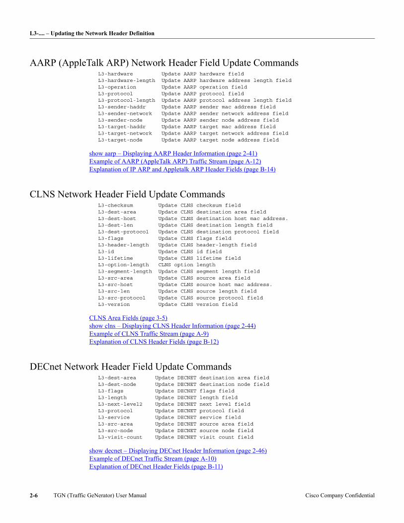
AARP (AppleTalk ARP) Network Header Field Update CommandsL3-hardware Update AARP hardware fieldL3-hardware-length Update AARP hardware address length fieldL3-operation Update AARP operation fieldL3-protocol Update AARP protocol fieldL3-protocol-length Update AARP protocol address length fieldL3-sender-haddr Update AARP sender mac address fieldL3-sender-network Update AARP sender network address fieldL3-sender-node Update AARP sender node address fieldL3-target-haddr Update AARP target mac address fieldL3-target-network Update AARP target network address fieldL3-target-node Update AARP target node address field
show aarp – Displaying AARP Header Information (page 2-41) Example of AARP (AppleTalk ARP) Traffic Stream (page A-12) Explanation of IP ARP and Appletalk ARP Header Fields (page B-14)
CLNS Network Header Field Update CommandsL3-checksum Update CLNS checksum fieldL3-dest-area Update CLNS destination area fieldL3-dest-host Update CLNS destination host mac address.L3-dest-len Update CLNS destination length fieldL3-dest-protocol Update CLNS destination protocol fieldL3-flags Update CLNS flags fieldL3-header-length Update CLNS header-length fieldL3-id Update CLNS id fieldL3-lifetime Update CLNS lifetime fieldL3-option-length CLNS option lengthL3-segment-length Update CLNS segment length fieldL3-src-area Update CLNS source area fieldL3-src-host Update CLNS source host mac address.L3-src-len Update CLNS source length fieldL3-src-protocol Update CLNS source protocol fieldL3-version Update CLNS version field
CLNS Area Fields (page 3-5) show clns – Displaying CLNS Header Information (page 2-44) Example of CLNS Traffic Stream (page A-9) Explanation of CLNS Header Fields (page B-12)
DECnet Network Header Field Update CommandsL3-dest-area Update DECNET destination area fieldL3-dest-node Update DECNET destination node fieldL3-flags Update DECNET flags fieldL3-length Update DECNET length fieldL3-next-level2 Update DECNET next level fieldL3-protocol Update DECNET protocol fieldL3-service Update DECNET service fieldL3-src-area Update DECNET source area fieldL3-src-node Update DECNET source node fieldL3-visit-count Update DECNET visit count field
show decnet – Displaying DECnet Header Information (page 2-46) Example of DECnet Traffic Stream (page A-10) Explanation of DECnet Header Fields (page B-11)
TGN (Traffic GeNerator) User Manual Cisco Company Confidential2-6
L4-.... – Updating the Transport Header Definition
L4-.... – Updating the Transport Header DefinitionL4-....
The L4 commands update the value of fields in transport header definitions. Each transport protocol has a different set of commands.
TCP Transport Header Field Update CommandsL4-acknowledge Update TCP acknowledge number fieldL4-checksum Update TCP header checksum fieldL4-dest-port Update TCP destination port fieldL4-flags Update TCP flags fieldL4-header-length Update TCP header-length fieldL4-option-data TCP option dataL4-option-length TCP option lengthL4-sequence Update TCP sequence number fieldL4-src-port Update TCP source port fieldL4-urgent Update TCP urgent pointer fieldL4-window Update TCP window field
show tcp – Displaying TCP Header Information (page 2-58) Example of TCP Traffic Stream (page A-13) Explanation of TCP Header Fields (page B-3)
UDP Transport Header Field Update CommandsL4-checksum Update UDP checksum fieldL4-dest-port Update UDP destination port fieldL4-length Update UDP length fieldL4-src-port Update UDP source port field
show udp – Displaying UDP Header Information (page 2-59) Example of UDP Traffic Stream (page A-14) Explanation of UDP Header Fields (page B-4)
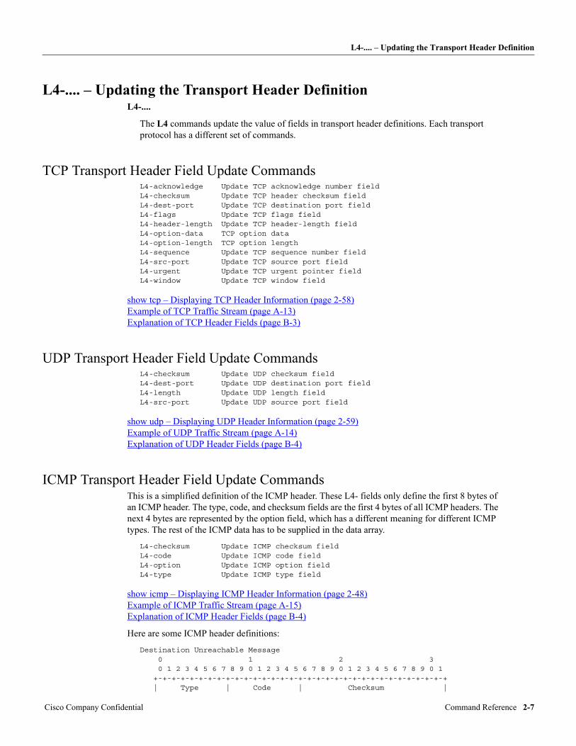
ICMP Transport Header Field Update CommandsThis is a simplified definition of the ICMP header. These L4- fields only define the first 8 bytes of an ICMP header. The type, code, and checksum fields are the first 4 bytes of all ICMP headers. The next 4 bytes are represented by the option field, which has a different meaning for different ICMP types. The rest of the ICMP data has to be supplied in the data array.
L4-checksum Update ICMP checksum fieldL4-code Update ICMP code fieldL4-option Update ICMP option fieldL4-type Update ICMP type field
show icmp – Displaying ICMP Header Information (page 2-48) Example of ICMP Traffic Stream (page A-15) Explanation of ICMP Header Fields (page B-4)
Here are some ICMP header definitions:
Destination Unreachable Message 0 1 2 3 0 1 2 3 4 5 6 7 8 9 0 1 2 3 4 5 6 7 8 9 0 1 2 3 4 5 6 7 8 9 0 1 +-+-+-+-+-+-+-+-+-+-+-+-+-+-+-+-+-+-+-+-+-+-+-+-+-+-+-+-+-+-+-+-+ | Type | Code | Checksum |
Cisco Company Confidential Command Reference 2-7
L4-.... – Updating the Transport Header Definition
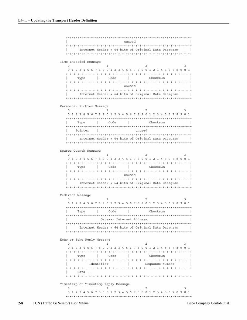
+-+-+-+-+-+-+-+-+-+-+-+-+-+-+-+-+-+-+-+-+-+-+-+-+-+-+-+-+-+-+-+-+ | unused | +-+-+-+-+-+-+-+-+-+-+-+-+-+-+-+-+-+-+-+-+-+-+-+-+-+-+-+-+-+-+-+-+ | Internet Header + 64 bits of Original Data Datagram | +-+-+-+-+-+-+-+-+-+-+-+-+-+-+-+-+-+-+-+-+-+-+-+-+-+-+-+-+-+-+-+-+
Time Exceeded Message 0 1 2 3 0 1 2 3 4 5 6 7 8 9 0 1 2 3 4 5 6 7 8 9 0 1 2 3 4 5 6 7 8 9 0 1 +-+-+-+-+-+-+-+-+-+-+-+-+-+-+-+-+-+-+-+-+-+-+-+-+-+-+-+-+-+-+-+-+ | Type | Code | Checksum | +-+-+-+-+-+-+-+-+-+-+-+-+-+-+-+-+-+-+-+-+-+-+-+-+-+-+-+-+-+-+-+-+ | unused | +-+-+-+-+-+-+-+-+-+-+-+-+-+-+-+-+-+-+-+-+-+-+-+-+-+-+-+-+-+-+-+-+ | Internet Header + 64 bits of Original Data Datagram | +-+-+-+-+-+-+-+-+-+-+-+-+-+-+-+-+-+-+-+-+-+-+-+-+-+-+-+-+-+-+-+-+
Parameter Problem Message 0 1 2 3 0 1 2 3 4 5 6 7 8 9 0 1 2 3 4 5 6 7 8 9 0 1 2 3 4 5 6 7 8 9 0 1 +-+-+-+-+-+-+-+-+-+-+-+-+-+-+-+-+-+-+-+-+-+-+-+-+-+-+-+-+-+-+-+-+ | Type | Code | Checksum | +-+-+-+-+-+-+-+-+-+-+-+-+-+-+-+-+-+-+-+-+-+-+-+-+-+-+-+-+-+-+-+-+ | Pointer | unused | +-+-+-+-+-+-+-+-+-+-+-+-+-+-+-+-+-+-+-+-+-+-+-+-+-+-+-+-+-+-+-+-+ | Internet Header + 64 bits of Original Data Datagram | +-+-+-+-+-+-+-+-+-+-+-+-+-+-+-+-+-+-+-+-+-+-+-+-+-+-+-+-+-+-+-+-+
Source Quench Message 0 1 2 3 0 1 2 3 4 5 6 7 8 9 0 1 2 3 4 5 6 7 8 9 0 1 2 3 4 5 6 7 8 9 0 1 +-+-+-+-+-+-+-+-+-+-+-+-+-+-+-+-+-+-+-+-+-+-+-+-+-+-+-+-+-+-+-+-+ | Type | Code | Checksum | +-+-+-+-+-+-+-+-+-+-+-+-+-+-+-+-+-+-+-+-+-+-+-+-+-+-+-+-+-+-+-+-+ | unused | +-+-+-+-+-+-+-+-+-+-+-+-+-+-+-+-+-+-+-+-+-+-+-+-+-+-+-+-+-+-+-+-+ | Internet Header + 64 bits of Original Data Datagram | +-+-+-+-+-+-+-+-+-+-+-+-+-+-+-+-+-+-+-+-+-+-+-+-+-+-+-+-+-+-+-+-+
Redirect Message 0 1 2 3 0 1 2 3 4 5 6 7 8 9 0 1 2 3 4 5 6 7 8 9 0 1 2 3 4 5 6 7 8 9 0 1 +-+-+-+-+-+-+-+-+-+-+-+-+-+-+-+-+-+-+-+-+-+-+-+-+-+-+-+-+-+-+-+-+ | Type | Code | Checksum | +-+-+-+-+-+-+-+-+-+-+-+-+-+-+-+-+-+-+-+-+-+-+-+-+-+-+-+-+-+-+-+-+ | Gateway Internet Address | +-+-+-+-+-+-+-+-+-+-+-+-+-+-+-+-+-+-+-+-+-+-+-+-+-+-+-+-+-+-+-+-+ | Internet Header + 64 bits of Original Data Datagram | +-+-+-+-+-+-+-+-+-+-+-+-+-+-+-+-+-+-+-+-+-+-+-+-+-+-+-+-+-+-+-+-+
Echo or Echo Reply Message 0 1 2 3 0 1 2 3 4 5 6 7 8 9 0 1 2 3 4 5 6 7 8 9 0 1 2 3 4 5 6 7 8 9 0 1 +-+-+-+-+-+-+-+-+-+-+-+-+-+-+-+-+-+-+-+-+-+-+-+-+-+-+-+-+-+-+-+-+ | Type | Code | Checksum | +-+-+-+-+-+-+-+-+-+-+-+-+-+-+-+-+-+-+-+-+-+-+-+-+-+-+-+-+-+-+-+-+ | Identifier | Sequence Number | +-+-+-+-+-+-+-+-+-+-+-+-+-+-+-+-+-+-+-+-+-+-+-+-+-+-+-+-+-+-+-+-+ | Data ... +-+-+-+-+-+-+-+-+-+-+-+-+-+-+-+-+-+-+-+-+-+-+-+-+-+-+-+-+-+-+-+-+
Timestamp or Timestamp Reply Message 0 1 2 3 0 1 2 3 4 5 6 7 8 9 0 1 2 3 4 5 6 7 8 9 0 1 2 3 4 5 6 7 8 9 0 1 +-+-+-+-+-+-+-+-+-+-+-+-+-+-+-+-+-+-+-+-+-+-+-+-+-+-+-+-+-+-+-+-+
TGN (Traffic GeNerator) User Manual Cisco Company Confidential2-8
IGMP Transport Header Field Update Commands
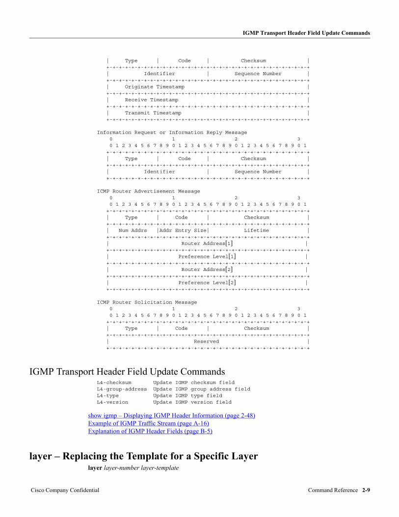
| Type | Code | Checksum | +-+-+-+-+-+-+-+-+-+-+-+-+-+-+-+-+-+-+-+-+-+-+-+-+-+-+-+-+-+-+-+-+ | Identifier | Sequence Number | +-+-+-+-+-+-+-+-+-+-+-+-+-+-+-+-+-+-+-+-+-+-+-+-+-+-+-+-+-+-+-+-+ | Originate Timestamp | +-+-+-+-+-+-+-+-+-+-+-+-+-+-+-+-+-+-+-+-+-+-+-+-+-+-+-+-+-+-+-+-+ | Receive Timestamp | +-+-+-+-+-+-+-+-+-+-+-+-+-+-+-+-+-+-+-+-+-+-+-+-+-+-+-+-+-+-+-+-+ | Transmit Timestamp | +-+-+-+-+-+-+-+-+-+-+-+-+-+-+-+-+-+-+-+-+-+-+-+-+-+-+-+-+-+-+-+-+
Information Request or Information Reply Message 0 1 2 3 0 1 2 3 4 5 6 7 8 9 0 1 2 3 4 5 6 7 8 9 0 1 2 3 4 5 6 7 8 9 0 1 +-+-+-+-+-+-+-+-+-+-+-+-+-+-+-+-+-+-+-+-+-+-+-+-+-+-+-+-+-+-+-+-+ | Type | Code | Checksum | +-+-+-+-+-+-+-+-+-+-+-+-+-+-+-+-+-+-+-+-+-+-+-+-+-+-+-+-+-+-+-+-+ | Identifier | Sequence Number | +-+-+-+-+-+-+-+-+-+-+-+-+-+-+-+-+-+-+-+-+-+-+-+-+-+-+-+-+-+-+-+-+
ICMP Router Advertisement Message 0 1 2 3 0 1 2 3 4 5 6 7 8 9 0 1 2 3 4 5 6 7 8 9 0 1 2 3 4 5 6 7 8 9 0 1 +-+-+-+-+-+-+-+-+-+-+-+-+-+-+-+-+-+-+-+-+-+-+-+-+-+-+-+-+-+-+-+-+ | Type | Code | Checksum | +-+-+-+-+-+-+-+-+-+-+-+-+-+-+-+-+-+-+-+-+-+-+-+-+-+-+-+-+-+-+-+-+ | Num Addrs |Addr Entry Size| Lifetime | +-+-+-+-+-+-+-+-+-+-+-+-+-+-+-+-+-+-+-+-+-+-+-+-+-+-+-+-+-+-+-+-+ | Router Address[1] | +-+-+-+-+-+-+-+-+-+-+-+-+-+-+-+-+-+-+-+-+-+-+-+-+-+-+-+-+-+-+-+-+ | Preference Level[1] | +-+-+-+-+-+-+-+-+-+-+-+-+-+-+-+-+-+-+-+-+-+-+-+-+-+-+-+-+-+-+-+-+ | Router Address[2] | +-+-+-+-+-+-+-+-+-+-+-+-+-+-+-+-+-+-+-+-+-+-+-+-+-+-+-+-+-+-+-+-+ | Preference Level[2] | +-+-+-+-+-+-+-+-+-+-+-+-+-+-+-+-+-+-+-+-+-+-+-+-+-+-+-+-+-+-+-+-+
ICMP Router Solicitation Message 0 1 2 3 0 1 2 3 4 5 6 7 8 9 0 1 2 3 4 5 6 7 8 9 0 1 2 3 4 5 6 7 8 9 0 1 +-+-+-+-+-+-+-+-+-+-+-+-+-+-+-+-+-+-+-+-+-+-+-+-+-+-+-+-+-+-+-+-+ | Type | Code | Checksum | +-+-+-+-+-+-+-+-+-+-+-+-+-+-+-+-+-+-+-+-+-+-+-+-+-+-+-+-+-+-+-+-+ | Reserved | +-+-+-+-+-+-+-+-+-+-+-+-+-+-+-+-+-+-+-+-+-+-+-+-+-+-+-+-+-+-+-+-+
IGMP Transport Header Field Update CommandsL4-checksum Update IGMP checksum fieldL4-group-address Update IGMP group address fieldL4-type Update IGMP type fieldL4-version Update IGMP version field
show igmp – Displaying IGMP Header Information (page 2-48) Example of IGMP Traffic Stream (page A-16) Explanation of IGMP Header Fields (page B-5)
layer – Replacing the Template for a Specific Layerlayer layer-number layer-template
Cisco Company Confidential Command Reference 2-9
add – Adding a Traffic Stream
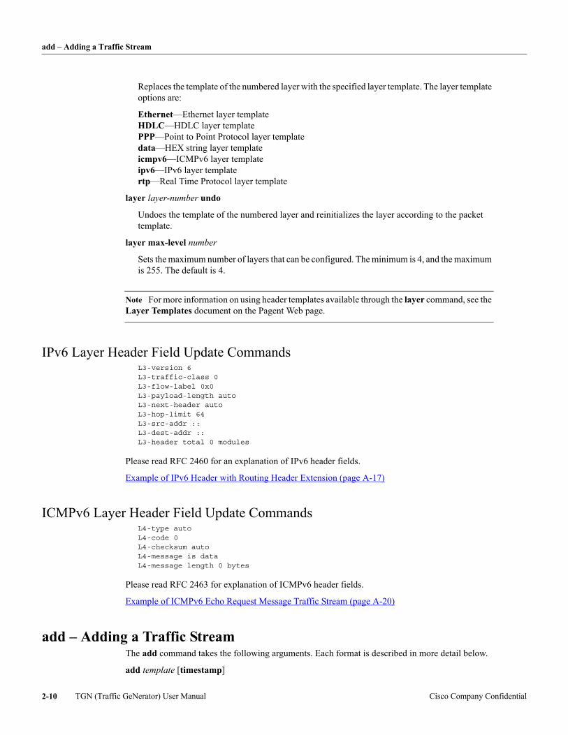
Replaces the template of the numbered layer with the specified layer template. The layer template options are:
Ethernet—Ethernet layer template HDLC—HDLC layer template PPP—Point to Point Protocol layer template data—HEX string layer template icmpv6—ICMPv6 layer template ipv6—IPv6 layer template rtp—Real Time Protocol layer template
layer layer-number undo
Undoes the template of the numbered layer and reinitializes the layer according to the packet template.
layer max-level number
Sets the maximum number of layers that can be configured. The minimum is 4, and the maximum is 255. The default is 4.
Note For more information on using header templates available through the layer command, see the Layer Templates document on the Pagent Web page.
IPv6 Layer Header Field Update CommandsL3-version 6L3-traffic-class 0L3-flow-label 0x0L3-payload-length autoL3-next-header autoL3-hop-limit 64L3-src-addr ::L3-dest-addr ::L3-header total 0 modules
Please read RFC 2460 for an explanation of IPv6 header fields.
Example of IPv6 Header with Routing Header Extension (page A-17)
ICMPv6 Layer Header Field Update CommandsL4-type autoL4-code 0L4-checksum autoL4-message is dataL4-message length 0 bytes
Please read RFC 2463 for explanation of ICMPv6 header fields.
Example of ICMPv6 Echo Request Message Traffic Stream (page A-20)
add – Adding a Traffic StreamThe add command takes the following arguments. Each format is described in more detail below.
add template [timestamp]
TGN (Traffic GeNerator) User Manual Cisco Company Confidential2-10
add – Adding a Traffic Stream
Creates a traffic stream based on a template.
add pkts-packet [pkt# [to to-pkt#]] [filter-with {active-display-filters | pkts-filter-name}] [tag] [timestamp]
Creates a traffic stream based on a packet in a PKTS capture buffer.
add interface ts-name-or-number
Creates a traffic stream by cloning an existing traffic stream.
add mixed-interface [primary | secondary slot-number] ts-name-or-number
Creates a traffic stream by cloning an existing traffic stream from a mixed interface.
add {arp | aarp} responder
Creates an IP or AppleTalk ARP responder.
add {decnet | clns} hello-generator
Creates a DECnet or Connectionless Network Service (CLNS) hello-generator.
add sniffer-file url
Creates a traffic stream based on sniffer file.
add flow
Creates a traffic stream containing a packet flow.
add sequence
Creates a traffic stream containing a sequence of packets.
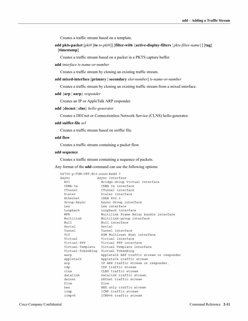
Any format of the add command can use the following options:
k4700-p(TGN:OFF,Et0:none)#add ?Async Async interface BVI Bridge-Group Virtual Interface CDMA-Ix CDMA Ix interface CTunnel CTunnel interface Dialer Dialer interface Ethernet IEEE 802.3 Group-Async Async Group interface Lex Lex interface Loopback Loopback interface MFR Multilink Frame Relay bundle interface Multilink Multilink-group interface Null Null interface Serial Serial Tunnel Tunnel interface Vif PGM Multicast Host interface Virtual Virtual interface Virtual-PPP Virtual PPP interface Virtual-Template Virtual Template interface Virtual-TokenRing Virtual TokenRing aarp Appletalk ARP traffic stream or responder appletalk Appletalk traffic stream arp IP ARP traffic stream or responder. cdp CDP traffic stream clns CLNS traffic stream datalink Datalink traffic stream. decnet DECnet traffic stream flow flow hex HEX only traffic stream icmp ICMP traffic stream icmpv6 ICMPv6 traffic stream
Cisco Company Confidential Command Reference 2-11
add – Adding a Traffic Stream
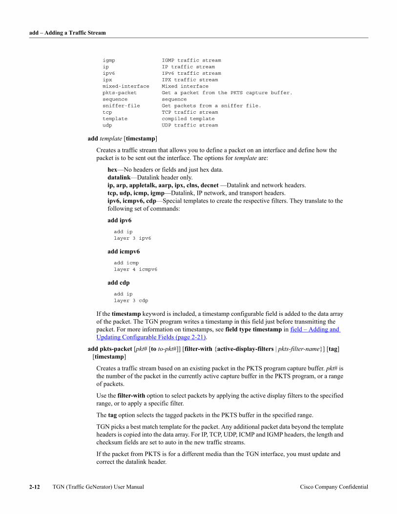
igmp IGMP traffic stream ip IP traffic stream ipv6 IPv6 traffic stream ipx IPX traffic stream mixed-interface Mixed interface pkts-packet Get a packet from the PKTS capture buffer. sequence sequence sniffer-file Get packets from a sniffer file. tcp TCP traffic stream template compiled template udp UDP traffic stream
add template [timestamp]
Creates a traffic stream that allows you to define a packet on an interface and define how the packet is to be sent out the interface. The options for template are:
hex—No headers or fields and just hex data. datalink—Datalink header only. ip, arp, appletalk, aarp, ipx, clns, decnet —Datalink and network headers. tcp, udp, icmp, igmp—Datalink, IP network, and transport headers. ipv6, icmpv6, cdp—Special templates to create the respective filters. They translate to the following set of commands:
add ipv6
add iplayer 3 ipv6
add icmpv6
add icmplayer 4 icmpv6
add cdp
add iplayer 3 cdp
If the timestamp keyword is included, a timestamp configurable field is added to the data array of the packet. The TGN program writes a timestamp in this field just before transmitting the packet. For more information on timestamps, see field type timestamp in field – Adding and Updating Configurable Fields (page 2-21).
add pkts-packet [pkt# [to to-pkt#]] [filter-with {active-display-filters | pkts-filter-name}] [tag] [timestamp]
Creates a traffic stream based on an existing packet in the PKTS program capture buffer. pkt# is the number of the packet in the currently active capture buffer in the PKTS program, or a range of packets.
Use the filter-with option to select packets by applying the active display filters to the specified range, or to apply a specific filter.
The tag option selects the tagged packets in the PKTS buffer in the specified range.
TGN picks a best match template for the packet. Any additional packet data beyond the template headers is copied into the data array. For IP, TCP, UDP, ICMP and IGMP headers, the length and checksum fields are set to auto in the new traffic streams.
If the packet from PKTS is for a different media than the TGN interface, you must update and correct the datalink header.
TGN (Traffic GeNerator) User Manual Cisco Company Confidential2-12
all – Updating Multiple Traffic Streams
When a packet is captured with subinterface (ios-dependent) capture, PKTS does not know the L2-header for the packet. Hence, it is not copied into the traffic stream.
If the timestamp keyword is included, a timestamp configurable field is added to the data array of the packet. The TGN program writes a timestamp in this field just before transmitting the packet. For more information on timestamps, see field type timestamp in field – Adding and Updating Configurable Fields (page 2-21).
add interface ts-name-or-number
Creates a traffic steam by cloning an existing traffic stream. The traffic stream to be cloned is identified by the interface it is configured on and its name or number.
If the cloned interfaces are on different media than the original, the datalink header cannot be duplicated, and you must define the datalink fields in the cloned traffic stream (see L2-.... – Updating the Datalink Header Definition (page 2-1)).
add mixed-interface [primary | secondary slot-number] ts-name-or-number
Creates a traffic stream by cloning an existing traffic stream from a mixed interface.
add {arp | aarp} responder
Creates a process that responds to ARP requests for a specific IP or AppleTalk address with an ARP response. This allows a router under test to fill its ARP cache, so it can forward a packet onto a local network.
add {decnet | clns} hello-generator
Creates a process that sends end-node hello packets every 30 seconds to simulate an active station for the DECnet and CLNS protocols. A router needs to receive end-node hellos for these protocols, so it knows which interface a station is on and the station’s MAC address.
add sniffer-file url
Adds a batch of traffic streams from an .ENC sniffer file or a .pcap/.cap libpcap file or a .cap netxray file to the currently selected interface, regardless of the media type. The file is read in using the IOS File System (IFS). The use of url is similar to loading a configuration from IFS (see load-config – Loading a Configuration from IFS (page 2-29)).
add sequence
Creates a traffic stream containing a sequence of packets. Each packet in the sequence is defined with a separate traffic stream. The sequence is defined with a list of references to traffic streams with packet definitions (see sequence – Adding and Updating Packet Sequences (page 2-38)).
add flow
Creates a traffic stream containing a sequence of packets. Each packet (member) in the flow is defined with a separate traffic stream (see flow – Adding and Updating Packet Flows (page 2-25)).
clear – Clearing Configurations or Counters (page 2-16) delete – Deleting One or Several Traffic Streams (page 2-19) expand – Expanding a Traffic Stream into Multiple Copies (page 2-20) insert-at – Inserting a Traffic Stream (page 2-27)
all – Updating Multiple Traffic Streamsall [template] [from ts-name-or-number [to ts-name-or-number]]
Cisco Company Confidential Command Reference 2-13
all – Updating Multiple Traffic Streams
Preceding a command that updates a traffic stream configuration with the keyword all causes the command to be applied to all traffic streams.
In non-broadcast mode, the command is applied to all TGN traffic streams on the selected interface.
In broadcast mode, all is implied, and the command is applied to all TGN traffic streams on all interfaces (see bit-rate - Setting the transmission Rate in bits per second (page 2-15)). For how broadcast mode works on flow traffic streams, see Effect of Broadcast Mode and all Commands on Flow Traffic Streams (page 2-15).
In both cases, commands that update header field definitions only apply to traffic streams of the same template as the currently selected traffic stream. For example, if the currently selected traffic stream is a TCP template, the command updates TCP traffic streams only.
template
Limits the command to only traffic streams of a specific template. Valid templates are:
datalink ip arp arp responder tcp udp icmp igmp appletalk aarp aarp responder ipx decnet decnet hello-generator clns clns hello-generator
from ts-name-or-number [to ts-name-or-number]
Limits the command to a specific range of traffic streams. You can identify the traffic streams by name or number. If identifying by name, you must enter the full exact name.
If you are in broadcast mode, both traffic stream names must refer to traffic streams on the same interface. The command is applied to the selected range on all interfaces.
If in non-broadcast mode, traffic stream names must be on the currently selected interface.
Examples
all length 1000
Sets all traffic streams to send packets of 1000 byte length.
all ip L3-dest-addr 100.1.1.1
Sets all traffic streams with an ip template (note that this excludes tcp, udp, icmp, and igmp templates) to have a destination IP address of 100.1.1.1.
all from 5 to 10 rate 3000
Sets all traffic streams from number 5 to 10 to send packets at 3000 packets per second (pps).
all tcp from 10 L4-dest-port 68
TGN (Traffic GeNerator) User Manual Cisco Company Confidential2-14
bit-rate - Setting the transmission Rate in bits per second
Sets all traffic streams with a tcp template, starting with number 10 to the last traffic stream on the interface, to have a TCP destination port address of 68.
bit-rate - Setting the transmission Rate in bits per secondbit-rate bits-per-second
Sets the traffic transmission rate. This command is useful when high precision is required.
ordered-traffic – Setting Ordered-Traffic Scheduling (page 2-32)
rate – Setting the Packet Send Rate (page 2-35)
interval – Setting the Interval Between Sending Packets (page 2-27)
variability – Defining the Variability in Packet Intervals (page 2-60)
show rate – Displaying Traffic Stream Rates (page 2-55)
broadcast – Broadcast Modebroadcast [on | off]
The broadcast command puts the TGN program in broadcast mode. This mode is reflected in the command prompts in that the selected interface and traffic stream number are replaced by the word “Broadcast.” Broadcast mode allows all traffic streams (or a subset with the all modifier) on all interfaces to be reviewed and updated.
In broadcast mode, the all command is implicit, since the purpose of the mode is to affect all traffic streams, but you have to include the all keyword to use the “template” or “traffic stream range” options (see all – Updating Multiple Traffic Streams (page 2-13)).
In broadcast mode, commands that update header field definitions only apply to traffic streams of the same template as the currently selected traffic stream. For example, if the currently selected traffic stream is a TCP template, the command updates TCP traffic streams only.
You can use either broadcast or broadcast on to go to broadcast mode, and tgn or broadcast off to turn broadcast mode off.
Effect of Broadcast Mode and all Commands on Flow Traffic StreamsThe following occurs when you are in flow mode and using broadcast mode and the all commands:
• If a flow traffic stream matches the specified criteria, the broadcast mode commands and all commands that are applicable to flow traffic streams (delayed-start, rate, interval, off, and on commands) update the flow traffic stream but do not affect its members.
• If a flow traffic stream matches the specified criteria, the broadcast mode commands and all commands that are not applicable to flow traffic streams but are applicable to flow members (that is, the send command), do not affect the flow traffic stream but update all its members.
• If a flow traffic stream matches the specified criteria, the broadcast mode commands and all commands that update header field definitions update all its members.
For example, if 4 is a flow traffic stream, all the following commands update all members of flow traffic stream 4:
Cisco Company Confidential Command Reference 2-15
burst – Sending Traffic Stream in Bursts
k4700-p(TGN:OFF,Et0:2/8)#all from 2 to 6 send 8k4700-p(TGN:OFF,Et0:2/8)#all from 2 to 6 L3-des 2.3.4.5k4700-p(TGN:OFF,Et0:2/8)#br onk4700-p(TGN:OFF,Broadcast)#all from 2 to 6 L3-des 2.3.4.5k4700-p(TGN:OFF,Broadcast)#all from 2 to 6 send 8
In the following example, the off, on, and delayed-start commands (which are all commands and broadcast mode commands) update flow traffic stream 4, but not its members. However, the repeat command does not affect the flow or the flow members, because the command is not available for flow traffic streams or flow members. The last command in the example updates all members of the flow with tcp templates.
k4700-p(TGN:OFF,Et0:2/8)#all from 2 to 6 offk4700-p(TGN:OFF,Et0:2/8)#all from 2 to 6 delayed-start 4k4700-p(TGN:OFF,Et0:2/8)#br onk4700-p(TGN:OFF,Broadcast)#all from 2 to 6 onk4700-p(TGN:OFF,Broadcast)#all from 2 to 6 delayed-start 4k4700-p(TGN:OFF,Broadcast)#all from 2 to 6 repeat 4k4700-p(TGN:OFF,Et0:2/8)#br onk4700-p(TGN:OFF,Et0:2/8)#all from 2 to 6 repeat 4k4700-p(TGN:OFF,Et0:2/8)#all tcp from 2 to 6 send 20
burst – Sending Traffic Stream in Burstsburst {on | off} burst duration on n1 [to n2] burst duration off n1 [to n2]
TGN can send a traffic stream continuously or in bursts. With the command burst off, the traffic stream is sent continuously. The command burst on causes the traffic stream to be sent in bursts.
The burst duration on and burst duration off commands determine how long, in milliseconds, the burst will be on and off. If only n1 is specified, the burst is on or off for the specified amount of time. If n1 and n2 are entered (n2 must be greater than n1), the duration is random within the time range specified by n1 and n2.
For example:
rate 1000burst onburst duration on 1000 to 10000burst duration off 5000 to 10000
This combination of commands causes the traffic stream to send packets at 1000 pps for one second, wait for 5 to 10 seconds, send packets for one second, wait for 5 to 10 seconds, and so on.
show burst – Displaying Burst Configurations (page 2-44)
clear – Clearing Configurations or Countersclear {all | config | count}
These commands clear configurations, counters, or log files. They affect all traffic streams in both flow and non-flow mode, including all flow members.
clear all clear config
Both of these two commands delete all TGN traffic streams configured on all interfaces.
delete – Deleting One or Several Traffic Streams (page 2-19)
TGN (Traffic GeNerator) User Manual Cisco Company Confidential2-16
close-logfile – Closing an Open IFS Log File
clear count
Traffic streams keep a count of the number of packets they have sent. This sets the send count for all traffic streams to zero.
close-logfile – Closing an Open IFS Log Fileclose-logfile
Closes an IFS log file that was opened with the open-logfile command.
IOS File System (page 1-10) open-logfile – Opening an IFS Log File (page 2-31) write – Writing Information to an IFS Log File (page 2-61)
data – Setting Data in a Data Arraydata starting-byte-offset “hex-data-string”
Creates and updates a traffic stream data array. The default is that a data array does not appear when the traffic stream configuration is displayed.
starting-byte-offset
Specifies where the data being defined starts in the data array.
“hex-data-string”
Specifies the string of hex numbers to put into the data array.
For example, to create a data array and put data into it:
data 24 "24 11"
This example creates a data array 26 bytes long, writes the hex number 24 into location 24, and the hex number 11 into location 25. Since this is creating the array, the locations from 0 to 23 are set to zero.
If the example was updating an existing data array of at least 26 bytes length, only locations 24 and 25 would be updated.
If we display the traffic stream configuration, we will see the following:
!data-length 26! 0 1 2 3 4 5 6 7 8 9 10 11 12 13 14 15 16 17 18 19data 0 "00 00 00 00 00 00 00 00 00 00 00 00 00 00 00 00 00 00 00 00"data 20 "00 00 00 00 24 11"!
data-length – Setting the Data Array Length (page 2-17)
data-length – Setting the Data Array Lengthdata-length length
Sets how much of the data array to use when a packet is created. length is the data array length in bytes. If length is set to less than the data in the data array, only that reduced portion of the data array is used. If it is set to greater than the data array, the size of the data array is increased and padded with zeros.
Cisco Company Confidential Command Reference 2-17
datalink – Specifying the Datalink Header Encapsulation
If the data command is used to add data to the data array and it increases the size of the array, data-length is updated to the new data array size.
data – Setting Data in a Data Array (page 2-17)
datalink – Specifying the Datalink Header Encapsulationdatalink user-defined [hex] datalink ios-dependent [subinterface-name]
Specifies how the datalink header is assembled. By default, it is assembled with user-defined header field values.
The hex option configures the datalink header as a hex string, which can be configured using the commands L2-data and L2-data-length. This allows a packet with any datalink header to be transmitted over an interface (see Example of Unknown Datalink Header with IP and TCP Headers (page A-1)).
For a subset of built-in packet templates (currently only IP-based protocol header templates), the datalink command provides an additional option of assembling the datalink header through the Cisco IOS media stack.
When a traffic stream is configured with the ios-dependent option in combination with a subinterface name, the datalink protocol header is encapsulated according to the subinterface configuration on the router. This makes media without built-in protocol header templates and/or subinterfaces more compatible with the application.
This feature is not supported on distributed CPUs.
L2-.... – Updating the Datalink Header Definition (page 2-1) Defining and Sending TGN Packets on a Subinterface (page 1-5) IOS-Dependent Datalink Header Update Commands (page 2-2)
delayed-start – Delaying Start of Packet Generationdelayed-start {random | n {milliseconds | microseconds | nanoseconds}}
Defines how long a traffic stream waits after a start command before sending its first packet. This command is per traffic stream.
delayed-start random
Sets the delay to be a random value within the traffic stream packet interval (this is the default mode). For example, if the packet rate is 10 pps, packet interval is 100 milliseconds, and the start delay is random from 0 to 100 milliseconds.
This assumes TGN is used as a network exerciser, and the traffic streams are not starting all at once.
delayed-start n {milliseconds | microseconds | nanoseconds}
Allows the tester to define the delay. The delay can be defined in milliseconds, microseconds, or nanoseconds, whichever is most convenient. For backward compatibility with previous releases, milliseconds is assumed if the time interval is left off.
TGN uses an IOS clock that has .23 nanosecond resolution, but the real limitation here is in the time it take the software to read the clock. Following are times between back-to-back reads of the clock on specific platforms.
First read
TGN (Traffic GeNerator) User Manual Cisco Company Confidential2-18
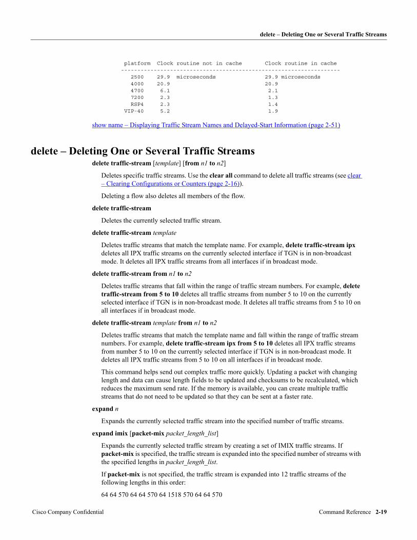
delete – Deleting One or Several Traffic Streams
platform Clock routine not in cache Clock routine in cache ------------------------------------------------------------------- 2500 29.9 microseconds 29.9 microseconds 4000 20.9 20.9 4700 6.1 2.1 7200 2.3 1.3 RSP4 2.3 1.4 VIP-40 5.2 1.9
show name – Displaying Traffic Stream Names and Delayed-Start Information (page 2-51)
delete – Deleting One or Several Traffic Streamsdelete traffic-stream [template] [from n1 to n2]
Deletes specific traffic streams. Use the clear all command to delete all traffic streams (see clear – Clearing Configurations or Counters (page 2-16)).
Deleting a flow also deletes all members of the flow.
delete traffic-stream
Deletes the currently selected traffic stream.
delete traffic-stream template
Deletes traffic streams that match the template name. For example, delete traffic-stream ipx deletes all IPX traffic streams on the currently selected interface if TGN is in non-broadcast mode. It deletes all IPX traffic streams from all interfaces if in broadcast mode.
delete traffic-stream from n1 to n2
Deletes traffic streams that fall within the range of traffic stream numbers. For example, delete traffic-stream from 5 to 10 deletes all traffic streams from number 5 to 10 on the currently selected interface if TGN is in non-broadcast mode. It deletes all traffic streams from 5 to 10 on all interfaces if in broadcast mode.
delete traffic-stream template from n1 to n2
Deletes traffic streams that match the template name and fall within the range of traffic stream numbers. For example, delete traffic-stream ipx from 5 to 10 deletes all IPX traffic streams from number 5 to 10 on the currently selected interface if TGN is in non-broadcast mode. It deletes all IPX traffic streams from 5 to 10 on all interfaces if in broadcast mode.
This command helps send out complex traffic more quickly. Updating a packet with changing length and data can cause length fields to be updated and checksums to be recalculated, which reduces the maximum send rate. If the memory is available, you can create multiple traffic streams that do not need to be updated so that they can be sent at a faster rate.
expand n
Expands the currently selected traffic stream into the specified number of traffic streams.
expand imix [packet-mix packet_length_list]
Expands the currently selected traffic stream by creating a set of IMIX traffic streams. If packet-mix is specified, the traffic stream is expanded into the specified number of streams with the specified lengths in packet_length_list.
If packet-mix is not specified, the traffic stream is expanded into 12 traffic streams of the following lengths in this order:
64 64 570 64 64 570 64 1518 570 64 64 570
Cisco Company Confidential Command Reference 2-19
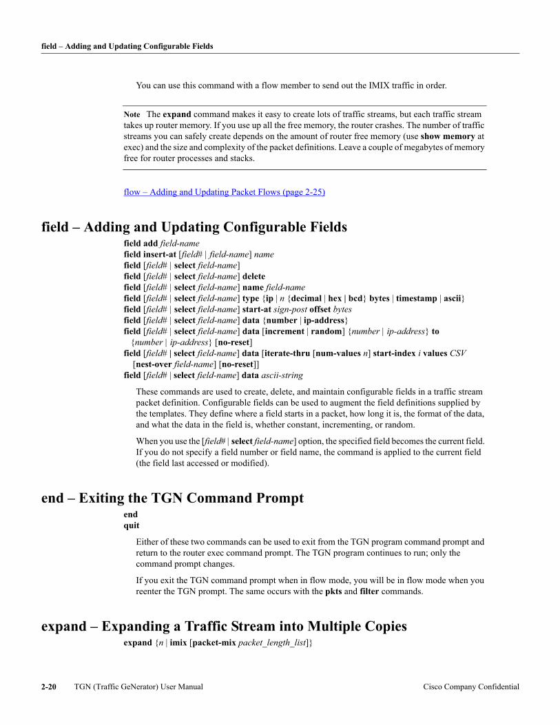
field – Adding and Updating Configurable Fields
You can use this command with a flow member to send out the IMIX traffic in order.
Note The expand command makes it easy to create lots of traffic streams, but each traffic stream takes up router memory. If you use up all the free memory, the router crashes. The number of traffic streams you can safely create depends on the amount of router free memory (use show memory at exec) and the size and complexity of the packet definitions. Leave a couple of megabytes of memory free for router processes and stacks.
flow – Adding and Updating Packet Flows (page 2-25)
field – Adding and Updating Configurable Fieldsfield add field-name field insert-at [field# | field-name] name field [field# | select field-name] field [field# | select field-name] delete field [field# | select field-name] name field-name field [field# | select field-name] type {ip | n {decimal | hex | bcd} bytes | timestamp | ascii} field [field# | select field-name] start-at sign-post offset bytes field [field# | select field-name] data {number | ip-address} field [field# | select field-name] data [increment | random] {number | ip-address} to {number | ip-address} [no-reset] field [field# | select field-name] data [iterate-thru [num-values n] start-index i values CSV [nest-over field-name] [no-reset]] field [field# | select field-name] data ascii-string
These commands are used to create, delete, and maintain configurable fields in a traffic stream packet definition. Configurable fields can be used to augment the field definitions supplied by the templates. They define where a field starts in a packet, how long it is, the format of the data, and what the data in the field is, whether constant, incrementing, or random.
When you use the [field# | select field-name] option, the specified field becomes the current field. If you do not specify a field number or field name, the command is applied to the current field (the field last accessed or modified).
end – Exiting the TGN Command Promptend quit
Either of these two commands can be used to exit from the TGN program command prompt and return to the router exec command prompt. The TGN program continues to run; only the command prompt changes.
If you exit the TGN command prompt when in flow mode, you will be in flow mode when you reenter the TGN prompt. The same occurs with the pkts and filter commands.
expand – Expanding a Traffic Stream into Multiple Copiesexpand {n | imix [packet-mix packet_length_list]}
TGN (Traffic GeNerator) User Manual Cisco Company Confidential2-20
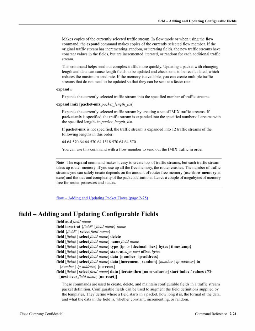
field – Adding and Updating Configurable Fields
Makes copies of the currently selected traffic stream. In flow mode or when using the flow command, the expand command makes copies of the currently selected flow member. If the original traffic stream has incrementing, random, or iterating fields, the new traffic streams have constant values in the fields, but are incremented, iterated, or random for each additional traffic stream.
This command helps send out complex traffic more quickly. Updating a packet with changing length and data can cause length fields to be updated and checksums to be recalculated, which reduces the maximum send rate. If the memory is available, you can create multiple traffic streams that do not need to be updated so that they can be sent at a faster rate.
expand n
Expands the currently selected traffic stream into the specified number of traffic streams.
expand imix [packet-mix packet_length_list]
Expands the currently selected traffic stream by creating a set of IMIX traffic streams. If packet-mix is specified, the traffic stream is expanded into the specified number of streams with the specified lengths in packet_length_list.
If packet-mix is not specified, the traffic stream is expanded into 12 traffic streams of the following lengths in this order:
64 64 570 64 64 570 64 1518 570 64 64 570
You can use this command with a flow member to send out the IMIX traffic in order.
Note The expand command makes it easy to create lots of traffic streams, but each traffic stream takes up router memory. If you use up all the free memory, the router crashes. The number of traffic streams you can safely create depends on the amount of router free memory (use show memory at exec) and the size and complexity of the packet definitions. Leave a couple of megabytes of memory free for router processes and stacks.
flow – Adding and Updating Packet Flows (page 2-25)
field – Adding and Updating Configurable Fieldsfield add field-name field insert-at {field# | field-name} name field {field# | select field-name} field [field# | select field-name] delete field [field# | select field-name] name field-name field [field# | select field-name] type {ip | n {decimal | hex} bytes | timestamp} field [field# | select field-name] start-at sign-post offset bytes field [field# | select field-name] data {number | ip-address} field [field# | select field-name] data [increment | random] {number | ip-address} to {number | ip-address} [no-reset] field [field# | select field-name] data [iterate-thru [num-values n] start-index i values CSV [nest-over field-name] [no-reset]]
These commands are used to create, delete, and maintain configurable fields in a traffic stream packet definition. Configurable fields can be used to augment the field definitions supplied by the templates. They define where a field starts in a packet, how long it is, the format of the data, and what the data in the field is, whether constant, incrementing, or random.
Cisco Company Confidential Command Reference 2-21
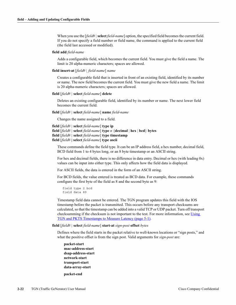
field – Adding and Updating Configurable Fields
When you use the [field# | select field-name] option, the specified field becomes the current field. If you do not specify a field number or field name, the command is applied to the current field (the field last accessed or modified).
field add field-name
Adds a configurable field, which becomes the current field. You must give the field a name. The limit is 20 alpha-numeric characters; spaces are allowed.
field insert-at [field# | field-name] name
Creates a configurable field that is inserted in front of an existing field, identified by its number or name. The new field becomes the current field. You must give the new field a name. The limit is 20 alpha-numeric characters; spaces are allowed.
field [field# | select field-name] delete
Deletes an existing configurable field, identified by its number or name. The next lower field becomes the current field.
field [field# | select field-name] name field-name
Changes the name assigned to a field.
field [field# | select field-name] type ip field [field# | select field-name] type n {decimal | hex | bcd} bytes field [field# | select field-name] type timestamp field [field# | select field-name] type ascii
These commands define the field type. It can be an IP address field, a hex number, decimal field, BCD field from 1 to 4 bytes long, or an 8 byte timestamp or an ASCII string.
For hex and decimal fields, there is no difference in data entry. Decimal or hex (with leading 0x) values can be input into either type. This only affects how the field data is displayed.
For ASCII fields, the data is entered in the form of an ASCII string.
For BCD fields, the value entered is treated as BCD data. For example, these commands configure the first byte of the field as 8 and the second byte as 9:
field type 2 bcdfield data 89
Timestamp field data cannot be entered. The TGN program updates this field with the IOS timestamp before the packet is transmitted. This occurs before any transport checksums are calculated, so that the timestamp can be added into a valid TCP or UDP packet. Turn off transport checksumming if the checksum is not important to the test. For more information, see Using TGN and PKTS Timestamps to Measure Latency (page 5-1).
field [field# | select field-name] start-at sign-post offset bytes
Defines where the field starts in the packet relative to well-known locations or “sign posts,” and what the positive offset is from the sign post. Valid arguments for sign-post are:
packet-start mac-address-start dsap-address-start network-start transport-start data-array-start
packet-end
TGN (Traffic GeNerator) User Manual Cisco Company Confidential2-22
field – Adding and Updating Configurable Fields
Note For packet-end, the offset has be entered as a positive integer but is used as negative offset from the end of packet.
Example of configuring a signature of 0x11223344 on the last 4 bytes of traffic stream packets
tgn field add signaturetgn field type 4 hextgn field start-at packet-end offset 4tgn field data 0x11223344
field [field# | select field-name] data {number | ip-address} field [field# | select field-name] data [increment | random] {number | ip-address} to {number | ip-address} [no-reset] field [field# | select field-name] data [iterate-thru [num-values n] start-index i values CSV [nest-over field-name] [no-reset]]
Puts data into the configurable field. The input data has to match what the field is configured for, whether an IP address or number (decimal or hex). The data can be entered as a constant value (the default), or incremented or random between a specified range. This cannot be used for a timestamp field.
When a field is configured as iterate-thru, the set of values must be specified in as comma separated values (CSV) with no space in between. The format depends on the type of the field. The following formats are supported for CSV:
Decimal fields—Decimal or hex format. IP address fields—Must be specified in Dotted Decimal Notation. For example, 127.1.3.10 MAC address fields—Must be specified in x.x.x format.
Note If there are spaces between the comma separated values, they are ignored, and the entire set of values must be enclosed in quotes. For example: L4-dest-port start-index 0 values “1, 2, 3, 4”.
All incrementing and random fields are reset when traffic generation is started, unless the no-reset option is specified.
Examples
field add internal-nets
Adds a configurable field named “internal-nets.”
field 1 start-at data-array-start offset 0 field select internal-nets start-at data-array-start offset 0 field start-at data-array-start offset 0
All three commands do the same thing: they start the field “internal-nets” (field number 1) at the beginning of the data array.
field 1 data 25
Assigns the field a value of 25.
field 1 type 2 decimal bytes field select internal-nets type 2 decimal bytes field type 2 decimal bytes
Cisco Company Confidential Command Reference 2-23
fill-pattern – Defining Data Pattern to Fill Packet
All three commands do the same thing: they make the field 2 bytes long, with its data displayed in decimal.
The above commands result in a configurable field that displays as follows:
field 1field name "internal-nets"field type 2 decimal bytesfield start-at data-array-start offset 0field data 25
In the following example, assume that there are already five configurable fields, and we want to insert a field into the sequence at number 3.
field insert-at 3 server-address
Inserts a new configurable field named “server-address” in front of the current configurable field 3. The new field becomes field number 3.
field 3 start-at data-array-start offset 10
Starts the field “server-address” at data array byte 10.
field 3 type ip
Specifies that the field will have IP address data.
field data random 100.200.1.1 to 100.200.1.255
Specifies that the IP address data is random from 100.200.1.1 to 100.200.1.255.
The above commands result in a configurable field that displays as follows:
field 3field name "server address"field type ipfield start-at data-array-start offset 10field data random 100.200.1.1 to 100.200.1.255
Iterating fields:
field type ipfield iterate-thru start-index 0 values 1.1.1.1,2.2.2.2,3.3.3.3
field type decimalfield iterate-thru start-index 3 values 1,0x100,50
ASCII field:
field type asciifield data "string-value"
fill-pattern – Defining Data Pattern to Fill Packetfill-pattern {start-byte increment-by | random [with-update]}
When a traffic stream creates a packet to send, it first uses any L2, L3, and L4 headers configured by the user. It then adds any data array information. If the packet is to be longer than the headers and data array, it uses a fill pattern to create the remaining bytes of the packet.
The random option fills the bytes with randomly generated data.
If with-update is specified, the random data is updated for every packet sent out. Otherwise, the random data is generated only once and used for all the packets in the traffic stream.
TGN (Traffic GeNerator) User Manual Cisco Company Confidential2-24
filter – PKTS-FILTER Command Prompt Mode
The fill pattern is not random. It is defined by a starting byte value and an increment value that all subsequent bytes are incremented by. By default, start-byte is 0x0, and increment-by is 0x01.
filter – PKTS-FILTER Command Prompt Modefilter
Switches to the PKTS program PKTS-FILTER command prompt mode to define PKTS selective filters. See also pkts – PKTS Command Prompt (page 2-34).
flow – Adding and Updating Packet FlowsThe following commands, when preceded by the keyword flow, allow you to add and update flows from the TGN prompt. You can also use these commands without the flow keyword from flow mode (see Using Flow Mode (page 1-8)). To exit flow mode and return to tgn mode, use the tgn command.
While in flow mode, you can use the pkts, filter, and end commands, which exit the TGN command prompt. When the TGN prompt is exited from flow mode, you will be in flow mode when you reenter the TGN command prompt.
end – Exiting the TGN Command Prompt (page 2-20) filter – PKTS-FILTER Command Prompt Mode (page 2-25) pkts – PKTS Command Prompt (page 2-34)
The add and insert-at commands add or insert new members into the flow. They are similar to the add (add – Adding a Traffic Stream (page 2-10)) and insert-at (insert-at – Inserting a Traffic Stream (page 2-27)) commands.
add template [timestamp] add pkts-packet pkt# [to pkt#] [timestamp] add interface ts-name-or-number add mixed-interface [primary | secondary slot-number] ts-name-or-number add sniffer-file url insert-at ts-name-or-number template [timestamp] insert-at ts-name-or-number pkts-packet pkt# [timestamp] insert-at ts-name-or-number interface ts-name-or-number {member# | select name-or-number}—Selects a flow member for update or review. name character-string—Assigns a name to a member, limited to 39 characters. all [template] [from member-name-or-number [to member-name-or-number]]—Configures a group of flow members. delete [member-name-or-number]—Deletes the specified member. If no member is specified, it deletes the currently selected member. interval milliseconds—Specifies the interval between consecutive members in the packet flow. If the interval is zero, those two members are sent consecutively.
The following commands behave the same as those at the normal TGN command prompt:
start | start send | s | stop (see start/stop – Starting and Stopping Traffic Generation (page 2-59)) clear [all | config | count] (see clear – Clearing Configurations or Counters (page 2-16)) on | off (see on/off – Activating or Deactivating a Traffic Stream (page 2-31)) expand n (see expand – Expanding a Traffic Stream into Multiple Copies (page 2-20)) show (see show – Displaying Traffic Stream and Summary Information (page 2-38)) write (see write – Writing Information to an IFS Log File (page 2-61))
Cisco Company Confidential Command Reference 2-25
fragmentation – Configuring IP Fragmentation
fragmentation – Configuring IP Fragmentationfragmentation {enable [mtu {auto | number_of_bytes}] | disable}
Enables or disables fragmentation. If fragmentation is enabled, it is only active in process output mode. This command does not have any effect in fast, dedicated, and optimal send modes. If fragmentation is enabled and mtu is specified as auto, the MTU of the outgoing interface is used.
fragmentation {option-data offset hex-string | option-length length}
Configures IP options as a hex string that is copied into fragments (except the first fragment). The IP options configured by the commands L3-option-length and L3-option-data are copied into the first fragment.
When fragmentation is enabled, the large packet is first fully constructed, that is, all the incrementing, iterating, or random fields (including user-configured fields created with the field command) are updated. The resulting IP datagram is fragmented if the packet length is greater than the MTU specified. IP fragmentation is performed as specified by RFC 791.
The following fields in the IP header are copied unmodified into each of the fragments from the original packet:
version, TOS, Identification, TTL, Protocol, Source Address, Destination Address
For each fragment, flags (3-bits) are set as follows:
Reserved bit, Don’t Fragment bit—Set to 0
More Fragments bit—Set to 0 for the last fragment and 1 for other fragments
Fragment offset is calculated and updated for each fragment. For the flags and fragment offset fields, the user-configured value is ignored in the fragments.
The fields Header-length, Total-length, and Header-checksum in the IP headers of the fragments are updated as per the configurations in the original packet definition. If a field is configured as auto, the field in each fragment is calculated and updated. If the field is configured as constant, incrementing, or random, the same value is copied into each of the fragments.
fragmentation drop-fragments {enable [mode {random | constant {last | num}}] | disable}
Enables fragment dropping. By default, this is disabled. When drop-fragments is enabled, the default mode is random. When mode is set to random, TGN randomly picks the fragment to be dropped.
When mode is set to constant last, TGN drops the last fragment. If there is only one fragment, it is dropped, and no fragment is sent.
When mode is set to constant num, if the length is constant and num is set to greater than the number of resulting fragments, no fragments are dropped.
Use the show command to display the fragmentation-related configuration of a traffic stream.
When fragmentation is enabled, you can configure packets of length 65535 bytes (max-length of an IP packet). This can be done with the length, data-length, or data commands.
output-mode – Setting the Output Mode (page 2-32) show – Displaying a Traffic Stream or Flow Member (page 2-40) show fragments-sent – Displaying Number of Fragments Sent (page 2-48) show packet fragments – Displaying IP Packet Fragments (page 2-53) length – Setting Packet Length, (page 2-28) data-length – Setting the Data Array Length, (page 2-17)
TGN (Traffic GeNerator) User Manual Cisco Company Confidential2-26
insert-at – Inserting a Traffic Stream
insert-at – Inserting a Traffic StreamThis command is identical to the add command, except that insert-at inserts the new traffic stream in front of an existing traffic stream rather than just adding it at the end.
The insert-at command takes the following arguments. For more details on implementing these commands, see add – Adding a Traffic Stream (page 2-10).
insert-at ts-name-or-number template [timestamp]
Creates a traffic stream based on a template.
insert-at ts-name-or-number pkts-packet pkt# [timestamp]
Creates a traffic stream based on a packet in PKTS capture buffer.
insert-at ts-name-or-number interface ts-name-or-number
Creates a traffic stream by cloning an existing traffic stream. The traffic stream to be cloned is identified by the interface it is on and by its name or number.
insert-at ts-name-or-number {arp | aarp} responder
Creates an IP or AppleTalk ARP responder.
insert-at ts-name-or-number {decnet | clns} hello-generator
Creates a DECnet or CLNS hello-generator.
interval – Setting the Interval Between Sending Packetsinterval milliseconds
Sets the traffic stream sending rate. This command, which is an alternate to the rate command, is useful when specifying slow send rates.
If the interface is configured for ordered traffic scheduling, the interval represents the time between the scheduled departure of the traffic stream and the next traffic stream on the interface list.
ordered-traffic – Setting Ordered-Traffic Scheduling (page 2-32) rate – Setting the Packet Send Rate (page 2-35) bit-rate - Setting the transmission Rate in bits per second (page 2-15)
variability – Defining the Variability in Packet Intervals (page 2-60) show rate – Displaying Traffic Stream Rates (page 2-55)
isl-crc-added – Adding CRC to ISL Packetsisl-crc-added [off | hardware | software]
This command only appears on IOS interfaces that support ISL.
An ISL packet must have a CRC or FCS that is calculated over the encapsulated packet. It is placed after the encapsulated packet data.
The default is off. This must be set to off if the traffic stream does not define an ISL packet.
isl-crc-added hardware
Invokes the interface hardware to calculate and add the ISL CRC. This mode allows ISL packets to be generated fast, with no impact on NQR.
Cisco Company Confidential Command Reference 2-27
layer – Replacing the Template for a Specific Layer
The limitation is that the hardware also updates most of the ISL datalink header with valid information. This helps create a valid ISL packet, but overwrites the datalink header data set in the NQR traffic stream definition.
If you are using datalink ios-dependent isl-subinterface, you must activate this mode if you are using output-mode fast or output-mode dedicated. This mode does not work with output-mode optimal. See datalink – Specifying the Datalink Header Encapsulation (page 2-18) and output-mode – Setting the Output Mode (page 2-32).
isl-crc-added software
Uses a software routine in Pagent to calculate and add the ISL CRC. The value of this mode is that the datalink header defined by NQR is not changed by the transmission hardware, but there is a performance impact.
This mode does not work on a 7500 VIP. If you need to use this mode on a 7500 VIP interface, you must use the RP (primary processor) and not the VIP (secondary processor) to transmit the packets. See secondary – Selecting a SECONDARY Processor for Transmission (page 2-37).
This mode does not work with output-mode optimal.
layer – Replacing the Template for a Specific LayerSee layer – Replacing the Template for a Specific Layer (page 2-9).
length – Setting Packet Lengthlength auto length packet-length length increment min-length to max-length [by inc-by] length random min-length to max-length [by inc-by] length iterate-thru start-index i [num-values n] values CSV
These commands set the length of a traffic stream’s packets.
length auto
Sets the packet length to the length of the L2, L3 and L4 headers (depending on the template) plus the data array. The fill pattern is not added to the packet.
length packet-length
Sets the packet to a constant byte length.
The length can be less than the data array and the headers (I hope you know what you're doing). If the length is greater than the headers and data array, the fill pattern is used to define the additional bytes in the packet.
length increment min-length to max-length [by inc-by]
Increments a traffic stream’s packet from min-length to max-length. By default, the increment is by 1 byte to max-length and restarts at min-length. To specify another amount, use the inc-by option.
length random min-length to max-length [by inc-by]
Causes a traffic stream’s packet length to be random from min-length to max-length. By default, the random length can be any value from min-length to max-length. The inc-by option causes the packet length to be min-length plus multiples of inc-by, instead of multiples of 1.
TGN (Traffic GeNerator) User Manual Cisco Company Confidential2-28
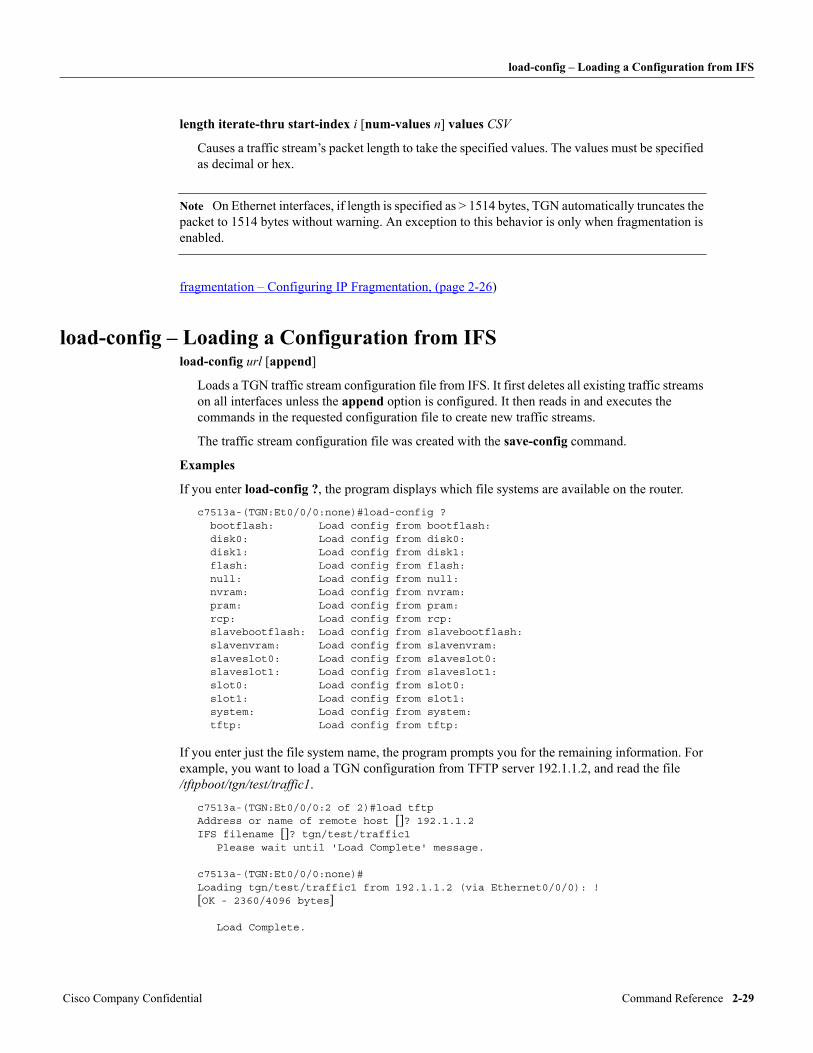
load-config – Loading a Configuration from IFS
length iterate-thru start-index i [num-values n] values CSV
Causes a traffic stream’s packet length to take the specified values. The values must be specified as decimal or hex.
Note On Ethernet interfaces, if length is specified as > 1514 bytes, TGN automatically truncates the packet to 1514 bytes without warning. An exception to this behavior is only when fragmentation is enabled.
fragmentation – Configuring IP Fragmentation, (page 2-26)
load-config – Loading a Configuration from IFSload-config url [append]
Loads a TGN traffic stream configuration file from IFS. It first deletes all existing traffic streams on all interfaces unless the append option is configured. It then reads in and executes the commands in the requested configuration file to create new traffic streams.
The traffic stream configuration file was created with the save-config command.
Examples
If you enter load-config ?, the program displays which file systems are available on the router.
c7513a-(TGN:Et0/0/0:none)#load-config ? bootflash: Load config from bootflash: disk0: Load config from disk0: disk1: Load config from disk1: flash: Load config from flash: null: Load config from null: nvram: Load config from nvram: pram: Load config from pram: rcp: Load config from rcp: slavebootflash: Load config from slavebootflash: slavenvram: Load config from slavenvram: slaveslot0: Load config from slaveslot0: slaveslot1: Load config from slaveslot1: slot0: Load config from slot0: slot1: Load config from slot1: system: Load config from system: tftp: Load config from tftp:
If you enter just the file system name, the program prompts you for the remaining information. For example, you want to load a TGN configuration from TFTP server 192.1.1.2, and read the file /tftpboot/tgn/test/traffic1.
c7513a-(TGN:Et0/0/0:2 of 2)#load tftpAddress or name of remote host []? 192.1.1.2IFS filename []? tgn/test/traffic1 Please wait until 'Load Complete' message. c7513a-(TGN:Et0/0/0:none)#Loading tgn/test/traffic1 from 192.1.1.2 (via Ethernet0/0/0): ![OK - 2360/4096 bytes] Load Complete.
Cisco Company Confidential Command Reference 2-29
max-bit-rate – Setting Interface Bandwidth Control
If the complete URL is entered, the program does not prompt for more information. In a TCL script, you must use the complete URL, because CSCCON does not know how to respond to TGN IFS prompts.
The following example shows using the command from the router exec with a complete URL.
c7513a-pagent#tgn load tftp://192.1.1.2/tgn/test/traffic1 Please wait until 'Load Complete' message. c7513a-pagent#Loading tgn/test/traffic1 from 192.1.1.2 (via Ethernet0/0/0): ![OK - 2360/4096 bytes] Load Complete.
If you need help in creating a URL, first open a file using the IFS prompts. You can then use the show global command to see the complete URL.
replace - Selectively replacing IP Address and TCP/UDP Port Number (page 2-36) IOS File System (page 1-10) show global – Displaying Global Parameters (page 2-47)
max-bit-rate – Setting Interface Bandwidth Controlmax-bit-rate {bits-per-second | off}
Specifies the maximum bits-per-second rate allowed on the currently selected interface or, under broadcast mode, all interfaces. It calculates an interval based on the rate and size of the packet just transmitted by TGN. The next scheduled packet on the same interface is transmitted after the interval has elapsed.
Use the keyword off to turn the feature off.
show interface config – Displaying Interface Configurations (page 2-49)
mixed-interface – Defining Traffic Streams on a Mixed Interfacemixed-interface [on | off]
By default, TGN traffic streams are organized in a set of per-interface lists. In mixed interface mode, traffic streams are organized in a single list instead. TGN only sends the traffic streams defined in the mode under which the traffic generation command is issued.
on
TGN traffic streams across different interfaces (but processed by the same CPU) are organized into a single list.
off
TGN traffic streams are organized into multiple lists based on the interface that the traffic stream is associated with.
show global – Displaying Global Parameters (page 2-47)
name – Assigning a Name to a Traffic Streamname character-string
Assigns a name to a traffic stream. The name is limited to 39 characters.
TGN (Traffic GeNerator) User Manual Cisco Company Confidential2-30
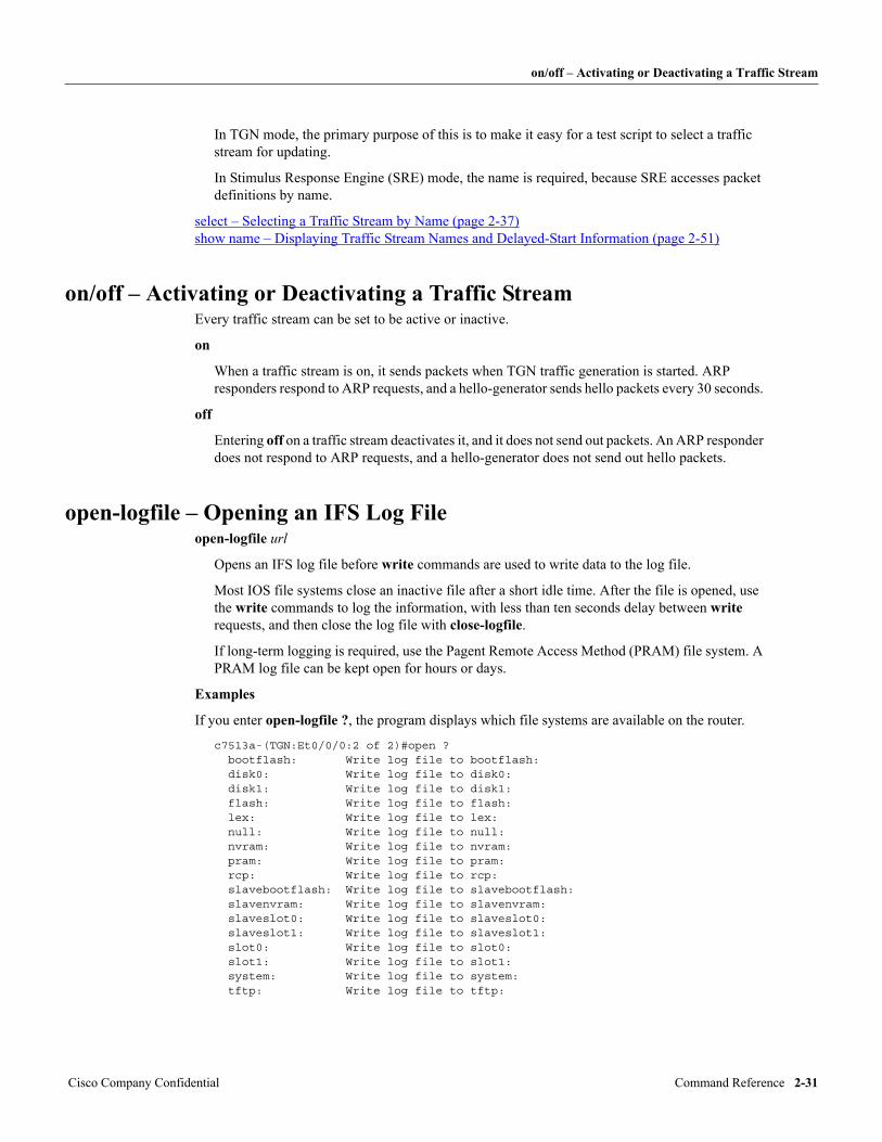
on/off – Activating or Deactivating a Traffic Stream
In TGN mode, the primary purpose of this is to make it easy for a test script to select a traffic stream for updating.
In Stimulus Response Engine (SRE) mode, the name is required, because SRE accesses packet definitions by name.
select – Selecting a Traffic Stream by Name (page 2-37) show name – Displaying Traffic Stream Names and Delayed-Start Information (page 2-51)
on/off – Activating or Deactivating a Traffic StreamEvery traffic stream can be set to be active or inactive.
on
When a traffic stream is on, it sends packets when TGN traffic generation is started. ARP responders respond to ARP requests, and a hello-generator sends hello packets every 30 seconds.
off
Entering off on a traffic stream deactivates it, and it does not send out packets. An ARP responder does not respond to ARP requests, and a hello-generator does not send out hello packets.
open-logfile – Opening an IFS Log Fileopen-logfile url
Opens an IFS log file before write commands are used to write data to the log file.
Most IOS file systems close an inactive file after a short idle time. After the file is opened, use the write commands to log the information, with less than ten seconds delay between write requests, and then close the log file with close-logfile.
If long-term logging is required, use the Pagent Remote Access Method (PRAM) file system. A PRAM log file can be kept open for hours or days.
Examples
If you enter open-logfile ?, the program displays which file systems are available on the router.
c7513a-(TGN:Et0/0/0:2 of 2)#open ? bootflash: Write log file to bootflash: disk0: Write log file to disk0: disk1: Write log file to disk1: flash: Write log file to flash: lex: Write log file to lex: null: Write log file to null: nvram: Write log file to nvram: pram: Write log file to pram: rcp: Write log file to rcp: slavebootflash: Write log file to slavebootflash: slavenvram: Write log file to slavenvram: slaveslot0: Write log file to slaveslot0: slaveslot1: Write log file to slaveslot1: slot0: Write log file to slot0: slot1: Write log file to slot1: system: Write log file to system: tftp: Write log file to tftp:
Cisco Company Confidential Command Reference 2-31
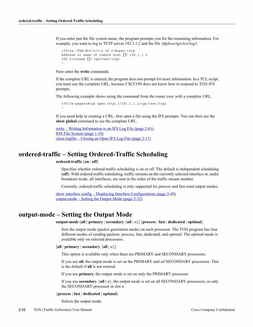
ordered-traffic – Setting Ordered-Traffic Scheduling
If you enter just the file system name, the program prompts you for the remaining information. For example, you want to log to TFTP server 192.1.1.2 and the file /tftpboot/tgn/test/log1.
c7513a-(TGN:Et0/0/0:2 of 2)#open tftpAddress or name of remote host []? 192.1.1.2IFS filename []? tgn/test/log1!
Now enter the write commands.
If the complete URL is entered, the program does not prompt for more information. In a TCL script, you must use the complete URL, because CSCCON does not know how to respond to TGN IFS prompts.
The following example shows using the command from the router exec with a complete URL.
c7513a-pagent#tgn open tftp://192.1.1.2/tgn/test/log1!
If you need help in creating a URL, first open a file using the IFS prompts. You can then use the show global command to see the complete URL.
write – Writing Information to an IFS Log File (page 2-61) IOS File System (page 1-10) close-logfile – Closing an Open IFS Log File (page 2-17)
ordered-traffic – Setting Ordered-Traffic Schedulingordered-traffic [on | off]
Specifies whether ordered-traffic scheduling is on or off. The default is independent scheduling (off). With ordered-traffic scheduling, traffic streams on the currently selected interface or, under broadcast mode, all interfaces, are sent in the order of the traffic stream number.
Currently, ordered-traffic scheduling is only supported for process and fast-send output modes.
show interface config – Displaying Interface Configurations (page 2-49) output-mode – Setting the Output Mode (page 2-32)
output-mode – Setting the Output Modeoutput-mode [all | primary | secondary {all | n}] {process | fast | dedicated | optimal}
Sets the output mode (packet generation mode) on each processor. The TGN program has four different modes of sending packets: process, fast, dedicated, and optimal. The optimal mode is available only on selected processors.
[all | primary | secondary {all | n}]
This option is available only when there are PRIMARY and SECONDARY processors.
If you use all, the output mode is set on the PRIMARY and all SECONDARY processors. This is the default if all is not entered.
If you use primary, the output mode is set on only the PRIMARY processor.
If you use secondary {all | n}, the output mode is set on all SECONDARY processors, or only the SECONDARY processor in slot n.
{process | fast | dedicated | optimal}
Selects the output mode.
TGN (Traffic GeNerator) User Manual Cisco Company Confidential2-32
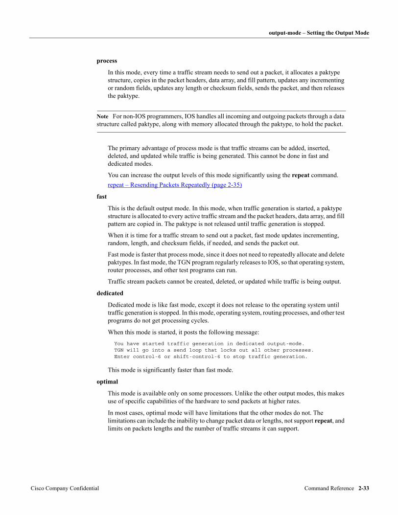
output-mode – Setting the Output Mode
process
In this mode, every time a traffic stream needs to send out a packet, it allocates a paktype structure, copies in the packet headers, data array, and fill pattern, updates any incrementing or random fields, updates any length or checksum fields, sends the packet, and then releases the paktype.
Note For non-IOS programmers, IOS handles all incoming and outgoing packets through a data structure called paktype, along with memory allocated through the paktype, to hold the packet.
The primary advantage of process mode is that traffic streams can be added, inserted, deleted, and updated while traffic is being generated. This cannot be done in fast and dedicated modes.
You can increase the output levels of this mode significantly using the repeat command.repeat – Resending Packets Repeatedly (page 2-35)
fast
This is the default output mode. In this mode, when traffic generation is started, a paktype structure is allocated to every active traffic stream and the packet headers, data array, and fill pattern are copied in. The paktype is not released until traffic generation is stopped.
When it is time for a traffic stream to send out a packet, fast mode updates incrementing, random, length, and checksum fields, if needed, and sends the packet out.
Fast mode is faster that process mode, since it does not need to repeatedly allocate and delete paktypes. In fast mode, the TGN program regularly releases to IOS, so that operating system, router processes, and other test programs can run.
Traffic stream packets cannot be created, deleted, or updated while traffic is being output.
dedicated
Dedicated mode is like fast mode, except it does not release to the operating system until traffic generation is stopped. In this mode, operating system, routing processes, and other test programs do not get processing cycles.
When this mode is started, it posts the following message:
You have started traffic generation in dedicated output-mode. TGN will go into a send loop that locks out all other processes.Enter control-6 or shift-control-6 to stop traffic generation.
This mode is significantly faster than fast mode.
optimal
This mode is available only on some processors. Unlike the other output modes, this makes use of specific capabilities of the hardware to send packets at higher rates.
In most cases, optimal mode will have limitations that the other modes do not. The limitations can include the inability to change packet data or lengths, not support repeat, and limits on packets lengths and the number of traffic streams it can support.
Cisco Company Confidential Command Reference 2-33
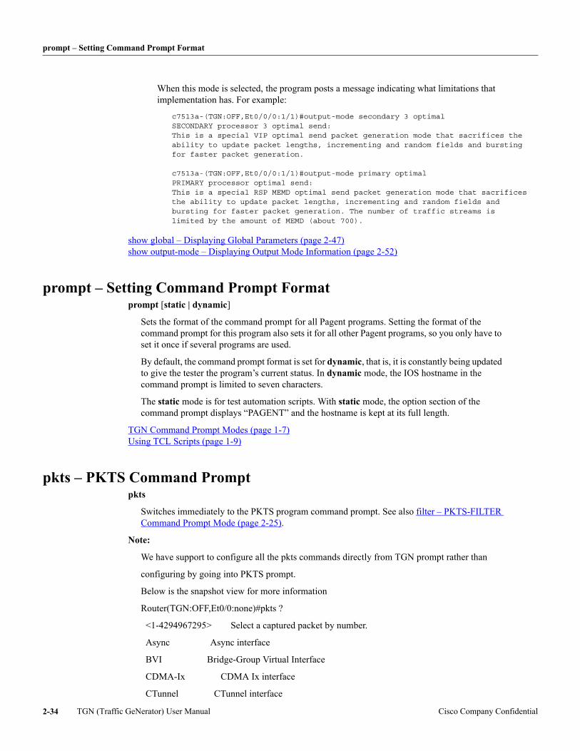
prompt – Setting Command Prompt Format
When this mode is selected, the program posts a message indicating what limitations that implementation has. For example:
c7513a-(TGN:OFF,Et0/0/0:1/1)#output-mode secondary 3 optimal SECONDARY processor 3 optimal send: This is a special VIP optimal send packet generation mode that sacrifices the ability to update packet lengths, incrementing and random fields and bursting for faster packet generation. c7513a-(TGN:OFF,Et0/0/0:1/1)#output-mode primary optimal PRIMARY processor optimal send: This is a special RSP MEMD optimal send packet generation mode that sacrifices the ability to update packet lengths, incrementing and random fields and bursting for faster packet generation. The number of traffic streams is limited by the amount of MEMD (about 700).
show global – Displaying Global Parameters (page 2-47) show output-mode – Displaying Output Mode Information (page 2-52)
prompt – Setting Command Prompt Formatprompt [static | dynamic]
Sets the format of the command prompt for all Pagent programs. Setting the format of the command prompt for this program also sets it for all other Pagent programs, so you only have to set it once if several programs are used.
By default, the command prompt format is set for dynamic, that is, it is constantly being updated to give the tester the program’s current status. In dynamic mode, the IOS hostname in the command prompt is limited to seven characters.
The static mode is for test automation scripts. With static mode, the option section of the command prompt displays “PAGENT” and the hostname is kept at its full length.
TGN Command Prompt Modes (page 1-7) Using TCL Scripts (page 1-9)
pkts – PKTS Command Promptpkts
Switches immediately to the PKTS program command prompt. See also filter – PKTS-FILTER Command Prompt Mode (page 2-25).
Note:
We have support to configure all the pkts commands directly from TGN prompt rather than
configuring by going into PKTS prompt.
Below is the snapshot view for more information
Router(TGN:OFF,Et0/0:none)#pkts ?
<1-4294967295> Select a captured packet by number.
Async Async interface
BVI Bridge-Group Virtual Interface
CDMA-Ix CDMA Ix interface
CTunnel CTunnel interface
TGN (Traffic GeNerator) User Manual Cisco Company Confidential2-34
rate – Setting the Packet Send Rate
Dialer Dialer interface
Ethernet IEEE 802.3
Group-Async Async Group interface
Lex Lex interface
Loopback Loopback interface
MFR Multilink Frame Relay bundle interface
Multilink Multilink-group interface
Null Null interface
Serial Serial
Tunnel Tunnel interface
Vif PGM Multicast Host interface
Virtual-PPP Virtual PPP interface
Virtual-Template Virtual Template interface
Virtual-TokenRing Virtual TokenRing
add-capture-buffer Create packet capture buffer in router memory.
assign Configure how to decode UDP port numbers.
clear Clear interface configs, filters.
--More--
rate – Setting the Packet Send Raterate packets-per-second
Sets the rate that a traffic stream sends packets. To define a slow rate, use the interval command. To define rate in bits per second, use the bit-rate command.
interval – Setting the Interval Between Sending Packets (page 2-27) bit-rate - Setting the transmission Rate in bits per second (page 2-15) variability – Defining the Variability in Packet Intervals (page 2-60) show rate – Displaying Traffic Stream Rates (page 2-55)
repeat – Resending Packets Repeatedlyrepeat #packets [with-update | no-update]
Determines how many packets a traffic stream puts repeatedly on the output queue as fast as possible before looking for the next traffic stream ready to send packets. The default is 1, which means no looping.
with-update
Updates traffic streams with incrementing, iterating, or random packet lengths or fields with each packet sent. By default, a traffic stream is defined with no update on repeat.
no-update
Cisco Company Confidential Command Reference 2-35
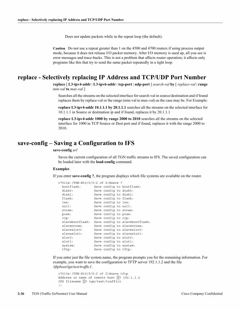
replace - Selectively replacing IP Address and TCP/UDP Port Number
Does not update packets while in the repeat loop (the default).
Caution Do not use a repeat greater than 1 on the 4500 and 4700 routers if using process output mode, because it does not release I/O packet memory. After I/O memory is used up, all you see is error messages and trace-backs. This is not a problem that affects router operation; it affects only programs like this that try to send the same packet repeatedly in a tight loop.
replace - Selectively replacing IP Address and TCP/UDP Port Numberreplace [ L3-ipv4-addr | L3-ipv6-addr | tcp-port | udp-port ] search-val by [ replace-val | range min-val to max-val ]
Searches all the streams on the selected interface for search-val in source/destination and if found replaces them by replace-val or the range (min-val to max-val) as the case may be. For Example:
replace L3-ipv4-addr 10.1.1.1 by 20.1.1.1 searches all the streams on the selected interface for 10.1.1.1 in Source or destination ip and if found, replaces it by 20.1.1.1
replace L3-ipv4-addr 1000 by range 2000 to 2010 searches all the streams on the selected interface for 1000 in TCP Source or Dest port and if found, replaces it with the range 2000 to 2010.
save-config – Saving a Configuration to IFSsave-config url
Saves the current configuration of all TGN traffic streams to IFS. The saved configuration can be loaded later with the load-config command.
Examples
If you enter save-config ?, the program displays which file systems are available on the router.
c7513a-(TGN:Et0/0/0:2 of 2)#save ? bootflash: Save config to bootflash: disk0: Save config to disk0: disk1: Save config to disk1: flash: Save config to flash: lex: Save config to lex: null: Save config to null: nvram: Save config to nvram: pram: Save config to pram: rcp: Save config to rcp: slavebootflash: Save config to slavebootflash: slavenvram: Save config to slavenvram: slaveslot0: Save config to slaveslot0: slaveslot1: Save config to slaveslot1: slot0: Save config to slot0: slot1: Save config to slot1: system: Save config to system: tftp: Save config to tftp:
If you enter just the file system name, the program prompts you for the remaining information. For example, you want to save the configuration to TFTP server 192.1.1.2 and the file /tftpboot/tgn/test/traffic1.
c7513a-(TGN:Et0/0/0:2 of 2)#save tftpAddress or name of remote host []? 192.1.1.2IFS filename []? tgn/test/traffic1!!
TGN (Traffic GeNerator) User Manual Cisco Company Confidential2-36
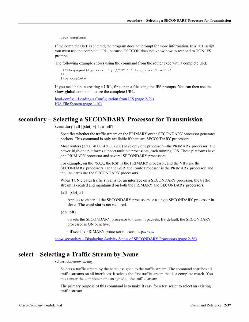
secondary – Selecting a SECONDARY Processor for Transmission
Save complete.
If the complete URL is entered, the program does not prompt for more information. In a TCL script, you must use the complete URL, because CSCCON does not know how to respond to TGN IFS prompts.
The following example shows using the command from the router exec with a complete URL.
c7513a-pagent#tgn save tftp://192.1.1.2/tgn/test/traffic1!!Save complete.
If you need help in creating a URL, first open a file using the IFS prompts. You can then use the show global command to see the complete URL.
load-config – Loading a Configuration from IFS (page 2-29) IOS File System (page 1-10)
secondary – Selecting a SECONDARY Processor for Transmissionsecondary {all | [slot] n} {on | off}
Specifies whether the traffic stream on the PRIMARY or the SECONDARY processor generates packets. This command is only available if there are SECONDARY processors.
Most routers (2500, 4000, 4500, 7200) have only one processor—the PRIMARY processor. The newer, high-end platforms support multiple processors, each running IOS. These platforms have one PRIMARY processor and several SECONDARY processors.
For example, on the 75XX, the RSP is the PRIMARY processor, and the VIPs are the SECONDARY processors. On the GSR, the Route Processor is the PRIMARY processor, and the line cards are the SECONDARY processors.
When TGN creates traffic streams for an interface on a SECONDARY processor, the traffic stream is created and maintained on both the PRIMARY and SECONDARY processors.
{all | [slot] n}
Applies to either all the SECONDARY processors or a single SECONDARY processor in slot n. The word slot is not required.
{on | off}
on sets the SECONDARY processor to transmit packets. By default, the SECONDARY processor is ON or active.
off sets the PRIMARY processor to transmit packets.
show secondary – Displaying Activity Status of SECONDARY Processors (page 2-56)
select – Selecting a Traffic Stream by Nameselect character-string
Selects a traffic stream by the name assigned to the traffic stream. The command searches all traffic streams on all interfaces. It selects the first traffic stream that is a complete match. You must enter the complete name assigned to the traffic stream.
The primary purpose of this command is to make it easy for a test script to select an existing traffic stream.
Cisco Company Confidential Command Reference 2-37
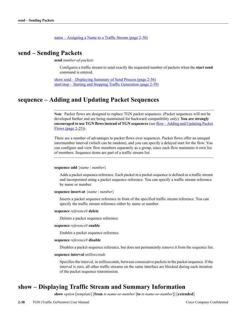
send – Sending Packets
name – Assigning a Name to a Traffic Stream (page 2-30)
send – Sending Packetssend number-of-packets
Configures a traffic stream to send exactly the requested number of packets when the start send command is entered.
show send – Displaying Summary of Send Process (page 2-56) start/stop – Starting and Stopping Traffic Generation (page 2-59)
sequence – Adding and Updating Packet Sequences
Note Packet flows are designed to replace TGN packet sequences. (Packet sequences will not be developed further and are being maintained for backward compatibility only). You are strongly encouraged to use TGN flows instead of TGN sequences (see flow – Adding and Updating Packet Flows (page 2-25)). There are a number of advantages to packet flows over sequences. Packet flows offer an unequal intermember interval (which can be random), and you can specify a delayed start for the flow. You can configure and view flow members separately as a group, since each flow maintains it own list of members. Sequence items are part of a traffic stream list.
sequence add {name | number}
Adds a packet sequence reference. Each packet in a packet sequence is defined as a traffic stream and incorporated using a packet sequence reference. You can specify a traffic stream reference by name or number.
sequence insert-at {name | number}
Inserts a packet sequence reference in front of the specified traffic stream reference. You can specify the traffic stream reference either by name or number.
sequence reference# delete
Deletes a packet sequence reference.
sequence reference# enable
Enables a packet sequence reference.
sequence reference# disable
Disables a packet sequence reference, but does not permanently remove it from the sequence list.
sequence interval milliseconds
Specifies the interval, in milliseconds, between consecutive packets in the packet sequence. If the interval is zero, all other traffic streams on the same interface are blocked during each iteration of the packet sequence transmission.
show – Displaying Traffic Stream and Summary Informationshow option [template] [from ts-name-or-number [to ts-name-or-number]] [extended]
TGN (Traffic GeNerator) User Manual Cisco Company Confidential2-38
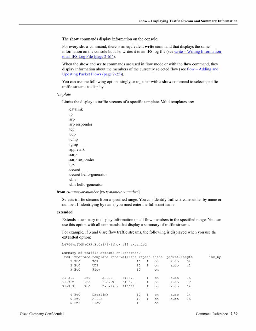
show – Displaying Traffic Stream and Summary Information
The show commands display information on the console.
For every show command, there is an equivalent write command that displays the same information on the console but also writes it to an IFS log file (see write – Writing Information to an IFS Log File (page 2-61)).
When the show and write commands are used in flow mode or with the flow command, they display information about the members of the currently selected flow (see flow – Adding and Updating Packet Flows (page 2-25)).
You can use the following options singly or together with a show command to select specific traffic streams to display.
template
Limits the display to traffic streams of a specific template. Valid templates are:
datalink ip arp arp responder tcp udp icmp igmp appletalk aarp aarp responder ipx decnet decnet hello-generator clns clns hello-generator
from ts-name-or-number [to ts-name-or-number]
Selects traffic streams from a specified range. You can identify traffic streams either by name or number. If identifying by name, you must enter the full exact name.
extended
Extends a summary to display information on all flow members in the specified range. You can use this option with all commands that display a summary of traffic streams.
For example, if 3 and 6 are flow traffic streams, the following is displayed when you use the extended option:
k4700-p(TGN:OFF,Et0:6/9)#show all extended
Summary of traffic streams on Ethernet0 ts# interface template interval/rate repeat state packet.length inc_by 1 Et0 TCP 10 1 on auto 54 2 Et0 UDP 10 1 on auto 42 3 Et0 Flow 10 on
Fl-3.1 Et0 APPLE 345678 1 on auto 35Fl-3.2 Et0 DECNET 345678 1 on auto 37Fl-3.3 Et0 Datalink 345678 1 on auto 14
4 Et0 Datalink 10 1 on auto 14 5 Et0 APPLE 10 1 on auto 35 6 Et0 Flow 10 on
Cisco Company Confidential Command Reference 2-39
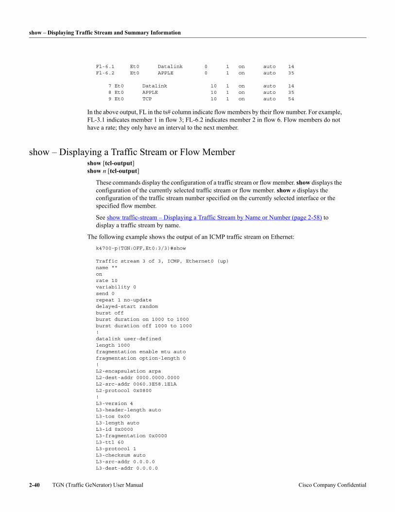
show – Displaying Traffic Stream and Summary Information
Fl-6.1 Et0 Datalink 0 1 on auto 14Fl-6.2 Et0 APPLE 0 1 on auto 35
7 Et0 Datalink 10 1 on auto 14 8 Et0 APPLE 10 1 on auto 35 9 Et0 TCP 10 1 on auto 54
In the above output, FL in the ts# column indicate flow members by their flow number. For example, FL-3.1 indicates member 1 in flow 3; FL-6.2 indicates member 2 in flow 6. Flow members do not have a rate; they only have an interval to the next member.
show – Displaying a Traffic Stream or Flow Membershow [tcl-output] show n [tcl-output]
These commands display the configuration of a traffic stream or flow member. show displays the configuration of the currently selected traffic stream or flow member. show n displays the configuration of the traffic stream number specified on the currently selected interface or the specified flow member.
See show traffic-stream – Displaying a Traffic Stream by Name or Number (page 2-58) to display a traffic stream by name.
The following example shows the output of an ICMP traffic stream on Ethernet:
k4700-p(TGN:OFF,Et0:3/3)#show
Traffic stream 3 of 3, ICMP, Ethernet0 (up)name ""onrate 10variability 0send 0repeat 1 no-updatedelayed-start randomburst offburst duration on 1000 to 1000burst duration off 1000 to 1000!datalink user-definedlength 1000fragmentation enable mtu autofragmentation option-length 0!L2-encapsulation arpaL2-dest-addr 0000.0000.0000L2-src-addr 0060.3E58.1E1AL2-protocol 0x0800!L3-version 4L3-header-length autoL3-tos 0x00L3-length autoL3-id 0x0000L3-fragmentation 0x0000L3-ttl 60L3-protocol 1L3-checksum autoL3-src-addr 0.0.0.0L3-dest-addr 0.0.0.0
TGN (Traffic GeNerator) User Manual Cisco Company Confidential2-40
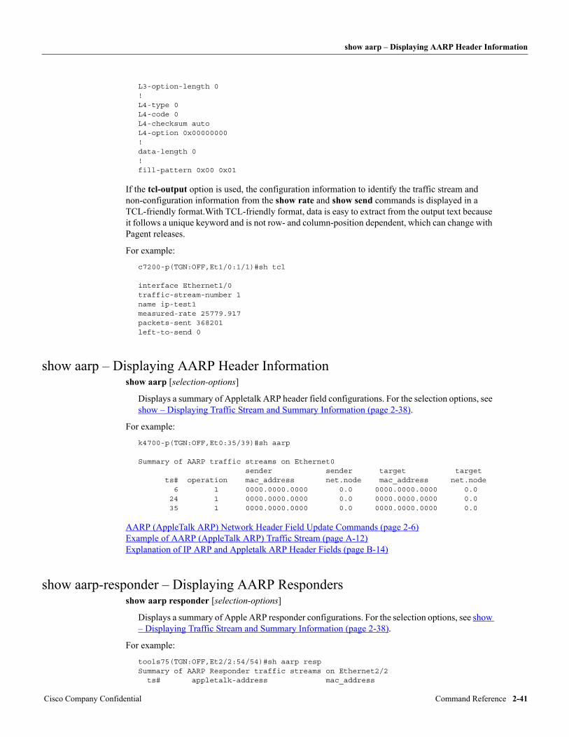
show aarp – Displaying AARP Header Information
L3-option-length 0!L4-type 0L4-code 0L4-checksum autoL4-option 0x00000000!data-length 0!fill-pattern 0x00 0x01
If the tcl-output option is used, the configuration information to identify the traffic stream and non-configuration information from the show rate and show send commands is displayed in a TCL-friendly format.With TCL-friendly format, data is easy to extract from the output text because it follows a unique keyword and is not row- and column-position dependent, which can change with Pagent releases.
For example:
c7200-p(TGN:OFF,Et1/0:1/1)#sh tcl
interface Ethernet1/0traffic-stream-number 1name ip-test1measured-rate 25779.917packets-sent 368201left-to-send 0
show aarp – Displaying AARP Header Informationshow aarp [selection-options]
Displays a summary of Appletalk ARP header field configurations. For the selection options, see show – Displaying Traffic Stream and Summary Information (page 2-38).
For example:
k4700-p(TGN:OFF,Et0:35/39)#sh aarp
Summary of AARP traffic streams on Ethernet0 sender sender target target ts# operation mac_address net.node mac_address net.node 6 1 0000.0000.0000 0.0 0000.0000.0000 0.0 24 1 0000.0000.0000 0.0 0000.0000.0000 0.0 35 1 0000.0000.0000 0.0 0000.0000.0000 0.0
AARP (AppleTalk ARP) Network Header Field Update Commands (page 2-6) Example of AARP (AppleTalk ARP) Traffic Stream (page A-12) Explanation of IP ARP and Appletalk ARP Header Fields (page B-14)
show aarp-responder – Displaying AARP Respondersshow aarp responder [selection-options]
Displays a summary of Apple ARP responder configurations. For the selection options, see show – Displaying Traffic Stream and Summary Information (page 2-38).
For example:
tools75(TGN:OFF,Et2/2:54/54)#sh aarp respSummary of AARP Responder traffic streams on Ethernet2/2 ts# appletalk-address mac_address
Cisco Company Confidential Command Reference 2-41
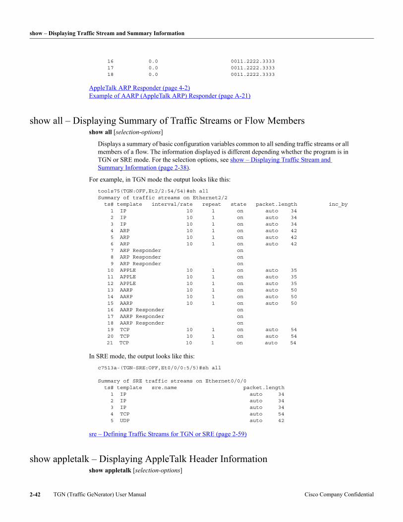
show – Displaying Traffic Stream and Summary Information
16 0.0 0011.2222.3333 17 0.0 0011.2222.3333 18 0.0 0011.2222.3333
AppleTalk ARP Responder (page 4-2) Example of AARP (AppleTalk ARP) Responder (page A-21)
show all – Displaying Summary of Traffic Streams or Flow Membersshow all [selection-options]
Displays a summary of basic configuration variables common to all sending traffic streams or all members of a flow. The information displayed is different depending whether the program is in TGN or SRE mode. For the selection options, see show – Displaying Traffic Stream and Summary Information (page 2-38).
For example, in TGN mode the output looks like this:
tools75(TGN:OFF,Et2/2:54/54)#sh all Summary of traffic streams on Ethernet2/2 ts# template interval/rate repeat state packet.length inc_by 1 IP 10 1 on auto 34 2 IP 10 1 on auto 34 3 IP 10 1 on auto 34 4 ARP 10 1 on auto 42 5 ARP 10 1 on auto 42 6 ARP 10 1 on auto 42 7 ARP Responder on 8 ARP Responder on 9 ARP Responder on 10 APPLE 10 1 on auto 35 11 APPLE 10 1 on auto 35 12 APPLE 10 1 on auto 35 13 AARP 10 1 on auto 50 14 AARP 10 1 on auto 50 15 AARP 10 1 on auto 50 16 AARP Responder on 17 AARP Responder on 18 AARP Responder on 19 TCP 10 1 on auto 54 20 TCP 10 1 on auto 54
21 TCP 10 1 on auto 54
In SRE mode, the output looks like this:
c7513a-(TGN-SRE:OFF,Et0/0/0:5/5)#sh all Summary of SRE traffic streams on Ethernet0/0/0 ts# template sre.name packet.length 1 IP auto 34 2 IP auto 34 3 IP auto 34 4 TCP auto 54 5 UDP auto 42
sre – Defining Traffic Streams for TGN or SRE (page 2-59)
show appletalk – Displaying AppleTalk Header Informationshow appletalk [selection-options]
TGN (Traffic GeNerator) User Manual Cisco Company Confidential2-42
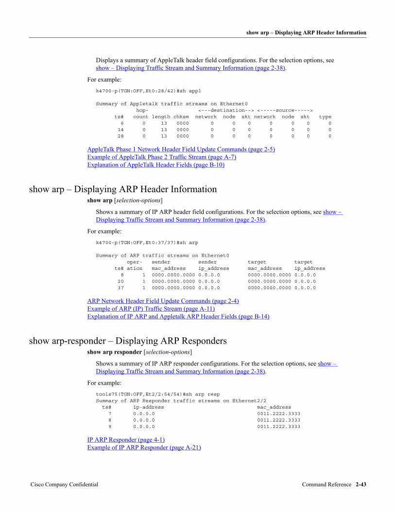
show arp – Displaying ARP Header Information
Displays a summary of AppleTalk header field configurations. For the selection options, see show – Displaying Traffic Stream and Summary Information (page 2-38).
For example:
k4700-p(TGN:OFF,Et0:28/42)#sh appl
Summary of Appletalk traffic streams on Ethernet0 hop- <---destination--> <-----source-----> ts# count length chksm network node skt network node skt type 6 0 13 0000 0 0 0 0 0 0 0 14 0 13 0000 0 0 0 0 0 0 0 28 0 13 0000 0 0 0 0 0 0 0
AppleTalk Phase 1 Network Header Field Update Commands (page 2-5) Example of AppleTalk Phase 2 Traffic Stream (page A-7) Explanation of AppleTalk Header Fields (page B-10)
show arp – Displaying ARP Header Informationshow arp [selection-options]
Shows a summary of IP ARP header field configurations. For the selection options, see show – Displaying Traffic Stream and Summary Information (page 2-38).
For example:
k4700-p(TGN:OFF,Et0:37/37)#sh arp
Summary of ARP traffic streams on Ethernet0 oper- sender sender target target ts# ation mac_address ip_address mac_address ip_address 8 1 0000.0000.0000 0.0.0.0 0000.0000.0000 0.0.0.0 20 1 0000.0000.0000 0.0.0.0 0000.0000.0000 0.0.0.0 37 1 0000.0000.0000 0.0.0.0 0000.0000.0000 0.0.0.0
ARP Network Header Field Update Commands (page 2-4) Example of ARP (IP) Traffic Stream (page A-11) Explanation of IP ARP and Appletalk ARP Header Fields (page B-14)
show arp-responder – Displaying ARP Respondersshow arp responder [selection-options]
Shows a summary of IP ARP responder configurations. For the selection options, see show – Displaying Traffic Stream and Summary Information (page 2-38).
For example:
tools75(TGN:OFF,Et2/2:54/54)#sh arp respSummary of ARP Responder traffic streams on Ethernet2/2 ts# ip-address mac_address 7 0.0.0.0 0011.2222.3333 8 0.0.0.0 0011.2222.3333 9 0.0.0.0 0011.2222.3333
IP ARP Responder (page 4-1) Example of IP ARP Responder (page A-21)
Cisco Company Confidential Command Reference 2-43
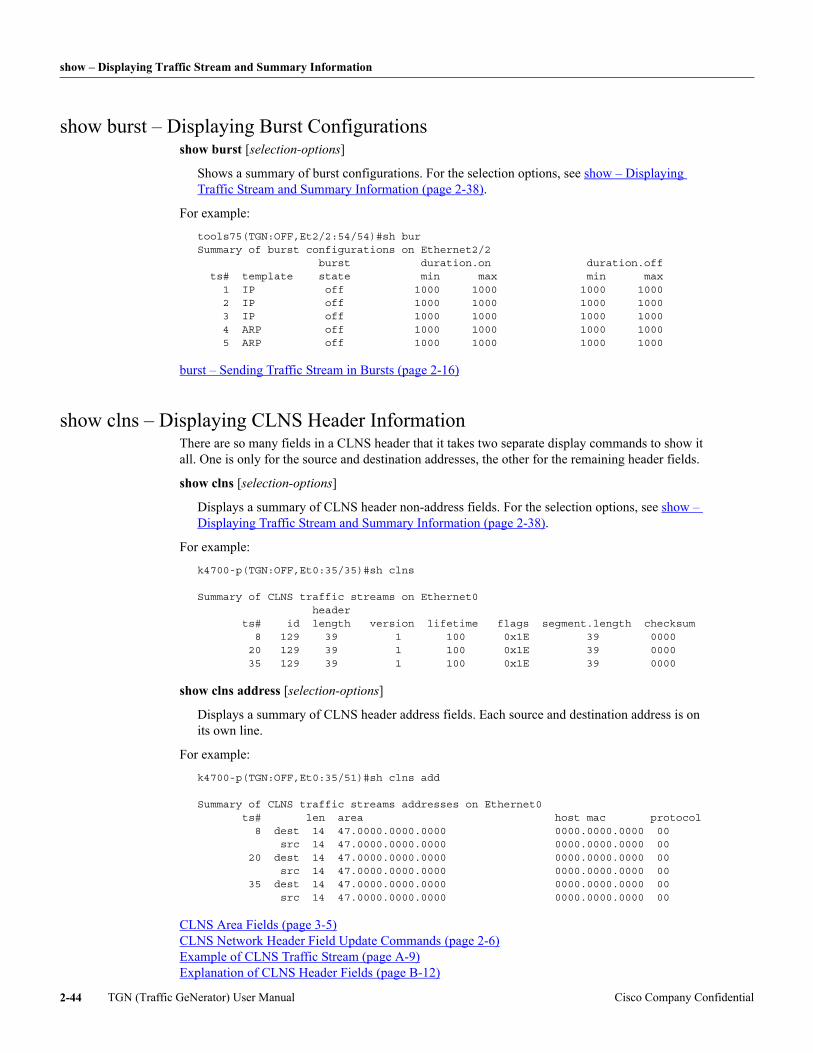
show – Displaying Traffic Stream and Summary Information
show burst – Displaying Burst Configurationsshow burst [selection-options]
Shows a summary of burst configurations. For the selection options, see show – Displaying Traffic Stream and Summary Information (page 2-38).
For example:
tools75(TGN:OFF,Et2/2:54/54)#sh burSummary of burst configurations on Ethernet2/2 burst duration.on duration.off ts# template state min max min max 1 IP off 1000 1000 1000 1000 2 IP off 1000 1000 1000 1000 3 IP off 1000 1000 1000 1000 4 ARP off 1000 1000 1000 1000 5 ARP off 1000 1000 1000 1000
burst – Sending Traffic Stream in Bursts (page 2-16)
show clns – Displaying CLNS Header InformationThere are so many fields in a CLNS header that it takes two separate display commands to show it all. One is only for the source and destination addresses, the other for the remaining header fields.
show clns [selection-options]
Displays a summary of CLNS header non-address fields. For the selection options, see show – Displaying Traffic Stream and Summary Information (page 2-38).
For example:
k4700-p(TGN:OFF,Et0:35/35)#sh clns
Summary of CLNS traffic streams on Ethernet0 header ts# id length version lifetime flags segment.length checksum 8 129 39 1 100 0x1E 39 0000 20 129 39 1 100 0x1E 39 0000 35 129 39 1 100 0x1E 39 0000
show clns address [selection-options]
Displays a summary of CLNS header address fields. Each source and destination address is on its own line.
For example:
k4700-p(TGN:OFF,Et0:35/51)#sh clns add
Summary of CLNS traffic streams addresses on Ethernet0 ts# len area host mac protocol 8 dest 14 47.0000.0000.0000 0000.0000.0000 00 src 14 47.0000.0000.0000 0000.0000.0000 00 20 dest 14 47.0000.0000.0000 0000.0000.0000 00 src 14 47.0000.0000.0000 0000.0000.0000 00 35 dest 14 47.0000.0000.0000 0000.0000.0000 00 src 14 47.0000.0000.0000 0000.0000.0000 00
CLNS Area Fields (page 3-5) CLNS Network Header Field Update Commands (page 2-6) Example of CLNS Traffic Stream (page A-9) Explanation of CLNS Header Fields (page B-12)
TGN (Traffic GeNerator) User Manual Cisco Company Confidential2-44
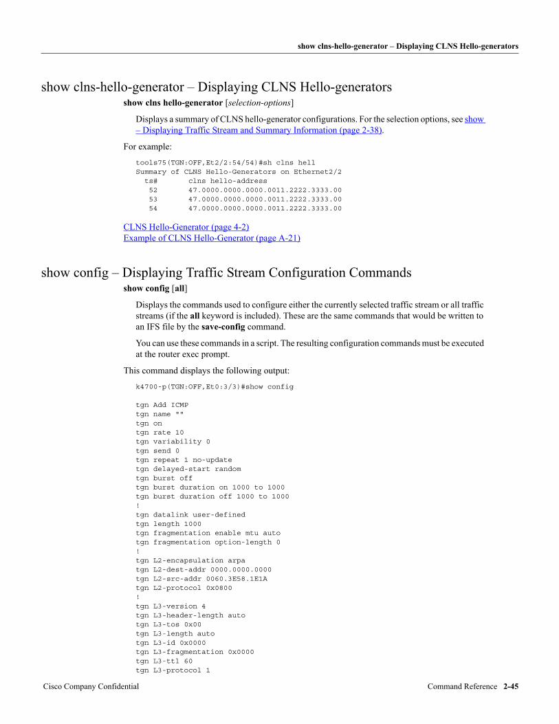
show clns-hello-generator – Displaying CLNS Hello-generators
show clns-hello-generator – Displaying CLNS Hello-generatorsshow clns hello-generator [selection-options]
Displays a summary of CLNS hello-generator configurations. For the selection options, see show – Displaying Traffic Stream and Summary Information (page 2-38).
For example:
tools75(TGN:OFF,Et2/2:54/54)#sh clns hellSummary of CLNS Hello-Generators on Ethernet2/2 ts# clns hello-address 52 47.0000.0000.0000.0011.2222.3333.00 53 47.0000.0000.0000.0011.2222.3333.00 54 47.0000.0000.0000.0011.2222.3333.00
CLNS Hello-Generator (page 4-2) Example of CLNS Hello-Generator (page A-21)
show config – Displaying Traffic Stream Configuration Commandsshow config [all]
Displays the commands used to configure either the currently selected traffic stream or all traffic streams (if the all keyword is included). These are the same commands that would be written to an IFS file by the save-config command.
You can use these commands in a script. The resulting configuration commands must be executed at the router exec prompt.
This command displays the following output:
k4700-p(TGN:OFF,Et0:3/3)#show config
tgn Add ICMPtgn name ""tgn ontgn rate 10tgn variability 0tgn send 0tgn repeat 1 no-updatetgn delayed-start randomtgn burst offtgn burst duration on 1000 to 1000tgn burst duration off 1000 to 1000!tgn datalink user-definedtgn length 1000tgn fragmentation enable mtu autotgn fragmentation option-length 0!tgn L2-encapsulation arpatgn L2-dest-addr 0000.0000.0000tgn L2-src-addr 0060.3E58.1E1Atgn L2-protocol 0x0800!tgn L3-version 4tgn L3-header-length autotgn L3-tos 0x00tgn L3-length autotgn L3-id 0x0000tgn L3-fragmentation 0x0000tgn L3-ttl 60tgn L3-protocol 1
Cisco Company Confidential Command Reference 2-45
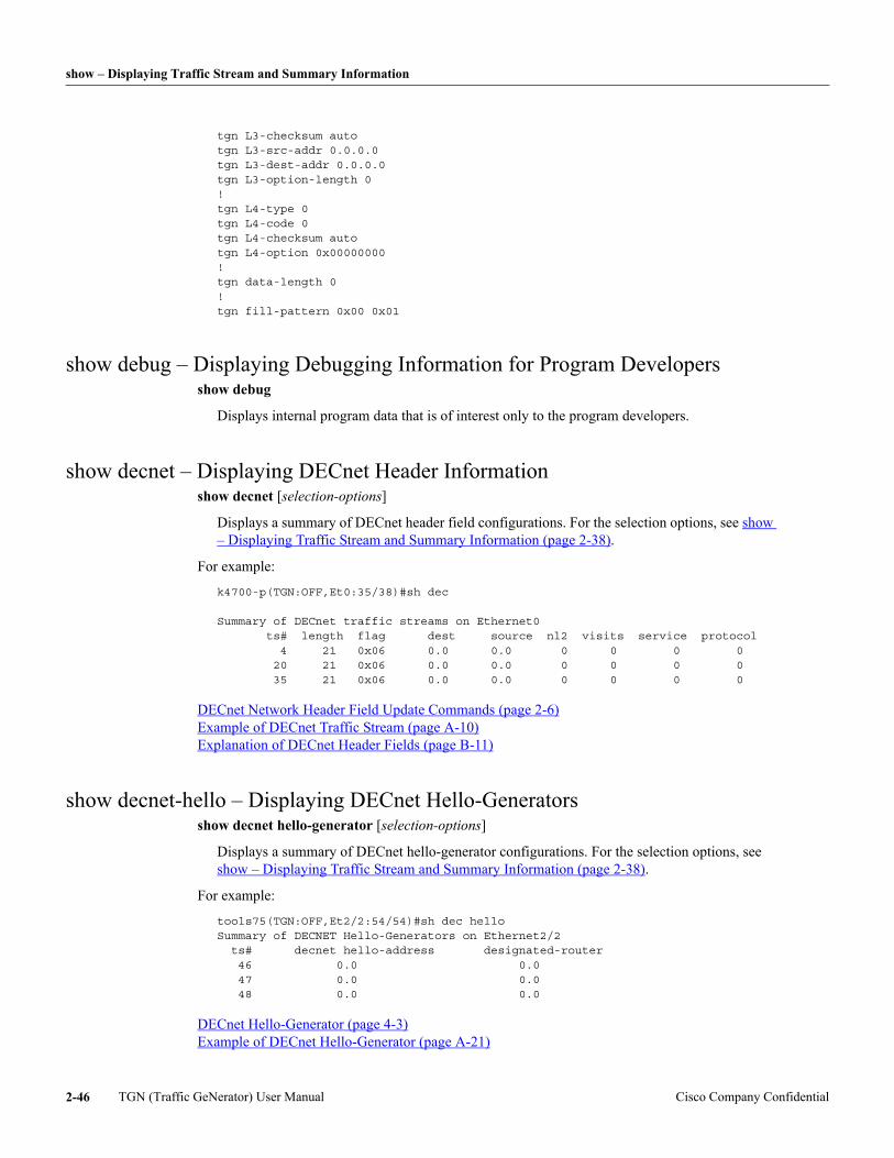
show – Displaying Traffic Stream and Summary Information
tgn L3-checksum autotgn L3-src-addr 0.0.0.0tgn L3-dest-addr 0.0.0.0tgn L3-option-length 0!tgn L4-type 0tgn L4-code 0tgn L4-checksum autotgn L4-option 0x00000000!tgn data-length 0!tgn fill-pattern 0x00 0x01
show debug – Displaying Debugging Information for Program Developersshow debug
Displays internal program data that is of interest only to the program developers.
show decnet – Displaying DECnet Header Informationshow decnet [selection-options]
Displays a summary of DECnet header field configurations. For the selection options, see show – Displaying Traffic Stream and Summary Information (page 2-38).
For example:
k4700-p(TGN:OFF,Et0:35/38)#sh dec
Summary of DECnet traffic streams on Ethernet0 ts# length flag dest source nl2 visits service protocol 4 21 0x06 0.0 0.0 0 0 0 0 20 21 0x06 0.0 0.0 0 0 0 0 35 21 0x06 0.0 0.0 0 0 0 0
DECnet Network Header Field Update Commands (page 2-6) Example of DECnet Traffic Stream (page A-10) Explanation of DECnet Header Fields (page B-11)
show decnet-hello – Displaying DECnet Hello-Generatorsshow decnet hello-generator [selection-options]
Displays a summary of DECnet hello-generator configurations. For the selection options, see show – Displaying Traffic Stream and Summary Information (page 2-38).
For example:
tools75(TGN:OFF,Et2/2:54/54)#sh dec helloSummary of DECNET Hello-Generators on Ethernet2/2 ts# decnet hello-address designated-router 46 0.0 0.0 47 0.0 0.0 48 0.0 0.0
DECnet Hello-Generator (page 4-3) Example of DECnet Hello-Generator (page A-21)
TGN (Traffic GeNerator) User Manual Cisco Company Confidential2-46
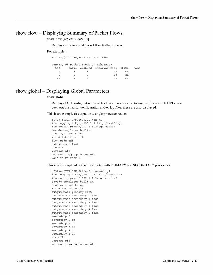
show flow – Displaying Summary of Packet Flows
show flow – Displaying Summary of Packet Flowsshow flow [selection-options]
Displays a summary of packet flow traffic streams.
For example:
k4700-p(TGN:OFF,Et0:10/10)#sh flow
Summary of packet flows on Ethernet0 ts# total enabled interval/rate state name 3 5 5 10 on 6 5 3 10 on 10 3 0 10 on
show global – Displaying Global Parametersshow global
Displays TGN configuration variables that are not specific to any traffic stream. If URLs have been established for configuration and/or log files, these are also displayed.
This is an example of output on a single processor router:
c4700-p(TGN:OFF,Et1:2/2)#sh glifs logging tftp://192.1.1.2/tgn/test/log1ifs config pram://192.1.1.2/tgn-configdecode-templates built-indisplay-level tersemixed-interface offflow-mode offoutput-mode fastsre offverbose offverbose logging-to consolewait-to-release 1
This is an example of output on a router with PRIMARY and SECONDARY processors:
c7513a-(TGN:OFF,Et0/0/0:none)#sh glifs logging tftp://192.1.1.2/tgn/test/log2ifs config pram://192.1.1.2/tgn-config2decode-templates built-indisplay-level tersemixed-interface offoutput-mode primary fastoutput-mode secondary 0 fastoutput-mode secondary 1 fastoutput-mode secondary 2 fastoutput-mode secondary 3 fastoutput-mode secondary 4 fastoutput-mode secondary 5 fastsecondary 0 onsecondary 1 onsecondary 2 onsecondary 3 onsecondary 4 onsecondary 5 onsre offverbose offverbose logging-to console
Cisco Company Confidential Command Reference 2-47
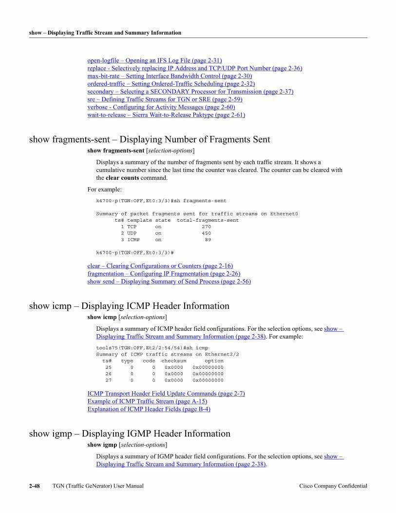
show – Displaying Traffic Stream and Summary Information
open-logfile – Opening an IFS Log File (page 2-31) replace - Selectively replacing IP Address and TCP/UDP Port Number (page 2-36) max-bit-rate – Setting Interface Bandwidth Control (page 2-30) ordered-traffic – Setting Ordered-Traffic Scheduling (page 2-32) secondary – Selecting a SECONDARY Processor for Transmission (page 2-37) sre – Defining Traffic Streams for TGN or SRE (page 2-59) verbose - Configuring for Activity Messages (page 2-60) wait-to-release – Sierra Wait-to-Release Paktype (page 2-61)
show fragments-sent – Displaying Number of Fragments Sentshow fragments-sent [selection-options]
Displays a summary of the number of fragments sent by each traffic stream. It shows a cumulative number since the last time the counter was cleared. The counter can be cleared with the clear counts command.
For example:
k4700-p(TGN:OFF,Et0:3/3)#sh fragments-sent
Summary of packet fragments sent for traffic streams on Ethernet0 ts# template state total-fragments-sent 1 TCP on 270 2 UDP on 450 3 ICMP on 89
k4700-p(TGN:OFF,Et0:3/3)#
clear – Clearing Configurations or Counters (page 2-16) fragmentation – Configuring IP Fragmentation (page 2-26) show send – Displaying Summary of Send Process (page 2-56)
show icmp – Displaying ICMP Header Informationshow icmp [selection-options]
Displays a summary of ICMP header field configurations. For the selection options, see show – Displaying Traffic Stream and Summary Information (page 2-38). For example:
tools75(TGN:OFF,Et2/2:54/54)#sh icmpSummary of ICMP traffic streams on Ethernet2/2 ts# type code checksum option 25 0 0 0x0000 0x00000000 26 0 0 0x0000 0x00000000 27 0 0 0x0000 0x00000000
ICMP Transport Header Field Update Commands (page 2-7) Example of ICMP Traffic Stream (page A-15) Explanation of ICMP Header Fields (page B-4)
show igmp – Displaying IGMP Header Informationshow igmp [selection-options]
Displays a summary of IGMP header field configurations. For the selection options, see show – Displaying Traffic Stream and Summary Information (page 2-38).
TGN (Traffic GeNerator) User Manual Cisco Company Confidential2-48
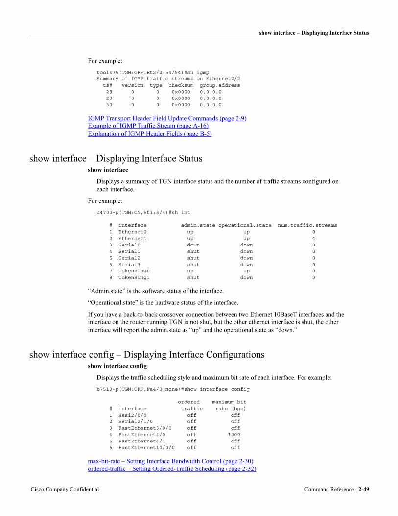
show interface – Displaying Interface Status
For example:
tools75(TGN:OFF,Et2/2:54/54)#sh igmpSummary of IGMP traffic streams on Ethernet2/2 ts# version type checksum group.address 28 0 0 0x0000 0.0.0.0 29 0 0 0x0000 0.0.0.0 30 0 0 0x0000 0.0.0.0
IGMP Transport Header Field Update Commands (page 2-9) Example of IGMP Traffic Stream (page A-16) Explanation of IGMP Header Fields (page B-5)
show interface – Displaying Interface Statusshow interface
Displays a summary of TGN interface status and the number of traffic streams configured on each interface.
For example:
c4700-p(TGN:ON,Et1:3/4)#sh int # interface admin.state operational.state num.traffic.streams 1 Ethernet0 up up 0 2 Ethernet1 up up 4 3 Serial0 down down 0 4 Serial1 shut down 0 5 Serial2 shut down 0 6 Serial3 shut down 0 7 TokenRing0 up up 0 8 TokenRing1 shut down 0
“Admin.state” is the software status of the interface.
“Operational.state” is the hardware status of the interface.
If you have a back-to-back crossover connection between two Ethernet 10BaseT interfaces and the interface on the router running TGN is not shut, but the other ethernet interface is shut, the other interface will report the admin.state as “up” and the operational.state as “down.”
show interface config – Displaying Interface Configurations show interface config
Displays the traffic scheduling style and maximum bit rate of each interface. For example:
b7513-p(TGN:OFF,Fa4/0:none)#show interface config
ordered- maximum bit # interface traffic rate (bps) 1 Hssi2/0/0 off off 2 Serial2/1/0 off off 3 FastEthernet3/0/0 off off 4 FastEthernet4/0 off 1000 5 FastEthernet4/1 off off 6 FastEthernet10/0/0 off off
max-bit-rate – Setting Interface Bandwidth Control (page 2-30) ordered-traffic – Setting Ordered-Traffic Scheduling (page 2-32)
Cisco Company Confidential Command Reference 2-49
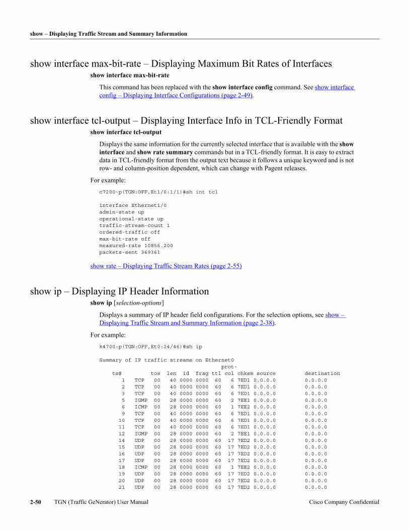
show – Displaying Traffic Stream and Summary Information
show interface max-bit-rate – Displaying Maximum Bit Rates of Interfacesshow interface max-bit-rate
This command has been replaced with the show interface config command. See show interface config – Displaying Interface Configurations (page 2-49).
show interface tcl-output – Displaying Interface Info in TCL-Friendly Formatshow interface tcl-output
Displays the same information for the currently selected interface that is available with the show interface and show rate summary commands but in a TCL-friendly format. It is easy to extract data in TCL-friendly format from the output text because it follows a unique keyword and is not row- and column-position dependent, which can change with Pagent releases.
For example:
c7200-p(TGN:OFF,Et1/0:1/1)#sh int tcl
interface Ethernet1/0admin-state upoperational-state uptraffic-stream-count 1ordered-traffic offmax-bit-rate offmeasured-rate 10856.200packets-sent 369361
show rate – Displaying Traffic Stream Rates (page 2-55)
show ip – Displaying IP Header Informationshow ip [selection-options]
Displays a summary of IP header field configurations. For the selection options, see show – Displaying Traffic Stream and Summary Information (page 2-38).
For example:
k4700-p(TGN:OFF,Et0:24/46)#sh ip
Summary of IP traffic streams on Ethernet0 prot- ts# tos len id frag ttl col chksm source destination 1 TCP 00 40 0000 0000 60 6 7ED1 0.0.0.0 0.0.0.0 2 TCP 00 40 0000 0000 60 6 7ED1 0.0.0.0 0.0.0.0 3 TCP 00 40 0000 0000 60 6 7ED1 0.0.0.0 0.0.0.0 5 IGMP 00 28 0000 0000 60 2 7EE1 0.0.0.0 0.0.0.0 6 ICMP 00 28 0000 0000 60 1 7EE2 0.0.0.0 0.0.0.0 9 TCP 00 40 0000 0000 60 6 7ED1 0.0.0.0 0.0.0.0 10 TCP 00 40 0000 0000 60 6 7ED1 0.0.0.0 0.0.0.0 11 TCP 00 40 0000 0000 60 6 7ED1 0.0.0.0 0.0.0.0 12 IGMP 00 28 0000 0000 60 2 7EE1 0.0.0.0 0.0.0.0 14 UDP 00 28 0000 0000 60 17 7ED2 0.0.0.0 0.0.0.0 15 UDP 00 28 0000 0000 60 17 7ED2 0.0.0.0 0.0.0.0 16 UDP 00 28 0000 0000 60 17 7ED2 0.0.0.0 0.0.0.0 17 UDP 00 28 0000 0000 60 17 7ED2 0.0.0.0 0.0.0.0 18 ICMP 00 28 0000 0000 60 1 7EE2 0.0.0.0 0.0.0.0 19 UDP 00 28 0000 0000 60 17 7ED2 0.0.0.0 0.0.0.0 20 UDP 00 28 0000 0000 60 17 7ED2 0.0.0.0 0.0.0.0 21 UDP 00 28 0000 0000 60 17 7ED2 0.0.0.0 0.0.0.0
TGN (Traffic GeNerator) User Manual Cisco Company Confidential2-50
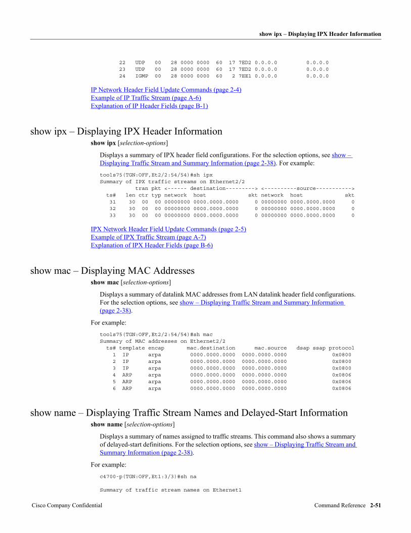
show ipx – Displaying IPX Header Information
22 UDP 00 28 0000 0000 60 17 7ED2 0.0.0.0 0.0.0.0 23 UDP 00 28 0000 0000 60 17 7ED2 0.0.0.0 0.0.0.0 24 IGMP 00 28 0000 0000 60 2 7EE1 0.0.0.0 0.0.0.0
IP Network Header Field Update Commands (page 2-4) Example of IP Traffic Stream (page A-6) Explanation of IP Header Fields (page B-1)
show ipx – Displaying IPX Header Informationshow ipx [selection-options]
Displays a summary of IPX header field configurations. For the selection options, see show – Displaying Traffic Stream and Summary Information (page 2-38). For example:
tools75(TGN:OFF,Et2/2:54/54)#sh ipxSummary of IPX traffic streams on Ethernet2/2 tran pkt <------ destination---------> <----------source-----------> ts# len ctr typ network host skt network host skt 31 30 00 00 00000000 0000.0000.0000 0 00000000 0000.0000.0000 0 32 30 00 00 00000000 0000.0000.0000 0 00000000 0000.0000.0000 0 33 30 00 00 00000000 0000.0000.0000 0 00000000 0000.0000.0000 0
IPX Network Header Field Update Commands (page 2-5) Example of IPX Traffic Stream (page A-7) Explanation of IPX Header Fields (page B-6)
show mac – Displaying MAC Addressesshow mac [selection-options]
Displays a summary of datalink MAC addresses from LAN datalink header field configurations. For the selection options, see show – Displaying Traffic Stream and Summary Information (page 2-38).
For example:
tools75(TGN:OFF,Et2/2:54/54)#sh macSummary of MAC addresses on Ethernet2/2 ts# template encap mac.destination mac.source dsap ssap protocol 1 IP arpa 0000.0000.0000 0000.0000.0000 0x0800 2 IP arpa 0000.0000.0000 0000.0000.0000 0x0800 3 IP arpa 0000.0000.0000 0000.0000.0000 0x0800 4 ARP arpa 0000.0000.0000 0000.0000.0000 0x0806 5 ARP arpa 0000.0000.0000 0000.0000.0000 0x0806 6 ARP arpa 0000.0000.0000 0000.0000.0000 0x0806
show name – Displaying Traffic Stream Names and Delayed-Start Informationshow name [selection-options]
Displays a summary of names assigned to traffic streams. This command also shows a summary of delayed-start definitions. For the selection options, see show – Displaying Traffic Stream and Summary Information (page 2-38).
For example:
c4700-p(TGN:OFF,Et1:3/3)#sh na Summary of traffic stream names on Ethernet1
Cisco Company Confidential Command Reference 2-51
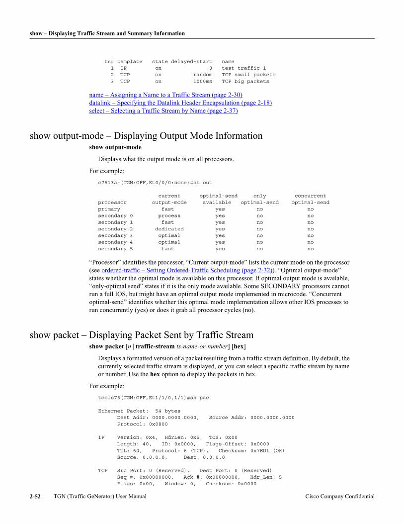
show – Displaying Traffic Stream and Summary Information
ts# template state delayed-start name 1 IP on 0 test traffic 1 2 TCP on random TCP small packets 3 TCP on 1000ms TCP big packets
name – Assigning a Name to a Traffic Stream (page 2-30) datalink – Specifying the Datalink Header Encapsulation (page 2-18) select – Selecting a Traffic Stream by Name (page 2-37)
show output-mode – Displaying Output Mode Informationshow output-mode
Displays what the output mode is on all processors.
For example:
c7513a-(TGN:OFF,Et0/0/0:none)#sh out current optimal-send only concurrentprocessor output-mode available optimal-send optimal-sendprimary fast yes no nosecondary 0 process yes no nosecondary 1 fast yes no nosecondary 2 dedicated yes no nosecondary 3 optimal yes no nosecondary 4 optimal yes no nosecondary 5 fast yes no no
“Processor” identifies the processor. “Current output-mode” lists the current mode on the processor (see ordered-traffic – Setting Ordered-Traffic Scheduling (page 2-32)). “Optimal output-mode” states whether the optimal mode is available on this processor. If optimal output mode is available, “only-optimal send” states if it is the only mode available. Some SECONDARY processors cannot run a full IOS, but might have an optimal output mode implemented in microcode. “Concurrent optimal-send” identifies whether this optimal mode implementation allows other IOS processes to run concurrently (yes) or does it grab all processor cycles (no).
show packet – Displaying Packet Sent by Traffic Streamshow packet [n | traffic-stream ts-name-or-number] [hex]
Displays a formatted version of a packet resulting from a traffic stream definition. By default, the currently selected traffic stream is displayed, or you can select a specific traffic stream by name or number. Use the hex option to display the packets in hex.
For example:
tools75(TGN:OFF,Et1/1/0,1/1)#sh pac Ethernet Packet: 54 bytes Dest Addr: 0000.0000.0000, Source Addr: 0000.0000.0000 Protocol: 0x0800 IP Version: 0x4, HdrLen: 0x5, TOS: 0x00 Length: 40, ID: 0x0000, Flags-Offset: 0x0000 TTL: 60, Protocol: 6 (TCP), Checksum: 0x7ED1 (OK) Source: 0.0.0.0, Dest: 0.0.0.0 TCP Src Port: 0 (Reserved), Dest Port: 0 (Reserved) Seq #: 0x00000000, Ack #: 0x00000000, Hdr_Len: 5 Flags: 0x00, Window: 0, Checksum: 0x0000
TGN (Traffic GeNerator) User Manual Cisco Company Confidential2-52
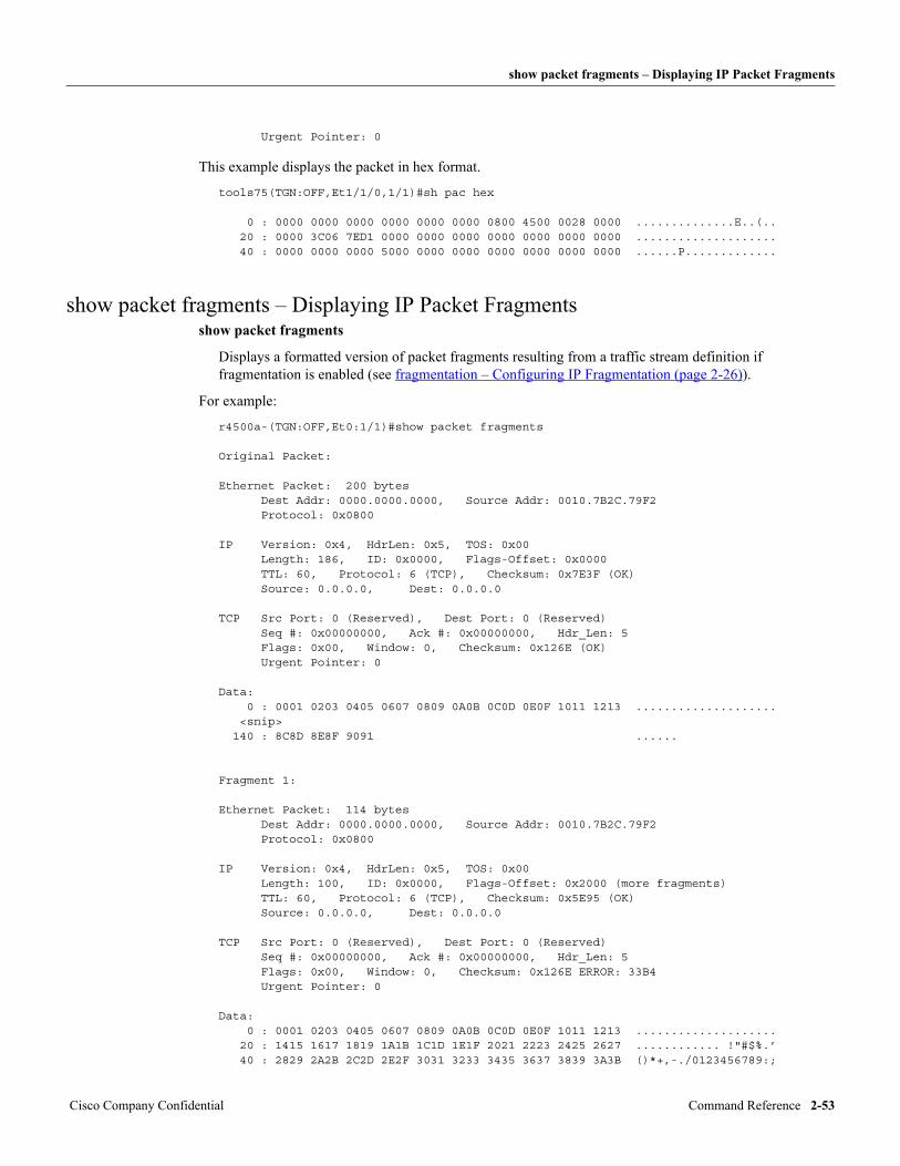
show packet fragments – Displaying IP Packet Fragments
Urgent Pointer: 0
This example displays the packet in hex format.
tools75(TGN:OFF,Et1/1/0,1/1)#sh pac hex 0 : 0000 0000 0000 0000 0000 0000 0800 4500 0028 0000 ..............E..(.. 20 : 0000 3C06 7ED1 0000 0000 0000 0000 0000 0000 0000 .................... 40 : 0000 0000 0000 5000 0000 0000 0000 0000 0000 0000 ......P.............
show packet fragments – Displaying IP Packet Fragmentsshow packet fragments
Displays a formatted version of packet fragments resulting from a traffic stream definition if fragmentation is enabled (see fragmentation – Configuring IP Fragmentation (page 2-26)).
For example:
r4500a-(TGN:OFF,Et0:1/1)#show packet fragments
Original Packet:
Ethernet Packet: 200 bytes Dest Addr: 0000.0000.0000, Source Addr: 0010.7B2C.79F2 Protocol: 0x0800
IP Version: 0x4, HdrLen: 0x5, TOS: 0x00 Length: 186, ID: 0x0000, Flags-Offset: 0x0000 TTL: 60, Protocol: 6 (TCP), Checksum: 0x7E3F (OK) Source: 0.0.0.0, Dest: 0.0.0.0
TCP Src Port: 0 (Reserved), Dest Port: 0 (Reserved) Seq #: 0x00000000, Ack #: 0x00000000, Hdr_Len: 5 Flags: 0x00, Window: 0, Checksum: 0x126E (OK) Urgent Pointer: 0
Data: 0 : 0001 0203 0405 0607 0809 0A0B 0C0D 0E0F 1011 1213 .................... <snip> 140 : 8C8D 8E8F 9091 ......
Fragment 1:
Ethernet Packet: 114 bytes Dest Addr: 0000.0000.0000, Source Addr: 0010.7B2C.79F2 Protocol: 0x0800
IP Version: 0x4, HdrLen: 0x5, TOS: 0x00 Length: 100, ID: 0x0000, Flags-Offset: 0x2000 (more fragments) TTL: 60, Protocol: 6 (TCP), Checksum: 0x5E95 (OK) Source: 0.0.0.0, Dest: 0.0.0.0
TCP Src Port: 0 (Reserved), Dest Port: 0 (Reserved) Seq #: 0x00000000, Ack #: 0x00000000, Hdr_Len: 5 Flags: 0x00, Window: 0, Checksum: 0x126E ERROR: 33B4 Urgent Pointer: 0
Data: 0 : 0001 0203 0405 0607 0809 0A0B 0C0D 0E0F 1011 1213 .................... 20 : 1415 1617 1819 1A1B 1C1D 1E1F 2021 2223 2425 2627 ............ !"#$%.’ 40 : 2829 2A2B 2C2D 2E2F 3031 3233 3435 3637 3839 3A3B ()*+,-./0123456789:;
Cisco Company Confidential Command Reference 2-53
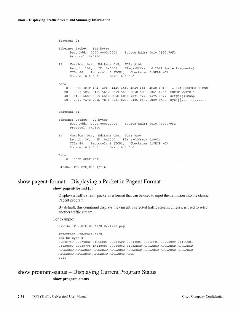
show – Displaying Traffic Stream and Summary Information
Fragment 2:
Ethernet Packet: 114 bytes Dest Addr: 0000.0000.0000, Source Addr: 0010.7B2C.79F2 Protocol: 0x0800
IP Version: 0x4, HdrLen: 0x5, TOS: 0x00 Length: 100, ID: 0x0000, Flags-Offset: 0x200A (more fragments) TTL: 60, Protocol: 6 (TCP), Checksum: 0x5E8B (OK) Source: 0.0.0.0, Dest: 0.0.0.0
Data: 0 : 3C3D 3E3F 4041 4243 4445 4647 4849 4A4B 4C4D 4E4F .=.?@ABCDEFGHIJKLMNO 20 : 5051 5253 5455 5657 5859 5A5B 5C5D 5E5F 6061 6263 PQRSTUVWXYZ[\ 40 : 6465 6667 6869 6A6B 6C6D 6E6F 7071 7273 7475 7677 defghijklmnop 60 : 7879 7A7B 7C7D 7E7F 8081 8283 8485 8687 8889 8A8B xyz{|}..............
Fragment 3: Ethernet Packet: 40 bytes Dest Addr: 0000.0000.0000, Source Addr: 0010.7B2C.79F2 Protocol: 0x0800
IP Version: 0x4, HdrLen: 0x5, TOS: 0x00 Length: 26, ID: 0x0000, Flags-Offset: 0x0014 TTL: 60, Protocol: 6 (TCP), Checksum: 0x7ECB (OK) Source: 0.0.0.0, Dest: 0.0.0.0
Data: 0 : 8C8D 8E8F 9091 ......
r4500a-(TGN:OFF,Et0:1/1)#
show pagent-format – Displaying a Packet in Pagent Formatshow pagent-format [n]
Displays a traffic stream packet in a format that can be used to input the definition into the classic Pagent program.
By default, this command displays the currently selected traffic stream, unless n is used to select another traffic stream.
For example:
c7513a-(TGN:OFF,Et0/0/0:2/2)#sh pag interface Ethernet0/0/0add $$ byte 000E0F759 E50700E0 34C5E800 08004500 00640001 0000FF01 79758009 0116C001 01020800 6B630798 1A440000 00000002 F108ABCD ABCDABCD ABCDABCD ABCDABCD ABCDABCD ABCDABCD ABCDABCD ABCDABCD ABCDABCD ABCDABCD ABCDABCD ABCDABCD ABCDABCD ABCDABCD ABCDABCD ABCDABCD ABCDquit
show program-status – Displaying Current Program Statusshow program-status
TGN (Traffic GeNerator) User Manual Cisco Company Confidential2-54
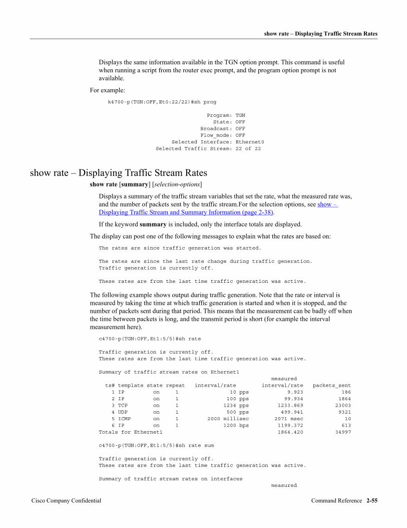
show rate – Displaying Traffic Stream Rates
Displays the same information available in the TGN option prompt. This command is useful when running a script from the router exec prompt, and the program option prompt is not available.
For example:
k4700-p(TGN:OFF,Et0:22/22)#sh prog
Program: TGN State: OFF Broadcast: OFF Flow_mode: OFF Selected Interface: Ethernet0 Selected Traffic Stream: 22 of 22
show rate – Displaying Traffic Stream Ratesshow rate [summary] [selection-options]
Displays a summary of the traffic stream variables that set the rate, what the measured rate was, and the number of packets sent by the traffic stream.For the selection options, see show – Displaying Traffic Stream and Summary Information (page 2-38).
If the keyword summary is included, only the interface totals are displayed.
The display can post one of the following messages to explain what the rates are based on:
The rates are since traffic generation was started. The rates are since the last rate change during traffic generation.Traffic generation is currently off.
These rates are from the last time traffic generation was active.
The following example shows output during traffic generation. Note that the rate or interval is measured by taking the time at which traffic generation is started and when it is stopped, and the number of packets sent during that period. This means that the measurement can be badly off when the time between packets is long, and the transmit period is short (for example the interval measurement here).
c4700-p(TGN:OFF,Et1:5/5)#sh rate Traffic generation is currently off.These rates are from the last time traffic generation was active.
Summary of traffic stream rates on Ethernet1 measured ts# template state repeat interval/rate interval/rate packets_sent 1 IP on 1 10 pps 9.923 186 2 IP on 1 100 pps 99.934 1864 3 TCP on 1 1234 pps 1233.869 23003 4 UDP on 1 500 pps 499.941 9321 5 ICMP on 1 2000 millisec 2071 msec 10 6 IP on 1 1200 bps 1199.372 613Totals for Ethernet1 1864.420 34997 c4700-p(TGN:OFF,Et1:5/5)#sh rate sum Traffic generation is currently off.These rates are from the last time traffic generation was active. Summary of traffic stream rates on interfaces measured
Cisco Company Confidential Command Reference 2-55
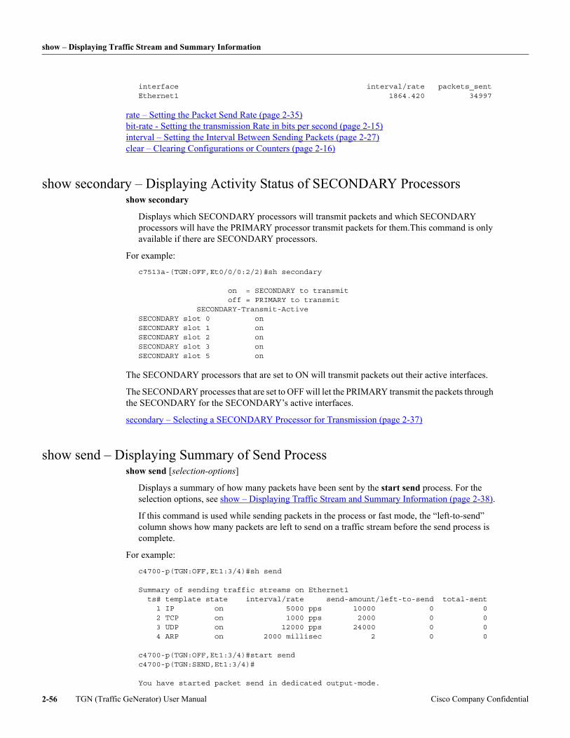
show – Displaying Traffic Stream and Summary Information
interface interval/rate packets_sentEthernet1 1864.420 34997
rate – Setting the Packet Send Rate (page 2-35) bit-rate - Setting the transmission Rate in bits per second (page 2-15) interval – Setting the Interval Between Sending Packets (page 2-27) clear – Clearing Configurations or Counters (page 2-16)
show secondary – Displaying Activity Status of SECONDARY Processorsshow secondary
Displays which SECONDARY processors will transmit packets and which SECONDARY processors will have the PRIMARY processor transmit packets for them.This command is only available if there are SECONDARY processors.
For example:
c7513a-(TGN:OFF,Et0/0/0:2/2)#sh secondary on = SECONDARY to transmit off = PRIMARY to transmit SECONDARY-Transmit-ActiveSECONDARY slot 0 onSECONDARY slot 1 onSECONDARY slot 2 onSECONDARY slot 3 onSECONDARY slot 5 on
The SECONDARY processors that are set to ON will transmit packets out their active interfaces.
The SECONDARY processes that are set to OFF will let the PRIMARY transmit the packets through the SECONDARY for the SECONDARY’s active interfaces.
secondary – Selecting a SECONDARY Processor for Transmission (page 2-37)
show send – Displaying Summary of Send Processshow send [selection-options]
Displays a summary of how many packets have been sent by the start send process. For the selection options, see show – Displaying Traffic Stream and Summary Information (page 2-38).
If this command is used while sending packets in the process or fast mode, the “left-to-send” column shows how many packets are left to send on a traffic stream before the send process is complete.
For example:
c4700-p(TGN:OFF,Et1:3/4)#sh send Summary of sending traffic streams on Ethernet1 ts# template state interval/rate send-amount/left-to-send total-sent 1 IP on 5000 pps 10000 0 0 2 TCP on 1000 pps 2000 0 0 3 UDP on 12000 pps 24000 0 0 4 ARP on 2000 millisec 2 0 0 c4700-p(TGN:OFF,Et1:3/4)#start sendc4700-p(TGN:SEND,Et1:3/4)# You have started packet send in dedicated output-mode.
TGN (Traffic GeNerator) User Manual Cisco Company Confidential2-56
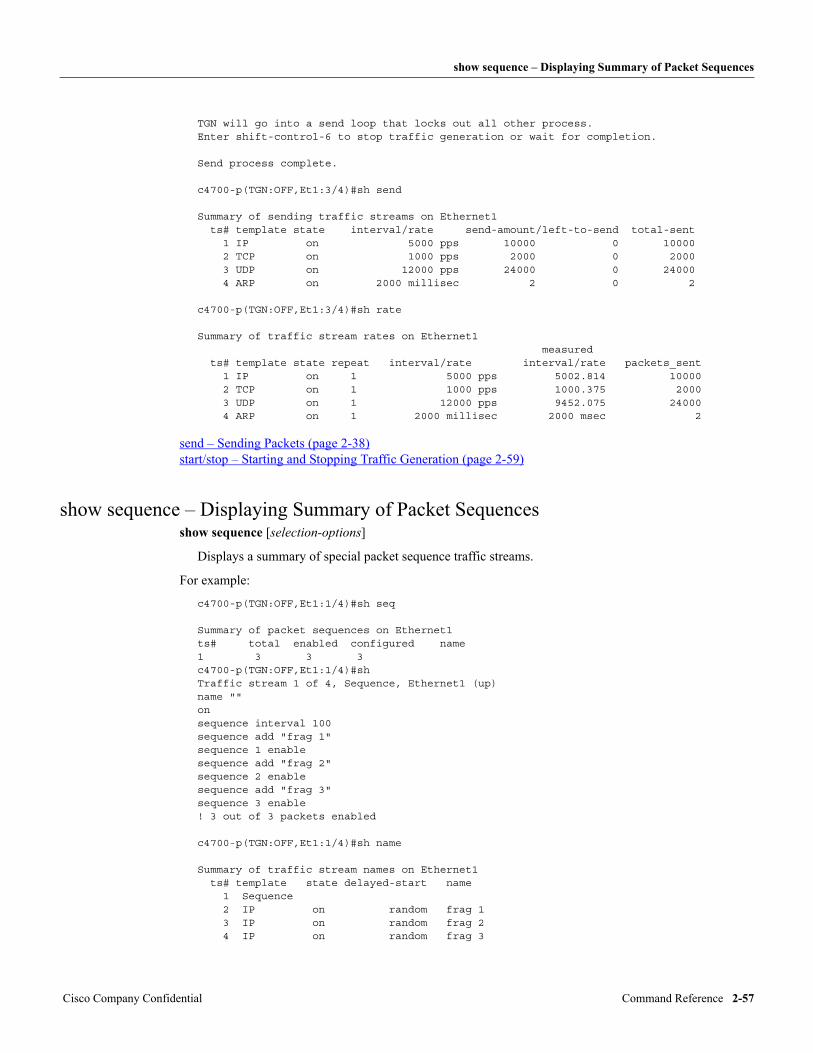
show sequence – Displaying Summary of Packet Sequences
TGN will go into a send loop that locks out all other process.Enter shift-control-6 to stop traffic generation or wait for completion. Send process complete. c4700-p(TGN:OFF,Et1:3/4)#sh send Summary of sending traffic streams on Ethernet1 ts# template state interval/rate send-amount/left-to-send total-sent 1 IP on 5000 pps 10000 0 10000 2 TCP on 1000 pps 2000 0 2000 3 UDP on 12000 pps 24000 0 24000 4 ARP on 2000 millisec 2 0 2 c4700-p(TGN:OFF,Et1:3/4)#sh rate Summary of traffic stream rates on Ethernet1 measured ts# template state repeat interval/rate interval/rate packets_sent 1 IP on 1 5000 pps 5002.814 10000 2 TCP on 1 1000 pps 1000.375 2000 3 UDP on 1 12000 pps 9452.075 24000 4 ARP on 1 2000 millisec 2000 msec 2
send – Sending Packets (page 2-38) start/stop – Starting and Stopping Traffic Generation (page 2-59)
show sequence – Displaying Summary of Packet Sequencesshow sequence [selection-options]
Displays a summary of special packet sequence traffic streams.
For example:
c4700-p(TGN:OFF,Et1:1/4)#sh seq
Summary of packet sequences on Ethernet1ts# total enabled configured name1 3 3 3c4700-p(TGN:OFF,Et1:1/4)#shTraffic stream 1 of 4, Sequence, Ethernet1 (up)name ""onsequence interval 100sequence add "frag 1"sequence 1 enablesequence add "frag 2"sequence 2 enablesequence add "frag 3"sequence 3 enable! 3 out of 3 packets enabled
c4700-p(TGN:OFF,Et1:1/4)#sh name
Summary of traffic stream names on Ethernet1 ts# template state delayed-start name 1 Sequence 2 IP on random frag 1 3 IP on random frag 2 4 IP on random frag 3
Cisco Company Confidential Command Reference 2-57
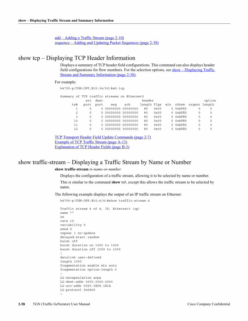
show – Displaying Traffic Stream and Summary Information
add – Adding a Traffic Stream (page 2-10) sequence – Adding and Updating Packet Sequences (page 2-38)
show tcp – Displaying TCP Header InformationDisplays a summary of TCP header field configurations. This command can also displays header field configurations for flow members. For the selection options, see show – Displaying Traffic Stream and Summary Information (page 2-38).
For example: k4700-p(TGN:OFF,Et0:34/50)#sh tcp
Summary of TCP traffic streams on Ethernet0 src dest header option ts# port port seq ack length flgs win chksm urgent length 1 0 0 00000000 00000000 80 0x00 0 0xAFE5 0 0 2 0 0 00000000 00000000 80 0x00 0 0xAFE5 0 0 3 0 0 00000000 00000000 80 0x00 0 0xAFE5 0 0 10 0 0 00000000 00000000 80 0x00 0 0xAFE5 0 0 11 0 0 00000000 00000000 80 0x00 0 0xAFE5 0 0 12 0 0 00000000 00000000 80 0x00 0 0xAFE5 0 0
TCP Transport Header Field Update Commands (page 2-7) Example of TCP Traffic Stream (page A-13) Explanation of TCP Header Fields (page B-3)
show traffic-stream – Displaying a Traffic Stream by Name or Numbershow traffic-stream ts-name-or-number
Displays the configuration of a traffic stream, allowing it to be selected by name or number. This is similar to the command show ts#, except this allows the traffic stream to be selected by name.
The following example displays the output of an IP traffic stream on Ethernet: k4700-p(TGN:OFF,Et0:4/4)#show traffic-stream 4
Traffic stream 4 of 4, IP, Ethernet0 (up)name ""onrate 10variability 0send 0repeat 1 no-updatedelayed-start randomburst offburst duration on 1000 to 1000burst duration off 1000 to 1000!datalink user-definedlength 1000fragmentation enable mtu autofragmentation option-length 0!L2-encapsulation arpaL2-dest-addr 0000.0000.0000L2-src-addr 0060.3E58.1E1AL2-protocol 0x0800!
TGN (Traffic GeNerator) User Manual Cisco Company Confidential2-58
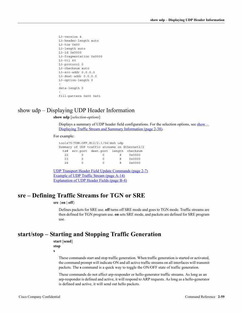
show udp – Displaying UDP Header Information
L3-version 4L3-header-length autoL3-tos 0x00L3-length autoL3-id 0x0000L3-fragmentation 0x0000L3-ttl 60L3-protocol 0L3-checksum autoL3-src-addr 0.0.0.0L3-dest-addr 0.0.0.0L3-option-length 0!data-length 0!fill-pattern 0x00 0x01
show udp – Displaying UDP Header Informationshow udp [selection-options]
Displays a summary of UDP header field configurations. For the selection options, see show – Displaying Traffic Stream and Summary Information (page 2-38).
For example:
tools75(TGN:OFF,Et2/2:1/54)#sh udpSummary of UDP traffic streams on Ethernet2/2 ts# src.port dest.port length checksum 22 0 0 8 0x0000 23 0 0 8 0x0000 24 0 0 8 0x0000
UDP Transport Header Field Update Commands (page 2-7) Example of UDP Traffic Stream (page A-14) Explanation of UDP Header Fields (page B-4)
sre – Defining Traffic Streams for TGN or SREsre {on | off}
Defines packets for SRE use. off turns off SRE mode and goes to TGN mode. Traffic streams are then defined for TGN program use. on sets SRE mode, and packets are defined for SRE program use.
start/stop – Starting and Stopping Traffic Generationstart [send] stop s
These commands start and stop traffic generation. When traffic generation is started or activated, the command prompt will indicate ON and all active traffic streams on all interfaces will transmit packets. The s command is a quick way to toggle the ON/OFF state of traffic generation.
These commands do not affect arp-responder or hello-generator traffic streams. As long as an arp-responder is defined and active, it will respond to ARP requests. As long as a hello-generator is defined and active, it will send out hello packets.
Cisco Company Confidential Command Reference 2-59
variability – Defining the Variability in Packet Intervals
The start command has two modes.
start
Starts traffic generation. Traffic does not stop until the stop command (or cntrl-shift-6 for dedicated mode) is entered.
start send
Causes only traffic streams that have a “send count” entered to send packets until the requested number of packets are sent for the traffic stream. When all traffic streams have sent their packets, the program posts the message “Send Complete” and stops traffic generation.
This send mode can also be aborted with the stop command.
variability – Defining the Variability in Packet Intervalsvariability percent
Defines the variability, from 0 to 100 percent, in the time interval between packets.
By default, percent is 0, that is, there is a constant time interval between each packet sent by a traffic stream.
If percent is not zero, it defines a range of interval values, plus and minus from the interval defined by the rate or interval or bit-rate command. A new and different interval is calculated within this range after each packet.
For example, assume a 10 pps traffic stream:
• If variability is 0 percent, the interval between packets is 100 milliseconds.
• If variability is 50 percent, intervals are random, from 50 to 150 milliseconds.
• At maximum variability of 100 percent, the intervals are random from 0 to 200 milliseconds.
In all cases, the average rate over a period of time is equal to the rate set by the rate or interval or bit-rate command, even though individual intervals would vary.
This does not affect the interval between packets sent in a repeat, which are still sent as fast as possible. Instead, it affects the time interval between the repeat sends (see repeat – Resending Packets Repeatedly (page 2-35)).
rate – Setting the Packet Send Rate (page 2-35) bit-rate - Setting the transmission Rate in bits per second (page 2-15)
verbose - Configuring for Activity Messagesverbose {off | on} verbose logging-to {ios-logging | console}
These commands are global across all processes.
verbose {off | on}
Determines whether the start and stop commands generate activity messages. The default is off.
verbose logging-to {ios-logging | console}
Determines where the activity messages will be posted. The default is to display the messages on the console.
TGN (Traffic GeNerator) User Manual Cisco Company Confidential2-60
wait-to-release – Sierra Wait-to-Release Paktype
If this is set for ios-logging, the activity messages are passed to the IOS logging facility as level 6 (informational) messages. Depending on how IOS logging is configured, these messages can have timestamps added and be posted to the console and/or log file and/or system log. For more information on how to configure IOS logging, see the logging commands in the Cisco IOS Configuration Fundamentals Command Reference -> Cisco IOS System Management Commands -> Troubleshooting Commands.
wait-to-release – Sierra Wait-to-Release Paktypewait-to-release n
This command is only available on the sierra routers (4500 and 4700). It helps get around a problem of releasing paktypes at fast output rates.
By default, this value is set to 0, that is, in fast and dedicated output modes, paktypes are released immediately. In some situations, at fast output rates, paktypes might not get released and might result in a slow memory leak.
If the memory leak is a problem, set a wait-to-release time of n seconds. This causes a wait period of n seconds after a stop command before the paktypes are forced to be released by setting their refcount. If you set wait time too short, IOS complains with “incorrect refcount” error messages, so you will have to increase the wait time.
In most cases, a wait time of 1 second is enough. In some situations, 10 seconds might not be enough.
The wait period is reflected in the command prompt options. The program prevents restarting traffic generation until the wait period is over.
write – Writing Information to an IFS Log Filewrite ....
Commands that start with the keyword show are used to display information on the console. For every show command, there is an equivalent write command that displays the same information on the console but also writes it to an opened IFS log file.
IOS File System (page 1-10) show – Displaying Traffic Stream and Summary Information (page 2-38) open-logfile – Opening an IFS Log File (page 2-31)
close-logfile – Closing an Open IFS Log File (page 2-17)
Cisco Company Confidential Command Reference 2-61

write – Writing Information to an IFS Log File
TGN (Traffic GeNerator) User Manual Cisco Company Confidential2-62
C H A P T E R
Cisco Company Confidential Defining Header Field Value
3
Defining Header Field Values
Almost all header fields have decimal, hex, mac address, or IP address field data. These can all be defined as having a constant value, incrementing or being random over a range.
A few fields are defined by entering a string of hex numbers. These fields cannot be incrementing or random, although it is possible to lay a configurable field on top of these fields to add variability. These fields include the Token Ring Routing Information Field (RIF), Connectionless Network Service (CLNS) source and destination areas, IP option field, and TCP option field.
Checksum and header length fields also have the additional ability of being defined automatically to accommodate changing packet lengths and data.
Decimal and Hex FieldsMost header fields are decimal or hexadecimal numbers, 1 to 4 bytes in length. There are three command formats to define these fields.
In the following, “Ln....” represents an L2-... command to define a datalink header field, an L3-...command to define a network header field, or an L4-... command to define a transport header field.
All of these values can be entered as decimal or hex. Hex numbers must start with 0x.
Ln-... value
Sets the field to a constant value.
The generic prompt for these numbers always prompts for a number that is valid for a 4 byte field. If the number entered is too large, an error message indicates the correct maximum value.
For example:
tools75(TGN:OFF,Et0/0/0,1/3)#l3-ttl 1000*** The value exceeds field size of 0xFF (255).
Ln-... increment min-value to max-value [by inc-by]
Causes the field value to increment from min-value to max-value with each packet sent. By default, it increments by 1 byte to max-value and restarts at min-value. The inc-by option allows the field value to increase by the inc-by] byte amount instead of by 1.
Ln-... random min-value to max-value [by inc-by]
Causes the field value to be random from min-value to max-value. By default, the random value can be from min-value to max-value. The inc-by option causes the field value to be min-value plus multiples of inc-by, instead of multiples of 1.
s 3-1
MAC Address Fields
The following are examples of setting hex and decimal fields:
L3-protocol 10
L3-ttl increment 20 to 50
L3-tos increment 20 to 100 by 5
L4-seq random 0x10000 to 0x20000
L4-ack random 0x10000 to 0x20000 by 0x100
Nested Increments (page 3-3)
MAC Address FieldsLn-... value Ln-... increment min-value to max-value [by inc-by] Ln-... random min-value to max-value [by inc-by]
Fields with MAC addresses are entered just like the decimal and hex values defined in Decimal and Hex Fields (page 3-1), except that all values are entered as full MAC addresses, except for the inc-by, which is entered as max 4 byte decimal or hex value.
The increment and random options only affect the last 4 bytes of these 6 byte fields. If you need to have the first 2 bytes changing, lay a configurable field on top of these bytes.
The following are examples of setting MAC address fields:
L2-dest-addr 0000.0c98.a44c
L2-src-addr increment 00ab.0004.0000 to 00ab.0004.1000
L2-src-addr increment 0000.0000.abcd to 0000.0100.abcd by 0x10000
L3-dest-host random 0011.2222.0000 to 0011.2222.3000
L3-src-host random 0000.1111.0000 to 0000.1111.5500 by 0x100
Nested Increments (page 3-3)
IP Address FieldsLn-... value Ln-... increment min-value to max-value [by inc-by] [subnet subnet-mask] Ln-... random min-value to max-value [by inc-by] [subnet subnet-mask]
Fields with IP addresses are entered just like the decimal and hex values defined in Decimal and Hex Fields (page 3-1), except that all values are entered as full IP addresses, including the inc-by value.
It can include a subnet mask, so subnet broadcast addresses are not generated.
The following are examples of setting IP address fields:
L3-src-addr 100.1.1.1
L3-dest-addr increment 1.1.1.1 to 1.1.1.255
L3-dest-addr increment 1.1.1.1 to 1.1.255.1 by 0.0.1.0
L3-dest-addr random 192.1.1.1 to 192.1.255.255
L3-src-addr random 192.1.1.1 to 192.1.1.255 by 0.0.0.5
TGN (Traffic GeNerator) User Manual Cisco Company Confidential3-2
IPv6 Address Fields
If you need to generate a wide range of IP addresses that span several subnets, you probably do not want to send subnet broadcast packets. If you configure a subnet mask for incrementing and random IP addresses, the TGN program will not generate addresses where the subnet address bits are all zeros or all ones.
The following is a repeat of the above examples with subnet masks added:
L3-dest-addr increment 1.1.1.1 to 1.1.1.255 subnet 255.255.255.0
L3-dest-addr increment 1.1.1.1 to 1.1.255.1 by 0.0.1.0 subnet 255.255.128.0
L3-dest-addr random 192.1.1.1 to 192.1.255.255 subnet 255.255.255.240
L3-src-addr random 192.1.1.1 to 192.1.1.255 by 0.0.0.5 subnet 255.255.255.192
Nested Increments (page 3-3)
IPv6 Address FieldsLn-... value
IPv6 address do not directly support incrementing or random values.
For reasons of performance, incrementing and random fields are limited to a 32-bit CPU word, 4 bytes. Four bytes is big enough to hold an entire IPv4 address or the last 4 bytes of a MAC address, but an IPv6 address is 16 bytes long. This problem is solved by using the configurable field option. With this you can lay an incrementing or random field up to 4 bytes long on the appropriate bytes of an IPv6 address.
Example 1:
To increment the last 4 bytes of the IPv6 source address in an IPv6 header, from 1 to 1000:
field add incr_src_ipv6field start-at network-start offset 20field type 4 decimalfield data increment 1 to 1000
Note that the incrementing or random field is identified by the number of bytes from the start of the header. In the IPv6 header, the source address starts 8 from the start of the header.
The last four bytes of the 16-byte IPv6 source address (bytes 13 to 16) start 8 + 12 bytes from the start of the network header.
Example 2:
To make the seventh and eighth bytes of the destination IPv6 address random from 0 to 0xFFFF:
field add rand_dest_ipv6field start-at network-start offset 30field type 2 hexfield data random 0 to 0xFFFF
In the IPv6 header, the destination address starts 24 bytes from the start of the header, so the seventh byte in the address starts 24 + 6 = 30 bytes from the start of the header.
Nested IncrementsAny header field that can be set to increment over a range also has the ability to be linked to another incrementing field. This is the nest-over option and looks like this:
... increment min to max [nest-over field-name]
Cisco Company Confidential Defining Header Field Values 3-3
Automatic Setting of Length and Checksum Fields
With this option, the incrementing field increments only when the incrementing field it points to wraps from its max to min value. This allows the traffic stream to step through all possible combinations of the two fields.
The field-name can be any L2-, L3-, L4-, or configurable field name, but it must adhere to the following rules:
• Entered correctly in full
• Valid within the template
• Set to increment before traffic generation or expand
Nested incrementing fields can nest several deep, and several incrementing fields can nest to a single incrementing field.
An incrementing packet length can be set to nest-over an incrementing header field, and incrementing header fields can be set to nest-over length. This is an exception, because packet length is not a header field.
In this example, every time the IP destination address increments through its range of addresses, the IP source address increments by 1.
L3-src-addr increment 22.1.1.1 to 22.1.1.10 nest-over L3-dest-addrL3-dest-addr increment 100.1.1.1 to 100.1.1.100
Automatic Setting of Length and Checksum FieldsMost header length and several header checksum fields have the additional ability to be set automatically to a correct value.
When these fields are initially defined, these fields default to auto. This allows packets to be defined and updated with incrementing and random values or with incrementing or random lengths. The length and checksum fields are updated automatically to the correct value.
The same is true for checksums in the IP, TCP, UDP, ICMP, and IGMP headers.
The calculated length values and checksum are what is required for a router to accept and forward a packet.
These length and checksum fields can be set to user-defined constant, incrementing, or random values, but the only reason to do so is to introduce invalid data into a packet for negative testing.
Token Ring RIFThe Token Ring RIF field is unlike other header fields. It may or may not exist in the datalink header, and if it exists, it is of variable length up to 32 bytes long.
The default RIF field length is 0. This field is entered as a series of hex bytes. A valid RIF field has an even number of bytes, but TGN allows a field length of an odd number of bytes for testing purposes.
In the second byte of the RIF field is a field that indicates the RIF field length. The program forces the correct RIF length into this field. An incorrect length trashes the rest of the packet.
The RIF field cannot be set to be incrementing or random. If you need variability in this field, lay an configurable field on top of the RIF field.
The following is an example of a RIF field entry:
L2-rif C006 0021 0030
TGN (Traffic GeNerator) User Manual Cisco Company Confidential3-4
CLNS Area Fields
CLNS Area FieldsIn the CLNS header, the source and destination area fields are variable length fields up to 13 bytes long. These fields are entered as a series of hex bytes. A valid area is an odd number of bytes long.
The CLNS area fields cannot be set to be incrementing or random. If you need variability in these fields, lay a configurable field on top.
The following are examples of CLNS area fields:
L3-dest-area 47.0010.aa01.00ccL3-src-area 47.0102.0304.0506.0708.0910.1112
Cisco Company Confidential Defining Header Field Values 3-5

CLNS Area Fields
TGN (Traffic GeNerator) User Manual Cisco Company Confidential3-6
C H A P T E R
Cisco Company Confidential ARP-Responder and Hello-Generator Command
4
ARP-Responder and Hello-Generator Commands
The ARP-responder and hello-generator commands configure the ARP responders and hello-generators.
The purpose of these responders and generators is to make the router think there is a live end station waiting to receive packets to the specific network address. The hello-generators tell the router which interface the end station is on, and all of these tell the router the MAC address of the end station.
IP ARP ResponderThe IP ARP Responder responds to ARP requests for one IP address or a range of them.
The ARP Responder is typically used to act as a fictitious end station. If you are using a traffic generator (like TGN) to send packets to a non-existent end station or IP address, you need the ARP responder to act as the end station so that the router forwards the test packets on the destination network.
If the ARP responder is not used and the end-station IP address has not been statically configured in the ARP cache, the router sends out an ARP request for each test packet. After timeout, it sends an ICMP “host unreachable” message back to the source IP address.
With the ARP responder, the first test packet results in an ARP request. The ARP responder sends a reply giving a MAC address to which the router can forward packets. With the destination address now in the router’s ARP cache, all subsequent packets to that IP address are forwarded immediately.
To create the ARP Responder, first use the add arp responder command (see add – Adding a Traffic Stream (page 2-10)). Similar to regular traffic streams, multiple ARP responders can be created on each interface.
Use one of the following commands to define which IP address or range of IP addresses the ARP responder will respond to:
ip-address a.b.c.d ip-address a.b.c.d to a.b.c.d
The following is the fictitious MAC address in the ARP response. It can be any MAC address. It is not related to the bia address of the interface (though in most cases, you configure it to be the MAC address of the interface). If the ARP responder is to respond to a range of IP addresses, you can configure it to respond with a constant MAC address for all the IP addresses in the range or with an equal range of MAC addresses starting with this configured MAC address:
mac-address hhhh.hhhh.hhhh [constant]
The following activates or deactivates the ARP responder: on | off
s 4-1
AppleTalk ARP Responder
Example of IP ARP Responder (page A-21) show arp-responder – Displaying ARP Responders (page 2-43)
AppleTalk ARP ResponderTo create the Appletalk ARP (AARP) Responder, first use the add aarp responder command (see add – Adding a Traffic Stream (page 2-10)).
Use one of the following commands to define which AppleTalk address or range of AppleTalk addresses the AARP responder will respond to:
appletalk-address net.node appletalk-address net.node to net.node
The following is the fictitious MAC address in the AARP response. If the AARP responder is to respond to a range of AppleTalk addresses, it responds with an equal range of MAC addresses starting with this configured MAC address:
mac-address hhhh.hhhh.hhhh
The following activates or deactivates the AARP responder:
on | off
Example of AARP (AppleTalk ARP) Responder (page A-21) show aarp-responder – Displaying AARP Responders (page 2-41)
VINES Hello-GeneratorTo create the VINES hello-generator, first use the add vines hello-generator command (see add – Adding a Traffic Stream (page 2-10)). The following commands configure the VINES hello-generator.
hello-address network:subnet
VINES address the hello-generator advertises as an active end station.
mac-address hhhh.hhhh.hhhh
Fictitious MAC address the router is to send the packets to.
on | off
Activates or deactivates the VINES hello-generator.
Example of VINES Hello-Generator (page A-21) sre – Defining Traffic Streams for TGN or SRE (page 2-59)
CLNS Hello-GeneratorTo create the CLNS hello-generator, first use the add clns hello-generator command (see add – Adding a Traffic Stream (page 2-10)). The following commands configure the CLNS hello-generator.
hello-address 47.0000.0000.0000.0011.2222.3333.00
CLNS address the hello-generator advertises as an active end station. It shows the command with an example CLNS address. The MAC address is extracted from the CLNS address. In this example, the MAC address is 0011.2222.3333.
on | off
TGN (Traffic GeNerator) User Manual Cisco Company Confidential4-2
DECnet Hello-Generator
Activates or deactivates the CLNS hello-generator.
Example of CLNS Hello-Generator (page A-21) show clns-hello-generator – Displaying CLNS Hello-generators (page 2-45)
DECnet Hello-GeneratorTo create the CLNS hello-generator, first use the add decnet hello-generator command (see add – Adding a Traffic Stream (page 2-10)). The following commands configure the DECnet hello-generator.
hello-address area.node
DECnet address the hello-generator advertises as an active end station. In the DECnet protocol, the area node address defines the MAC address.
designated-router area.node
The DECnet end station hello packet includes a field that identifies the designated router the end station sends its packets to.
on | off
Activates or deactivates the DECnet hello-generator.
Example of DECnet Hello-Generator (page A-21) show decnet-hello – Displaying DECnet Hello-Generators (page 2-46)
Cisco Company Confidential ARP-Responder and Hello-Generator Commands 4-3

DECnet Hello-Generator
TGN (Traffic GeNerator) User Manual Cisco Company Confidential4-4
C H A P T E R
Cisco Company Confidential Using TGN and PKTS Timestamps to Measure Latenc
5
Using TGN and PKTS Timestamps to Measure Latency
The timestamp configurable field is included in TGN and PKTS to help measure latency through a network.
When the timestamp field is configured on a TGN traffic stream, TGN puts a timestamp in the packet just before sending it. This occurs before any transport checksums are calculated, so that the timestamp can be added into a valid TCP or UDP packet. Turn off transport checksumming if the checksum is not important to the test.
When the timestamp field is configured in a PKTS filter, PKTS can extract the timestamp from the packet and compare it to the time it received the packet. The show timestamp command can be used to display the time difference.
It is important that the same router is used to send and receive, so that both the send and receive timestamps come from the same timebase.
Creating a TGN Traffic Stream with a TimestampThe easiest way to add a timestamp configurable field to a TGN traffic stream is to add the timestamp keyword when the traffic stream is created. This puts the 8 byte timestamp in the first 8 bytes of the data array.
For example:
add ip timestamp
Creating a PKTS Selective Filter with a TimestampThe easiest way to add a timestamp configurable field to a PKTS filter is to add the timestamp keyword when the filter is created. This defines the timestamp to be in the first 8 bytes of the data array, and it sets this to be a display filter of incoming packets.
In PKTS FILTER mode, do the following:
add ip timestamp
Displaying Timestamp InformationTo display timestamp information, use the show timestamp command:
show timestamp [command-line-filter-options] [stats-only]
This command only display packets that match a display filter with a configurable timestamp field. All the usual command line filter options are available to select a subset of the packets.
y 5-1
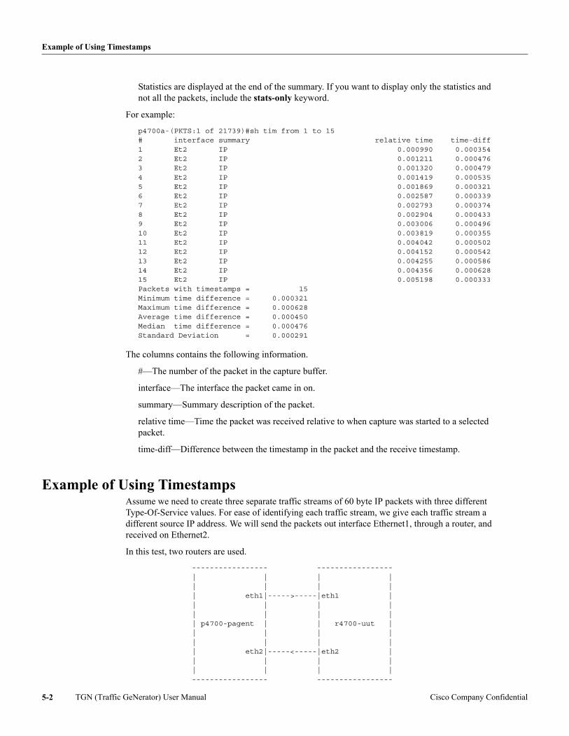
Example of Using Timestamps
Statistics are displayed at the end of the summary. If you want to display only the statistics and not all the packets, include the stats-only keyword.
For example:
p4700a-(PKTS:1 of 21739)#sh tim from 1 to 15# interface summary relative time time-diff1 Et2 IP 0.000990 0.0003542 Et2 IP 0.001211 0.0004763 Et2 IP 0.001320 0.0004794 Et2 IP 0.001419 0.0005355 Et2 IP 0.001869 0.0003216 Et2 IP 0.002587 0.0003397 Et2 IP 0.002793 0.0003748 Et2 IP 0.002904 0.0004339 Et2 IP 0.003006 0.00049610 Et2 IP 0.003819 0.00035511 Et2 IP 0.004042 0.00050212 Et2 IP 0.004152 0.00054213 Et2 IP 0.004255 0.00058614 Et2 IP 0.004356 0.00062815 Et2 IP 0.005198 0.000333Packets with timestamps = 15Minimum time difference = 0.000321Maximum time difference = 0.000628Average time difference = 0.000450Median time difference = 0.000476Standard Deviation = 0.000291
The columns contains the following information.
#—The number of the packet in the capture buffer.
interface—The interface the packet came in on.
summary—Summary description of the packet.
relative time—Time the packet was received relative to when capture was started to a selected packet.
time-diff—Difference between the timestamp in the packet and the receive timestamp.
Example of Using TimestampsAssume we need to create three separate traffic streams of 60 byte IP packets with three different Type-Of-Service values. For ease of identifying each traffic stream, we give each traffic stream a different source IP address. We will send the packets out interface Ethernet1, through a router, and received on Ethernet2.
In this test, two routers are used.
----------------- ----------------- | | | | | | | | | eth1|----->-----|eth1 | | | | | | | | | | p4700-pagent | | r4700-uut | | | | | | | | | | eth2|-----<-----|eth2 | | | | | | | | | ----------------- -----------------
TGN (Traffic GeNerator) User Manual Cisco Company Confidential5-2
Example of Using Timestamps
Router p4700-pagent is used to run TGN and PKTS:
1 TGN will send packets out interface ethernet1.
2 PKTS will capture packets on interface ethernet2.
Router r4700-uut is used to run the IOS image under test.
The two routers are connected back to back, ethernet1 to ethernet1, ethernet2 to ethernet2.
We enter the following configurations on the two routers and make sure all four interfaces are not shut.
On the r4700-uut, this configures the router we are sending packets through:
interface eth1 ip address 1.1.1.10 255.255.255.0 mac-address 0000.1111.1111 no shut interface eth2 ip address 1.1.2.10 255.255.255.0 no shut router igrp 2 network 1.0.0.0
On the router running Pagent, the following configuration makes sure the two interfaces we are using are not shut. It also sets a MAC address on the receiving interface.
interface eth1 not shut interface eth2 mac-address 0000.2222.2222 not shut
The following commands are entered into the p4700-pagent router, the router running the TGN and PKTS programs. These command create three IP traffic streams. The add commands include the timestamp keyword, so that a timestamp field is put into the first 8 bytes of the data array. Each traffic stream is set to a different type of service and a different source IP address. The source IP address is used to help identify each stream on the receive side.
tgnethernet1add ip timestampl3-src-addr 1.1.1.30l3-tos 0x10add ip timestampl3-src-addr 1.1.1.31l3-tos 0x20add ip timestampl3-src-addr 1.1.1.32l3-tos 0x40
These commands are applied to all three traffic streams.
all length 60all rate 1000all l3-dest-addr 1.1.2.20all l2-dest-addr 0000.1111.1111all l2-src-addr 0000.3333.3333
Cisco Company Confidential Using TGN and PKTS Timestamps to Measure Latency 5-3
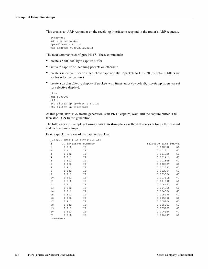
Example of Using Timestamps
This creates an ARP responder on the receiving interface to respond to the router’s ARP requests.
ethernet2add arp responderip-address 1.1.2.20mac-address 0000.2222.2222
The next commands configure PKTS. These commands:
• create a 5,000,000 byte capture buffer
• activate capture of incoming packets on ethernet2
• create a selective filter on ethernet2 to capture only IP packets to 1.1.2.20 (by default, filters are set for selective capture)
• create a display filter to display IP packets with timestamps (by default, timestamp filters are set for selective display).
pktsadd 5000000et2 inet2 filter ip ip-dest 1.1.2.20et2 filter ip timestamp
At this point, start TGN traffic generation, start PKTS capture, wait until the capture buffer is full, then stop TGN traffic generation.
The following are examples of using show timestamp to view the differences between the transmit and receive timestamps.
First, a quick overview of the captured packets:
p4700a-(PKTS:1 of 21739)#sh all# TD interface summary relative time length1 I Et2 IP 0.000990 602 I Et2 IP 0.001211 603 I Et2 IP 0.001320 604 I Et2 IP 0.001419 605 I Et2 IP 0.001869 606 I Et2 IP 0.002587 607 I Et2 IP 0.002793 608 I Et2 IP 0.002904 609 I Et2 IP 0.003006 6010 I Et2 IP 0.003819 6011 I Et2 IP 0.004042 6012 I Et2 IP 0.004152 6013 I Et2 IP 0.004255 6014 I Et2 IP 0.004356 6015 I Et2 IP 0.005198 6016 I Et2 IP 0.005392 6017 I Et2 IP 0.005500 6018 I Et2 IP 0.005602 6019 I Et2 IP 0.005705 6020 I Et2 IP 0.006548 6021 I Et2 IP 0.006747 60 --More--
TGN (Traffic GeNerator) User Manual Cisco Company Confidential5-4
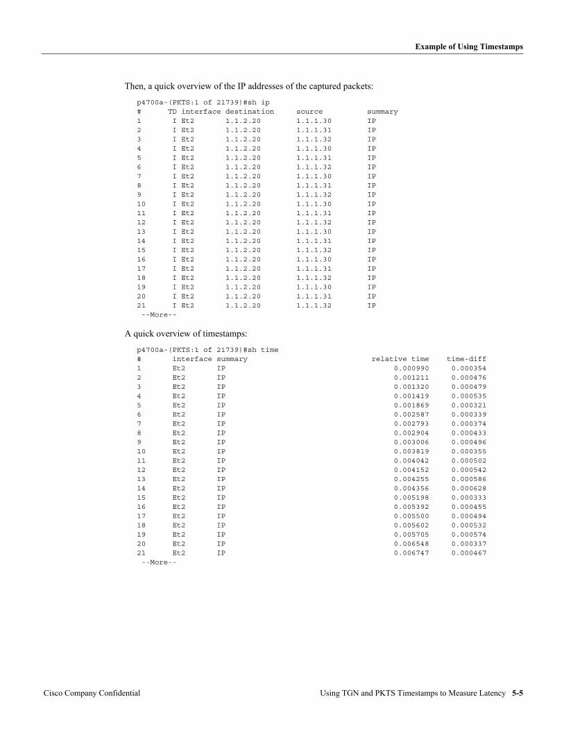
Example of Using Timestamps
Then, a quick overview of the IP addresses of the captured packets:
p4700a-(PKTS:1 of 21739)#sh ip# TD interface destination source summary1 I Et2 1.1.2.20 1.1.1.30 IP 2 I Et2 1.1.2.20 1.1.1.31 IP 3 I Et2 1.1.2.20 1.1.1.32 IP 4 I Et2 1.1.2.20 1.1.1.30 IP 5 I Et2 1.1.2.20 1.1.1.31 IP 6 I Et2 1.1.2.20 1.1.1.32 IP 7 I Et2 1.1.2.20 1.1.1.30 IP 8 I Et2 1.1.2.20 1.1.1.31 IP 9 I Et2 1.1.2.20 1.1.1.32 IP 10 I Et2 1.1.2.20 1.1.1.30 IP 11 I Et2 1.1.2.20 1.1.1.31 IP 12 I Et2 1.1.2.20 1.1.1.32 IP 13 I Et2 1.1.2.20 1.1.1.30 IP 14 I Et2 1.1.2.20 1.1.1.31 IP 15 I Et2 1.1.2.20 1.1.1.32 IP 16 I Et2 1.1.2.20 1.1.1.30 IP 17 I Et2 1.1.2.20 1.1.1.31 IP 18 I Et2 1.1.2.20 1.1.1.32 IP 19 I Et2 1.1.2.20 1.1.1.30 IP 20 I Et2 1.1.2.20 1.1.1.31 IP 21 I Et2 1.1.2.20 1.1.1.32 IP --More--
A quick overview of timestamps:
p4700a-(PKTS:1 of 21739)#sh time# interface summary relative time time-diff1 Et2 IP 0.000990 0.0003542 Et2 IP 0.001211 0.0004763 Et2 IP 0.001320 0.0004794 Et2 IP 0.001419 0.0005355 Et2 IP 0.001869 0.0003216 Et2 IP 0.002587 0.0003397 Et2 IP 0.002793 0.0003748 Et2 IP 0.002904 0.0004339 Et2 IP 0.003006 0.00049610 Et2 IP 0.003819 0.00035511 Et2 IP 0.004042 0.00050212 Et2 IP 0.004152 0.00054213 Et2 IP 0.004255 0.00058614 Et2 IP 0.004356 0.00062815 Et2 IP 0.005198 0.00033316 Et2 IP 0.005392 0.00045517 Et2 IP 0.005500 0.00049418 Et2 IP 0.005602 0.00053219 Et2 IP 0.005705 0.00057420 Et2 IP 0.006548 0.00033721 Et2 IP 0.006747 0.000467 --More--
Cisco Company Confidential Using TGN and PKTS Timestamps to Measure Latency 5-5
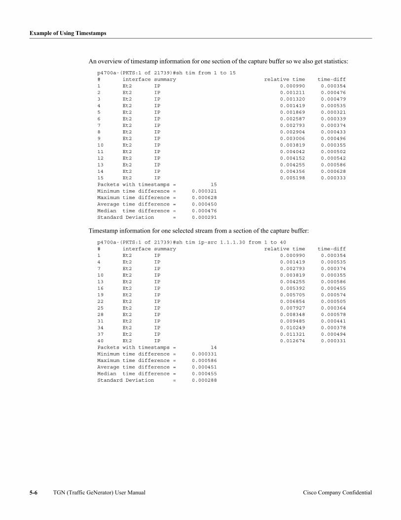
Example of Using Timestamps
An overview of timestamp information for one section of the capture buffer so we also get statistics:
p4700a-(PKTS:1 of 21739)#sh tim from 1 to 15# interface summary relative time time-diff1 Et2 IP 0.000990 0.0003542 Et2 IP 0.001211 0.0004763 Et2 IP 0.001320 0.0004794 Et2 IP 0.001419 0.0005355 Et2 IP 0.001869 0.0003216 Et2 IP 0.002587 0.0003397 Et2 IP 0.002793 0.0003748 Et2 IP 0.002904 0.0004339 Et2 IP 0.003006 0.00049610 Et2 IP 0.003819 0.00035511 Et2 IP 0.004042 0.00050212 Et2 IP 0.004152 0.00054213 Et2 IP 0.004255 0.00058614 Et2 IP 0.004356 0.00062815 Et2 IP 0.005198 0.000333Packets with timestamps = 15Minimum time difference = 0.000321Maximum time difference = 0.000628Average time difference = 0.000450Median time difference = 0.000476Standard Deviation = 0.000291
Timestamp information for one selected stream from a section of the capture buffer:
p4700a-(PKTS:1 of 21739)#sh tim ip-src 1.1.1.30 from 1 to 40# interface summary relative time time-diff1 Et2 IP 0.000990 0.0003544 Et2 IP 0.001419 0.0005357 Et2 IP 0.002793 0.00037410 Et2 IP 0.003819 0.00035513 Et2 IP 0.004255 0.00058616 Et2 IP 0.005392 0.00045519 Et2 IP 0.005705 0.00057422 Et2 IP 0.006854 0.00050525 Et2 IP 0.007927 0.00036428 Et2 IP 0.008348 0.00057831 Et2 IP 0.009485 0.00044134 Et2 IP 0.010249 0.00037837 Et2 IP 0.011321 0.00049440 Et2 IP 0.012674 0.000331Packets with timestamps = 14Minimum time difference = 0.000331Maximum time difference = 0.000586Average time difference = 0.000451Median time difference = 0.000455Standard Deviation = 0.000288
TGN (Traffic GeNerator) User Manual Cisco Company Confidential5-6
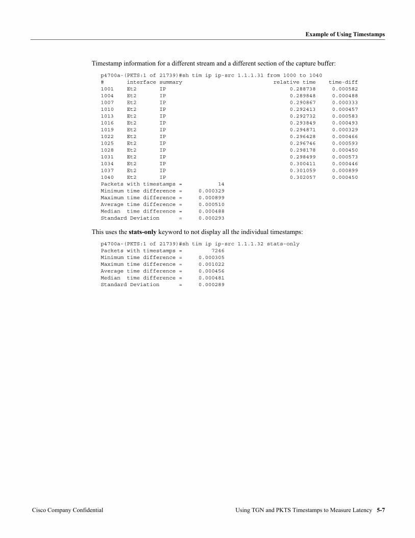
Example of Using Timestamps
Timestamp information for a different stream and a different section of the capture buffer:
p4700a-(PKTS:1 of 21739)#sh tim ip ip-src 1.1.1.31 from 1000 to 1040# interface summary relative time time-diff1001 Et2 IP 0.288738 0.0005821004 Et2 IP 0.289848 0.0004881007 Et2 IP 0.290867 0.0003331010 Et2 IP 0.292413 0.0004571013 Et2 IP 0.292732 0.0005831016 Et2 IP 0.293849 0.0004931019 Et2 IP 0.294871 0.0003291022 Et2 IP 0.296428 0.0004661025 Et2 IP 0.296746 0.0005931028 Et2 IP 0.298178 0.0004501031 Et2 IP 0.298499 0.0005731034 Et2 IP 0.300411 0.0004461037 Et2 IP 0.301059 0.0008991040 Et2 IP 0.302057 0.000450Packets with timestamps = 14Minimum time difference = 0.000329Maximum time difference = 0.000899Average time difference = 0.000510Median time difference = 0.000488Standard Deviation = 0.000293
This uses the stats-only keyword to not display all the individual timestamps:
p4700a-(PKTS:1 of 21739)#sh tim ip ip-src 1.1.1.32 stats-onlyPackets with timestamps = 7246Minimum time difference = 0.000305Maximum time difference = 0.001022Average time difference = 0.000456Median time difference = 0.000481Standard Deviation = 0.000289
Cisco Company Confidential Using TGN and PKTS Timestamps to Measure Latency 5-7

Example of Using Timestamps
TGN (Traffic GeNerator) User Manual Cisco Company Confidential5-8
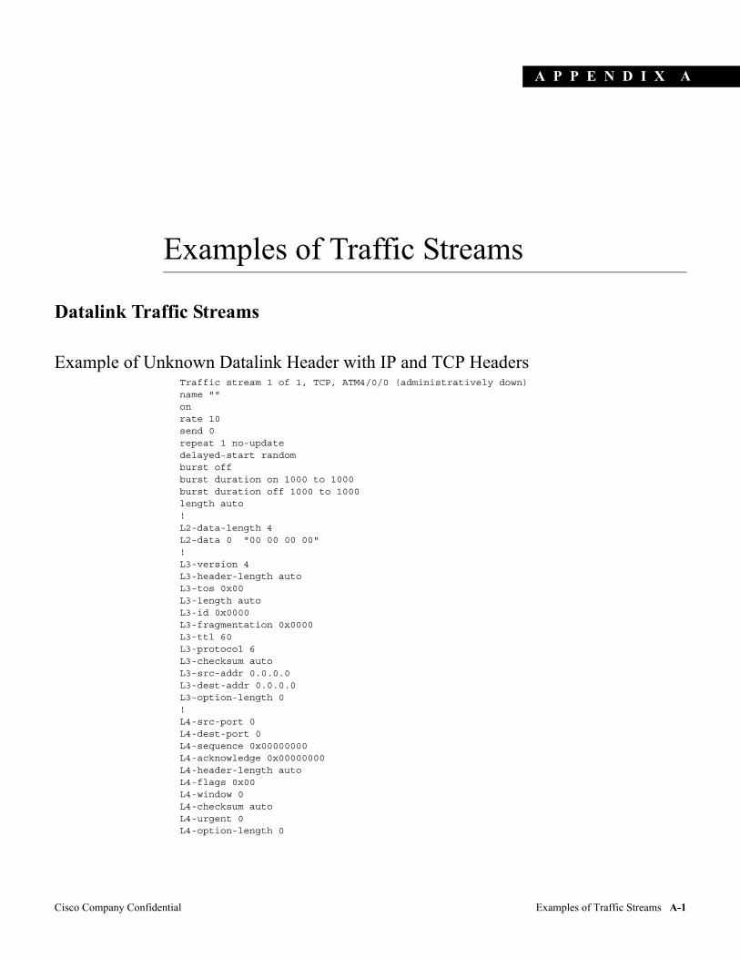
A P P E N D I X
Cisco Company Confidential Examples of Traffic Streams
A
Examples of Traffic Streams
Datalink Traffic Streams
Example of Unknown Datalink Header with IP and TCP HeadersTraffic stream 1 of 1, TCP, ATM4/0/0 (administratively down)name ""onrate 10send 0repeat 1 no-updatedelayed-start randomburst offburst duration on 1000 to 1000burst duration off 1000 to 1000length auto!L2-data-length 4L2-data 0 "00 00 00 00"!L3-version 4L3-header-length autoL3-tos 0x00L3-length autoL3-id 0x0000L3-fragmentation 0x0000L3-ttl 60L3-protocol 6L3-checksum autoL3-src-addr 0.0.0.0L3-dest-addr 0.0.0.0L3-option-length 0!L4-src-port 0L4-dest-port 0L4-sequence 0x00000000L4-acknowledge 0x00000000L4-header-length autoL4-flags 0x00L4-window 0L4-checksum autoL4-urgent 0L4-option-length 0
A-1
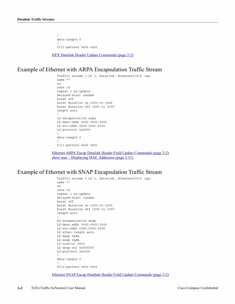
Datalink Traffic Streams
!data-length 0!fill-pattern 0x00 0x01
HEX Datalink Header Update Commands (page 2-2)
Example of Ethernet with ARPA Encapsulation Traffic StreamTraffic stream 1 of 1, Datalink, Ethernet0/0/0 (up)name ""onrate 10repeat 1 no-updatedelayed-start randomburst offburst duration on 1000 to 1000burst duration off 1000 to 1000length auto!L2-encapsulation arpaL2-dest-addr 0000.0000.0000L2-src-addr 0000.0000.0000L2-protocol 0x0000!data-length 0!fill-pattern 0x00 0x01
Ethernet ARPA Encap Datalink Header Field Update Commands (page 2-2) show mac – Displaying MAC Addresses (page 2-51)
Example of Ethernet with SNAP Encapsulation Traffic StreamTraffic stream 1 of 1, Datalink, Ethernet0/0/0 (up)name ""onrate 10repeat 1 no-updatedelayed-start randomburst offburst duration on 1000 to 1000burst duration off 1000 to 1000length auto!L2-encapsulation snapL2-dest-addr 0000.0000.0000L2-src-addr 0000.0000.0000L2-ether-length autoL2-dsap 0xAAL2-ssap 0xAAL2-control 0x03L2-snap-oui 0x000000L2-protocol 0x0000!data-length 0!fill-pattern 0x00 0x01
Ethernet SNAP Encap Datalink Header Field Update Commands (page 2-2)
TGN (Traffic GeNerator) User Manual Cisco Company ConfidentialA-2
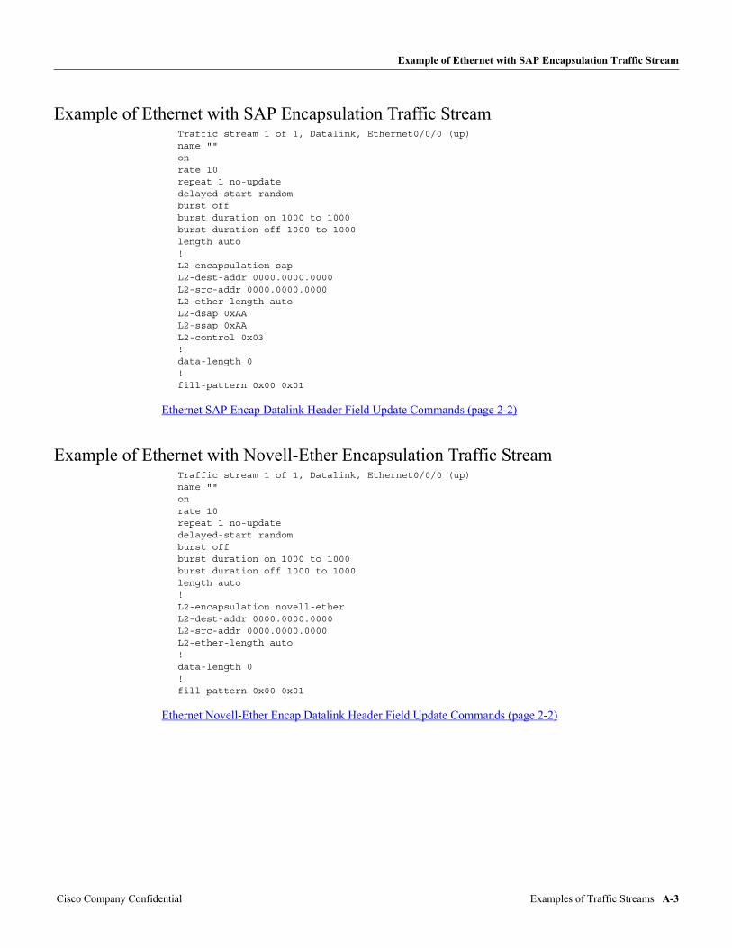
Example of Ethernet with SAP Encapsulation Traffic Stream
Example of Ethernet with SAP Encapsulation Traffic StreamTraffic stream 1 of 1, Datalink, Ethernet0/0/0 (up)name ""onrate 10repeat 1 no-updatedelayed-start randomburst offburst duration on 1000 to 1000burst duration off 1000 to 1000length auto!L2-encapsulation sapL2-dest-addr 0000.0000.0000L2-src-addr 0000.0000.0000L2-ether-length autoL2-dsap 0xAAL2-ssap 0xAAL2-control 0x03!data-length 0!fill-pattern 0x00 0x01
Ethernet SAP Encap Datalink Header Field Update Commands (page 2-2)
Example of Ethernet with Novell-Ether Encapsulation Traffic StreamTraffic stream 1 of 1, Datalink, Ethernet0/0/0 (up)name ""onrate 10repeat 1 no-updatedelayed-start randomburst offburst duration on 1000 to 1000burst duration off 1000 to 1000length auto!L2-encapsulation novell-etherL2-dest-addr 0000.0000.0000L2-src-addr 0000.0000.0000L2-ether-length auto!data-length 0!fill-pattern 0x00 0x01
Ethernet Novell-Ether Encap Datalink Header Field Update Commands (page 2-2)
Cisco Company Confidential Examples of Traffic Streams A-3
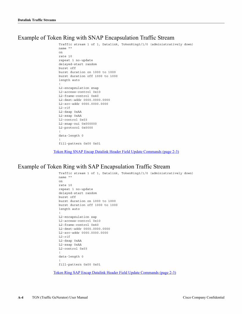
Datalink Traffic Streams
Example of Token Ring with SNAP Encapsulation Traffic StreamTraffic stream 1 of 1, Datalink, TokenRing3/1/0 (administratively down)name ""onrate 10repeat 1 no-updatedelayed-start randomburst offburst duration on 1000 to 1000burst duration off 1000 to 1000length auto!L2-encapsulation snapL2-access-control 0x10L2-frame-control 0x40L2-dest-addr 0000.0000.0000L2-src-addr 0000.0000.0000L2-rif L2-dsap 0xAAL2-ssap 0xAAL2-control 0x03L2-snap-oui 0x000000L2-protocol 0x0000!data-length 0!fill-pattern 0x00 0x01
Token Ring SNAP Encap Datalink Header Field Update Commands (page 2-3)
Example of Token Ring with SAP Encapsulation Traffic StreamTraffic stream 1 of 1, Datalink, TokenRing3/1/0 (administratively down)name ""onrate 10repeat 1 no-updatedelayed-start randomburst offburst duration on 1000 to 1000burst duration off 1000 to 1000length auto!L2-encapsulation sapL2-access-control 0x10L2-frame-control 0x40L2-dest-addr 0000.0000.0000L2-src-addr 0000.0000.0000L2-rif L2-dsap 0xAAL2-ssap 0xAAL2-control 0x03!data-length 0!fill-pattern 0x00 0x01
Token Ring SAP Encap Datalink Header Field Update Commands (page 2-3)
TGN (Traffic GeNerator) User Manual Cisco Company ConfidentialA-4
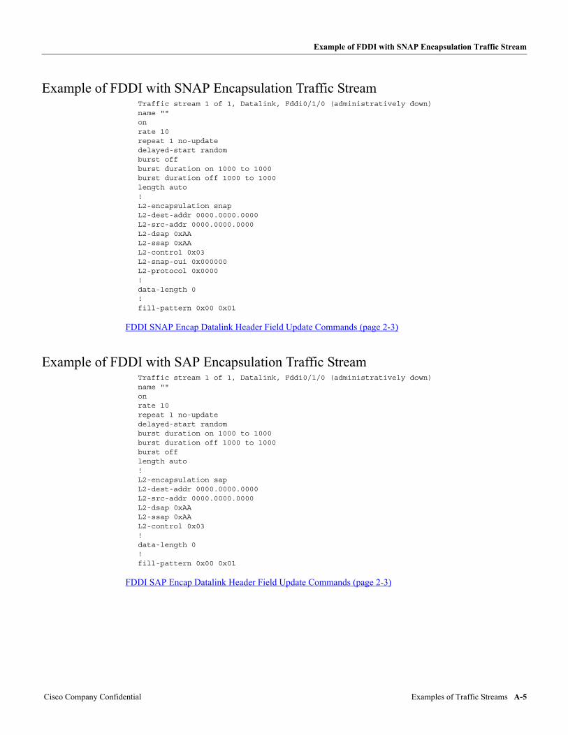
Example of FDDI with SNAP Encapsulation Traffic Stream
Example of FDDI with SNAP Encapsulation Traffic StreamTraffic stream 1 of 1, Datalink, Fddi0/1/0 (administratively down)name ""onrate 10repeat 1 no-updatedelayed-start randomburst offburst duration on 1000 to 1000burst duration off 1000 to 1000length auto!L2-encapsulation snapL2-dest-addr 0000.0000.0000L2-src-addr 0000.0000.0000L2-dsap 0xAAL2-ssap 0xAAL2-control 0x03L2-snap-oui 0x000000L2-protocol 0x0000!data-length 0!fill-pattern 0x00 0x01
FDDI SNAP Encap Datalink Header Field Update Commands (page 2-3)
Example of FDDI with SAP Encapsulation Traffic StreamTraffic stream 1 of 1, Datalink, Fddi0/1/0 (administratively down)name ""onrate 10repeat 1 no-updatedelayed-start randomburst duration on 1000 to 1000burst duration off 1000 to 1000burst offlength auto!L2-encapsulation sapL2-dest-addr 0000.0000.0000L2-src-addr 0000.0000.0000L2-dsap 0xAAL2-ssap 0xAAL2-control 0x03!data-length 0!fill-pattern 0x00 0x01
FDDI SAP Encap Datalink Header Field Update Commands (page 2-3)
Cisco Company Confidential Examples of Traffic Streams A-5
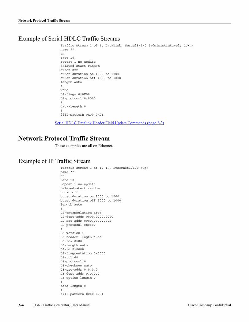
Network Protocol Traffic Stream
Example of Serial HDLC Traffic StreamsTraffic stream 1 of 1, Datalink, Serial8/1/0 (administratively down)name ""onrate 10repeat 1 no-updatedelayed-start randomburst offburst duration on 1000 to 1000burst duration off 1000 to 1000length auto!HDLCL2-flags 0x0F00L2-protocol 0x0000!data-length 0!fill-pattern 0x00 0x01
Serial HDLC Datalink Header Field Update Commands (page 2-3)
Network Protocol Traffic StreamThese examples are all on Ethernet.
Example of IP Traffic StreamTraffic stream 1 of 1, IP, Ethernet1/1/0 (up)name ""onrate 10repeat 1 no-updatedelayed-start randomburst offburst duration on 1000 to 1000burst duration off 1000 to 1000length auto!L2-encapsulation arpaL2-dest-addr 0000.0000.0000L2-src-addr 0000.0000.0000L2-protocol 0x0800!L3-version 4L3-header-length autoL3-tos 0x00L3-length autoL3-id 0x0000L3-fragmentation 0x0000L3-ttl 60L3-protocol 0L3-checksum autoL3-src-addr 0.0.0.0L3-dest-addr 0.0.0.0L3-option-length 0!data-length 0!fill-pattern 0x00 0x01
TGN (Traffic GeNerator) User Manual Cisco Company ConfidentialA-6
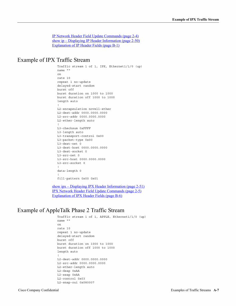
Example of IPX Traffic Stream
IP Network Header Field Update Commands (page 2-4) show ip – Displaying IP Header Information (page 2-50) Explanation of IP Header Fields (page B-1)
Example of IPX Traffic StreamTraffic stream 1 of 1, IPX, Ethernet1/1/0 (up)name ""onrate 10repeat 1 no-updatedelayed-start randomburst offburst duration on 1000 to 1000burst duration off 1000 to 1000length auto!L2-encapsulation novell-etherL2-dest-addr 0000.0000.0000L2-src-addr 0000.0000.0000L2-ether-length auto!L3-checksum 0xFFFFL3-length autoL3-transport-control 0x00L3-packet-type 0x00L3-dest-net 0L3-dest-host 0000.0000.0000L3-dest-socket 0L3-src-net 0L3-src-host 0000.0000.0000L3-src-socket 0!data-length 0!fill-pattern 0x00 0x01
show ipx – Displaying IPX Header Information (page 2-51) IPX Network Header Field Update Commands (page 2-5) Explanation of IPX Header Fields (page B-6)
Example of AppleTalk Phase 2 Traffic StreamTraffic stream 1 of 1, APPLE, Ethernet1/1/0 (up)name ""onrate 10repeat 1 no-updatedelayed-start randomburst offburst duration on 1000 to 1000burst duration off 1000 to 1000length auto!L2-dest-addr 0000.0000.0000L2-src-addr 0000.0000.0000L2-ether-length autoL2-dsap 0xAAL2-ssap 0xAAL2-control 0x03L2-snap-oui 0x080007
Cisco Company Confidential Examples of Traffic Streams A-7
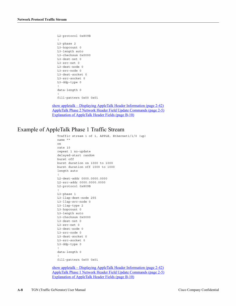
Network Protocol Traffic Stream
L2-protocol 0x809B!L3-phase 2L3-hopcount 0L3-length autoL3-checksum 0x0000L3-dest-net 0L3-src-net 0L3-dest-node 0L3-src-node 0L3-dest-socket 0L3-src-socket 0L3-ddp-type 0!data-length 0!fill-pattern 0x00 0x01
show appletalk – Displaying AppleTalk Header Information (page 2-42) AppleTalk Phase 2 Network Header Field Update Commands (page 2-5) Explanation of AppleTalk Header Fields (page B-10)
Example of AppleTalk Phase 1 Traffic StreamTraffic stream 1 of 1, APPLE, Ethernet1/1/0 (up)name ""onrate 10repeat 1 no-updatedelayed-start randomburst offburst duration on 1000 to 1000burst duration off 1000 to 1000length auto!L2-dest-addr 0000.0000.0000L2-src-addr 0000.0000.0000L2-protocol 0x809B!L3-phase 1L3-llap-dest-node 255L3-llap-src-node 0L3-llap-type 2L3-hopcount 0L3-length autoL3-checksum 0x0000L3-dest-net 0L3-src-net 0L3-dest-node 0L3-src-node 0L3-dest-socket 0L3-src-socket 0L3-ddp-type 0!data-length 0!fill-pattern 0x00 0x01
show appletalk – Displaying AppleTalk Header Information (page 2-42) AppleTalk Phase 1 Network Header Field Update Commands (page 2-5) Explanation of AppleTalk Header Fields (page B-10)
TGN (Traffic GeNerator) User Manual Cisco Company ConfidentialA-8
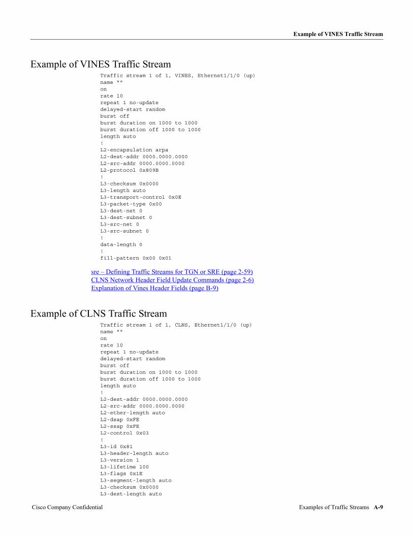
Example of VINES Traffic Stream
Example of VINES Traffic StreamTraffic stream 1 of 1, VINES, Ethernet1/1/0 (up)name ""onrate 10repeat 1 no-updatedelayed-start randomburst offburst duration on 1000 to 1000burst duration off 1000 to 1000length auto!L2-encapsulation arpaL2-dest-addr 0000.0000.0000L2-src-addr 0000.0000.0000L2-protocol 0x809B!L3-checksum 0x0000L3-length autoL3-transport-control 0x0EL3-packet-type 0x00L3-dest-net 0L3-dest-subnet 0L3-src-net 0L3-src-subnet 0!data-length 0!fill-pattern 0x00 0x01
sre – Defining Traffic Streams for TGN or SRE (page 2-59) CLNS Network Header Field Update Commands (page 2-6) Explanation of Vines Header Fields (page B-9)
Example of CLNS Traffic StreamTraffic stream 1 of 1, CLNS, Ethernet1/1/0 (up)name ""onrate 10repeat 1 no-updatedelayed-start randomburst offburst duration on 1000 to 1000burst duration off 1000 to 1000length auto!L2-dest-addr 0000.0000.0000L2-src-addr 0000.0000.0000L2-ether-length autoL2-dsap 0xFEL2-ssap 0xFEL2-control 0x03!L3-id 0x81L3-header-length autoL3-version 1L3-lifetime 100L3-flags 0x1EL3-segment-length autoL3-checksum 0x0000L3-dest-length auto
Cisco Company Confidential Examples of Traffic Streams A-9
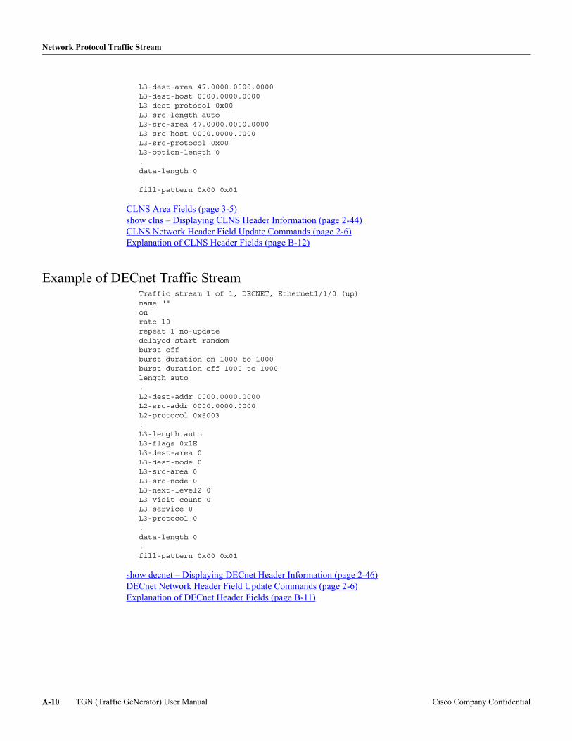
Network Protocol Traffic Stream
L3-dest-area 47.0000.0000.0000L3-dest-host 0000.0000.0000L3-dest-protocol 0x00L3-src-length autoL3-src-area 47.0000.0000.0000L3-src-host 0000.0000.0000L3-src-protocol 0x00L3-option-length 0!data-length 0!fill-pattern 0x00 0x01
CLNS Area Fields (page 3-5) show clns – Displaying CLNS Header Information (page 2-44) CLNS Network Header Field Update Commands (page 2-6) Explanation of CLNS Header Fields (page B-12)
Example of DECnet Traffic StreamTraffic stream 1 of 1, DECNET, Ethernet1/1/0 (up)name ""onrate 10repeat 1 no-updatedelayed-start randomburst offburst duration on 1000 to 1000burst duration off 1000 to 1000length auto!L2-dest-addr 0000.0000.0000L2-src-addr 0000.0000.0000L2-protocol 0x6003!L3-length autoL3-flags 0x1EL3-dest-area 0L3-dest-node 0L3-src-area 0L3-src-node 0L3-next-level2 0L3-visit-count 0L3-service 0L3-protocol 0!data-length 0!fill-pattern 0x00 0x01
show decnet – Displaying DECnet Header Information (page 2-46) DECnet Network Header Field Update Commands (page 2-6) Explanation of DECnet Header Fields (page B-11)
TGN (Traffic GeNerator) User Manual Cisco Company ConfidentialA-10
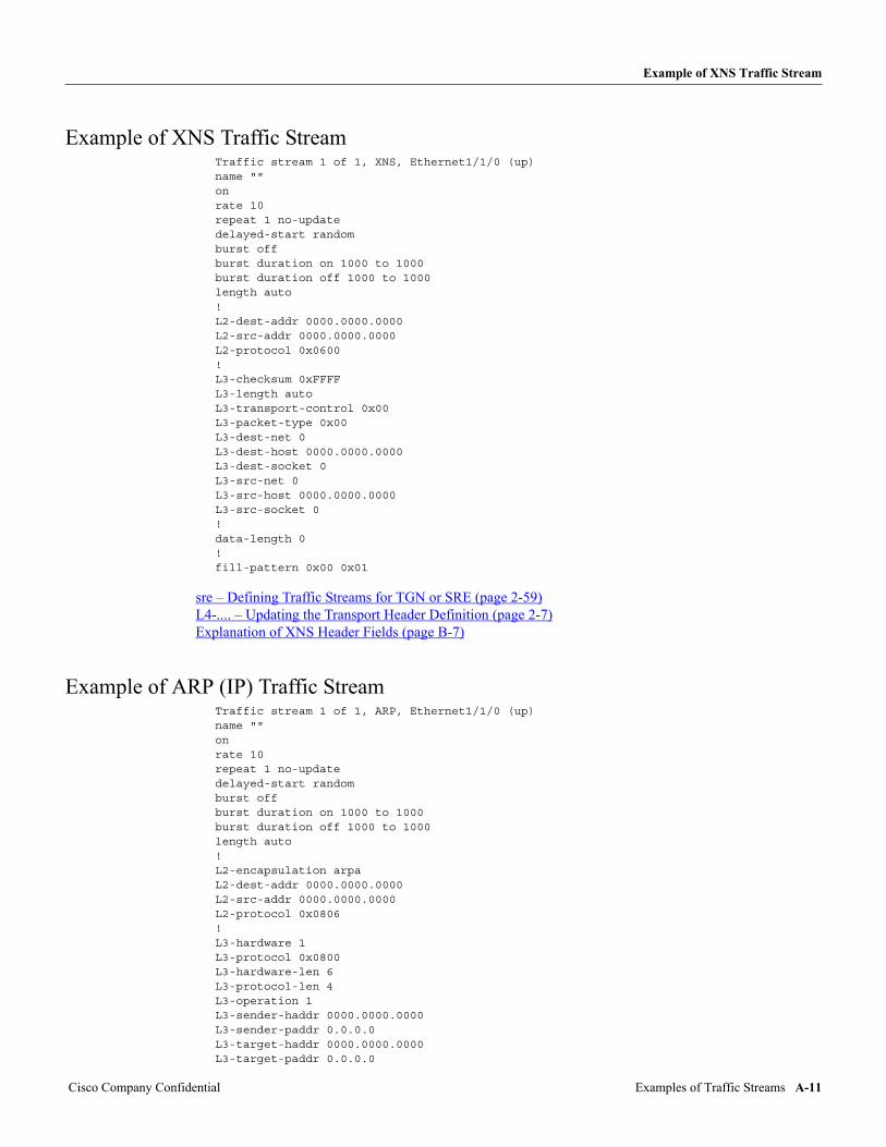
Example of XNS Traffic Stream
Example of XNS Traffic StreamTraffic stream 1 of 1, XNS, Ethernet1/1/0 (up)name ""onrate 10repeat 1 no-updatedelayed-start randomburst offburst duration on 1000 to 1000burst duration off 1000 to 1000length auto!L2-dest-addr 0000.0000.0000L2-src-addr 0000.0000.0000L2-protocol 0x0600!L3-checksum 0xFFFFL3-length autoL3-transport-control 0x00L3-packet-type 0x00L3-dest-net 0L3-dest-host 0000.0000.0000L3-dest-socket 0L3-src-net 0L3-src-host 0000.0000.0000L3-src-socket 0!data-length 0!fill-pattern 0x00 0x01
sre – Defining Traffic Streams for TGN or SRE (page 2-59) L4-.... – Updating the Transport Header Definition (page 2-7) Explanation of XNS Header Fields (page B-7)
Example of ARP (IP) Traffic StreamTraffic stream 1 of 1, ARP, Ethernet1/1/0 (up)name ""onrate 10repeat 1 no-updatedelayed-start randomburst offburst duration on 1000 to 1000burst duration off 1000 to 1000length auto!L2-encapsulation arpaL2-dest-addr 0000.0000.0000L2-src-addr 0000.0000.0000L2-protocol 0x0806!L3-hardware 1L3-protocol 0x0800L3-hardware-len 6L3-protocol-len 4L3-operation 1L3-sender-haddr 0000.0000.0000L3-sender-paddr 0.0.0.0L3-target-haddr 0000.0000.0000L3-target-paddr 0.0.0.0
Cisco Company Confidential Examples of Traffic Streams A-11
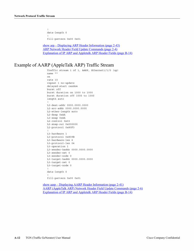
Network Protocol Traffic Stream
!data-length 0!fill-pattern 0x00 0x01
show arp – Displaying ARP Header Information (page 2-43) ARP Network Header Field Update Commands (page 2-4) Explanation of IP ARP and Appletalk ARP Header Fields (page B-14)
Example of AARP (AppleTalk ARP) Traffic StreamTraffic stream 1 of 1, AARP, Ethernet1/1/0 (up)name ""onrate 10repeat 1 no-updatedelayed-start randomburst offburst duration on 1000 to 1000burst duration off 1000 to 1000length auto!L2-dest-addr 0000.0000.0000L2-src-addr 0000.0000.0000L2-ether-length autoL2-dsap 0xAAL2-ssap 0xAAL2-control 0x03L2-snap-oui 0x000000L2-protocol 0x80F3!L3-hardware 1L3-protocol 0x809BL3-hardware-len 6L3-protocol-len 04L3-operation 1L3-sender-haddr 0000.0000.0000L3-sender-net 0L3-sender-node 0L3-target-haddr 0000.0000.0000L3-target-net 0L3-target-node 0!data-length 0!fill-pattern 0x00 0x01
show aarp – Displaying AARP Header Information (page 2-41) AARP (AppleTalk ARP) Network Header Field Update Commands (page 2-6) Explanation of IP ARP and Appletalk ARP Header Fields (page B-14)
TGN (Traffic GeNerator) User Manual Cisco Company ConfidentialA-12
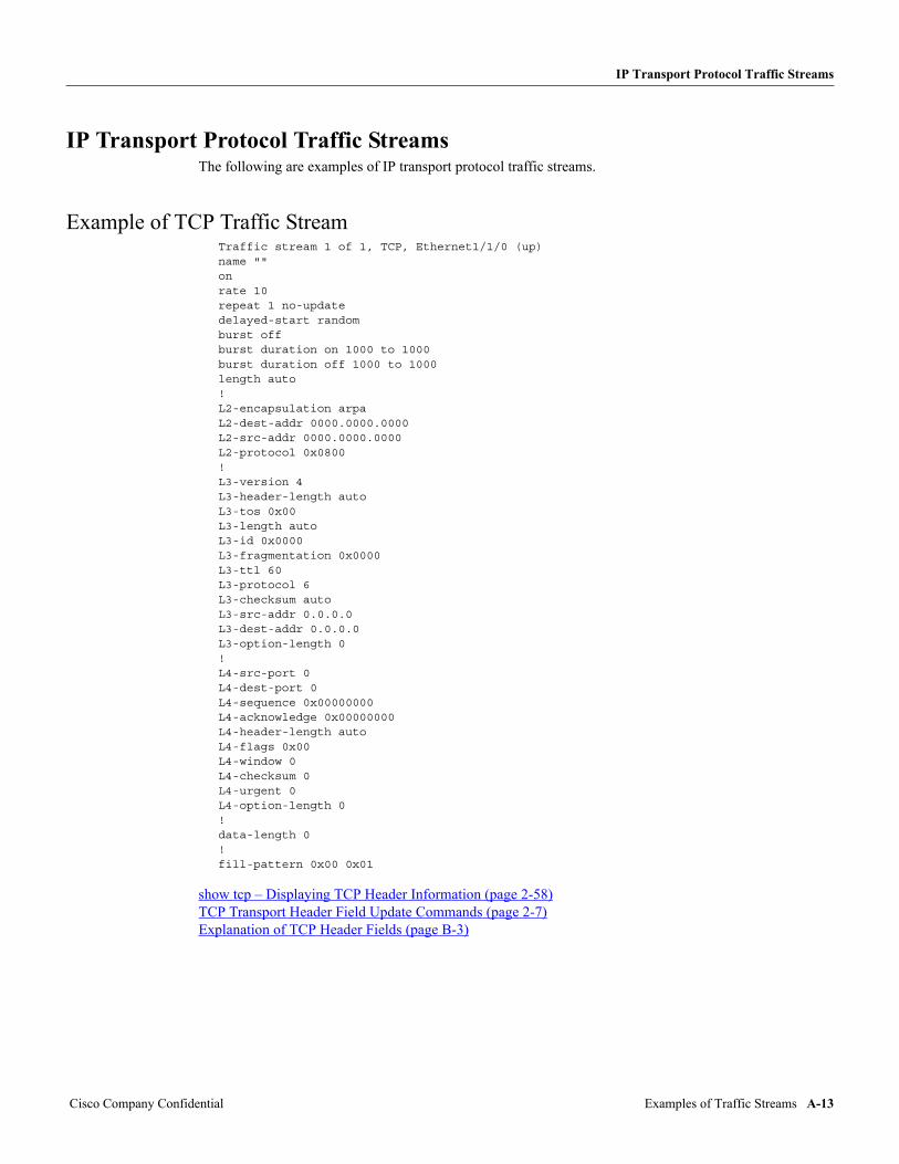
IP Transport Protocol Traffic Streams
IP Transport Protocol Traffic StreamsThe following are examples of IP transport protocol traffic streams.
Example of TCP Traffic StreamTraffic stream 1 of 1, TCP, Ethernet1/1/0 (up)name ""onrate 10repeat 1 no-updatedelayed-start randomburst offburst duration on 1000 to 1000burst duration off 1000 to 1000length auto!L2-encapsulation arpaL2-dest-addr 0000.0000.0000L2-src-addr 0000.0000.0000L2-protocol 0x0800!L3-version 4L3-header-length autoL3-tos 0x00L3-length autoL3-id 0x0000L3-fragmentation 0x0000L3-ttl 60L3-protocol 6L3-checksum autoL3-src-addr 0.0.0.0L3-dest-addr 0.0.0.0L3-option-length 0!L4-src-port 0L4-dest-port 0L4-sequence 0x00000000L4-acknowledge 0x00000000L4-header-length autoL4-flags 0x00L4-window 0L4-checksum 0L4-urgent 0L4-option-length 0!data-length 0!fill-pattern 0x00 0x01
show tcp – Displaying TCP Header Information (page 2-58) TCP Transport Header Field Update Commands (page 2-7) Explanation of TCP Header Fields (page B-3)
Cisco Company Confidential Examples of Traffic Streams A-13
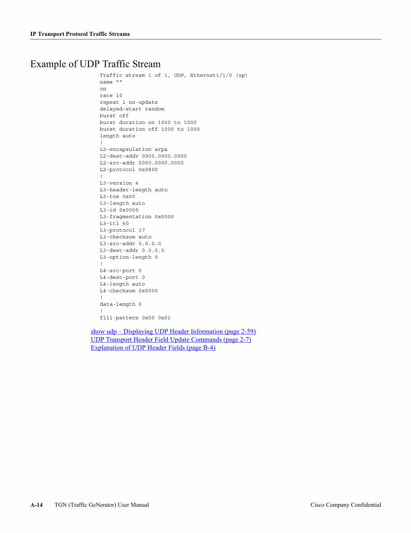
IP Transport Protocol Traffic Streams
Example of UDP Traffic StreamTraffic stream 1 of 1, UDP, Ethernet1/1/0 (up)name ""onrate 10repeat 1 no-updatedelayed-start randomburst offburst duration on 1000 to 1000burst duration off 1000 to 1000length auto!L2-encapsulation arpaL2-dest-addr 0000.0000.0000L2-src-addr 0000.0000.0000L2-protocol 0x0800!L3-version 4L3-header-length autoL3-tos 0x00L3-length autoL3-id 0x0000L3-fragmentation 0x0000L3-ttl 60L3-protocol 17L3-checksum autoL3-src-addr 0.0.0.0L3-dest-addr 0.0.0.0L3-option-length 0!L4-src-port 0L4-dest-port 0L4-length autoL4-checksum 0x0000!data-length 0!fill-pattern 0x00 0x01
show udp – Displaying UDP Header Information (page 2-59) UDP Transport Header Field Update Commands (page 2-7) Explanation of UDP Header Fields (page B-4)
TGN (Traffic GeNerator) User Manual Cisco Company ConfidentialA-14
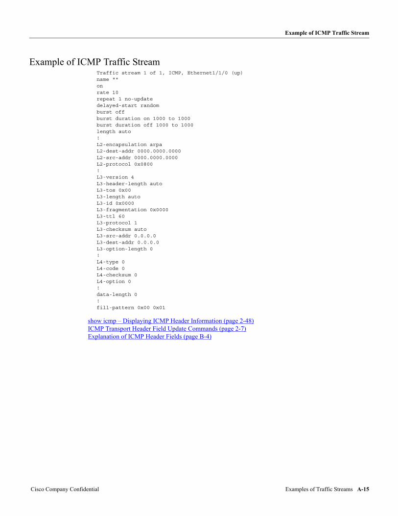
Example of ICMP Traffic Stream
Example of ICMP Traffic StreamTraffic stream 1 of 1, ICMP, Ethernet1/1/0 (up)name ""onrate 10repeat 1 no-updatedelayed-start randomburst offburst duration on 1000 to 1000burst duration off 1000 to 1000length auto!L2-encapsulation arpaL2-dest-addr 0000.0000.0000L2-src-addr 0000.0000.0000L2-protocol 0x0800!L3-version 4L3-header-length autoL3-tos 0x00L3-length autoL3-id 0x0000L3-fragmentation 0x0000L3-ttl 60L3-protocol 1L3-checksum autoL3-src-addr 0.0.0.0L3-dest-addr 0.0.0.0L3-option-length 0!L4-type 0L4-code 0L4-checksum 0L4-option 0!data-length 0!fill-pattern 0x00 0x01
show icmp – Displaying ICMP Header Information (page 2-48) ICMP Transport Header Field Update Commands (page 2-7) Explanation of ICMP Header Fields (page B-4)
Cisco Company Confidential Examples of Traffic Streams A-15

IP Transport Protocol Traffic Streams
Example of IGMP Traffic StreamTraffic stream 1 of 1, IGMP, Ethernet1/1/0 (up)name ""onrate 10repeat 1 no-updatedelayed-start randomburst offburst duration on 1000 to 1000burst duration off 1000 to 1000length auto!L2-encapsulation arpaL2-dest-addr 0000.0000.0000L2-src-addr 0000.0000.0000L2-protocol 0x0800!L3-version 4L3-header-length autoL3-tos 0x00L3-length autoL3-id 0x0000L3-fragmentation 0x0000L3-ttl 60L3-protocol 2L3-checksum autoL3-src-addr 0.0.0.0L3-dest-addr 0.0.0.0L3-option-length 0!L4-version 0L4-type 0L4-checksum 0x0000L4-group-address 0.0.0.0!data-length 0!fill-pattern 0x00 0x01
show igmp – Displaying IGMP Header Information (page 2-48) IGMP Transport Header Field Update Commands (page 2-9) Explanation of IGMP Header Fields (page B-5)
TGN (Traffic GeNerator) User Manual Cisco Company ConfidentialA-16
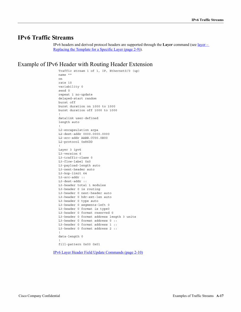
IPv6 Traffic Streams
IPv6 Traffic StreamsIPv6 headers and derived protocol headers are supported through the Layer command (see layer – Replacing the Template for a Specific Layer (page 2-9)).
Example of IPv6 Header with Routing Header ExtensionTraffic stream 1 of 1, IP, Ethernet0/0 (up)name ""onrate 10variability 0send 0repeat 1 no-updatedelayed-start randomburst offburst duration on 1000 to 1000burst duration off 1000 to 1000!datalink user-definedlength auto!L2-encapsulation arpaL2-dest-addr 0000.0000.0000L2-src-addr AABB.CC00.0B00L2-protocol 0x86DD!Layer 3 ipv6L3-version 6L3-traffic-class 0L3-flow-label 0x0L3-payload-length autoL3-next-header autoL3-hop-limit 64L3-src-addr ::L3-dest-addr ::L3-header total 1 modulesL3-header 0 is routingL3-header 0 next-header autoL3-header 0 hdr-ext-len autoL3-header 0 type autoL3-header 0 segments-left 0L3-header 0 format is type0L3-header 0 format reserved 0L3-header 0 format address length 3 unitsL3-header 0 format address 0 ::L3-header 0 format address 1 ::L3-header 0 format address 2 ::!data-length 0!fill-pattern 0x00 0x01
IPv6 Layer Header Field Update Commands (page 2-10)
Cisco Company Confidential Examples of Traffic Streams A-17
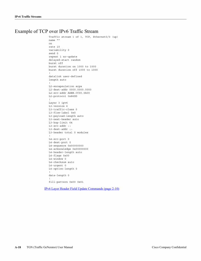
IPv6 Traffic Streams
Example of TCP over IPv6 Traffic StreamTraffic stream 1 of 1, TCP, Ethernet0/0 (up)name ""onrate 10variability 0send 0repeat 1 no-updatedelayed-start randomburst offburst duration on 1000 to 1000burst duration off 1000 to 1000!datalink user-definedlength auto!L2-encapsulation arpaL2-dest-addr 0000.0000.0000L2-src-addr AABB.CC00.0A00L2-protocol 0x86DD!Layer 3 ipv6L3-version 6L3-traffic-class 0L3-flow-label 0x0L3-payload-length autoL3-next-header autoL3-hop-limit 64L3-src-addr ::L3-dest-addr ::L3-header total 0 modules!L4-src-port 0L4-dest-port 0L4-sequence 0x00000000L4-acknowledge 0x00000000L4-header-length autoL4-flags 0x00L4-window 0L4-checksum autoL4-urgent 0L4-option-length 0!data-length 0!fill-pattern 0x00 0x01
IPv6 Layer Header Field Update Commands (page 2-10)
TGN (Traffic GeNerator) User Manual Cisco Company ConfidentialA-18
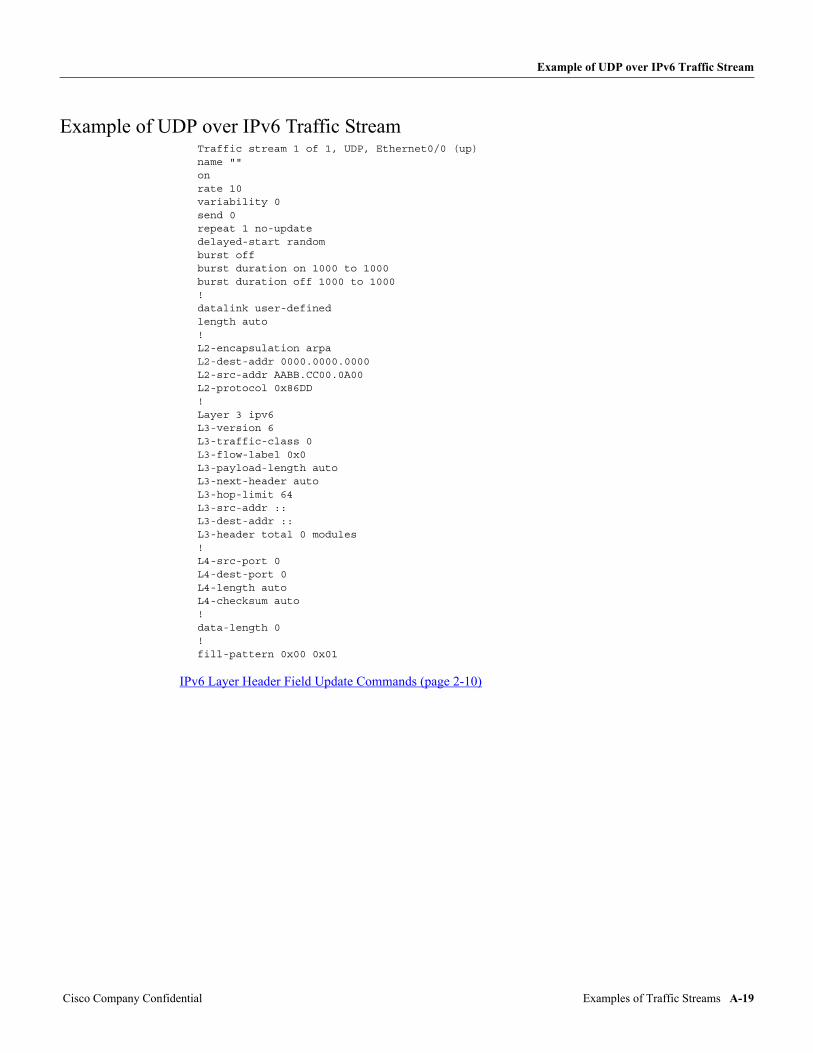
Example of UDP over IPv6 Traffic Stream
Example of UDP over IPv6 Traffic StreamTraffic stream 1 of 1, UDP, Ethernet0/0 (up)name ""onrate 10variability 0send 0repeat 1 no-updatedelayed-start randomburst offburst duration on 1000 to 1000burst duration off 1000 to 1000!datalink user-definedlength auto!L2-encapsulation arpaL2-dest-addr 0000.0000.0000L2-src-addr AABB.CC00.0A00L2-protocol 0x86DD!Layer 3 ipv6L3-version 6L3-traffic-class 0L3-flow-label 0x0L3-payload-length autoL3-next-header autoL3-hop-limit 64L3-src-addr ::L3-dest-addr ::L3-header total 0 modules!L4-src-port 0L4-dest-port 0L4-length autoL4-checksum auto!data-length 0!fill-pattern 0x00 0x01
IPv6 Layer Header Field Update Commands (page 2-10)
Cisco Company Confidential Examples of Traffic Streams A-19
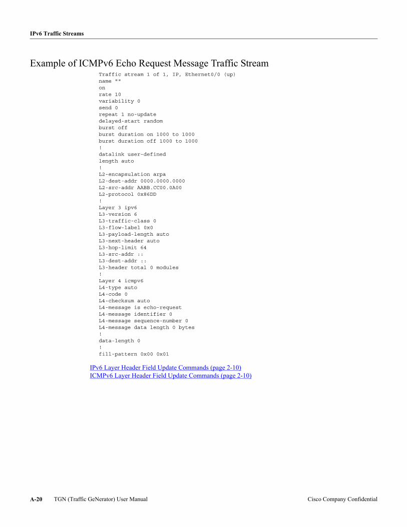
IPv6 Traffic Streams
Example of ICMPv6 Echo Request Message Traffic StreamTraffic stream 1 of 1, IP, Ethernet0/0 (up)name ""onrate 10variability 0send 0repeat 1 no-updatedelayed-start randomburst offburst duration on 1000 to 1000burst duration off 1000 to 1000!datalink user-definedlength auto!L2-encapsulation arpaL2-dest-addr 0000.0000.0000L2-src-addr AABB.CC00.0A00L2-protocol 0x86DD!Layer 3 ipv6L3-version 6L3-traffic-class 0L3-flow-label 0x0L3-payload-length autoL3-next-header autoL3-hop-limit 64L3-src-addr ::L3-dest-addr ::L3-header total 0 modules!Layer 4 icmpv6L4-type autoL4-code 0L4-checksum autoL4-message is echo-requestL4-message identifier 0L4-message sequence-number 0L4-message data length 0 bytes!data-length 0!fill-pattern 0x00 0x01
IPv6 Layer Header Field Update Commands (page 2-10) ICMPv6 Layer Header Field Update Commands (page 2-10)
TGN (Traffic GeNerator) User Manual Cisco Company ConfidentialA-20
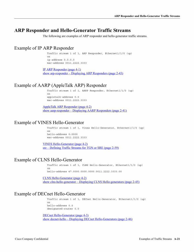
ARP Responder and Hello-Generator Traffic Streams
ARP Responder and Hello-Generator Traffic StreamsThe following are examples of ARP responder and hello-generator traffic streams.
Example of IP ARP ResponderTraffic stream 1 of 1, ARP Responder, Ethernet1/1/0 (up)onip-address 0.0.0.0mac-address 0011.2222.3333
IP ARP Responder (page 4-1) show arp-responder – Displaying ARP Responders (page 2-43)
Example of AARP (AppleTalk ARP) ResponderTraffic stream 1 of 1, AARP Responder, Ethernet1/1/0 (up)onappletalk-address 0.0mac-address 0011.2222.3333
AppleTalk ARP Responder (page 4-2) show aarp-responder – Displaying AARP Responders (page 2-41)
Example of VINES Hello-GeneratorTraffic stream 1 of 1, Vines Hello-Generator, Ethernet1/1/0 (up)onhello-address 0:0000mac-address 0011.2222.3333
VINES Hello-Generator (page 4-2) sre – Defining Traffic Streams for TGN or SRE (page 2-59)
Example of CLNS Hello-GeneratorTraffic stream 1 of 1, CLNS Hello-Generator, Ethernet1/1/0 (up)onhello-address 47.0000.0000.0000.0011.2222.3333.00
CLNS Hello-Generator (page 4-2) show clns-hello-generator – Displaying CLNS Hello-generators (page 2-45)
Example of DECnet Hello-GeneratorTraffic stream 1 of 1, DECnet Hello-Generator, Ethernet1/1/0 (up)onhello-address 0.0designated-router 0.0
DECnet Hello-Generator (page 4-3) show decnet-hello – Displaying DECnet Hello-Generators (page 2-46)
Cisco Company Confidential Examples of Traffic Streams A-21

ARP Responder and Hello-Generator Traffic Streams
TGN (Traffic GeNerator) User Manual Cisco Company ConfidentialA-22
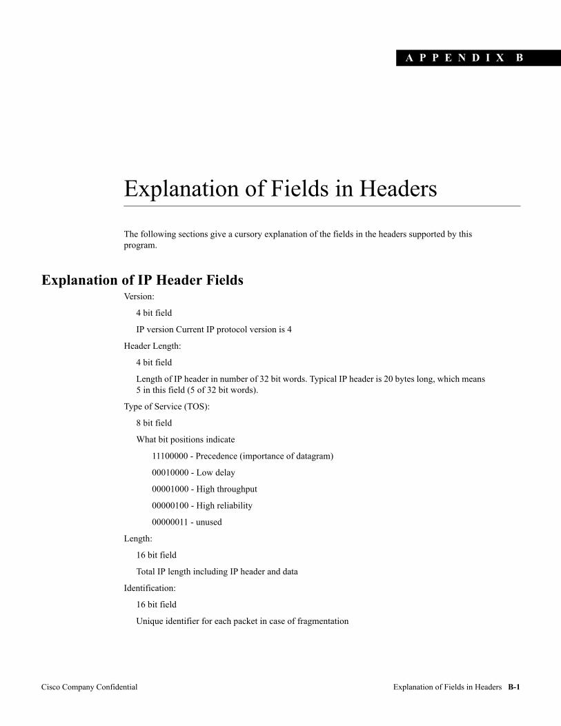
A P P E N D I X
Cisco Company Confidential Explanation of Fields in Headers
B
Explanation of Fields in Headers
The following sections give a cursory explanation of the fields in the headers supported by this program.
Explanation of IP Header FieldsVersion:
4 bit field
IP version Current IP protocol version is 4
Header Length:
4 bit field
Length of IP header in number of 32 bit words. Typical IP header is 20 bytes long, which means 5 in this field (5 of 32 bit words).
Type of Service (TOS):
8 bit field
What bit positions indicate
11100000 - Precedence (importance of datagram)
00010000 - Low delay
00001000 - High throughput
00000100 - High reliability
00000011 - unused
Length:
16 bit field
Total IP length including IP header and data
Identification:
16 bit field
Unique identifier for each packet in case of fragmentation
B-1
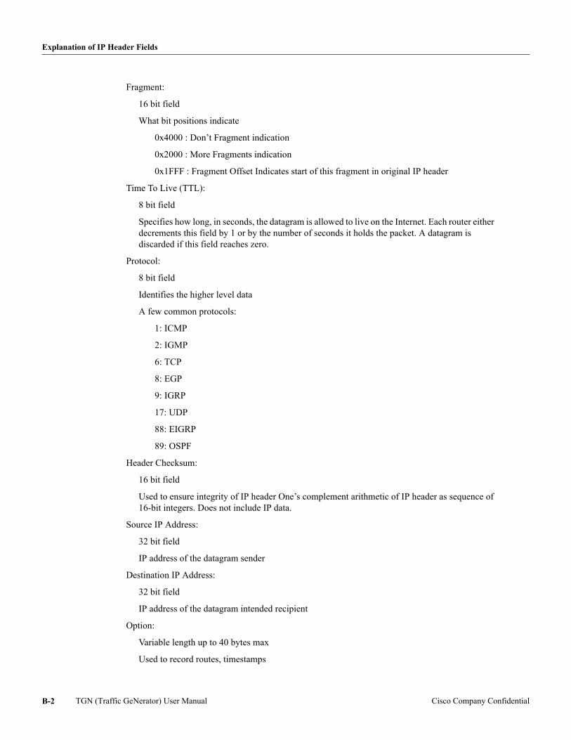
Explanation of IP Header Fields
Fragment:
16 bit field
What bit positions indicate
0x4000 : Don’t Fragment indication
0x2000 : More Fragments indication
0x1FFF : Fragment Offset Indicates start of this fragment in original IP header
Time To Live (TTL):
8 bit field
Specifies how long, in seconds, the datagram is allowed to live on the Internet. Each router either decrements this field by 1 or by the number of seconds it holds the packet. A datagram is discarded if this field reaches zero.
Protocol:
8 bit field
Identifies the higher level data
A few common protocols:
1: ICMP
2: IGMP
6: TCP
8: EGP
9: IGRP
17: UDP
88: EIGRP
89: OSPF
Header Checksum:
16 bit field
Used to ensure integrity of IP header One’s complement arithmetic of IP header as sequence of 16-bit integers. Does not include IP data.
Source IP Address:
32 bit field
IP address of the datagram sender
Destination IP Address:
32 bit field
IP address of the datagram intended recipient
Option:
Variable length up to 40 bytes max
Used to record routes, timestamps
TGN (Traffic GeNerator) User Manual Cisco Company ConfidentialB-2
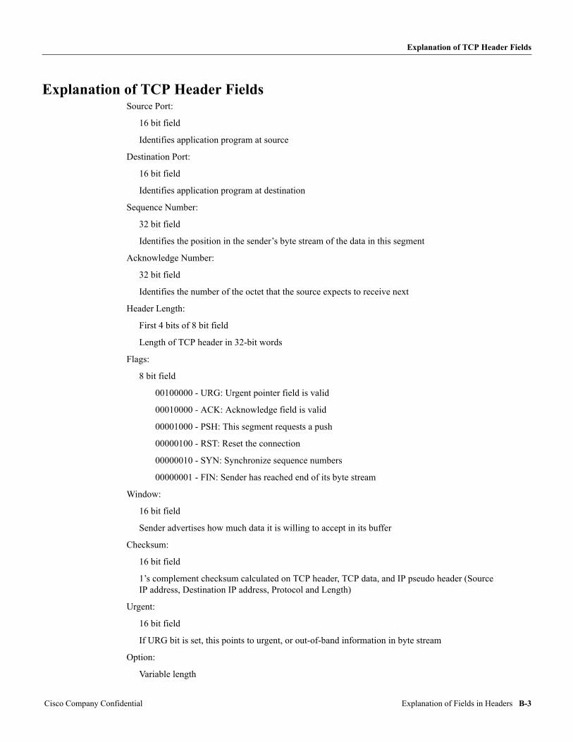
Explanation of TCP Header Fields
Explanation of TCP Header FieldsSource Port:
16 bit field
Identifies application program at source
Destination Port:
16 bit field
Identifies application program at destination
Sequence Number:
32 bit field
Identifies the position in the sender’s byte stream of the data in this segment
Acknowledge Number:
32 bit field
Identifies the number of the octet that the source expects to receive next
Header Length:
First 4 bits of 8 bit field
Length of TCP header in 32-bit words
Flags:
8 bit field
00100000 - URG: Urgent pointer field is valid
00010000 - ACK: Acknowledge field is valid
00001000 - PSH: This segment requests a push
00000100 - RST: Reset the connection
00000010 - SYN: Synchronize sequence numbers
00000001 - FIN: Sender has reached end of its byte stream
Window:
16 bit field
Sender advertises how much data it is willing to accept in its buffer
Checksum:
16 bit field
1’s complement checksum calculated on TCP header, TCP data, and IP pseudo header (Source IP address, Destination IP address, Protocol and Length)
Urgent:
16 bit field
If URG bit is set, this points to urgent, or out-of-band information in byte stream
Option:
Variable length
Cisco Company Confidential Explanation of Fields in Headers B-3
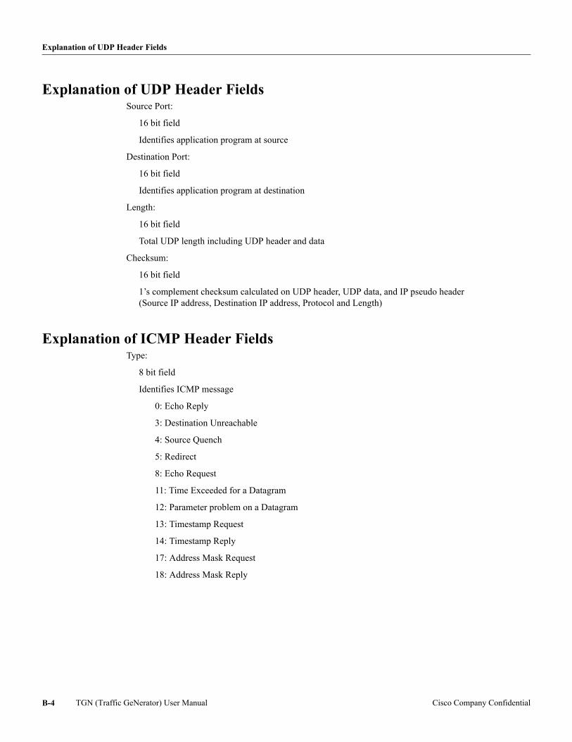
Explanation of UDP Header Fields
Explanation of UDP Header FieldsSource Port:
16 bit field
Identifies application program at source
Destination Port:
16 bit field
Identifies application program at destination
Length:
16 bit field
Total UDP length including UDP header and data
Checksum:
16 bit field
1’s complement checksum calculated on UDP header, UDP data, and IP pseudo header (Source IP address, Destination IP address, Protocol and Length)
Explanation of ICMP Header FieldsType:
8 bit field
Identifies ICMP message
0: Echo Reply
3: Destination Unreachable
4: Source Quench
5: Redirect
8: Echo Request
11: Time Exceeded for a Datagram
12: Parameter problem on a Datagram
13: Timestamp Request
14: Timestamp Reply
17: Address Mask Request
18: Address Mask Reply
TGN (Traffic GeNerator) User Manual Cisco Company ConfidentialB-4
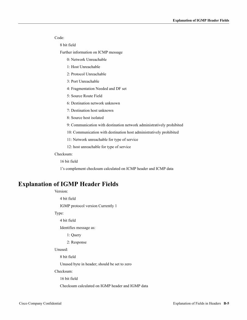
Explanation of IGMP Header Fields
Code:
8 bit field
Further information on ICMP message
0: Network Unreachable
1: Host Unreachable
2: Protocol Unreachable
3: Port Unreachable
4: Fragmentation Needed and DF set
5: Source Route Field
6: Destination network unknown
7: Destination host unknown
8: Source host isolated
9: Communication with destination network administratively prohibited
10: Communication with destination host administratively prohibited
11: Network unreachable for type of service
12: host unreachable for type of service
Checksum:
16 bit field
1’s complement checksum calculated on ICMP header and ICMP data
Explanation of IGMP Header FieldsVersion:
4 bit field
IGMP protocol version Currently 1
Type:
4 bit field
Identifies message as:
1: Query
2: Response
Unused:
8 bit field
Unused byte in header; should be set to zero
Checksum:
16 bit field
Checksum calculated on IGMP header and IGMP data
Cisco Company Confidential Explanation of Fields in Headers B-5
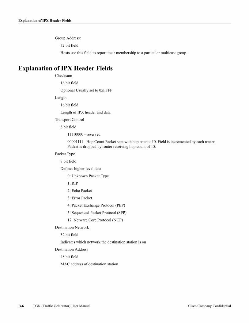
Explanation of IPX Header Fields
Group Address:
32 bit field
Hosts use this field to report their membership to a particular multicast group.
Explanation of IPX Header FieldsChecksum
16 bit field
Optional Usually set to 0xFFFF
Length
16 bit field
Length of IPX header and data
Transport Control
8 bit field
11110000 - reserved
00001111 - Hop Count Packet sent with hop count of 0. Field is incremented by each router. Packet is dropped by router receiving hop count of 15.
Packet Type
8 bit field
Defines higher level data
0: Unknown Packet Type
1: RIP
2: Echo Packet
3: Error Packet
4: Packet Exchange Protocol (PEP)
5: Sequenced Packet Protocol (SPP)
17: Netware Core Protocol (NCP)
Destination Network
32 bit field
Indicates which network the destination station is on
Destination Address
48 bit field
MAC address of destination station
TGN (Traffic GeNerator) User Manual Cisco Company ConfidentialB-6
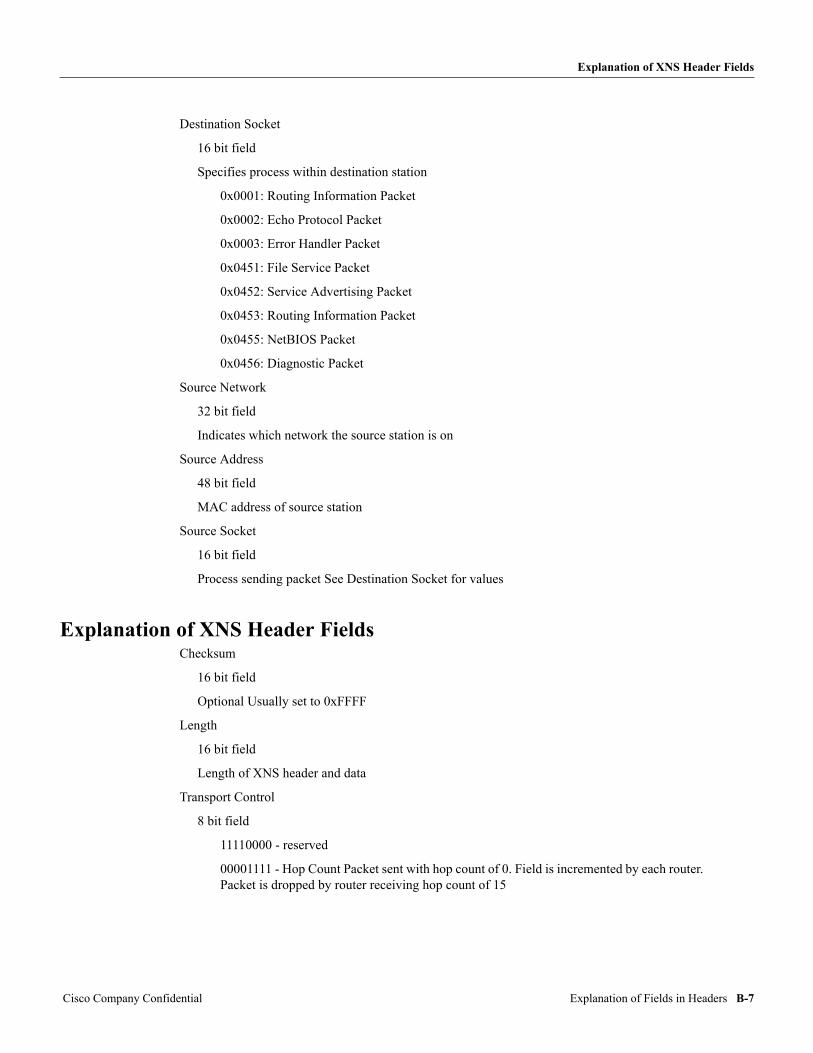
Explanation of XNS Header Fields
Destination Socket
16 bit field
Specifies process within destination station
0x0001: Routing Information Packet
0x0002: Echo Protocol Packet
0x0003: Error Handler Packet
0x0451: File Service Packet
0x0452: Service Advertising Packet
0x0453: Routing Information Packet
0x0455: NetBIOS Packet
0x0456: Diagnostic Packet
Source Network
32 bit field
Indicates which network the source station is on
Source Address
48 bit field
MAC address of source station
Source Socket
16 bit field
Process sending packet See Destination Socket for values
Explanation of XNS Header FieldsChecksum
16 bit field
Optional Usually set to 0xFFFF
Length
16 bit field
Length of XNS header and data
Transport Control
8 bit field
11110000 - reserved
00001111 - Hop Count Packet sent with hop count of 0. Field is incremented by each router. Packet is dropped by router receiving hop count of 15
Cisco Company Confidential Explanation of Fields in Headers B-7
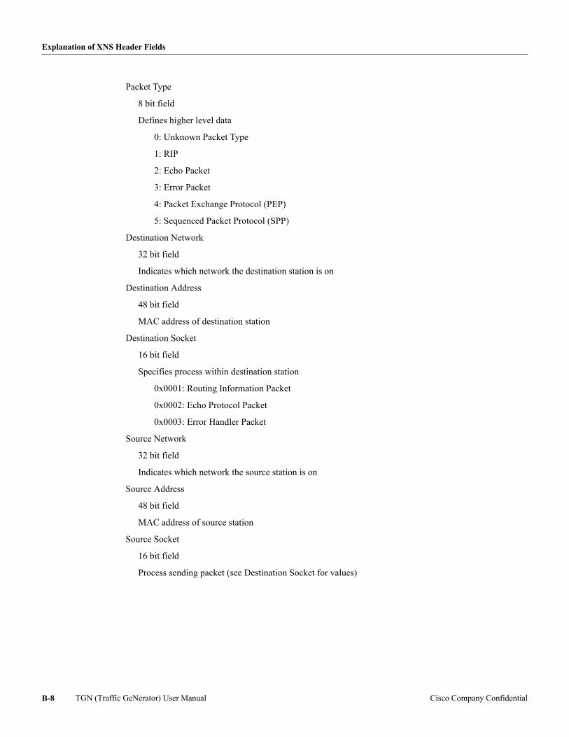
Explanation of XNS Header Fields
Packet Type
8 bit field
Defines higher level data
0: Unknown Packet Type
1: RIP
2: Echo Packet
3: Error Packet
4: Packet Exchange Protocol (PEP)
5: Sequenced Packet Protocol (SPP)
Destination Network
32 bit field
Indicates which network the destination station is on
Destination Address
48 bit field
MAC address of destination station
Destination Socket
16 bit field
Specifies process within destination station
0x0001: Routing Information Packet
0x0002: Echo Protocol Packet
0x0003: Error Handler Packet
Source Network
32 bit field
Indicates which network the source station is on
Source Address
48 bit field
MAC address of source station
Source Socket
16 bit field
Process sending packet (see Destination Socket for values)
TGN (Traffic GeNerator) User Manual Cisco Company ConfidentialB-8
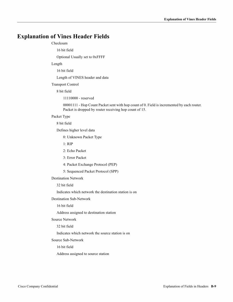
Explanation of Vines Header Fields
Explanation of Vines Header FieldsChecksum
16 bit field
Optional Usually set to 0xFFFF
Length
16 bit field
Length of VINES header and data
Transport Control
8 bit field
11110000 - reserved
00001111 - Hop Count Packet sent with hop count of 0. Field is incremented by each router. Packet is dropped by router receiving hop count of 15.
Packet Type
8 bit field
Defines higher level data
0: Unknown Packet Type
1: RIP
2: Echo Packet
3: Error Packet
4: Packet Exchange Protocol (PEP)
5: Sequenced Packet Protocol (SPP)
Destination Network
32 bit field
Indicates which network the destination station is on
Destination Sub-Network
16 bit field
Address assigned to destination station
Source Network
32 bit field
Indicates which network the source station is on
Source Sub-Network
16 bit field
Address assigned to source station
Cisco Company Confidential Explanation of Fields in Headers B-9
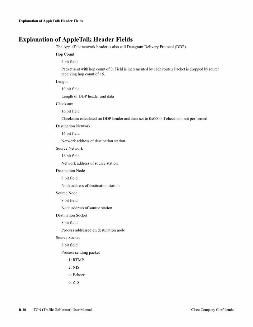
Explanation of AppleTalk Header Fields
Explanation of AppleTalk Header FieldsThe AppleTalk network header is also call Datagram Delivery Protocol (DDP).
Hop Count
4 bit field
Packet sent with hop count of 0. Field is incremented by each route.r Packet is dropped by router receiving hop count of 15.
Length
10 bit field
Length of DDP header and data
Checksum
16 bit field
Checksum calculated on DDP header and data set to 0x0000 if checksum not performed
Destination Network
16 bit field
Network address of destination station
Source Network
16 bit field
Network address of source station
Destination Node
8 bit field
Node address of destination station
Source Node
8 bit field
Node address of source station
Destination Socket
8 bit field
Process addressed on destination node
Source Socket
8 bit field
Process sending packet
1: RTMP
2: NIS
4: Echoer
6: ZIS
TGN (Traffic GeNerator) User Manual Cisco Company ConfidentialB-10
Explanation of DECnet Header Fields
Type
8 bit field
Identification of higher level data
1: RTMP Response or Data
2: NBP
3: ATP
4: AEP
5: RTMP Request
6: ZIP
7: ADSP
Explanation of DECnet Header FieldsLength
16 bit field
Length of DECnet header plus data
Flag
8 bit field
1000 0000: Padding
0100 0000: Version
0010 0000: Intra-Ethernet Packet
0001 0000: Return packet
0000 1000: Do not return to sender
0000 0110: Packet Type: Long Data Packet
0000 0001: Control packet
Dest Area
8 bit field
Not used Keep at 0
Dest SubArea
8 bit field
Not used Keep at 0
Dest Address
48 bit field
MAC address of Destination station Station area and node are encoded in the MAC address
Source Area
8 bit field
Not used Keep at 0
Cisco Company Confidential Explanation of Fields in Headers B-11
Explanation of CLNS Header Fields
Source SubArea
8 bit field
Not used Keep at 0
Source Address
48 bit field
MAC address of Source station Station area and node are encoded in the MAC address
NL2
8 bit field
Next Level Router
Visits
8 bit field
The number of routers the packet has passed through
Class
8 bit field
Service Class Not used Keep at 0
Protocol
8 bit field
Protocol Type Not used Keep at 0
Explanation of CLNS Header FieldsID
8 bit field
Format of this OSI header. The format of the rest of this header is for a data packet; hello packets have different formats.
129: Data Packet
130: End System Hello
131: Intermediate System Hello
Header Length
8 bit field
Length of this header in bytes
Version
8 bit field
Version of header format; current version in use is 1
Lifetime
8 bit field
Remaining life time of packet in 1/2 seconds. Sets how long a packet can exist on the Internet before it is dropped.
TGN (Traffic GeNerator) User Manual Cisco Company ConfidentialB-12
Explanation of CLNS Header Fields
Flags
8 bit field
10000000: SP = Segmentation permitted
01000000: MS = More segments
00100000: E/R = Error Report Requested
00011111: Type = Packet Type
00011100: Data Packet
00000001: Error Packet
Segment Length
16 bit field
Length of Header and data
Checksum
16 bit field
Checksum on Header. If checksum not calculated, set to 0x0000.
Destination Length
8 bit field
This the length of the destination address in number of bytes. Normally, the destination address is considered to be a single number. Here it is split into Area, Address, and Protocol, This length covers all three together,
Destination Area
Variable length
This is the area of the destination station
Destination Address
48 bit field
This is the MAC address of the destination station
Destination Protocol
8 bit field
This is the process on the destination station that should receive this packet
Source Length
8 bit field
This the length of the destination address in number of bytes, Normally, the destination address is considered to be a single number. Here it is split into Area, Address, and Protocol. This length covers all three together.
Source Area
Variable length
This is the area of the source station
Cisco Company Confidential Explanation of Fields in Headers B-13
Explanation of IP ARP and Appletalk ARP Header Fields
Source Address
48 bit field
This is the MAC address of the source station
Source Protocol
8 bit field
This is the process on the source station sending the packet
Explanation of IP ARP and Appletalk ARP Header FieldsHardware
16 bit field
Identification of sender media
Protocol
16 bit field
Identification of protocol
IP is 0x0800
Appletalk is 0x809B
Hardware Length
8 bit field
Length of hardware field in bytes, (MAC address) Value is 6
Protocol Length
8 bit field
Length of protocol address field in bytes, (IP or AppleTalk address). Value is 4. For AppleTalk, the first byte is zero, the second and third have the network address, and the forth byte has the node address.
Operation
16 bit field
Purpose of this ARP packet
1 = Request
2 = Reply
Sender Hardware Address
48 bit field
MAC address of the station sending the packet. Holds the requested information in reply.
Sender Protocol Address
32 bit field
IP or Appletalk address of the station sending the packet
TGN (Traffic GeNerator) User Manual Cisco Company ConfidentialB-14
Explanation of IP ARP and Appletalk ARP Header Fields
Target Hardware Address
48 bit field
MAC address of the destination station. Is zero in request.
Target Protocol Address
32 bit field
IP or AppleTalk address of destination station
Cisco Company Confidential Explanation of Fields in Headers B-15

Explanation of IP ARP and Appletalk ARP Header Fields
TGN (Traffic GeNerator) User Manual Cisco Company ConfidentialB-16