tg96 - design of pipe anchorages - sawater - home · pdf filetable 3.1 - allowable horizontal...
TRANSCRIPT

SOUTH AUSTRALIAN WATER CORPORATION
TECHNICAL GUIDELINE Issued by: Issue Date:
GUIDELINES FOR THE DESIGN OFANCHORS AND THRUST BLOCKS ON
BURIED PIPELINES WITHUNRESTRAINED FLEXIBLE JOINTS
ANCHORAGE OF PIPES ON STEEP GRADES
SOUTH AUSTRALIAN WATER CORPORATION
GUIDELINE
Manager Engineering
10 May 2007
TG
GUIDELINES FOR THE DESIGN OFANCHORS AND THRUST BLOCKS ON
BURIED PIPELINES WITH UNRESTRAINED FLEXIBLE JOINTS
AND FOR THE ANCHORAGE OF PIPES ON STEEP GRADES
TG 96
GUIDELINES FOR THE DESIGN OF ANCHORS AND THRUST BLOCKS ON
UNRESTRAINED FLEXIBLE JOINTS
ANCHORAGE OF PIPES ON STEEP GRADES
PLANNING & INFRASTRUCTURE
TG96 - Design of Pipe Anchorages.docx
Issued by
© SA Water 2007
This document is copyright and all rights are reserved by SA Water. No part may
be reproduced, copied or transmitted in any form or by any means without the
express written permission of SA Water.
The information contained in these Guidelines is strictly for the private use of the
intended recipient in relation to works or projects of SA Water.
These Guidelines have been prepared for SA Water’s own internal use and SA
Water makes no representation as to the quality, accuracy or suitability of the
information for any other purpose.
It is the responsibility of the users of these Guidelines to ensure that the
application of information is appropriate and that any designs based on these
Guidelines are fit for SA Water’s purposes and comply with all relevant Australian
Standards, Acts an
responsibility for interpretation and use of the information contained in these
Guidelines.
SA Water and its officers accept no liability for any loss or damage caused by
reliance on these Guidelines wh
misstatement, misinterpretation or negligence of SA Water.
Users should independently verify the accuracy, fitness for purpose and
application of information contained in these Guidelines.
The currency of the
Major Changes Incorporated In
1. The following lists the major changes to the
96:Section 2.5
of Disadvantages/Issue in this section.
2. Section 6 –
3. Section 4.2, 4.3, 4.4 & 4.5 numeric value in the formula has been
changed.
Design of Pipe Anchorages.docx
Issued by: Manager Engineering
10 May 2007
Uncontrolled on printing
This document is copyright and all rights are reserved by SA Water. No part may
be reproduced, copied or transmitted in any form or by any means without the
ermission of SA Water.
The information contained in these Guidelines is strictly for the private use of the
intended recipient in relation to works or projects of SA Water.
These Guidelines have been prepared for SA Water’s own internal use and SA
makes no representation as to the quality, accuracy or suitability of the
information for any other purpose.
It is the responsibility of the users of these Guidelines to ensure that the
application of information is appropriate and that any designs based on these
Guidelines are fit for SA Water’s purposes and comply with all relevant Australian
Standards, Acts and regulations. Users of these Guidelines accept sole
responsibility for interpretation and use of the information contained in these
SA Water and its officers accept no liability for any loss or damage caused by
reliance on these Guidelines whether caused by error, omission, misdirection,
misstatement, misinterpretation or negligence of SA Water.
Users should independently verify the accuracy, fitness for purpose and
application of information contained in these Guidelines.
The currency of these Guidelines should be checked prior to use.
Major Changes Incorporated In the May 2007 Editio
The following lists the major changes to the May 2007 edition of TG
Section 2.5 - Restrained Joints, additional dot point, plus the inclusion
antages/Issue in this section.
– Corrosion Requirements, changes made to paragraph 6.2
Section 4.2, 4.3, 4.4 & 4.5 numeric value in the formula has been
10 May 2007
Uncontrolled on printing
Page
2 of 26
This document is copyright and all rights are reserved by SA Water. No part may
be reproduced, copied or transmitted in any form or by any means without the
The information contained in these Guidelines is strictly for the private use of the
intended recipient in relation to works or projects of SA Water.
These Guidelines have been prepared for SA Water’s own internal use and SA
makes no representation as to the quality, accuracy or suitability of the
It is the responsibility of the users of these Guidelines to ensure that the
application of information is appropriate and that any designs based on these
Guidelines are fit for SA Water’s purposes and comply with all relevant Australian
d regulations. Users of these Guidelines accept sole
responsibility for interpretation and use of the information contained in these
SA Water and its officers accept no liability for any loss or damage caused by
ether caused by error, omission, misdirection,
Users should independently verify the accuracy, fitness for purpose and
se Guidelines should be checked prior to use.
Edition
May 2007 edition of TG
Restrained Joints, additional dot point, plus the inclusion
Corrosion Requirements, changes made to paragraph 6.2.
Section 4.2, 4.3, 4.4 & 4.5 numeric value in the formula has been

PLANNING & INFRASTRUCTURE
TG96 - Design of Pipe Anchorages.docx
Issued by
Contents
© SA WATER 2007 ................................
MAJOR CHANGES INCORPORATED IN THE MAY 20
SECTION 1: SCOPE ................................
SECTION 2: DEFINITIONS ................................
2.1 UNRESTRAINED FLEXIBLE JOINT
2.2 PIPE SPECIAL ................................
2.3 ANCHOR BLOCK ................................
2.4 THRUST BLOCK ................................
2.5 RESTRAINED JOINTS
SECTION 3: GEOTECHNICAL
3.1 GEOTECHNICAL DESIGN PRINCIPLES
3.2 GEOTECHNICAL ASSESSMENT OF EACH LOCATION
3.3 CONSTRAINTS ON ANCHOR AND THRUST BLOCK LOCATION
3.4 ALLOWABLE HORIZONTAL BEARING PRESSURES
SECTION 4: DESIGN OF ANCHORS & THRUST B
4.1 DESIGN HEAD ................................
4.2 THRUST BLOCKS AT BENDS
4.3 THRUST BLOCKS AT TEES AND DEAD ENDS
4.4 ANCHOR BLOCKS AT TAPERS AND REDUCERS
4.5 ANCHOR BLOCKS AT VALVES AND TEMPORARY DEAD ENDS
4.6 PREPARATION OF DRAWINGS FOR ANCHORS AND THRUST BLOCKS
SECTION 5: THRUST COLLARS AND PUDDLE
5.1 THRUST COLLARS AT ANCHORS ON MSCL PIPELINES
5.2 PUDDLE FLANGES AT ANCHORS ON DICL PIPELINES
SECTION 6: CORROSION REQUIREMENTS
Design of Pipe Anchorages.docx
Issued by: Manager Engineering
10 May 2007
Uncontrolled on printing
................................................................................................
ORATED IN THE MAY 2007 EDITION ................................
................................................................................................
................................................................................................
UNRESTRAINED FLEXIBLE JOINT ................................................................
................................................................................................
................................................................................................
................................................................................................
RESTRAINED JOINTS ...............................................................................................
3: GEOTECHNICAL ............................................................................................
GEOTECHNICAL DESIGN PRINCIPLES ................................................................
GEOTECHNICAL ASSESSMENT OF EACH LOCATION ................................
CONSTRAINTS ON ANCHOR AND THRUST BLOCK LOCATION ...........................
ALLOWABLE HORIZONTAL BEARING PRESSURES ................................
F ANCHORS & THRUST BLOCKS ................................
................................................................................................
THRUST BLOCKS AT BENDS ................................................................
THRUST BLOCKS AT TEES AND DEAD ENDS ................................
ANCHOR BLOCKS AT TAPERS AND REDUCERS ................................
ANCHOR BLOCKS AT VALVES AND TEMPORARY DEAD ENDS
PREPARATION OF DRAWINGS FOR ANCHORS AND THRUST BLOCKS
OLLARS AND PUDDLE FLANGES ................................
THRUST COLLARS AT ANCHORS ON MSCL PIPELINES ................................
PUDDLE FLANGES AT ANCHORS ON DICL PIPELINES ................................
N REQUIREMENTS ................................................................
10 May 2007
Uncontrolled on printing
Page
3 of 26
............................................... 2
................................... 2
............................................ 5
.................................. 5
........................................... 5
........................................... 6
....................................... 6
........................................ 6
............................... 7
............................ 8
................................... 9
........................................... 9
...........................10
..............................................10
..............................................13
..........................................13
..................................................13
.......................................................14
..................................................15
..........................16
PREPARATION OF DRAWINGS FOR ANCHORS AND THRUST BLOCKS .............17
.............................................18
......................................18
........................................18
....................................18

PLANNING & INFRASTRUCTURE
TG96 - Design of Pipe Anchorages.docx
Issued by
6.1 CORROSION REQUIREMENTS ON MSCL PIPE SPECIALS
6.2 CORROSION REQUIREMENTS ON DICL PUDDLE FLANGES
SECTION 7: PIPE ANCHORAGE ON STEEP GRAD
7.1 PIPE ANCHORAGE ON GRADES LESS THAN 20%
7.2 PIPE ANCHORAGE ON GRADES BETWEEN 20% AND 25%
7.3 PIPE ANCHORAGE ON GRADES STEEPER THAN 25%
APPENDIX A: DRAWINGS................................
Tables & Figures
Table 3.1 - Allowable Horizontal Bearing Pressures for Anchors and Thrust Blocks.
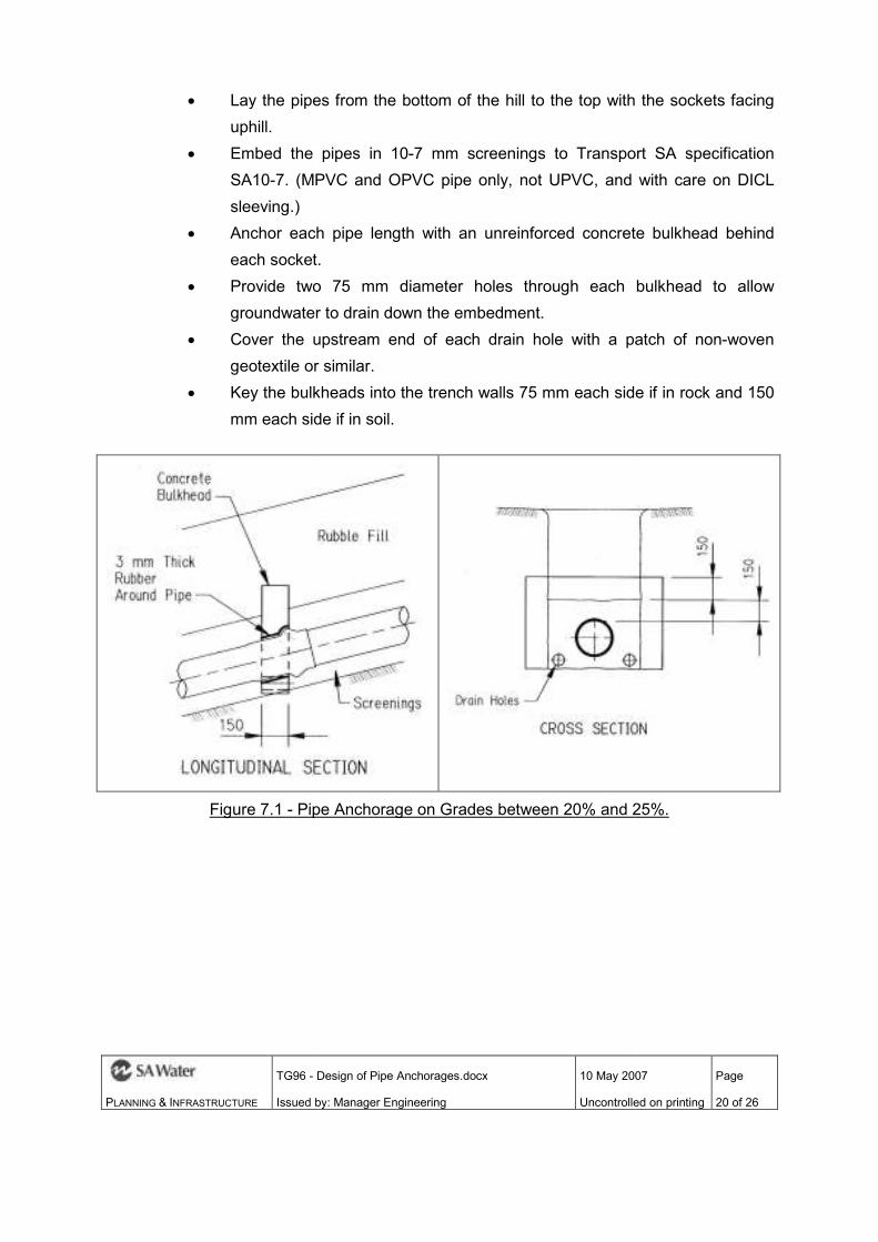
Figure 7.1 - Pipe Anchorage on Grades between 20% and 25%.
Figure 7.2 Pipe Anchorage on Grades Steeper than 25%.
Figure 7.3 - Pipe Anchorage on Grades Steeper than 25%.
Referenced Documents
TS 4b
TS 81
Standard Drawing 75 2A
Drawing 98-0021-01
Transport SA specification SA10
Design of Pipe Anchorages.docx
Issued by: Manager Engineering
10 May 2007
Uncontrolled on printing
CORROSION REQUIREMENTS ON MSCL PIPE SPECIALS ................................
CORROSION REQUIREMENTS ON DICL PUDDLE FLANGES ...............................
HORAGE ON STEEP GRADE ................................
PIPE ANCHORAGE ON GRADES LESS THAN 20% ................................
PIPE ANCHORAGE ON GRADES BETWEEN 20% AND 25% ................................
PIPE ANCHORAGE ON GRADES STEEPER THAN 25% ................................
................................................................................................
Allowable Horizontal Bearing Pressures for Anchors and Thrust Blocks.
Pipe Anchorage on Grades between 20% and 25%. ................................
Figure 7.2 Pipe Anchorage on Grades Steeper than 25%. ................................
Pipe Anchorage on Grades Steeper than 25%. ................................
Referenced Documents
Transport SA specification SA10-7
10 May 2007
Uncontrolled on printing
Page
4 of 26
...................................18
...............................19
......................................................19
................................................19
.................................19
........................................21
.................................24
Allowable Horizontal Bearing Pressures for Anchors and Thrust Blocks. ............11
.........................................20
...................................................22
.................................................23

PLANNING & INFRASTRUCTURE
TG96 - Design of Pipe Anchorages.docx
Issued by
Section 1: Scope
This document outlines the general requirements, as currently preferred by SA
Water, for the design of
pipelines with unrestrained flexible joints.
Also covered are the requirements for the anchorage of buried pipelines with
unrestrained flexible joints when they are laid on steep grades.
This document does not provide guidance for situations where soil conditions or
site constraints are such that
required on buried pipelines with unrestrained flexible joints. These will require
individual engineering inve
circumstances.
Nor does it provide guidance for the design of anchors or thrust blocks for buried
rigid pipelines (where temperature forces might need to be accommodated), or
for any type of aboveground pipelin
Section 2: Definitions
2.1 UNRESTRAINED FLEXIBL
The typical “unrestrained flexible joint” used on SA Water pipelines is a spigot
and socket joint that includes a captive compressed rubber ring in the joint to
prevent leakage. It is therefor
rubber ring joint of this construction has no significant ability to resist being pulled
apart – hence the term “unrestrained”.
Rubber ring joints are also usually designed with the socket somewhat larg
than is absolutely necessary to enable the joint to be assembled. This allows the
joint to be flexed a little after assembly, or even laid with a small permanent
Design of Pipe Anchorages.docx
Issued by: Manager Engineering
10 May 2007
Uncontrolled on printing
This document outlines the general requirements, as currently preferred by SA
Water, for the design of conventional anchor blocks and thrust blocks on buried
pipelines with unrestrained flexible joints.
Also covered are the requirements for the anchorage of buried pipelines with
unrestrained flexible joints when they are laid on steep grades.
nt does not provide guidance for situations where soil conditions or
site constraints are such that non-conventional anchors or thrust blocks are
required on buried pipelines with unrestrained flexible joints. These will require
individual engineering investigation and design to suit the particular
Nor does it provide guidance for the design of anchors or thrust blocks for buried
pipelines (where temperature forces might need to be accommodated), or
for any type of aboveground pipeline.
Section 2: Definitions
UNRESTRAINED FLEXIBLE JOINT
The typical “unrestrained flexible joint” used on SA Water pipelines is a spigot
and socket joint that includes a captive compressed rubber ring in the joint to
prevent leakage. It is therefore known as a “rubber ring joint” or “RRJ”. Clearly a
rubber ring joint of this construction has no significant ability to resist being pulled
hence the term “unrestrained”.
Rubber ring joints are also usually designed with the socket somewhat larg
than is absolutely necessary to enable the joint to be assembled. This allows the
joint to be flexed a little after assembly, or even laid with a small permanent
10 May 2007
Uncontrolled on printing
Page
5 of 26
This document outlines the general requirements, as currently preferred by SA
anchor blocks and thrust blocks on buried
Also covered are the requirements for the anchorage of buried pipelines with
unrestrained flexible joints when they are laid on steep grades.
nt does not provide guidance for situations where soil conditions or
anchors or thrust blocks are
required on buried pipelines with unrestrained flexible joints. These will require
stigation and design to suit the particular
Nor does it provide guidance for the design of anchors or thrust blocks for buried
pipelines (where temperature forces might need to be accommodated), or
The typical “unrestrained flexible joint” used on SA Water pipelines is a spigot
and socket joint that includes a captive compressed rubber ring in the joint to
e known as a “rubber ring joint” or “RRJ”. Clearly a
rubber ring joint of this construction has no significant ability to resist being pulled
Rubber ring joints are also usually designed with the socket somewhat larger
than is absolutely necessary to enable the joint to be assembled. This allows the
joint to be flexed a little after assembly, or even laid with a small permanent
PLANNING & INFRASTRUCTURE
TG96 - Design of Pipe Anchorages.docx
Issued by
angular deflection at each joint so that the pipeline can be made to follow a
gentle curve.
2.2 PIPE SPECIAL
A pipe special is any specially fabricated or precast piece of pipe. In the context
of anchor and thrust block design, a pipe special will usually be a bend, taper,
tee, stop end, or a flanged length of pipe bolted to a valve.
On a pipeline with unrestrained flexible joints, a pipe special will normally need to
be restrained using an anchor or a thrust block.
2.3 ANCHOR BLOCK
A conventional anchor block
a straight piece of pipe, and which is designed to restrain the pipe against
longitudinal movement. Refer to Drawing 98
The longitudinal thrust from the pipe is transferred into the anchor bloc
puddle flange clamped onto the pipe (for DICL pipes) or via a thrust collar welded
to the pipe (for MSCL pipes).
The anchor block is cast into slots cut into the trench wall so as to transfer the
thrust into undisturbed native soil.
Anchor blocks will normally only be used at in
possible to use the much simpler “thrust block”.
2.4 THRUST BLOCK
A thrust block is a simple unreinforced block of concrete cast against, rather
than around, the pipe special.
A conventional thrust block at a
block designed to transfer the thrust from the pipe into the undisturbed native soil
Design of Pipe Anchorages.docx
Issued by: Manager Engineering
10 May 2007
Uncontrolled on printing
angular deflection at each joint so that the pipeline can be made to follow a
is any specially fabricated or precast piece of pipe. In the context
of anchor and thrust block design, a pipe special will usually be a bend, taper,
tee, stop end, or a flanged length of pipe bolted to a valve.
peline with unrestrained flexible joints, a pipe special will normally need to
be restrained using an anchor or a thrust block.
ANCHOR BLOCK
anchor block is a reinforced concrete block which is cast around
a straight piece of pipe, and which is designed to restrain the pipe against
longitudinal movement. Refer to Drawing 98-0021-01.
The longitudinal thrust from the pipe is transferred into the anchor bloc
puddle flange clamped onto the pipe (for DICL pipes) or via a thrust collar welded
to the pipe (for MSCL pipes).
The anchor block is cast into slots cut into the trench wall so as to transfer the
thrust into undisturbed native soil.
s will normally only be used at in-line valves or tapers, where it is not
possible to use the much simpler “thrust block”.
is a simple unreinforced block of concrete cast against, rather
than around, the pipe special.
conventional thrust block at a horizontal bend or tee would be a concrete
block designed to transfer the thrust from the pipe into the undisturbed native soil
10 May 2007
Uncontrolled on printing
Page
6 of 26
angular deflection at each joint so that the pipeline can be made to follow a
is any specially fabricated or precast piece of pipe. In the context
of anchor and thrust block design, a pipe special will usually be a bend, taper,
peline with unrestrained flexible joints, a pipe special will normally need to
is a reinforced concrete block which is cast around
a straight piece of pipe, and which is designed to restrain the pipe against
The longitudinal thrust from the pipe is transferred into the anchor block via a
puddle flange clamped onto the pipe (for DICL pipes) or via a thrust collar welded
The anchor block is cast into slots cut into the trench wall so as to transfer the
line valves or tapers, where it is not
is a simple unreinforced block of concrete cast against, rather
would be a concrete
block designed to transfer the thrust from the pipe into the undisturbed native soil

PLANNING & INFRASTRUCTURE
TG96 - Design of Pipe Anchorages.docx
Issued by
in the trench wall.
A conventional thrust block at a
to that for a horizontal bend, but would bear on the trench floor rather than the
wall.
A conventional thrust block at a
concrete attached to the pipe with sufficient weight to counterbalance the t
Note that an anchor block can be used instead of a thrust block. For example, the
branch of a tee could be extended and an anchor placed on the branch, or both
legs of a bend could be extended and an anchor placed on each leg. But
because of the ex
blocks where conditions at the bend precluded the use of a thrust block there
conflict with other services, weak natural soils, disturbed soils, or the presence of
cross trenches.
2.5 RESTRAINED JOINTS
A “restrained joint” is a usually conventional flexible rubber ring joint that is
restrained against pullout and angular deflection by the inclusion of a
(proprietary) metal
system used on Tyton Ductile Iron pipes.
RRJ Ductile Iron C
for pipes in the size range of 100 to 300 mm nominal diameter.
do not work in comp
Restrained joints can be used
anchorage system
they can be used in association with concrete anchor
Some of the benefi
are:
• No concrete is required. This is convenient in areas where the logistics of
providing concrete is difficult.
Design of Pipe Anchorages.docx
Issued by: Manager Engineering
10 May 2007
Uncontrolled on printing
in the trench wall.
A conventional thrust block at a vertical bend (downward thrust) would be s
to that for a horizontal bend, but would bear on the trench floor rather than the
A conventional thrust block at a vertical bend (upward thrust) is simply a block of
concrete attached to the pipe with sufficient weight to counterbalance the t
Note that an anchor block can be used instead of a thrust block. For example, the
branch of a tee could be extended and an anchor placed on the branch, or both
legs of a bend could be extended and an anchor placed on each leg. But
because of the extra cost, anchor blocks would only be used instead of thrust
blocks where conditions at the bend precluded the use of a thrust block there
conflict with other services, weak natural soils, disturbed soils, or the presence of
AINED JOINTS
A “restrained joint” is a usually conventional flexible rubber ring joint that is
restrained against pullout and angular deflection by the inclusion of a
metal “claw” device in the rubber ring. An example is the Tyton
used on Tyton Ductile Iron pipes. Restrained joints are available only for
Cement (mortar) Lined (DICL) pipes and fittings, and then only
for pipes in the size range of 100 to 300 mm nominal diameter.
do not work in compression.
Restrained joints can be used either to create a complete
anchorage system” (as an alternative to concrete anchors or
they can be used in association with concrete anchors or thrust blocks.
Some of the benefits of restrained joint anchorage systems on
No concrete is required. This is convenient in areas where the logistics of
providing concrete is difficult.
10 May 2007
Uncontrolled on printing
Page
7 of 26
(downward thrust) would be similar
to that for a horizontal bend, but would bear on the trench floor rather than the
(upward thrust) is simply a block of
concrete attached to the pipe with sufficient weight to counterbalance the thrust.
Note that an anchor block can be used instead of a thrust block. For example, the
branch of a tee could be extended and an anchor placed on the branch, or both
legs of a bend could be extended and an anchor placed on each leg. But
tra cost, anchor blocks would only be used instead of thrust
blocks where conditions at the bend precluded the use of a thrust block there - eg
conflict with other services, weak natural soils, disturbed soils, or the presence of
A “restrained joint” is a usually conventional flexible rubber ring joint that is
restrained against pullout and angular deflection by the inclusion of a
“claw” device in the rubber ring. An example is the Tyton-Lok
are available only for
) pipes and fittings, and then only
for pipes in the size range of 100 to 300 mm nominal diameter. Restrained joints
to create a complete “restrained joint
or thrust blocks) or
or thrust blocks.
systems on DICL pipelines
No concrete is required. This is convenient in areas where the logistics of

PLANNING & INFRASTRUCTURE
TG96 - Design of Pipe Anchorages.docx
Issued by
• They occupy no space outside of the pipe trench. This is convenient where
space is at a premium in congested service corridors, or where future
interference by other utilities can be anticipated.
• The pipeline can be pressure tested and put into service immediately
curing time is required for concrete anchors or thrust blocks. This i
convenient when the commissioning of the pipeline is urgent.
• A “complete system
conventional concrete anchors or thrust blocks where there is no
satisfactory ground within a reasonable distance.
• A “short run
conventional concrete anchors or thrust blocks. This might be useful for
example where the ground at the desired location is unsatisfactory but
there is good ground a short distance away, or where othe
services would otherwise be in the thrust zone of an anchor or thrust block.
• Manufacturers can specify a minimum length
joints to provide restraint for a tee or bend etc.
Disadvantages/Issues
• Cut-ins difficult
• Must be marked as restrained to prevent incorrect repair procedure.
• Locking gasket may only be used in pipe recommended by manufacturer.
Incompatibility problems.
Restrained joint anchorage system design software is available from some
manufacturers, but
to follow conventional geotechnical or structural engineering principles rigorously.
Because of this, and because most manufacturers offer a free design service for
complete restrained joint an
usually come with a warranty, it is recommended that in general a manufacturer’s
design be requested and adopted.
Section 3: Geotechnical
Design of Pipe Anchorages.docx
Issued by: Manager Engineering
10 May 2007
Uncontrolled on printing
They occupy no space outside of the pipe trench. This is convenient where
at a premium in congested service corridors, or where future
interference by other utilities can be anticipated.
The pipeline can be pressure tested and put into service immediately
curing time is required for concrete anchors or thrust blocks. This i
convenient when the commissioning of the pipeline is urgent.
complete system” of restrained joints can be used
conventional concrete anchors or thrust blocks where there is no
satisfactory ground within a reasonable distance.
A “short run” of restrained joints can be used in association with
conventional concrete anchors or thrust blocks. This might be useful for
example where the ground at the desired location is unsatisfactory but
there is good ground a short distance away, or where othe
services would otherwise be in the thrust zone of an anchor or thrust block.
Manufacturers can specify a minimum length of buried pipe with restrained
joints to provide restraint for a tee or bend etc.
Disadvantages/Issues
ins difficult
Must be marked as restrained to prevent incorrect repair procedure.
Locking gasket may only be used in pipe recommended by manufacturer.
Incompatibility problems.
Restrained joint anchorage system design software is available from some
manufacturers, but the design models used in that software do not always appear
to follow conventional geotechnical or structural engineering principles rigorously.
Because of this, and because most manufacturers offer a free design service for
complete restrained joint anchorage systems, and also because such designs
usually come with a warranty, it is recommended that in general a manufacturer’s
design be requested and adopted.
Section 3: Geotechnical
10 May 2007
Uncontrolled on printing
Page
8 of 26
They occupy no space outside of the pipe trench. This is convenient where
at a premium in congested service corridors, or where future
The pipeline can be pressure tested and put into service immediately – no
curing time is required for concrete anchors or thrust blocks. This is
convenient when the commissioning of the pipeline is urgent.
” of restrained joints can be used instead of
conventional concrete anchors or thrust blocks where there is no
in association with
conventional concrete anchors or thrust blocks. This might be useful for
example where the ground at the desired location is unsatisfactory but
there is good ground a short distance away, or where other trenches or
services would otherwise be in the thrust zone of an anchor or thrust block.
of buried pipe with restrained
Must be marked as restrained to prevent incorrect repair procedure.
Locking gasket may only be used in pipe recommended by manufacturer.
Restrained joint anchorage system design software is available from some
the design models used in that software do not always appear
to follow conventional geotechnical or structural engineering principles rigorously.
Because of this, and because most manufacturers offer a free design service for
chorage systems, and also because such designs
usually come with a warranty, it is recommended that in general a manufacturer’s

PLANNING & INFRASTRUCTURE
TG96 - Design of Pipe Anchorages.docx
Issued by
3.1 GEOTECHNICAL DESIGN
An anchor or thrust block must
ONLY into the undisturbed native soil in the trench wall. On no account should
the pipe embedment be relied upon to resist any of the thrust. There are three
main reasons for this:
(1) It is generally impo
material) sufficiently densely against an anchor or thrust block to eliminate
any bedding
can easily be 5
movement.)
(2) It is possible that the trench fill material will not have been placed when the
pressure test is carried out. If so, the pipe embedment material would have
no surcharge load on it and therefore could not resist any horizontal
(3) The natural material is likely to have a much higher stiffness modulus than
the embedment material, and will therefore attract most of the thrust
anyway.
The designer should also be aware that in most pipe networks it is likely that the
thrust on a valve etc could come from either direction. The designer should
therefore specify that BOTH faces of an anchor block must be poured against
undisturbed native soil.
3.2 GEOTECHNICAL ASSESSM
Soil conditions, particularly at the s
blocks are usually set, can vary enormously over short distances, as a study of
almost any road cutting or trench wall will reveal.
Design of Pipe Anchorages.docx
Issued by: Manager Engineering
10 May 2007
Uncontrolled on printing
GEOTECHNICAL DESIGN PRINCIPLES
An anchor or thrust block must be designed to transfer the thrust from the pipe
ONLY into the undisturbed native soil in the trench wall. On no account should
the pipe embedment be relied upon to resist any of the thrust. There are three
main reasons for this:
It is generally impossible to compact embedment material (or any other
material) sufficiently densely against an anchor or thrust block to eliminate
any bedding-in movement. (Trials have shown that bedding
can easily be 5 mm or so, which may be half of the total p
It is possible that the trench fill material will not have been placed when the
pressure test is carried out. If so, the pipe embedment material would have
no surcharge load on it and therefore could not resist any horizontal
The natural material is likely to have a much higher stiffness modulus than
the embedment material, and will therefore attract most of the thrust
The designer should also be aware that in most pipe networks it is likely that the
on a valve etc could come from either direction. The designer should
therefore specify that BOTH faces of an anchor block must be poured against
undisturbed native soil.
GEOTECHNICAL ASSESSMENT OF EACH LOCATION
Soil conditions, particularly at the shallow depths at which anchors and thrust
blocks are usually set, can vary enormously over short distances, as a study of
almost any road cutting or trench wall will reveal.
10 May 2007
Uncontrolled on printing
Page
9 of 26
be designed to transfer the thrust from the pipe
ONLY into the undisturbed native soil in the trench wall. On no account should
the pipe embedment be relied upon to resist any of the thrust. There are three
ssible to compact embedment material (or any other
material) sufficiently densely against an anchor or thrust block to eliminate
in movement. (Trials have shown that bedding-in movement
mm or so, which may be half of the total permissible
It is possible that the trench fill material will not have been placed when the
pressure test is carried out. If so, the pipe embedment material would have
no surcharge load on it and therefore could not resist any horizontal force.
The natural material is likely to have a much higher stiffness modulus than
the embedment material, and will therefore attract most of the thrust
The designer should also be aware that in most pipe networks it is likely that the
on a valve etc could come from either direction. The designer should
therefore specify that BOTH faces of an anchor block must be poured against
hallow depths at which anchors and thrust
blocks are usually set, can vary enormously over short distances, as a study of

PLANNING & INFRASTRUCTURE
TG96 - Design of Pipe Anchorages.docx
Issued by
The designer will therefore need to ascertain the allowable horizontal (or vert
bearing capacity of the natural ground at each anchor or thrust block location.
In some areas this will mean an investigation of the exact location of each anchor
or thrust block prior to commencing the design.
In other areas (eg the Adelaide metro
experience is gained in an area, to adopt a conservative design value for that
area. Even so, each anchor or thrust block location should be checked by a
trained person to ensure that the conditions are as assumed
3.3 CONSTRAINTS ON ANCHO
The designer should be aware that the proposed location of an anchor or thrust
block might have other pipe or service trenches or other excavations close to it. If
these trenches or excavations, whet
ground stressed by the bearing area of the anchor or thrust block, then they may
compromise the effectiveness of the proposed block to resist the thrust without
exceeding the allowable movement.
In such circumstances, it may be necessary to design the pipe special so that the
anchor or thrust block is located well away from any cross trenches or other
excavated areas or disturbed ground (eg by extending one leg or otherwise
changing the configuration of the sp
mm diameter, restrained joints may be used (Refer Section
3.4 ALLOWABLE HORIZONTAL
The purpose of an anchor or thrust block is not simply to resist the force from the
fitting, but for it to do so without the
allowable movement
rubber ring joint on a 150 mm pipe may only be able to tolerate an extension of
less than 10 mm.
The soil on which th
Design of Pipe Anchorages.docx
Issued by: Manager Engineering
10 May 2007
Uncontrolled on printing
The designer will therefore need to ascertain the allowable horizontal (or vert
bearing capacity of the natural ground at each anchor or thrust block location.
In some areas this will mean an investigation of the exact location of each anchor
or thrust block prior to commencing the design.
In other areas (eg the Adelaide metro area) it may be possible, once sufficient
experience is gained in an area, to adopt a conservative design value for that
area. Even so, each anchor or thrust block location should be checked by a
trained person to ensure that the conditions are as assumed.
CONSTRAINTS ON ANCHOR AND THRUST BLOCK LOCATION
The designer should be aware that the proposed location of an anchor or thrust
block might have other pipe or service trenches or other excavations close to it. If
these trenches or excavations, whether open or backfilled, are within the zone of
ground stressed by the bearing area of the anchor or thrust block, then they may
compromise the effectiveness of the proposed block to resist the thrust without
exceeding the allowable movement.
mstances, it may be necessary to design the pipe special so that the
anchor or thrust block is located well away from any cross trenches or other
excavated areas or disturbed ground (eg by extending one leg or otherwise
changing the configuration of the special). Alternatively, for DICL pipes up to 300
mm diameter, restrained joints may be used (Refer Section 2.5
ALLOWABLE HORIZONTAL BEARING PRESSURES
The purpose of an anchor or thrust block is not simply to resist the force from the
or it to do so without the movement of the block exceeding the
allowable movement at the pipe joints closest to the block. For example, a
rubber ring joint on a 150 mm pipe may only be able to tolerate an extension of
The soil on which the block is bearing must therefore be judged not by its
10 May 2007
Uncontrolled on printing
Page
10 of 26
The designer will therefore need to ascertain the allowable horizontal (or vertical)
bearing capacity of the natural ground at each anchor or thrust block location.
In some areas this will mean an investigation of the exact location of each anchor
area) it may be possible, once sufficient
experience is gained in an area, to adopt a conservative design value for that
area. Even so, each anchor or thrust block location should be checked by a
OCATION
The designer should be aware that the proposed location of an anchor or thrust
block might have other pipe or service trenches or other excavations close to it. If
her open or backfilled, are within the zone of
ground stressed by the bearing area of the anchor or thrust block, then they may
compromise the effectiveness of the proposed block to resist the thrust without
mstances, it may be necessary to design the pipe special so that the
anchor or thrust block is located well away from any cross trenches or other
excavated areas or disturbed ground (eg by extending one leg or otherwise
ecial). Alternatively, for DICL pipes up to 300
2.5).
The purpose of an anchor or thrust block is not simply to resist the force from the
of the block exceeding the
at the pipe joints closest to the block. For example, a
rubber ring joint on a 150 mm pipe may only be able to tolerate an extension of
e block is bearing must therefore be judged not by its

PLANNING & INFRASTRUCTURE
TG96 - Design of Pipe Anchorages.docx
Issued by
ultimate horizontal bearing capacity at “failure”, but by its load
characteristics well below the failure stress. Note that the load
characteristics of a soil are governed not so
a clay or a sandy soil) but by its density (if a sand) or its consistency (if a clay).
The assessment of the allowable horizontal bearing pressure clearly requires a
geotechnical investigation at the exact location and considerable geotechnical
experience. However, where ground conditions are reasonably good, and the
thrusts are not large (e
reasonable to use simple field identification tests, and to adopt conservative
values for allowable horizontal bearing pressures. Examples of some simple field
identification tests and conservative allow
given in Table 1.
Note that for larger pipes (above 300 mm diameter) adopting a conservative
value is likely to result in a very large anchor or thrust block, and so it is likely to
prove more economical to investiga
It is clear from the foregoing discussion that there will be situations where the
ground conditions are so poor that the
any reasonably sized
scope of these guidelines to detail other options available to designers in such
situations, but mention will be made of a few which could be considered, namely:
(a) Using restrained joint anchorage systems (eg Tyton
(b) Pre-loading an anchor or thrust block using jacks (can only work in one
direction).
(c) Using piles or piers.
(d) Using a welded “special” to transfer the thrust to a location where a
conventional anchor or thrust block can be used.
Table 3.1 - Allowable Horizontal Bearing Pressures for Anchors and Thrust Blocks
Trench Wall Material
Design of Pipe Anchorages.docx
Issued by: Manager Engineering
10 May 2007
Uncontrolled on printing
ultimate horizontal bearing capacity at “failure”, but by its load
characteristics well below the failure stress. Note that the load
characteristics of a soil are governed not so much by the soil type (ie whether it is
a clay or a sandy soil) but by its density (if a sand) or its consistency (if a clay).
The assessment of the allowable horizontal bearing pressure clearly requires a
geotechnical investigation at the exact location and considerable geotechnical
experience. However, where ground conditions are reasonably good, and the
thrusts are not large (eg pipe diameter is less than 300 mm), then it may be
reasonable to use simple field identification tests, and to adopt conservative
values for allowable horizontal bearing pressures. Examples of some simple field
identification tests and conservative allowable horizontal bearing pressures are
Note that for larger pipes (above 300 mm diameter) adopting a conservative
value is likely to result in a very large anchor or thrust block, and so it is likely to
prove more economical to investigate the ground conditions at each location.
It is clear from the foregoing discussion that there will be situations where the
ground conditions are so poor that the allowable movement will be exceeded by
any reasonably sized conventional anchor or thrust block. It is not within the
scope of these guidelines to detail other options available to designers in such
situations, but mention will be made of a few which could be considered, namely:
Using restrained joint anchorage systems (eg Tyton-Loc).
loading an anchor or thrust block using jacks (can only work in one
Using piles or piers.
Using a welded “special” to transfer the thrust to a location where a
conventional anchor or thrust block can be used.
Allowable Horizontal Bearing Pressures for Anchors and Thrust Blocks
Trench Wall Material Field Identification Test
(1)
10 May 2007
Uncontrolled on printing
Page
11 of 26
ultimate horizontal bearing capacity at “failure”, but by its load-deflection
characteristics well below the failure stress. Note that the load-deflection
much by the soil type (ie whether it is
a clay or a sandy soil) but by its density (if a sand) or its consistency (if a clay).
The assessment of the allowable horizontal bearing pressure clearly requires a
geotechnical investigation at the exact location and considerable geotechnical
experience. However, where ground conditions are reasonably good, and the
g pipe diameter is less than 300 mm), then it may be
reasonable to use simple field identification tests, and to adopt conservative
values for allowable horizontal bearing pressures. Examples of some simple field
able horizontal bearing pressures are
Note that for larger pipes (above 300 mm diameter) adopting a conservative
value is likely to result in a very large anchor or thrust block, and so it is likely to
te the ground conditions at each location.
It is clear from the foregoing discussion that there will be situations where the
will be exceeded by
lock. It is not within the
scope of these guidelines to detail other options available to designers in such
situations, but mention will be made of a few which could be considered, namely:
Loc).
loading an anchor or thrust block using jacks (can only work in one
Using a welded “special” to transfer the thrust to a location where a
Allowable Horizontal Bearing Pressures for Anchors and Thrust Blocks.
Allowable
Horizontal
Bearing
Pressure (2)

PLANNING & INFRASTRUCTURE
TG96 - Design of Pipe Anchorages.docx
Issued by
CLAYS Very Soft Clay
Soft Clay
Firm Clay
Stiff Clay
Very Stiff Clay
Hard Clay
SANDS Loose Clean Sand
Medium-Dense Clean
Sand
Dense Clean Sand or
Gravel
ROCK
Broken or
Decomposed Rock
Sound Rock
UNCOMPACTED FILL
DOMESTIC REFUSE
(1) All field identification tests must be done on a freshly exposed, damp,
trench wall by an engineer / technical officer competent in such work. Care must be taken to
ensure that the soil in the test area was not compacted or loosened during the excavation. If the
soil in the trench floor is very dry at
and time allowed for the water to be absorbed by the soil before trimming and testing.
(2) For anchors and thrust blocks with the centre of thrust about 1 m below the surface as occurs
with SA Water reticulation systems where normal cover to the pipe is 750 mm.
Design of Pipe Anchorages.docx
Issued by: Manager Engineering
10 May 2007
Uncontrolled on printing
Very Soft Clay Easily penetrated 40 mm with fist
Soft Clay Easily penetrated 40 mm with thumb
Firm Clay Moderate effort needed to penetrate
30 mm with thumb
Stiff Clay Readily indented with thumb but penetrated
only with great effort
Very Stiff Clay Readily indented by thumbnail
Hard Clay Indented with difficulty by thumbnail
Loose Clean Sand Takes footprint more than
10 mm deep
Dense Clean Takes footprint 3 mm to
10 mm deep
Dense Clean Sand or
Takes footprint less than
3 mm deep
Broken or
Decomposed Rock
Can be dug with pick. Hammer blow “thuds”.
Joints spaced less than 300 mm apart.
Sound Rock Too hard to dig with pick. Hammer blow
“rings”. Joints more than 300 mm apart.
UNCOMPACTED FILL
Visual inspection of the materials and/or a
knowledge of the history of the site.
All field identification tests must be done on a freshly exposed, damp, hand
trench wall by an engineer / technical officer competent in such work. Care must be taken to
ensure that the soil in the test area was not compacted or loosened during the excavation. If the
soil in the trench floor is very dry at the time the trench is opened, the test area must be flooded
and time allowed for the water to be absorbed by the soil before trimming and testing.
For anchors and thrust blocks with the centre of thrust about 1 m below the surface as occurs
ater reticulation systems where normal cover to the pipe is 750 mm.
10 May 2007
Uncontrolled on printing
Page
12 of 26
(3)
(3)
(3)
Readily indented with thumb but penetrated 50 kPa
100 kPa
200 kPa
(3)
50 kPa
100 kPa
Can be dug with pick. Hammer blow “thuds”. 100 kPa
200 kPa
Visual inspection of the materials and/or a (3)
hand-trimmed area of the
trench wall by an engineer / technical officer competent in such work. Care must be taken to
ensure that the soil in the test area was not compacted or loosened during the excavation. If the
the time the trench is opened, the test area must be flooded
and time allowed for the water to be absorbed by the soil before trimming and testing.
For anchors and thrust blocks with the centre of thrust about 1 m below the surface as occurs
ater reticulation systems where normal cover to the pipe is 750 mm.

PLANNING & INFRASTRUCTURE
TG96 - Design of Pipe Anchorages.docx
Issued by
(3) Standard values cannot be used
Section 4: Design of Anchors & Thrust Blocks
4.1 DESIGN HEAD
The design head for anc
For SA Water reticulation systems the test pressure is 1.6 MPa (160 m head).
For water supply trunk mains, sewer rising mains, irrigation water supply mains,
etc, the test pressure will be
pressure will generally be the operating pressure (including surge allowance)
multiplied by an appropriate factor of safety.
4.2 THRUST BLOCKS AT BEN
Thrust blocks at horizontal and vertical bends on
unrestrained flexible joints are designed to resist the total resultant hydraulic
thrust. It is assumed that the block transmits all of the thrust into the adjacent
native soil or rock only (ie not into the pipe embedment material or
compacted fill).
The thrust block should not protrude beyond the space allocation for the pipeline
when located in a road reserve.
i) For pipelines 100 to 300 mm in diameter, with a test pressure not in excess
of 1.6 MPa (160 m head), thrust blocks
Construction Manual Drawings may be used. Note that the size of the
thrust block in these drawings is determined on the basis that the pipe is
laid at the minimum cover.
ii) For pipelines with test pressures exceeding 1.6
Design of Pipe Anchorages.docx
Issued by: Manager Engineering
10 May 2007
Uncontrolled on printing
Standard values cannot be used - specialist geotechnical investigation and design required.
Section 4: Design of Anchors & Thrust Blocks
The design head for anchor and thrust blocks will generally be the test pressure.
For SA Water reticulation systems the test pressure is 1.6 MPa (160 m head).
For water supply trunk mains, sewer rising mains, irrigation water supply mains,
etc, the test pressure will be determined by the designer of the pipeline. The test
pressure will generally be the operating pressure (including surge allowance)
multiplied by an appropriate factor of safety.
THRUST BLOCKS AT BENDS
Thrust blocks at horizontal and vertical bends on buried pipelines with
unrestrained flexible joints are designed to resist the total resultant hydraulic
thrust. It is assumed that the block transmits all of the thrust into the adjacent
native soil or rock only (ie not into the pipe embedment material or
The thrust block should not protrude beyond the space allocation for the pipeline
when located in a road reserve.
For pipelines 100 to 300 mm in diameter, with a test pressure not in excess
of 1.6 MPa (160 m head), thrust blocks as shown on the appropriate Water
Construction Manual Drawings may be used. Note that the size of the
thrust block in these drawings is determined on the basis that the pipe is
laid at the minimum cover.
For pipelines with test pressures exceeding 1.6 MPa, and all pipelines 375
10 May 2007
Uncontrolled on printing
Page
13 of 26
specialist geotechnical investigation and design required.
hor and thrust blocks will generally be the test pressure.
For SA Water reticulation systems the test pressure is 1.6 MPa (160 m head).
For water supply trunk mains, sewer rising mains, irrigation water supply mains,
determined by the designer of the pipeline. The test
pressure will generally be the operating pressure (including surge allowance)
buried pipelines with
unrestrained flexible joints are designed to resist the total resultant hydraulic
thrust. It is assumed that the block transmits all of the thrust into the adjacent
native soil or rock only (ie not into the pipe embedment material or any
The thrust block should not protrude beyond the space allocation for the pipeline
For pipelines 100 to 300 mm in diameter, with a test pressure not in excess
as shown on the appropriate Water
Construction Manual Drawings may be used. Note that the size of the
thrust block in these drawings is determined on the basis that the pipe is
MPa, and all pipelines 375

PLANNING & INFRASTRUCTURE
TG96 - Design of Pipe Anchorages.docx
Issued by
mm in diameter or greater, the following formula may be used to calculate
the resultant thrust at a bend:
where:
Note that the resultant thrust bisects the angle of the bend. A long lobster
back bend may need to be considered as two separate bends (ie with two
thrust blocks, one at each end) to a
between the ends of the lobster
4.3 THRUST BLOCKS AT TEE
Thrust blocks at tees and dead ends on buried pipelines with unrestrained
flexible joints are designed to resist the total hydraulic thrust.
the thrust block transmits all of the thrust into the adjacent native soil or rock only
(ie not into the pipe embedment material or any compacted fill).
The thrust block should not protrude beyond the space allocation for the pipeline
when located in a road reserve.
i) For pipelines 100 to 300 mm in diameter, with a test pressure not in excess
of 1.6 MPa (160 m head), thrust blocks as shown on the appropriate Water
Construction Manual Drawings may be used. Note that the size of the
thrust blocks in these drawings is dete
laid at minimum cover and with the minimum allowable trench width.
ii) For pipelines with test pressures exceeding 1.6 MPa, and all pipelines 375
mm in diameter and greater, the following formula may be used to calcula
the thrust at a tee or dead end:
Design of Pipe Anchorages.docx
Issued by: Manager Engineering
10 May 2007
Uncontrolled on printing
mm in diameter or greater, the following formula may be used to calculate
the resultant thrust at a bend:
T = 1.54 x 10⁻⁵ x h x d2 x sin (φ / 2)
T = resultant thrust in kN
h = effective head in metres
d = outside diameter of pipe (mm)
φ = deflection angle of bend in degrees
Note that the resultant thrust bisects the angle of the bend. A long lobster
back bend may need to be considered as two separate bends (ie with two
thrust blocks, one at each end) to avoid bending stresses in the pipe
between the ends of the lobster-back.
THRUST BLOCKS AT TEES AND DEAD ENDS
Thrust blocks at tees and dead ends on buried pipelines with unrestrained
flexible joints are designed to resist the total hydraulic thrust.
the thrust block transmits all of the thrust into the adjacent native soil or rock only
(ie not into the pipe embedment material or any compacted fill).
The thrust block should not protrude beyond the space allocation for the pipeline
hen located in a road reserve.
For pipelines 100 to 300 mm in diameter, with a test pressure not in excess
of 1.6 MPa (160 m head), thrust blocks as shown on the appropriate Water
Construction Manual Drawings may be used. Note that the size of the
thrust blocks in these drawings is determined on the basis that the pipe is
laid at minimum cover and with the minimum allowable trench width.
For pipelines with test pressures exceeding 1.6 MPa, and all pipelines 375
mm in diameter and greater, the following formula may be used to calcula
the thrust at a tee or dead end:
10 May 2007
Uncontrolled on printing
Page
14 of 26
mm in diameter or greater, the following formula may be used to calculate
= deflection angle of bend in degrees
Note that the resultant thrust bisects the angle of the bend. A long lobster-
back bend may need to be considered as two separate bends (ie with two
void bending stresses in the pipe
Thrust blocks at tees and dead ends on buried pipelines with unrestrained
flexible joints are designed to resist the total hydraulic thrust. It is assumed that
the thrust block transmits all of the thrust into the adjacent native soil or rock only
(ie not into the pipe embedment material or any compacted fill).
The thrust block should not protrude beyond the space allocation for the pipeline
For pipelines 100 to 300 mm in diameter, with a test pressure not in excess
of 1.6 MPa (160 m head), thrust blocks as shown on the appropriate Water
Construction Manual Drawings may be used. Note that the size of the
rmined on the basis that the pipe is
laid at minimum cover and with the minimum allowable trench width.
For pipelines with test pressures exceeding 1.6 MPa, and all pipelines 375
mm in diameter and greater, the following formula may be used to calculate

PLANNING & INFRASTRUCTURE
TG96 - Design of Pipe Anchorages.docx
Issued by
where:
Note that the thrust acts axially along the line of the branch at a tee, and
axially along the pipe at a dead end.
4.4 ANCHOR BLOCKS AT TAP
Anchor blocks at tapers and reducers on buried pipelines with unrestrained
flexible joints are designed to resist the total hydraulic thrust. It is assumed that
the thrust is transmi
flange (DICL) and then from the anchor block into the adjacent native soil or rock
only (ie never into the pipe embedment material or any compacted fill).
The preferred design model is indicated
Anchor Blocks - Structural Design Requirements.
Design of Pipe Anchorages.docx
Issued by: Manager Engineering
10 May 2007
Uncontrolled on printing
T = 0.77 x 10⁻⁵ x h x d2
T = resultant thrust in kN
h = effective head in metres
d = outside diameter of pipe (mm)
Note that the thrust acts axially along the line of the branch at a tee, and
along the pipe at a dead end.
ANCHOR BLOCKS AT TAPERS AND REDUCERS
Anchor blocks at tapers and reducers on buried pipelines with unrestrained
flexible joints are designed to resist the total hydraulic thrust. It is assumed that
the thrust is transmitted to the anchor block via a thrust ring (MSCL) or puddle
flange (DICL) and then from the anchor block into the adjacent native soil or rock
only (ie never into the pipe embedment material or any compacted fill).
The preferred design model is indicated on Drawing 98-0021
Structural Design Requirements.
10 May 2007
Uncontrolled on printing
Page
15 of 26
Note that the thrust acts axially along the line of the branch at a tee, and
Anchor blocks at tapers and reducers on buried pipelines with unrestrained
flexible joints are designed to resist the total hydraulic thrust. It is assumed that
tted to the anchor block via a thrust ring (MSCL) or puddle
flange (DICL) and then from the anchor block into the adjacent native soil or rock
only (ie never into the pipe embedment material or any compacted fill).
0021-01 - Concrete

PLANNING & INFRASTRUCTURE
TG96 - Design of Pipe Anchorages.docx
Issued by
The anchor block should not protrude beyond the space allocation for the
pipeline when located in a road reserve.
i) For tapers and reducers with the larger diameter between
mm, and with a test pressure not in excess of 1.6 MPa (160 m head), the
anchor blocks shown on the appropriate Water Construction Manual
Drawings may be used. Note that the size of the anchor blocks on these
drawings is determined on the basis
ii) For pipelines with test pressures exceeding 1.6 MPa, and all tapers and
reducers with the larger diameter greater than 375 mm, the following
formula may be used to calculate the thrust:
where:
Note that the thrust always acts axially along the pipe in the direction from
the larger diameter to the smaller irrespective of the direction of flow
(friction forces are neglected).
The anchor is usually located on the larger diameter parallel
the taper or reducer.
4.5 ANCHOR BLOCKS AT VAL
Anchor blocks at valves and temporary dead ends on buried pipelines with
unrestrained flexible joints are designed by assuming that the total thrust is
transmitted to the anchor block via a thrust ring or puddle flange, and then from
the anchor block i
material or any compacted fill.) The preferred design model is indicated on
Drawing 98-0021-
Design of Pipe Anchorages.docx
Issued by: Manager Engineering
10 May 2007
Uncontrolled on printing
The anchor block should not protrude beyond the space allocation for the
pipeline when located in a road reserve.
For tapers and reducers with the larger diameter between
mm, and with a test pressure not in excess of 1.6 MPa (160 m head), the
anchor blocks shown on the appropriate Water Construction Manual
Drawings may be used. Note that the size of the anchor blocks on these
drawings is determined on the basis that the main is laid at minimum cover.
For pipelines with test pressures exceeding 1.6 MPa, and all tapers and
reducers with the larger diameter greater than 375 mm, the following
formula may be used to calculate the thrust:
T = 0.77 x 10⁻⁵ x h x (D2- d2)
T = resultant thrust in kN
h = effective head in metres
D = outside diameter of larger pipe (mm)
d = outside diameter of smaller pipe (mm)
Note that the thrust always acts axially along the pipe in the direction from
larger diameter to the smaller irrespective of the direction of flow
(friction forces are neglected).
The anchor is usually located on the larger diameter parallel
the taper or reducer.
ANCHOR BLOCKS AT VALVES AND TEMPORARY DEAD EN
Anchor blocks at valves and temporary dead ends on buried pipelines with
unrestrained flexible joints are designed by assuming that the total thrust is
transmitted to the anchor block via a thrust ring or puddle flange, and then from
the anchor block into native soil or rock. (Ie never into the pipe embedment
material or any compacted fill.) The preferred design model is indicated on
01.
10 May 2007
Uncontrolled on printing
Page
16 of 26
The anchor block should not protrude beyond the space allocation for the
For tapers and reducers with the larger diameter between 100 and 375
mm, and with a test pressure not in excess of 1.6 MPa (160 m head), the
anchor blocks shown on the appropriate Water Construction Manual
Drawings may be used. Note that the size of the anchor blocks on these
that the main is laid at minimum cover.
For pipelines with test pressures exceeding 1.6 MPa, and all tapers and
reducers with the larger diameter greater than 375 mm, the following
D = outside diameter of larger pipe (mm)
d = outside diameter of smaller pipe (mm)
Note that the thrust always acts axially along the pipe in the direction from
larger diameter to the smaller irrespective of the direction of flow
The anchor is usually located on the larger diameter parallel-wall section of
AD ENDS
Anchor blocks at valves and temporary dead ends on buried pipelines with
unrestrained flexible joints are designed by assuming that the total thrust is
transmitted to the anchor block via a thrust ring or puddle flange, and then from
nto native soil or rock. (Ie never into the pipe embedment
material or any compacted fill.) The preferred design model is indicated on

PLANNING & INFRASTRUCTURE
TG96 - Design of Pipe Anchorages.docx
Issued by
Note that the anchor block should not protrude beyond the space allocation for
the pipeline when loc
For pipes between 100 mm and 375 mm nominal diameter, and with a test
pressure not in excess of 1.6 MPa (160 m head), the anchor blocks shown on the
Water Construction Manual Drawings may be used. Note that the size of the
anchor blocks on these drawings is determined on the assumption that the pipe
is laid at minimum cover.
For pipelines with test pressures exceeding 1.6 MPa, and all pipes with a
diameter greater than 375 mm, the following formula may be used to calculate
the thrust at valves and temporary dead ends:
where:
Note that the thrust acts axially along the pipe, and should be considered likely t
act in both directions, even for a valve at a temporary dead end.
4.6 PREPARATION OF DRAWI
To avoid confusion on site, a single drawing should be prepared for each anchor
or thrust block. Where reinforcement is present
the drawings. The use of a “typical” layout drawing with the dimensions and
reinforcement details being given in an accompanying table is discouraged.
Design of Pipe Anchorages.docx
Issued by: Manager Engineering
10 May 2007
Uncontrolled on printing
Note that the anchor block should not protrude beyond the space allocation for
the pipeline when located in a road reserve.
For pipes between 100 mm and 375 mm nominal diameter, and with a test
pressure not in excess of 1.6 MPa (160 m head), the anchor blocks shown on the
Water Construction Manual Drawings may be used. Note that the size of the
locks on these drawings is determined on the assumption that the pipe
is laid at minimum cover.
For pipelines with test pressures exceeding 1.6 MPa, and all pipes with a
diameter greater than 375 mm, the following formula may be used to calculate
st at valves and temporary dead ends:
T = 0.77 x 10⁻⁵ x h x D2
T = resultant thrust in kN
h = effective head in metres
D = outside diameter of the pipe (mm)
Note that the thrust acts axially along the pipe, and should be considered likely t
act in both directions, even for a valve at a temporary dead end.
PREPARATION OF DRAWINGS FOR ANCHORS AND THRUST BLOCKS
To avoid confusion on site, a single drawing should be prepared for each anchor
or thrust block. Where reinforcement is present, its layout should be shown on
the drawings. The use of a “typical” layout drawing with the dimensions and
reinforcement details being given in an accompanying table is discouraged.
10 May 2007
Uncontrolled on printing
Page
17 of 26
Note that the anchor block should not protrude beyond the space allocation for
For pipes between 100 mm and 375 mm nominal diameter, and with a test
pressure not in excess of 1.6 MPa (160 m head), the anchor blocks shown on the
Water Construction Manual Drawings may be used. Note that the size of the
locks on these drawings is determined on the assumption that the pipe
For pipelines with test pressures exceeding 1.6 MPa, and all pipes with a
diameter greater than 375 mm, the following formula may be used to calculate
Note that the thrust acts axially along the pipe, and should be considered likely to
act in both directions, even for a valve at a temporary dead end.
THRUST BLOCKS
To avoid confusion on site, a single drawing should be prepared for each anchor
, its layout should be shown on
the drawings. The use of a “typical” layout drawing with the dimensions and
reinforcement details being given in an accompanying table is discouraged.

PLANNING & INFRASTRUCTURE
TG96 - Design of Pipe Anchorages.docx
Issued by
Section 5: Thrust Collars and Puddle Flanges
5.1 THRUST COLLARS AT
On MSCL pipelines the longitudinal thrust in the pipe wall is transferred into the
anchor block via welded
Design details are given on Standard Drawing 75 2A
for MSCL Pipelines (appe
5.2 PUDDLE FLANGES AT AN
On DICL pipelines the longitudinal thrust in the pipe wall is transferred into the
anchor block via clamp
A groove is pre-milled into the wall of the pipe to locate the
pipe special is usually supplied by the manufacturer complete with its milled
groove and puddle flange.
Section 6: Corrosion Requirements
6.1 CORROSION REQUIREMEN
Anchor Blocks on MSCL Pipe Specials:
specials at anchor blocks extend beyond the block so that they also act as
sacrificial corrosion collars. No additional corrosion collar is necessary. Refer
Drawing 75 2A.
Design of Pipe Anchorages.docx
Issued by: Manager Engineering
10 May 2007
Uncontrolled on printing
Section 5: Thrust Collars and Puddle Flanges
THRUST COLLARS AT ANCHORS ON MSCL PIPELINES
On MSCL pipelines the longitudinal thrust in the pipe wall is transferred into the
anchor block via welded-on thrust collars.
Design details are given on Standard Drawing 75 2A - Standard Thrust Collars
for MSCL Pipelines (appended).
PUDDLE FLANGES AT ANCHORS ON DICL PIPELINES
On DICL pipelines the longitudinal thrust in the pipe wall is transferred into the
anchor block via clamp-on pre-cast puddle flanges.
milled into the wall of the pipe to locate the
pipe special is usually supplied by the manufacturer complete with its milled
groove and puddle flange.
Section 6: Corrosion Requirements
CORROSION REQUIREMENTS ON MSCL PIPE SPECIALS
Anchor Blocks on MSCL Pipe Specials: Standard thrust collars on MSCL
specials at anchor blocks extend beyond the block so that they also act as
sacrificial corrosion collars. No additional corrosion collar is necessary. Refer
10 May 2007
Uncontrolled on printing
Page
18 of 26
On MSCL pipelines the longitudinal thrust in the pipe wall is transferred into the
Standard Thrust Collars
On DICL pipelines the longitudinal thrust in the pipe wall is transferred into the
puddle flange. The
pipe special is usually supplied by the manufacturer complete with its milled
rd thrust collars on MSCL
specials at anchor blocks extend beyond the block so that they also act as
sacrificial corrosion collars. No additional corrosion collar is necessary. Refer
PLANNING & INFRASTRUCTURE
TG96 - Design of Pipe Anchorages.docx
Issued by
Thrust Blocks on MSCL Pipe Specials:
SintaKote, or are wrapped to TS81, the thrust block may be cast directly against
the coating or wrapping. In aggressive ground, or where wrapping to TS81 is not
proposed, a corrosion plate or saddle a minimum of 10 mm thick is
the contact area of the thrust block and extending 150 mm beyond it all around.
6.2 CORROSION REQUIREMEN
Anchor Blocks on
poured directly around the DICL
required beneath the concrete. Normal pipe sleeving and wrapping is extended
up to the block and denso petrolatum tape used to seal between the concrete
and sleeving.
Thrust Blocks on DICL
sleeved DICL fitting.
be sleeved with PE.
Section 7: Pipe Anchorage on Steep Grade
7.1 PIPE ANCHORAGE ON GR
No special anchorage or laying precautions are required where the grade is less
than 20%. Normal embedment in TS4b sand, placed and compacted as detailed
in the Water Supply Construction Manual, is sufficient in these situations.
7.2 PIPE ANCHORAGE ON GR
At grades steeper than 20% it becomes increasingly more difficult to handle,
place and properly compact sand in the embedment zone. Also the downhill
component of the pipe weight begins to become significant, and the tendency of
embedment sand to creep downhill increases
percolating groundwater. Therefore on grades between 20% and 25%:
Design of Pipe Anchorages.docx
Issued by: Manager Engineering
10 May 2007
Uncontrolled on printing
Thrust Blocks on MSCL Pipe Specials: Where MSCL specials
SintaKote, or are wrapped to TS81, the thrust block may be cast directly against
the coating or wrapping. In aggressive ground, or where wrapping to TS81 is not
proposed, a corrosion plate or saddle a minimum of 10 mm thick is
the contact area of the thrust block and extending 150 mm beyond it all around.
CORROSION REQUIREMENTS ON DICL PUDDLE FLANGES
on DICL Pipes with Puddle Flanges: The anchor block is
poured directly around the DICL pipe puddle flange. No wrapping or sleeving is
required beneath the concrete. Normal pipe sleeving and wrapping is extended
and denso petrolatum tape used to seal between the concrete
Thrust Blocks on DICL Fittings: The thrust block is poured directly against the
DICL fitting. Note, all fusion bonded coated fittings at thrust blocks shall
be sleeved with PE.
Section 7: Pipe Anchorage on Steep Grade
PIPE ANCHORAGE ON GRADES LESS THAN 20%
nchorage or laying precautions are required where the grade is less
than 20%. Normal embedment in TS4b sand, placed and compacted as detailed
in the Water Supply Construction Manual, is sufficient in these situations.
PIPE ANCHORAGE ON GRADES BETWEEN 20% AND 25%
At grades steeper than 20% it becomes increasingly more difficult to handle,
place and properly compact sand in the embedment zone. Also the downhill
component of the pipe weight begins to become significant, and the tendency of
d to creep downhill increases – particularly in the presence of
percolating groundwater. Therefore on grades between 20% and 25%:
10 May 2007
Uncontrolled on printing
Page
19 of 26
Where MSCL specials are protected by
SintaKote, or are wrapped to TS81, the thrust block may be cast directly against
the coating or wrapping. In aggressive ground, or where wrapping to TS81 is not
proposed, a corrosion plate or saddle a minimum of 10 mm thick is required over
the contact area of the thrust block and extending 150 mm beyond it all around.
PUDDLE FLANGES
The anchor block is
No wrapping or sleeving is
required beneath the concrete. Normal pipe sleeving and wrapping is extended
and denso petrolatum tape used to seal between the concrete
The thrust block is poured directly against the
Note, all fusion bonded coated fittings at thrust blocks shall
nchorage or laying precautions are required where the grade is less
than 20%. Normal embedment in TS4b sand, placed and compacted as detailed
in the Water Supply Construction Manual, is sufficient in these situations.
20% AND 25%
At grades steeper than 20% it becomes increasingly more difficult to handle,
place and properly compact sand in the embedment zone. Also the downhill
component of the pipe weight begins to become significant, and the tendency of
particularly in the presence of
percolating groundwater. Therefore on grades between 20% and 25%:
PLANNING & INFRASTRUCTURE
TG96 - Design of Pipe Anchorages.docx
Issued by
• Lay the pipes from the bottom of the hill to the top with the sockets facing
uphill.
• Embed the pipes in 10
SA10-7. (MPVC and OPVC pipe only, not UPVC, and with care on DICL
sleeving.)
• Anchor each pipe length with an unreinforced concrete bulkhead behind
each socket.
• Provide two 75 mm diameter holes through each bulkhead to a
groundwater to drain down the embedment.
• Cover the upstream end of each drain hole with a patch of non
geotextile or similar.
• Key the bulkheads into the trench walls 75 mm each side if in rock and 150
mm each side if in soil.
Figure 7.1 - Pipe Anchorage on Grades between 20% and 25%.
Design of Pipe Anchorages.docx
Issued by: Manager Engineering
10 May 2007
Uncontrolled on printing
Lay the pipes from the bottom of the hill to the top with the sockets facing
Embed the pipes in 10-7 mm screenings to Transport SA specification
7. (MPVC and OPVC pipe only, not UPVC, and with care on DICL
Anchor each pipe length with an unreinforced concrete bulkhead behind
each socket.
Provide two 75 mm diameter holes through each bulkhead to a
groundwater to drain down the embedment.
Cover the upstream end of each drain hole with a patch of non
geotextile or similar.
Key the bulkheads into the trench walls 75 mm each side if in rock and 150
mm each side if in soil.
Pipe Anchorage on Grades between 20% and 25%.
10 May 2007
Uncontrolled on printing
Page
20 of 26
Lay the pipes from the bottom of the hill to the top with the sockets facing
s to Transport SA specification
7. (MPVC and OPVC pipe only, not UPVC, and with care on DICL
Anchor each pipe length with an unreinforced concrete bulkhead behind
Provide two 75 mm diameter holes through each bulkhead to allow
Cover the upstream end of each drain hole with a patch of non-woven
Key the bulkheads into the trench walls 75 mm each side if in rock and 150
Pipe Anchorage on Grades between 20% and 25%.

PLANNING & INFRASTRUCTURE
TG96 - Design of Pipe Anchorages.docx
Issued by
7.3 PIPE ANCHORAGE ON GR
At grades steeper than 25% it becomes increasingly difficult to handl
even screenings in the embedment zone. Also the downhill component of the
pipe weight becomes very significant, and ultimately even screenings can begin
to creep downhill. Therefore on grades steeper than 25%:
• Lay the pipes from the bottom o
uphill.
• Embed the full length of each pipe barrel in low
workable enough to be pushed under the pipe without displacing it, or
sprayed concrete.
• Place sandbags around each fle
flexibility of the joints (this will also assist with the containment of the
concrete).
• If using poured concrete for the embedment, consider that it may need to
be poured in layers to cope with the slope and/or
becoming buoyant, and that it might also be necessary to ballast the pipe to
prevent flotation. (Neither the slope nor buoyancy should be an issue if
sprayed concrete is used.)
• Note that the natural roughness of the trench floor and
more than adequate shear interlock with the concrete.
Design of Pipe Anchorages.docx
Issued by: Manager Engineering
10 May 2007
Uncontrolled on printing
PIPE ANCHORAGE ON GRADES STEEPER THAN 25%
At grades steeper than 25% it becomes increasingly difficult to handl
even screenings in the embedment zone. Also the downhill component of the
pipe weight becomes very significant, and ultimately even screenings can begin
to creep downhill. Therefore on grades steeper than 25%:
Lay the pipes from the bottom of the hill to the top with the sockets facing
Embed the full length of each pipe barrel in low-strength concrete that is
workable enough to be pushed under the pipe without displacing it, or
sprayed concrete.
Place sandbags around each flexible joint in the pipeline to maintain the
flexibility of the joints (this will also assist with the containment of the
If using poured concrete for the embedment, consider that it may need to
be poured in layers to cope with the slope and/or to prevent the pipe
becoming buoyant, and that it might also be necessary to ballast the pipe to
prevent flotation. (Neither the slope nor buoyancy should be an issue if
sprayed concrete is used.)
Note that the natural roughness of the trench floor and
more than adequate shear interlock with the concrete.
10 May 2007
Uncontrolled on printing
Page
21 of 26
At grades steeper than 25% it becomes increasingly difficult to handle and place
even screenings in the embedment zone. Also the downhill component of the
pipe weight becomes very significant, and ultimately even screenings can begin
f the hill to the top with the sockets facing
strength concrete that is
workable enough to be pushed under the pipe without displacing it, or in
xible joint in the pipeline to maintain the
flexibility of the joints (this will also assist with the containment of the
If using poured concrete for the embedment, consider that it may need to
to prevent the pipe
becoming buoyant, and that it might also be necessary to ballast the pipe to
prevent flotation. (Neither the slope nor buoyancy should be an issue if
Note that the natural roughness of the trench floor and walls will provide
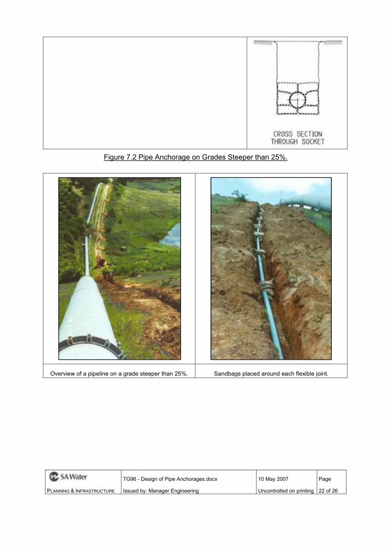
PLANNING & INFRASTRUCTURE
TG96 - Design of Pipe Anchorages.docx
Issued by
Figure 7.2 Pipe Anchorage on Grades Steeper than 25%.
Overview of a pipeline on a grade steeper than 25%.
Design of Pipe Anchorages.docx
Issued by: Manager Engineering
10 May 2007
Uncontrolled on printing
Pipe Anchorage on Grades Steeper than 25%.
a grade steeper than 25%. Sandbags placed around each flexible joint.
10 May 2007
Uncontrolled on printing
Page
22 of 26
Pipe Anchorage on Grades Steeper than 25%.
Sandbags placed around each flexible joint.

PLANNING & INFRASTRUCTURE
TG96 - Design of Pipe Anchorages.docx
Issued by
Spray concrete embedment being applied.
Note it flowing under the pipe.
Figure 7.3 - Pipe Anchorage on Grades Steeper than 25%.
Design of Pipe Anchorages.docx
Issued by: Manager Engineering
10 May 2007
Uncontrolled on printing
Spray concrete embedment being applied.
Note it flowing under the pipe. A view of the finished spray concrete embedment.
Pipe Anchorage on Grades Steeper than 25%.
10 May 2007
Uncontrolled on printing
Page
23 of 26
A view of the finished spray concrete embedment.
Pipe Anchorage on Grades Steeper than 25%.

PLANNING & INFRASTRUCTURE
TG96 - Design of Pipe Anchorages.docx
Issued by
Design of Pipe Anchorages.docx
Issued by: Manager Engineering
10 May 2007
Uncontrolled on printing
Appendix A: Drawings
10 May 2007
Uncontrolled on printing
Page
24 of 26

PLANNING & INFRASTRUCTURE
TG96 - Design of Pipe Anchorages.docx
Issued by
Design of Pipe Anchorages.docx
Issued by: Manager Engineering
10 May 2007
Uncontrolled on printing
10 May 2007
Uncontrolled on printing
Page
25 of 26

PLANNING & INFRASTRUCTURE
TG96 - Design of Pipe Anchorages.docx
Issued by
Design of Pipe Anchorages.docx
Issued by: Manager Engineering
10 May 2007
Uncontrolled on printing
10 May 2007
Uncontrolled on printing
Page
26 of 26