tfaws passive thermal paper session high temperature … · predicted heat pipe performance 0.5”...
TRANSCRIPT
Presented By
(Mohammed T. Ababneh, Ph.D.)
High Temperature Water-Titanium
Heat Pipe Radiators for the
Kilopower Fission Power System
William G. Anderson
Mohammed T. Ababneh
Derek Beard
Calin Tarau
Advanced Cooling Technologies, Inc.
Thermal & Fluids Analysis Workshop
TFAWS 2016
August 1-5, 2016
NASA Ames Research Center
Mountain View, CA
TFAWS Passive Thermal Paper Session

Outline
• Motivation
• Objectives
• Evaporator Design, Fabrication, and Testing
• Radiator Trade Study
• S-Bonded Radiator Fabrication and Testing
• Key Results & Future Work
• Acknowledgements
TFAWS 2016 – August 1-5, 2016 2

Motivation
• NASA Glenn is examining small fission
reactors for future space transportation
and surface power applications
– These Kilopower reactors would have an
8 to 15 year design life that could be
available for a 2020 launch to support
future NASA science missions
– Both 1 kWe thermoelectric and 3 kWe
Stirling systems have been examined
• Titanium-Water heat pipes have been
proposed to transport the waste heat
from the Stirling converters to the
system radiator
Mason, Gibson, and Poston, 2013
TFAWS 2016 – August 1-5, 2016 3

Objectives – (Phase II SBIR)
Overall objective: develop full-length titanium
water heat pipes for testing with the Stirling
convertors on the Kilopower demonstration unit
– Four Heat pipes/Two Stirling convertors
Sub-objectives:
– Design the heat pipe evaporator to interface
with the cold end of the Stirling convertor
– Design the radiator
– Extensive freeze/thaw testing
– Fabricate 4 heat pipes with radiator fins
– Testing of heat pipes at ACT, followed by
NASA Glenn
– Design of prototypic ISS experiment
– Additional heat pipe for shock and
vibration tests
TFAWS 2016 – August 1-5, 2016 4

Heat Pipe Wick
Wick must accommodate four operating conditions:
Space: Zero gravity; capillary forces must drive liquid return to evaporator
Earth, Slightly adverse: 0.1” – 0.3” evaporator superior to condenser
Earth, Gravity Aided: Fluid returned to evap. by gravity (thermosiphon)
Launch: Evaporator is superior to condenser; wick deprimes
Suitable Wick Structures
Kaya et. al, 2011
Hybrid (Screen-Groove)
Self-Venting Arterial
TFAWS 2016 – August 1-5, 2016 5

Predicted Heat Pipe Performance
0.5” outer diameter hybrid (screen-groove) heat pipe was selected
TFAWS 2016 – August 1-5, 2016 6

View of Stirling engines and
thermal management system
(Stirling cold end heat pipe
evaporators colored dark grey)
The cold end of the Stirling engine is
connected to the radiator panels via
titanium water heat pipes
In order to prevent damage from freezing of the
working fluid in the heat pipe grooves, an
accumulator will be used to contain the fluid
The heat pipes will mount to CSAF instead of
directly to the Stirling
Additionally, the heat pipes will be tested with a
annular heater block (inner diameter surface of
evaporator)
Evaporator Design
TFAWS 2016 – August 1-5, 2016 7

Dynamics of working fluid
𝑟𝑐𝑓𝑖𝑛𝑒_𝑠𝑐𝑟𝑒𝑒𝑛< 𝑟𝑐𝑐𝑜𝑎𝑟𝑠𝑒_𝑠𝑐𝑟𝑒𝑒𝑛
< 𝑟𝑐𝑔𝑟𝑜𝑜𝑣𝑒𝑠
At the interface of the grooved heat pipe
and evaporator, only the fine screen is in
contact with the grooves.
This ensures that coarse screen
(accumulator) fills with fluid only when the
fine screen is saturated and there is no heat
applied to the evaporator.
Therefore the accumulator only fills with
fluid when the heat pipe is not in operation
Bi-porous Wick Design (Evaporator)
Grooved heat pipe
Stirling
engine
Accumulator
(Coarse screen)
Liquid return
Vapor flow
Fluid return through: 1. Blue section (adiabatic)
2. Yellow section (bridges)
3. Red section (evaporator)
(Note: all are of fine screen)
Common fluid return for
all configurations
TFAWS 2016 – August 1-5, 2016 8

Groove-
Evaporator
Union (weld)
Evaporator Fabrication (CSAF)
• The evaporator is a weldment where each piece is screened individually
Vapor Space
Lined with 150
size mesh
Accumulator
To be filled with
100 size mesh
Heat Input
Surface
Accumulator
Grooves
Evaporator
TFAWS 2016 – August 1-5, 2016 9

Evaporator Testing
• Thermocouple map
• Test details
– Grooved heat pipe (from Phase I) length: 34” (reservoir , condenser,
adiabatic)
– Condenser length: 5”
– NCG Reservoir length: 3”
– Heater block only applies heat to the evaporator (not the accumulator)
– Accumulator is inferior to the evaporator for all test cases
Evaporator
TCs 1,2,8
Accumulator
TCs 5,6
Adiabatic
TCs 11-19 odd (bottom)
TCs 12-20 even (top)
Condenser
TCs 21-23 Reservoir
TCs 25-27 11, 12
13, 14
15, 16
17, 18
19, 20
TFAWS 2016 – August 1-5, 2016 10
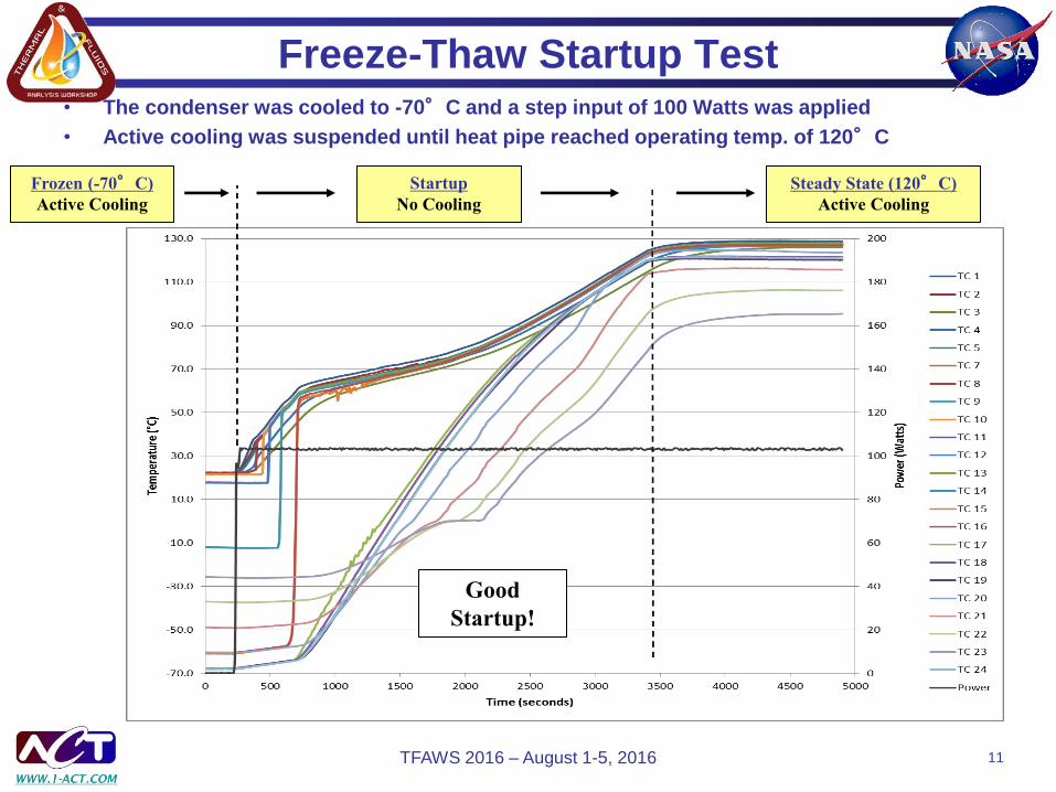
Freeze-Thaw Startup Test
• The condenser was cooled to -70°C and a step input of 100 Watts was applied
• Active cooling was suspended until heat pipe reached operating temp. of 120°C
Frozen (-70°C)
Active Cooling
Startup
No Cooling
Steady State (120°C)
Active Cooling
Good
Startup!
TFAWS 2016 – August 1-5, 2016 11

Freeze-Thaw Startup Test
• Snapshot of temperature distribution at frozen and steady state
Evaporator
Accumulator
Adiabatic
Condenser
Reservoir Frozen
Steady State
Series:
0°C
TFAWS 2016 – August 1-5, 2016 12

Performance Testing
• Initial performance tests showed ~130 Watt transport
– Does not meet requirement (250 Watt)
– Monel screen was used in place of Titanium because of cost, but was not oxidized for proper wetting; therefore we suspect wetting angle is large, so capillary pumping is small
– Performed a non-invasive oxidation procedure to treat the Monel screen
• Performance test after oxidation showed 190 Watt transport
– Improvement, but still does not meet requirement (oxidation not sufficient)
Dry out
TFAWS 2016 – August 1-5, 2016 13
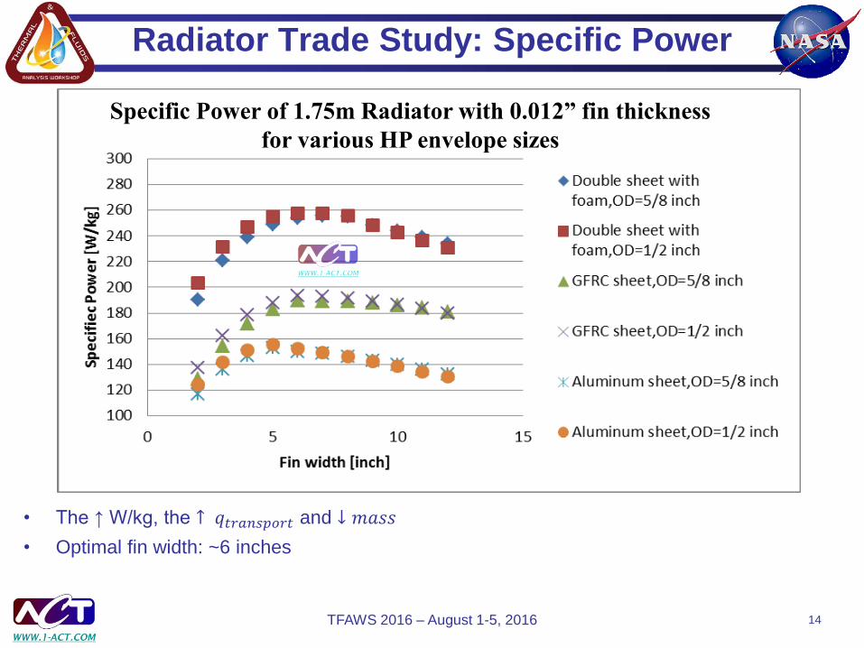
Radiator Trade Study: Specific Power
• The ↑ W/kg, the ↑ 𝑞𝑡𝑟𝑎𝑛𝑠𝑝𝑜𝑟𝑡 and ↓ 𝑚𝑎𝑠𝑠
• Optimal fin width: ~6 inches
Specific Power of 1.75m Radiator with 0.012” fin thickness
for various HP envelope sizes
TFAWS 2016 – August 1-5, 2016 14

Aluminum Radiator
• Aluminum radiator is cheaper and more readily available than GFRC or
double sheet with honeycomb panels and POCOFoam saddles
• S-Bond is a high temperature solder for Aluminum to Titanium
• Prototype thermosyphon radiator
Top view
Bottom view
TFAWS 2016 – August 1-5, 2016 15

Testing in the Vacuum Chamber
Painted radiator with
Aeroglaze A276 to
increase the
emissivity.
Evaporator
TFAWS 2016 – August 1-5, 2016 16

S-Bonded Radiator Performance Test: Vacuum
TFAWS 2016 – August 1-5, 2016 17

Results in Vacuum
Bottom view Top view
TFAWS 2016 – August 1-5, 2016 18
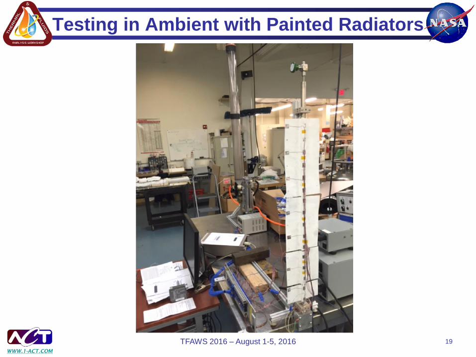
Testing in Ambient with Painted Radiators
TFAWS 2016 – August 1-5, 2016 19

Results – Thermal Imaging in Ambient
TFAWS 2016 – August 1-5, 2016 20

∆Temperature heat pipe and root of aluminum fin
0.000
0.200
0.400
0.600
0.800
1.000
1.200
1.400
1.600
0 1 2 3 4
De
lta
T [C
]
Panel number
1 2 3 4
TFAWS 2016 – August 1-5, 2016 21

Radiator Thermal Cycle Testing
• Tested S-Bond for viability titanium - aluminum joint
– Preliminary testing shows positive results
• Low temperature gradient (0.3 C) across joint
• 19 cycles in vacuum environment from 40 C to 140 C without degradation
Thermal Cycling of S-Bonded Radiator Under Vacuum
TFAWS 2016 – August 1-5, 2016 22

Key Results & Future Work
• Key Results
– Developed a working hybrid heat pipe with similar geometry to final
configuration
– Demonstrated freeze-thaw capability of hybrid heat pipe
– Developed Aluminum radiator using S-Bond
– Validated radiator performance by testing in vacuum and ambient
• Future Work
– Revise evaporator design for better performance
– Integrate heat pipe and radiator thermal models to determine final
configuration
– Fabricate and test 4 heat pipe radiator deliverables
TFAWS 2016 – August 1-5, 2016 23
Acknowledgements
This program was sponsored by NASA Glenn Research Center
under Contract Numbers NNX14CC27P and NNX15CC06C.
Maxwell Briggs was the Technical Monitor
We would like to thank Maxwell Briggs and Marc Gibson for their
helpful suggestions
TFAWS 2016 – August 1-5, 2016 24

Questions ?
INNOVATIONS IN ACTION
The Thermal Management Experts
TFAWS 2016 – August 1-5, 2016 25