tf 705-r-21 innovative slabs-on-ground
TRANSCRIPT

1
TECH FACT
Innovative Ways to Reinforce Slabs-On-Ground Formulas for Success BACKGROUND With nearly a century of experience in designing slabs-on-ground, both with and without welded wire reinforcement (WWR), there is little question that the reinforced slabs provide superior performance over those that are not reinforced. Rather, the question is, “What constitutes adequate reinforcement?”
Since inadequately reinforced slabs-on-ground will perform little better than those that are not reinforced, properly specified and placed WWR is key to the success of the final product. The following explanations and formulas are supplied to the design professional to clarify the function of reinforcing steel and to provide a guide for selecting the proper procedure.
PURPOSE OF REINFORCEMENT In elevated concrete structures, the purpose of reinforcement is well understood as being necessary to control positive and negative moment and to control shear. Since concrete has little tensile strength, all tensile components are expected to be serviced by the tensile capacity of the reinforcing in these elevated structures.
In slab-on-ground design, slab thickness is a function of the modulus of rupture of the concrete. This brings us to the evident conclusion that the concrete is not supposed to crack. Since the normal role of steel reinforcement hinges on the fact that the concrete must crack for the steel to perform, the designer is faced with a paradox. It is therefore necessary to define both the purpose of reinforcing slabs-on-ground and how this is effectively accomplished. There are three primary purposes for reinforcing slabs-on-ground and they are as follows:
1. Shrinkage Control 2. Temperature Control 3. Moment Capacity
Some may consider increased joint spacing as a purpose, but this is simply an extension of shrinkage control. The suggested range of maximum joint spacings for concrete floors on ground is determined relative to slab thickness. The author believes reinforcement designed by subgrade drag theory should be limited to slabs with joints in this range.
TF 705-R-21
Excellence Set in Concrete® For more information on WWR visit our website.
WireReinforcementInstitute.org
• Tech Facts • Case Studies • Producer Plants • Online Learning • Videos
2
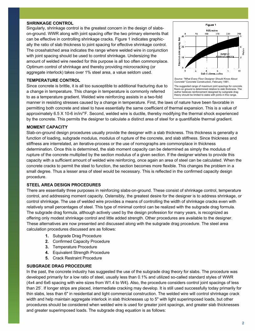
SHRINKAGE CONTROL Singularly, shrinkage control is the greatest concern in the design of slabs-on-ground. WWR along with joint spacing offer the two primary elements that can be effective in controlling shrinkage cracks. Figure 1 indicates graphic-ally the ratio of slab thickness to joint spacing for effective shrinkage control. The crosshatched area indicates the range where welded wire in conjunction with joint spacing should be used to control shrinkage. Undersizing the amount of welded wire needed for this purpose is all too often commonplace. Optimum control of shrinkage and thereby providing microcracking (or aggregate interlock) takes over 1% steel area, a value seldom used.
TEMPERATURE CONTROL Since concrete is brittle, it is all too susceptible to additional fracturing due to a change in temperature. This change in temperature is commonly referred to as a temperature gradient. Welded wire reinforcing assists in a two-fold manner in resisting stresses caused by a change in temperature. First, the laws of nature have been favorable in permitting both concrete and steel to have essentially the same coefficient of thermal expansion. This is a value of approximately 6.5 X 10⁻⁶ in/in/°F. Second, welded wire is ductile, thereby modifying the thermal shock experienced by the concrete. This permits the designer to calculate a distinct area of steel for a quantifiable thermal gradient.
MOMENT CAPACITY Slab-on-ground design procedures usually provide the designer with a slab thickness. This thickness is generally a function of loading, subgrade modulus, modulus of rupture of the concrete, and slab stiffness. Since thickness and stiffness are interrelated, an iterative-process or the use of nomographs are commonplace in thickness determination. Once this is determined, the slab moment capacity can be determined as simply the modulus of rupture of the concrete multiplied by the section modulus of a given section. If the designer wishes to provide this capacity with a sufficient amount of welded wire reinforcing, once again an area of steel can be calculated. When the concrete cracks to permit the steel to function, the section becomes more flexible. This changes the problem in a small degree. Thus a lesser area of steel would be necessary. This is reflected in the confirmed capacity design procedure.
STEEL AREA DESIGN PROCEDURES There are essentially three purposes in reinforcing slabs-on-ground. These consist of shrinkage control, temperature control, and addressing moment capacity. Ostensibly, the greatest desire for the designer is to address shrinkage, or control shrinkage. The use of welded wire provides a means of controlling the width of shrinkage cracks even with relatively small percentages of steel. This type of minimal control can be realized with the subgrade drag formula. The subgrade drag formula, although actively used by the design profession for many years, is recognized as offering only modest shrinkage control and little added strength. Other procedures are available to the designer. These alternatives are now presented and discussed along with the subgrade drag procedure. The steel area calculation procedures discussed are as follows:
1. Subgrade Drag Procedure 2. Confirmed Capacity Procedure 3. Temperature Procedure 4. Equivalent Strength Procedure 5. Crack Restraint Procedure
SUBGRADE DRAG PROCEDURE In the past, the concrete industry has suggested the use of the subgrade drag theory for slabs. The procedure was developed primarily for a low ratio of steel, usually less than 0.1% and utilized so-called standard styles of WWR (4x4 and 6x6 spacing with wire sizes from W1.4 to W4). Also, the procedure considers control joint spacings of less than 25’. If longer strips are placed, intermediate cracking may develop. It is still used successfully today primarily for thin slabs, less than 6" in residential and light commercial construction. The welded wire will control shrinkage crack width and help maintain aggregate interlock in slab thicknesses up to 5" with light superimposed loads, but other procedures should be considered when welded wire is used for greater joint spacings, and greater slab thicknesses and greater superimposed loads. The subgrade drag equation is as follows:
Source: "What Every Floor Designer Should Know About Concrete" Concrete Construction, February 1981.
The suggested range of maximum joint spacings for concrete floors on ground is determined relative to slab thickness. The author believes reinforcement designed by subgrade drag theory should be limited to slabs with joints in this range.

3
where As = cross-sectional area in square inches of steel per lineal foot of slab width
Fs = allowable stress in reinforcement, psi use 0.75fy
F = the friction factor, use a range of 1.5 - 2, use 2
L = distance in feet between joints (the distance between the free ends of the slab that can move due to shrinkage contraction or thermal expansion)
W = dead weight of the slab, psf, usually assumed to be 12.5 psf per inch of thickness
The value of two in the denominator is not a safety factor. It is based on the theory that the slab panel will move an equal distance from each end toward the center. This may not always be the situation (thus the expanded definition of L). F, the friction factor, can vary from 0.5 upwards. A value of 2 should be used when further information is not available.
Values of the coefficient of friction can vary substantially as seen in Figure 2. In selecting a value, it is always advisable to be conservative since subgrades can often be uneven resulting in a greater subgrade friction.
CONFIRMED CAPACITY PROCEDURE As previously stated, most floor slabs-on-ground have their thickness selected based on a given design procedure (use Figure 3 for wheel load criteria). This procedure may be the PCA design method, the WRI design procedure, the Corps of Engineers procedure or the designer’s computer analysis. These procedures result in a thickness selection capable of resisting a determined positive and negative moment based on design input such as subgrade modulus, magnitude and location of loads and other factors. The bottom line is that the slab must be capable of resisting a certain internal moment, possibly either positive or negative. In the vicinity of a shrinkage crack, this capacity has been compromised in the past, if reinforcing such as welded wire reinforcing is not present.
The needed moment capacity of the slab is simply the modulus of rupture multiplied by the section modulus. The minimum reinforcing is therefore likely to be the steel area that has an ultimate capacity equal to the design moment. This moment value would be the section modulus multiplied by the working stress.
Working stress is defined as the MOR divided by the safety factor. If we were to assume that a single layer of welded wire reinforcing were located in the middle of the slab, the problem is simplified because the capacity is equal for both positive and negative moment capacity. If we were to assume the 6” thickness used in the previous procedure and the working stress of the modulus of rupture were 4 f’c the problem is further simplified. With these assumptions, the confirmed capacity procedure simplifies to the following formula:
where As = cross-sectional area in square inches of steel per lineal foot of slab width
t = thickness of the slab in inches
f’c = compressive strength of the concrete (psi)
fy = yield stress of the reinforcement (psi)
Source: "Design and Constrcution of Post-Tensioned Slabs on Ground" Post-Tensioning Institute, 1991.
Variation in values of coefficient for five-inch slabs on different bases and subbases.

4
A designer should consider the confirmed capacity procedure as a reasonable minimum cross-sectional area for reinforcement of slabs-on-ground, as it will secure a minimum moment capacity regardless of shrinkage joint or crack location. Another version:
Note: SF is normally taken as 2. The first reference noted on page 7 will provide the designer more background on safety factors.
TEMPERATURE PROCEDURE A procedure available for the control of crack size in slabs-on-ground can be found in the temperature control method. Concrete slabs-on-ground will, more than likely, crack. Limiting the size of cracks can be effected by placing sufficient welded wire reinforcing in the slab to address the maximum change in temperature the slab is likely to experience. Climate controlled industrial slabs-on-ground should normally be designed for a minimum temperature differential or temperature gradient of 40°F. Slabs designed for extreme exposure should be designed for the maximum extremes the climate dictates. This could produce a thermal gradient of 100°F or greater. This procedure does not reduce cracking; however, it should assist significantly in controlling crack widths to maintain aggregate interlock. The temperature method for checking the required reinforcement is stated as:
where
As = the cross-sectional area in square inches of steel per lineal foot of slab width
t = thickness of slab in inches
fr = tensile strength of concrete (psi) (calculated at 0.4 x MOR)
fs = working stress in reinforcement (psi)
T = range of temperature the slab is expected to be subjected to (°F)
∝= thermal coefficient of concrete (in/in°F)
Es = modulus of elasticity of steel (psi)
The normal range of the coefficient of thermal expansion (∝) of concrete is 5 -7 x 10 -6 in/in°F.
The intent is to minimize shrinkage crack frequency and width based on anticipated temperature changes. The use of a thermal gradient of less than 40°F is not recommended even in environmentally controlled conditions.
EQUIVALENT STRENGTH PROCEDURE The equivalent strength procedure is referred to as the concrete to steel ratio. The steel area is calculated based on 75% of the yield strength of the steel. The tensile strength of the concrete is taken as 0.4 times the modulus of rupture (MOR). The modulus of rupture can be safely taken as . This results in the following formula:
As = cross-sectional areas in square inches of steel per lineal foot of slab width
t = thickness of the slab in inches
f’c = compressive strength of the concrete (psi)
fs = working stress in reinforcement (psi)
This method produces a significantly higher steel percentage than normally encountered.
5
Use of this procedure will significantly reduce the frequency of cracks in the 40-mill width range. It will not eliminate them completely, however. Applications for this design procedure are highway paving, airport taxiways and runways and industrial building slabs and truck ramps, parking and roadways. See the list of references for other sources of recommendations.
CRACK RESTRAINT PROCEDURE A procedure for providing maximum control of shrinkage cracks is available. The likelihood of its implementation based on the steel requirements becomes restrictive.
Although microcracking cannot be absolutely guaranteed, the favorability of microcracking is dependent on the shrinkage potential of the concrete. For most industrial floors this can be taken as:
where
As = cross-sectional area in square inches of steel per lineal foot of slab width
t = thickness of the slab in inches
fy = yield strength of steel reinforcing
This formula is the result of equating unit concrete shrinkage to a steel cross sectional area capable of resisting this potential change in length. This procedure would be applied primarily to food processing operations, hospitals and other applications requiring more restraint of microcracking, which works out to 1% of the slab cross sectional area. A simple derivation of the crack restraint formula can be found in Appendix 2.
It is recommended that the designer at least check the subgrade drag equation and the confirmed capacity equation in selecting welded wire reinforcing for slabs-on-ground. The greater value of the two procedures is suggested to be a minimum cross-sectional area requirement.
It is important for the designer to keep in mind that unless joint spacings are extremely close, concrete will crack. It is therefore necessary to provide the owner with the security that the slab will function with minimal maintenance when cracks and crack widths are kept to a minimum. Confirmed capacity design offers this security to the owner, contractor, and the design professional.
APPENDIX 1
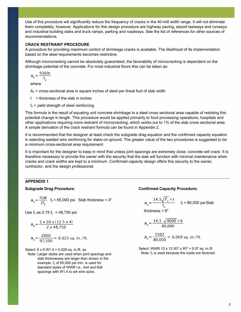
Subgrade Drag Procedure:
fy = 65,000 psi Slab thickness = 4"
Use fs as 0.75 fy = 48,750 psi
Select: 6 x 6 W1.4 = 0.028 sq. in./ft. as Note: Larger styles are used when joint spacings and
slab thicknesses are larger than shown in the example. fy of 65,000 psi min. is used for standard styles of WWR i.e., 4x4 and 6x6 spacings with W1.4 to w4 wire sizes.
Confirmed Capacity Procedure:
fy = 80,000 psi Slab
thickness = 6"
Select: WWR 12 x 12 W7 x W7 = 0.07 sq. in./ft. Note: fy is used because the loads are factored.
6
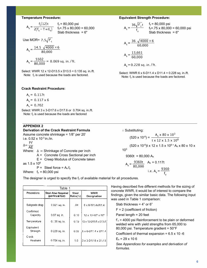
Temperature Procedure:
fy = 80,000 psi fs=.75 x 80,000 = 60,000 Slab thickness = 6"
Use MOR=
Select: WWR 12 x 12-D13.5 x D13.5 = 0.135 sq. in./ft. Note: fy is used because the loads are factored.
Equivalent Strength Procedure:
fy = 80,000 psi fs=.75 x 80,000 = 60,000 psi Slab thickness = 6"
Select: WWR 6 x 6-D11.4 x D11.4 = 0.228 sq. in./ft. Note: fy is used because the loads are factored.
Crack Restraint Procedure:
Select: WWR 3 x 3-D17.6 x D17.6 or 0.704 sq. in./ft. Note: fy is used because the loads are factored
APPENDIX 2 Derivation of the Crack Restraint Formula Assume concrete shrinkage = 1/8” per 20’ i.e. 0.52 x 10⁻³ in./in.
∆=PℓAE
Where: ∆= Shrinkage of Concrete per inch A = Concrete Cross Sectional per inch E = Creep Modulus of Concrete taken as 1.5 x 10⁶
P = Steel force = As fy
Where: fy = 80,000 psi
∴ Substituting:
(520 x 10-6) =
(520 x 10-6)t x 12 x 1.5 x 106 = As x 80 x 10 x 103
9360t = 80,000 As
As = 0.117t
The designer is urged to specify the fy of available material for all procedures.
Having described five different methods for the sizing of concrete WWR, it would be of interest to compare the findings, given the similar basic data. The following input was used in Table 1 comparison:
Slab thickness = 4” or 6” F = 2 (coefficient of friction) Panel length = 20 feet f’c = 4000 psi Reinforcement to be plain or deformed welded wire with yield strengths from 65,000 to 80,000 psi. Temperature gradient = 50°F Coefficient of thermal expansion = 6.5 x 10 -6 Es = 29 x 10 6 See Appendices for examples and derivation of formulas.

7
REFERENCES
Designing Floor Slabs on Grade, Boyd Ringo and Robert Anderson, 1992, 1996.
WRI Structural WWR Detailing Binder, 10 Chapters, section 2 has tables comparing areas and weights of rebar and WWR with various yield strengths of wire.
Video, “A Visit to a Distribution Center Construction Site, A Contractor’s Views,” 1995.
WRI Manual of Standard Practice, WWR 500, 1992, includes metric wire sizes and WWR styles, 1995.
Tests to Determine Performance of Deformed Welded Wire Fabric Stirrups, AC/ Structural Journal, 91-S22, Griezic, Cook & Mitchell.
Evaluation of Joint-Shear Provisions for Interior BeamColumn-Slab Connections Using High-Strength Materials, AC/ Structural Journal, 89-S10, Guimaraes, Kreger, Jirsa.
Ductility of Wire Reinforcing - Industry Evaluation of WWR Elongation and Reduction of Area, 1992. Means Concrete & Masonry Cost Data, 1996.
Some Observations on the Physical Properties of Wire for Plain and Deformed Welded Wire, A.B. Dove, AC/ Journal Technical Paper, 1983.
ASTM Volume 01.04 - Steel Reinforcing, A370, A4. Round Wire Products, A4.4.2.
AC/, Design and Construction of Concrete Slabs on Grade, SCM-11 (86) with PCA’s Concrete Floors on Ground, Third Edition inserted, p.10 Design Procedure, Vehicle Loads, and p.12 High-RackStorage-Leg Loads.
PCA, Design of Concrete Airport Pavement, Chapter 5, Steel in Jointed Pavements, Distributed Steel, Robert G.Packard.
CRSI, Placing Reinforcing Steel, 6th Edition, Chapter 15, Highway and Airport Pavement, Continuously Reinforced Concrete Pavement and Jointed Reinforced Concrete Pavement.
Disclaimer
This publication and its contents, including, but not limited to, textual material, graphs, tables, charts, calculations, statistics, photographs and/or drawings are made available by the WRI “AS IS” and as an informational resource only. WRI, its officers, directors, employees, agents, contractors, volunteers, members, and consultants DISCLAIM ANY AND ALL EXPRESS AND IMPLIED WARRANTIES, CONDITIONS, REPRESENTATIONS, OR OTHER TERMS (INCLUDING AS TO SATISFACTORY QUALITY, FITNESS FOR A PARTICULAR PURPOSE, SUITABILITY OR MERCHANTABILITY) with respect to the publication and its contents. To the fullest extent permitted by applicable law, WRI fully disclaims any and all liability or responsibility for any damages, injuries or losses to persons, property, or business, including, but not limited to, lost profits, direct, indirect, incidental, consequential or punitive damages, costs, and expenses, including attorneys’ fees and court costs, arising out of, or related to the downloading and/or use of this publication and its contents.
For more information visit our website: WireReinforcementInstitute.org

8