texture and shape synthesis on surfaces
TRANSCRIPT

Texture and Shape Synthesis on SurfacesLexing Ying, Aaron Hertzmann, Henning Biermann, Denis Zorin
New York Universityhttp://www.mrl.nyu.edu
Abstract. We present a novel method for texture synthesis on surfaces fromexamples. We consider a very general type of textures, including color, trans-parency and displacements. Our method synthesizes the texture directly on thesurface, rather than synthesizing a texture image and then mapping it to the sur-face. The synthesized textures have the same qualitative visual appearance asthe example texture, and cover the surfaces without the distortion or seams ofconventional texture-mapping. We describe two synthesis methods, based on thework of Wei and Levoy and Ashikhmin; our techniques produce similar results,but directly on surfaces.
1 Introduction
Computer graphics applications increasingly require surfaces with highly detailed re-flective properties, geometry and transparency. Constructing such detailed appearancesmanually is a difficult and tedious task. A number of techniques have been proposed toaddress this problem; procedural synthesis techniques are among the most widely used.A number of recent techniques [4, 13, 2] make it possible to synthesize textures fromexamples.
Creating a surface with a complex appearance can be viewed as synthesis of a col-lection of functions on an arbitrary two-dimensional domain. These functions includecolor, transparency, normals and coordinates of surface points. We will refer to all suchfunctions as textures. The textures can be thought of as continuous and defined di-rectly on surfaces, although they will be represented as samples in implementation. Inthis view, previously proposed example-based texture synthesis algorithms synthesizeattributes for a special kind of surfaces, i.e. flat rectangles.
In this paper, we extend synthesis from examples to arbitrary surfaces. The obviousapproach to the problem, synthesizing a texture on a rectangle and mapping it to anarbitrary surface, is likely to result in artifacts (e.g. seams or shape distortion); typi-cally, creating high-quality maps requires considerable user intervention. Performingsynthesis directly on a surface avoids many of the these problems.
Existing texture synthesis methods rely on the presence of identical, regular sam-pling patterns for both the example and the synthesized texture. Therefore, it is impos-sible to apply such methods directly to surfaces. In this paper, we regard the exampleand the synthesized texture as continuous functions that happen to be represented bysamples, but not necessarily laid out in identical patterns. Whenever necessary, weresample either the example or the synthesized texture on a different pattern.
We describe two specific synthesis methods, based on the methods of Wei andLevoy [13] and Ashikhmin [2]. As with image synthesis, the choice of algorithm de-pends primarily on the texture.
The main contributions of this paper are: generalizations of existing image texturesynthesis methods to synthesis on surfaces; synthesis of surface texture maps indepen-

dent of parameterization; efficient and accurate neighborhood sampling operations; andsynthesis of texture, transparency, and displacements.
2 Related Work
Recently, several nearest-neighbor methods have been shown to produce textures ofgood quality. De Bonet [3] demonstrates a coarse-to-fine procedure that fills in pix-els in an output texture image pyramid by copying pixels from the example texturewith similar coarse image structure. Efros and Leung [4] create texture using a single-scale neighborhood. Wei and Levoy [13] combine the methods of [3, 4] by using aneighborhood that contains both coarse-scale and same-scale pixel information, and useTree-structured vector quantization (TSVQ) [5] to accelerate the search for the nearestneighbor. Ashikhmin [2] produces high-quality textures by copying contiguous texturepatches when possible.
Neyret and Cani [10] texture a surface isotropically by tiling from a small collec-tion of tileable example texture triangles. Praun et al. [11] extend this by placing ori-ented texture patches over an independent parameterization of a surface. Althoughthese methods produce high-quality results for many textures, they have some draw-backs: they cannot use texture patches that are large with respect to the surface shape,they cannot capture low-frequency texture without sacrificing high-frequency random-ness, and the texture patches do not necessarily line up exactly, which requires carefulselection of the patch shapes, and blending to hide discontinuities between patches.
In work concurrent to our own, Wei and Levoy [14] and Turk [12] develop methodsfor texture synthesis on surfaces. These methods also generalize Wei and Levoy’s mul-tiscale image texture synthesis algorithm [13]. We believe that our approach has severaladvantages. First, we define a fast method for neighborhood sampling that guaranteesthat there will not be any folds in the sampling grid, in contrast to relaxation [14] andsurface marching [12]. Second, we synthesize directly to surface texture maps ratherthan to a densely tesselated mesh, meaning that our algorithm will be faster and requiremuch less memory. However, we do require that the surface be covered with texturemaps, and that charts can be constructed. Finally, we also generalize Ashikhmin’s al-gorithm, which gives good results for many textures that are handled poorly by themultiscale synthesis algorithms.
3 Overview
Given a 2D example and a 3D surface, our goal is to create a texture that “looks like” itcame from the same process that generated the example. We make the assumption thatthis is equivalent to requiring the texture on every small surface neighborhood to “looklike” the texture on some neighborhood in the example.1 The example and synthesizedtextures will be discretized into samples, although not necessarily with the same sampledensity. The texture may be from any domain: in particular, we explore image textures,transparency textures and geometric textures. For brevity, we refer to the synthesizedtexture as target.
1This formulation is based on the Markov condition assumption on the texture: we assume that the texturehas local statistics (the value at a point depends only on its local neighborhood), and stationary statistics (thedependence is the same for every point). These assumptions imply that the the surface texture will “look like”the example texture if this joint density of texture values is the same for the surface as for the example.

Review of image texture synthesis: We now briefly review image texture synthesis al-gorithms; see the relevant papers for details. Efros and Leung [4] synthesize a texture inscan-line order. For each pixel, the already-synthesized values in neighborhood of thetarget pixel x are collected, and the example texture is searched to find pixel y with theneighborhood that matches the target neighborhood as closely as possible. The value ofthe pixel y is copied to the pixel x. Wei and Levoy [14] synthesize a Gaussian pyramidfrom coarse to fine. Each level of the pyramid is synthesized as in the Efros-Leungalgorithm, except that samples are collected from the neighborhood at both the currentscale and the coarser scale, and that TSVQ is used to accellerate the nearest-neighborssearch.
Ashikhmin [2] synthesizes a texture in the same manner as Efros-Leung, exceptthat only a restricted range of candidates for each pixel is tested. When synthesizinga value for a pixel x, we first consider each already-synthesized pixel yi adjacent to x.Some source pixel y′
i in the example texture was previously copied to yi. If we wereto continue copying from the same patch of the example texture used for y′i, then xwould get the value at location y′
i + (x − yi); this location is used as a candidate for x.Each yi generates a candidate. We compare the neighborhood of each candidate to theneighborhood of x, and copy the color from the closest match yi to x.
Texture representation: For simplicity, we assume that the example texture is resam-pled on a rectangular sampling grid, i.e. that it is an image. The target texture is rep-resented by samples on the surface (i.e. by texture maps). We assume that there is acollection of rectangular images mapped to the surface and the texture samples will bestored in these images.
An important feature of our approach is that the synthesis process is independentof the choice of the texture-mapping parameterization: given a parameterization, ourmethod will synthesize a texture without distortion on the surface. However, parametriza-tion distortion may result in blurry textures in some areas.
Idea of our algorithms: For each sample of the target texture, we consider the previously-synthesized texture within a small neighborhood of the sample. Then we locate a sim-ilar neighborhood in the example and copy the value of the texture in the center of theneighborhood to the target sample.
Several issues need to be addressed to make this idea practical:
• how to pick a neighborhood of samples from the target texture,• how to compare neighborhoods in the target and example,• how to find similar neighborhoods in the example.
The two methods that we describe use somewhat different approaches to these prob-lems. Each method has its strengths and weaknesses, illustrated in Section 6. Bothmethods use a common sampling pattern for the example and target textures to makethe comparison possible, but use different approaches to resampling as discussed below.
Surface orientation: As most interesting textures are anisotropic, orientation must beestablished on the surface. We use a vector field to specify the correspondence betweenorientation on the surface and orientation in the domain of the example texture. A pairof orthogonal tangent vector fields v1 and v2 is used for this purpose. To compare thetexture on the surface neighborhood centered at x to a neighborhood centered at y in

the example texture we establish a map between the neighborhoods, mapping x to yand v1 and v2 to the coordinate directions in the example.
The field v1 is computed using the method described in [7]2. The field v2 is com-puted as the cross-product of v1 and the oriented surface normal. The field could alsobe specified interactively, as in [11, 12].
Synthesis methods: Our first method is based on [13] and described in Section 4. Foreach generated sample x, we attempt to find the neighborhood in the entire exampletexture that matches the neighborhood of x as closely as possible. The sampling patternof the example is used to resample the neighborhood of the target. As the example is aregularly sampled image, the fixed sampling pattern makes it possible to accelerate thesearch with standard nearest-neighbors algorithms, such as TSVQ.
The second method, based on [2] (Section 5), selects candidate values only fromexample neighborhoods that are spatially close in the example with some already-synthesized sample near x (coherent synthesis). This makes it necessary to keep trackof the source of each generated sample. In this method, we use the target samplingpattern for comparison of neighborhoods, which is simpler than resampling the target.Acceleration (such as with TSVQ) is unnecessary in this method, because only a fewneighborhoods will be tested.
4 Multiscale Synthesis
Our first method is based on the multiscale image synthesis procedure of Wei and Levoy[13]. In this method, we first synthesize a coarse version of the surface texture and thenperform coarse-to-fine refinement. This method allows us to efficiently capture bothcoarse and fine-scale statistics, while performing several iterative refinements to thetexture.
Our algorithm requires that the surface is covered by an atlas of sufficiently largeoverlapping charts. A chart is a map from a part of a surface into the plane; everypoint should be in the interior of a chart. Charts allow us to efficiently sample smallneighborhoods of points.
Chart construction is relatively easy for a large class of texture-mapped surfaces,including polygonal meshes. If a surface is tiled with quadrilateral or any other polyg-onal texture maps, we can construct vertex charts from the texture maps. The texturemaps themselves form a mesh on the surface. We can create a chart for each vertex ofthe mesh by flattening the collection of texture-mapped regions sharing the vertex tothe plane, as explained below. Clearly, the resulting charts cover the whole surface, andany point on the surface is in the interior of one of the charts.
Chart construction is particularly simple for multiresolution subdivision surfaces,which we use in our implementation. There are several methods available for convert-ing an arbitrary mesh to this representation [8, 6, 15], but we emphasize that this isnot essential for our algorithm; as long as a tiling of the surface with texture maps isavailable, any representation can be used.
Our algorithm begins by creating a Gaussian pyramid for the example image andfor each of the target texture maps. Every level of the hierarchy will be synthesized,from coarse-to-fine.
2Since we are optimizing a vector field, and do not desire 90o-invariance as in [7], the optimizationformula is of the form
∑cos((θi − ϕij) − (θj − ϕji)) instead of
∑cos 4((θi − ϕij) − (θj − ϕji)).

Our synthesis methods iterate over the surface texture maps in breadth-first order.Within each texture map, we synthesize in scan-line order, starting from a scan-line thatis adjacent to an already-synthesized texture.
We use a brute-force search to synthesize the coarsest level. In order to synthesizea sample x, we sample the previously synthesized target texture in a neighborhood of xusing the regular pattern of the example, and the surface marching technique describedin the next section. Then we exhaustively search the example to find the nearest matchunder a weighted l2-norm. We then copy the central sample from the best-matchingneighborhood to x. Samples are weighted with a Gaussian kernel in image space. Wesample texture values by bilinear interpolation of the four nearest neighboring valuesfrom the target texture maps. However, if some of these values have not yet beengenerated, then instead we use the nearest already-generated neighbor. If none of thevalues are available, then no sample value is generated at that location. This brute-forcesearch is inefficient, but the coarse-level synthesis is nonetheless fast because there arevery few samples to search over or to synthesize at the coarsest level of the pyramids.
We synthesize each of the remaining levels using a two-pass algorithm based on Weiand Levoy’s [13] hole-filling algorithm. In the first pass, we synthesize each sample ofa level of the hierarchy using a 5 × 5 neighborhood that contains only samples fromthe coarser level of the pyramid. In the second pass, we refine the texture at the currentlevel using the composition of the 9 × 9 neighborhood from the current level and a5 × 5 one from the coarser level. This means that all samples in each neighborhoodhave already been synthesized, allowing us to use TSVQ [5] or Approximate NearestNeighbors [1] to accelerate the nearest-neighbors searches in both passes. The bestmatch found during these searches is copied to the target sample. We also introducesome randomness into the search, with the same randomization used in [3, 13]: welocate the eight nearest matches found during the TSVQ traversal with backtracking,discard all matches that have a distance worse than the best match by a factor of 0.1,and then randomly pick one of the remaining matches by uniform random sampling.
We use two different methods for sampling neighborhoods on a surface. For thecoarsest levels of the image hierarchy, we use surface marching, in which we traverseover smoothed geometry to locate sample points. For the remainder of the image hierar-chy, we perform chart sampling, in which we construct sampling neighborhood patternsin a globally-defined parametric domain. In our experiments, chart sampling performstwice as fast; marching is only used for coarse levels where chart sampling cannot beused (for reasons described below).
4.1 Surface Marching
In the surface marching algorithm, we collect a grid of sample locations that corre-sponds to a grid of locations in the plane (Figure 1), using a tesselated mesh represen-tation of the surface. For each sample point, we compute the angle and distance in theplane to the point. We then draw a straight path from the center surface point in thecomputed distance and direction (with respect to the orientation field on the mesh) tofind the corresponding surface sample point. When the path intersects a mesh edge,the line is continued on the adjacent face, at the same angle to the mesh edge as on theprevious face.
Note that other choices of path shape could be used to march from the center pointto the target sample point. In particular, Turk [12] uses a path that corresponds tomarching up or down in the texture domain, then left or right to find the sample point.In general, however, each of these paths may reach different parts of the surface. We

(a) (b) (c)
Fig. 1. Surface marching for neighborhood sampling. (a) A 5 × 5 rectangular surface neigh-borhood pattern on an image. (b) Each sample location in the neighborhood may be reached bya straight line from the center pixel. (b) A corresponding sampling pattern on a surface. Fromthe center sample, we “march” over the surface, in directions corresponding to the straight-linedirections in the image plane. This gives us a set of surface sample locations. Values at eachlocation are determined by bilinear sampling from the texture map. The orientation of the patternis determined by the surface vector field.
believe that the diagonal path described above is preferable, because it is the shortestsuch path, and thus least prone to distortion due to irrelevant features.
Regardless of which path we use, there are several problems with the surface march-ing approach. First, it is not guaranteed to give even sampling of a surface neighborhoodin irregular geometry. Second, the sampling pattern is numerically unstable, as minutesurface variations can cause substantial variations in the pattern. Finally, this method isrelatively slow, because of the many geometric intersection and projection operationsrequired.
4.2 Chart Sampling
Rather than trying to move on the surface from one face to the next, one can takeadvantage of a suitable surface parameterization. Recall that our goal is to be able tosample the texture at (approximately) regularly spaced locations around a sample x.Suppose a sufficiently large part of the surface around x is parameterized over a planardomain V . Then we can sample in the parametric domain V , choosing the samplingpattern in such a way that the corresponding sample points on the surface form thedesired approximately regular arrangement (Figure 2). This can be achieved by usingthe Jacobian of the map from V to distort the sampling pattern in V .
The crucial assumption of the method is that the size of the neighborhood to besampled is sufficiently small, so that the parameterization for the neighborhood is suf-ficiently close to linear and each neighborhood fits on the image of one chart g(V ).When this does not hold, as happens at the coarsest levels of synthesis, chart samplingcannot be used and we perform marching instead.
Chart sampling in detail: To explain more precisely how chart sampling is performedwe need some additional notation. Let Ui be rectangular texture domains on which thesurface is parameterized and fi be the parameterizations (Figure 2). In practice, fi arerepresented by piecewise-linear approximations defined by arrays of vertices, but it isconvenient to consider fi and other maps as continuous for now. Note that the imagesof boundaries of the rectangular domains form a mesh on the surface, with images ofcorners of the rectangles corresponding to vertices of the mesh.
We define overlapping charts, each corresponding a mesh vertex. The chart mapg is defined implicitly by specifying maps Φv
i for each vertex, mapping each Ui into a

Φv
f2
f1
v1
v2τ2
τ1
x
chart Vsurface
domain U2
domain U1 1
Φv2
Fig. 2. Chart sampling. In order to sample the texture in the neighborhood of x, we construct itssampling pattern in the chart. The pattern is distorted in the chart such that it will be aligned withthe surface orientation field (v1 and v2) and roughly square.
common planar domain V . The maps Φvi should agree on the boundaries of the domains
Ui which map to the same curves on the surface. Then g is taken to be g = fi ◦ (Φvi )−1
on Φvi (Ui) ⊂ V .
The maps Φvi should be defined using the same procedure as is used to define the
parametrizations fi, in order to ensure that the chart maps are smooth. For example,if an optimization process was used to define fi, the same process should be used todefine Φv
i , for some choice of the values for the images of the boundaries. We explainhow we defined chart maps for subdivision surfaces at the end of this section.
In addition to parametrizations and chart maps, we assume orthogonal unit tangentvector fields v1 and v2 are defined on all Ui. These fields specify local orientation forsynthesized anisotropic textures, and may be discontinuous.
We use the notation Dh to denote the differential of a map h : Rs → Rt, which isa linear map given by the matrix (∂hi/∂xj)ij .
Now we are ready to define the procedure to compute samples. Given a sample x inthe domain U1, we wish to compute a set of samples xlm in domains Ui such that theircorresponding surface points fi(xlm) form a pattern approximating a square grid withstep δ in each direction, centered at f1(x). The samples are computed in several steps(Figure 2):
1. Map x to the chart domain V : y = Φv1(x).
2. Compute chart domain vectors τ1 and τ2 that correspond to v1 and v2, respec-tively. For this, we require that the differential Df1(DΦv
1)−1 maps τ1 to v1 and
τ2 to v2. As v1 and v2 are tangent vectors, they can be written as vj = Df1wj
j = 1, 2, for some two-dimensional wj . Then τj = DΦv1wj , j = 1, 2.
3. Compute sample locations in the chart domain: ylm = y + lτ1δ + mτ2δ, forl,m = −4..4 (for a 9 × 9 sampling pattern).
4. Map the sample locations back to one of the parametric domains Ui, dependingon which part Φv
i (Ui) of the chart domain V they are located: xlm = (Φvi )−1(ylm).
5. Sample the texture values from the texture maps. For each sample location, thelocation xlm is sampled by bilinear interpolation in texture map i, where i isdetermined by the parametric domain used in the previous step.
This procedure takes advantage of the assumption that the sampling neighborhoodis small enough that various maps can be replaced by their linearized versions.
The maps fi and Φvi are represented as samples at vertex locations. To find a value
of a map at an arbitrary point of a domain Ui, we use bilinear interpolation; to invert amap, we use point location and bilinear interpolation.
Chart sampling for subdivision surfaces: For a subdivision surface, we use one do-main (and, thus, one texture map) per face of the control mesh. To compute chart mapsΦv
i , we proceed as follows. For a vertex with valence k, we assign coordinates of thevertices of a regular planar k-gonal star as initial values of Φv
i to the corners of eachrectangular domain Ui. We assign the coordinates of the center of the star to the cornerof each Ui corresponding to v. Next, we extend the k-gonal star with an extra layerof similar quads. Finally, we apply subdivision to the two-dimensional coordinates toobtain values of Φv
i everywhere on Ui. This procedure is similar to computation of thecharacteristic map; in fact, values of the characteristic map also can be used as chartmaps. See [15] for further details on characteristic maps and how they can be computed.
5 Coherent Synthesis
We now describe the coherent synthesis algorithm, based on Ashikhmin’s algorithmfor image texture synthesis [2]. This algorithm is based on the observation that the l2-norm is an imperfect measure of perceptual similarity. Instead, it attempts to copy largecoherent regions from the example texture, since such regions are guaranteed to have theappearance of the example texture, although there might be seams between them. Thismethod runs much faster than the other methods and produces higher-quality results formany textures. The chart representation used in the previous section is not necessaryhere, nor is any multiresolution representation. However, like Ashikhmin’s algorithm,this method does not work well for some smoothly varying textures.
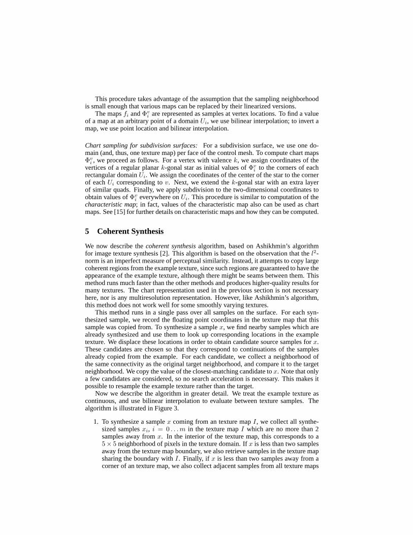
This method runs in a single pass over all samples on the surface. For each syn-thesized sample, we record the floating point coordinates in the texture map that thissample was copied from. To synthesize a sample x, we find nearby samples which arealready synthesized and use them to look up corresponding locations in the exampletexture. We displace these locations in order to obtain candidate source samples for x.These candidates are chosen so that they correspond to continuations of the samplesalready copied from the example. For each candidate, we collect a neighborhood ofthe same connectivity as the original target neighborhood, and compare it to the targetneighborhood. We copy the value of the closest-matching candidate to x. Note that onlya few candidates are considered, so no search acceleration is necessary. This makes itpossible to resample the example texture rather than the target.
Now we describe the algorithm in greater detail. We treat the example texture ascontinuous, and use bilinear interpolation to evaluate between texture samples. Thealgorithm is illustrated in Figure 3.
1. To synthesize a sample x coming from an texture map I , we collect all synthe-sized samples xi, i = 0 . . . m in the texture map I which are no more than 2samples away from x. In the interior of the texture map, this corresponds to a5× 5 neighborhood of pixels in the texture domain. If x is less than two samplesaway from the texture map boundary, we also retrieve samples in the texture mapsharing the boundary with I . Finally, if x is less than two samples away from acorner of an texture map, we also collect adjacent samples from all texture maps
texture maps Ii example texturesurface f
ei
xi'
di
v2 v1
'yi
xi x
Fig. 3. Coherence synthesis. In order to synthesize a texture value for a point x, we examineeach of its already-synthesized neighbors xi (filled circles). In the figure, we show a point xthat occurs at a “corner” where five texture maps meet on the surface. (The open circles indicateunsynthesized pixels, which are ignored during this step.) Each neighbor proposes a candidatelocation y′
i from the example, based on its own location in the example and its distance fromx on the surface. Each y′
i corresponds to the texture location for x if we were to continue thetexture patch used for xi to x. The best candidate is computed by comparing the candidateneighborhoods with l2.
sharing the corner. If no synthesized samples are located, a random value fromthe example texture is selected.
2. For each collected sample xi, we compute the 3D displacement di = f(xi) −f(x) to the target surface point, and project di into the tangent plane at f(x) toobtain tangent displacements dt
i. The tangent displacements can be representedin the local coordinate system (v1, v2) by 2D vectors ei: dt
i = e1i v1 + e2
i v2.3. Our next goal is to locate candidate locations for x in the example texture. For
each of the neighboring samples xi, we look up the corresponding location x′i
in the example texture. We use these samples to generate candidate locationsy′
i = x′i − ei, i.e. by looking up the value which is located in the example in
the same way with respect to x′i as x is with respect to xi. Note that, unlike in
Ashikhmin’s method, the location and the displacement should be represented asfloating point numbers in order to prevent errors due to round-off.
4. Now we need to choose which of the candidates is used to get the value for thetarget. To do this, we compare neighborhoods of y′i with the neighborhood ofx. We use the same set of displacements ei to get samples around y′
i whichare arranged in the same pattern as xi around x, i.e. we consider neighborhoodsN(y′
i) consisting of samples y′ij = y′
i + ej . Undefined values are discarded whenthe distance is computed. Among these neighborhoods we choose the one forwhich the l2 distance from the the neighborhood of x is minimal
6 Experiments
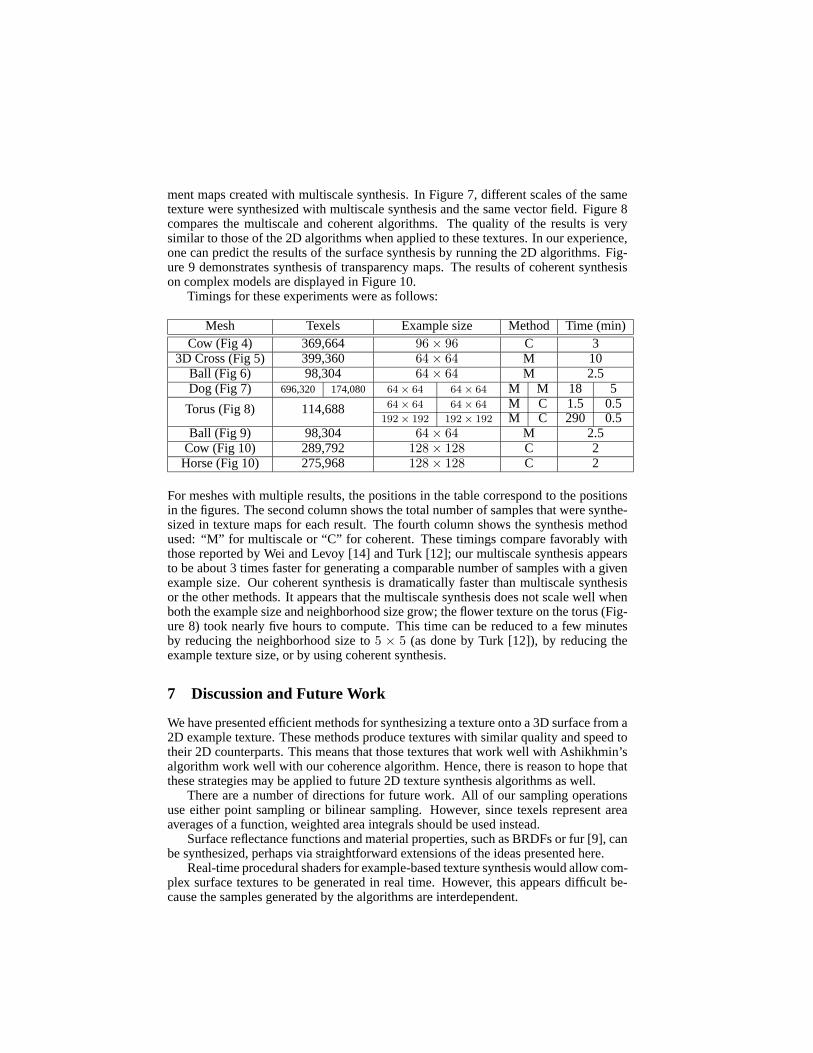
In Figure 4, we demonstrate coherent synthesis of a nut texture on a cow model. Notethat the texture maps appear distorted, because they are synthesized to appear undis-torted on the surface. With coherent synthesis, the texture has high quality, but somesmall discontinuities are visible. Figures 5 and 6 show the transparency and displace-
ment maps created with multiscale synthesis. In Figure 7, different scales of the sametexture were synthesized with multiscale synthesis and the same vector field. Figure 8compares the multiscale and coherent algorithms. The quality of the results is verysimilar to those of the 2D algorithms when applied to these textures. In our experience,one can predict the results of the surface synthesis by running the 2D algorithms. Fig-ure 9 demonstrates synthesis of transparency maps. The results of coherent synthesison complex models are displayed in Figure 10.
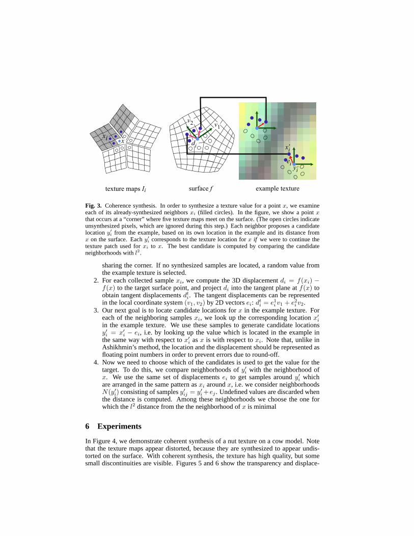
Timings for these experiments were as follows:
Mesh Texels Example size Method Time (min)Cow (Fig 4) 369,664 96 × 96 C 3
3D Cross (Fig 5) 399,360 64 × 64 M 10Ball (Fig 6) 98,304 64 × 64 M 2.5Dog (Fig 7) 696,320 174,080 64 × 64 64 × 64 M M 18 5
64 × 64 64 × 64 M C 1.5 0.5Torus (Fig 8) 114,688192 × 192 192 × 192 M C 290 0.5
Ball (Fig 9) 98,304 64 × 64 M 2.5Cow (Fig 10) 289,792 128 × 128 C 2
Horse (Fig 10) 275,968 128 × 128 C 2
For meshes with multiple results, the positions in the table correspond to the positionsin the figures. The second column shows the total number of samples that were synthe-sized in texture maps for each result. The fourth column shows the synthesis methodused: “M” for multiscale or “C” for coherent. These timings compare favorably withthose reported by Wei and Levoy [14] and Turk [12]; our multiscale synthesis appearsto be about 3 times faster for generating a comparable number of samples with a givenexample size. Our coherent synthesis is dramatically faster than multiscale synthesisor the other methods. It appears that the multiscale synthesis does not scale well whenboth the example size and neighborhood size grow; the flower texture on the torus (Fig-ure 8) took nearly five hours to compute. This time can be reduced to a few minutesby reducing the neighborhood size to 5 × 5 (as done by Turk [12]), by reducing theexample texture size, or by using coherent synthesis.
7 Discussion and Future Work
We have presented efficient methods for synthesizing a texture onto a 3D surface from a2D example texture. These methods produce textures with similar quality and speed totheir 2D counterparts. This means that those textures that work well with Ashikhmin’salgorithm work well with our coherence algorithm. Hence, there is reason to hope thatthese strategies may be applied to future 2D texture synthesis algorithms as well.
There are a number of directions for future work. All of our sampling operationsuse either point sampling or bilinear sampling. However, since texels represent areaaverages of a function, weighted area integrals should be used instead.
Surface reflectance functions and material properties, such as BRDFs or fur [9], canbe synthesized, perhaps via straightforward extensions of the ideas presented here.
Real-time procedural shaders for example-based texture synthesis would allow com-plex surface textures to be generated in real time. However, this appears difficult be-cause the samples generated by the algorithms are interdependent.
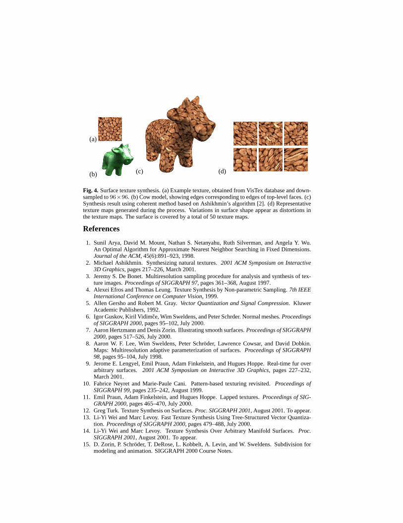
(a)
(b) (c) (d)
Fig. 4. Surface texture synthesis. (a) Example texture, obtained from VisTex database and down-sampled to 96×96. (b) Cow model, showing edges corresponding to edges of top-level faces. (c)Synthesis result using coherent method based on Ashikhmin’s algorithm [2]. (d) Representativetexture maps generated during the process. Variations in surface shape appear as distortions inthe texture maps. The surface is covered by a total of 50 texture maps.
References
1. Sunil Arya, David M. Mount, Nathan S. Netanyahu, Ruth Silverman, and Angela Y. Wu.An Optimal Algorithm for Approximate Nearest Neighbor Searching in Fixed Dimensions.Journal of the ACM, 45(6):891–923, 1998.
2. Michael Ashikhmin. Synthesizing natural textures. 2001 ACM Symposium on Interactive3D Graphics, pages 217–226, March 2001.
3. Jeremy S. De Bonet. Multiresolution sampling procedure for analysis and synthesis of tex-ture images. Proceedings of SIGGRAPH 97, pages 361–368, August 1997.
4. Alexei Efros and Thomas Leung. Texture Synthesis by Non-parametric Sampling. 7th IEEEInternational Conference on Computer Vision, 1999.
5. Allen Gersho and Robert M. Gray. Vector Quantization and Signal Compression. KluwerAcademic Publishers, 1992.
6. Igor Guskov, Kiril Vidimce, Wim Sweldens, and Peter Schrder. Normal meshes. Proceedingsof SIGGRAPH 2000, pages 95–102, July 2000.
7. Aaron Hertzmann and Denis Zorin. Illustrating smooth surfaces. Proceedings of SIGGRAPH2000, pages 517–526, July 2000.
8. Aaron W. F. Lee, Wim Sweldens, Peter Schroder, Lawrence Cowsar, and David Dobkin.Maps: Multiresolution adaptive parameterization of surfaces. Proceedings of SIGGRAPH98, pages 95–104, July 1998.
9. Jerome E. Lengyel, Emil Praun, Adam Finkelstein, and Hugues Hoppe. Real-time fur overarbitrary surfaces. 2001 ACM Symposium on Interactive 3D Graphics, pages 227–232,March 2001.
10. Fabrice Neyret and Marie-Paule Cani. Pattern-based texturing revisited. Proceedings ofSIGGRAPH 99, pages 235–242, August 1999.
11. Emil Praun, Adam Finkelstein, and Hugues Hoppe. Lapped textures. Proceedings of SIG-GRAPH 2000, pages 465–470, July 2000.
12. Greg Turk. Texture Synthesis on Surfaces. Proc. SIGGRAPH 2001, August 2001. To appear.13. Li-Yi Wei and Marc Levoy. Fast Texture Synthesis Using Tree-Structured Vector Quantiza-
tion. Proceedings of SIGGRAPH 2000, pages 479–488, July 2000.14. Li-Yi Wei and Marc Levoy. Texture Synthesis Over Arbitrary Manifold Surfaces. Proc.
SIGGRAPH 2001, August 2001. To appear.15. D. Zorin, P. Schroder, T. DeRose, L. Kobbelt, A. Levin, and W. Sweldens. Subdivision for
modeling and animation. SIGGRAPH 2000 Course Notes.

(a) (b) (c)
Fig. 5. (a) Surface with orientation field. Note the singularity of the field at the top of the model.(b) Synthesized texture using multiscale synthesis of the first texture from Figure 8 in grayscale.The texture appears consistent at the singularity. (c) Texture mapping and displacement mappingwith the same texture.
(a) (b) (c) (d)
Fig. 6. Textured sphere generated with multiscale synthesis. (a) Example texture. (b) Syn-thesized texture. (c) Texture mapping plus transparency mapping (using the same texture). (d)Displacement mapping.
Fig. 7. Zebra dog, generated with multiscale synthesis. Varying the scale parameter creates atexture with a different size on the surface.

Examples Multiscale synthesis Coherent synthesis
Fig. 8. Comparison of multiscale (based on Wei-Levoy [13]) and coherent algorithms (based onAshikhmin [2]). The results are comparable to those of the image texture synthesis algorithms.
Fig. 9. Transparency mapping. Left: Example textures. Middle: Wicker ball, generated fromfirst texture by multiscale synthesis. Right: Bronze cow, generated by coherent synthesis fromsecond texture blended with a green surface color.
Fig. 10. Chia cow and sea horse, generated with coherent synthesis.