texas instruments innovation challenge: europe design
TRANSCRIPT

Texas Instruments Innovation Challenge: Europe Design Contest 2015 Project Report
Piezoelectric deformable mirror
Team Leader: Jaka Pribošek [email protected]
Team Members: Team Matija Brumat, [email protected]
Advising Professor: Prof. dr. Janez Diaci, [email protected]
University: University of Ljubljana, Slovenia
Date: 31.7.2015
Qty. TI Part Number & URL Qty. TI Part Number & URL
1 MSP430F5529LP 1 LMZ35003
1 DAC8734 1 LMZ34002
1 ISO7240C 2 TPS7A4701
4 OPA454 1 TPS7A3301
1 REF02 2 UC3525A
1 UA78L05
Project abstract: The report outlines the development of low cost deformable mirror system for high precision beam steering applications. We present complete instructions how to fabricate and assemble piezoelectric deformable mirror as well as detailed description of applied analog design principles used in piezo driver and required power supply units. The driver consists of microprocessor controlling DAC whose output is amplified through HV amplifier. This way, four channel piezo mirror is powered up to 93 Vp-p at 16 bit resolution and fast 75000 points/second performance. Excellent system performance in terms of accuracy and linearity has been found. The beam steering performance was verified in a prototype optical instrument. As a result, the TI logo smaller than thickness of a human hair has been drawn with a laser.

1. Introduction and motivation According to the World Health Organization, 90% of the world's visually impaired population live in countries with lower social-economic standard. Effective early diagnose of glaucoma (causing blindness), can only be achieved by an adaptive retinal ophthalmoscope capable of imaging through aberrant eyes. Similarly, aberrations induced by air turbulences limit the astronomers from seeing the details in deep space. Opposite in scale, imaging of the smallest details at microscopic levels has not been possible until Nipkow spinning disc microscopes appeared. Other complicated alternative beam steering concepts such as Risley prisms or Acoustooptical Deflectors are exploited to manipulate atoms using optical tweezers, fabricate next generation lab-on-chips using laser lithography or burn malignant cells using high-end endoscopic laser scalpels in minimal invasive surgeries. Despite the diversity of the aforementioned applications, they are all unified by the need for fast and precise light manipulation. We present a design concept that opens a flexible alternative to suit all those needs – an ultralow cost piezoelectric deformable mirror. Such inexpensive mirrors may open the access to high quality ophthalmoscopes for doctors in rural areas and third world countries. Further on, such mirrors can upgrade homemade telescopes of amateur astronomers to allow better observation of the planets in our universe. They can simplify and lower the cost of laser steering in the most demanding applications– they may change the design of optical tweezers and lower the complexity of laser scanning microscopes. Such mirrors open possibilities of wavefront control in laser interference lithography in order to fabricate the tinniest details at submicron levels. At fabrication costs of only few dollars, they offer an excellent disposable solution in minimal invasive laser surgery in order to avoid sterilization and thereby minimize time and costs. The beauty of it is that fabrication of both the piezoelectric deformable mirror and the mirror control electronics may be easily accomplished at home, even without access to high-tech equipment. Thanks to the integrated solutions of Texas Instruments, the big potential of deformable mirrors is now opened to many enthusiasts worldwide. So go, be creative and revolutionize the world!
2. Theoretical background The deformable mirror is a composite device of thin metal diaphragm, with layer of piezo ceramics on the back side and thin front-surface mirror on the front side. In such design, a diaphragm itself is common to all electrodes, what enforces the need for a single ended ground referenced excitation. Applying high positive voltage to piezo ceramics deforms the diaphragm and forms a diverging output beam (Fig.1A).
Figure 1: Concept of deformable mirror – beam focusing (A,B) and steering (C,D,E)
By reversing the voltage mirror deforms to a convex shape forming a converging output beam (Fig.1B). In case of segmented electrodes, varying voltage amplitudes between segments enforces different local curvatures of the diaphragm in a such way that two additional in-plane mirror rotations are feasible (Fig.1 C & D). Voltage
differences between left and right channels result in deflection of laser beam in X direction, and differences between channels upper and lower channel deflects the laser in Y direction. This allows a combined deflection (Fig1. E) by a superposition of
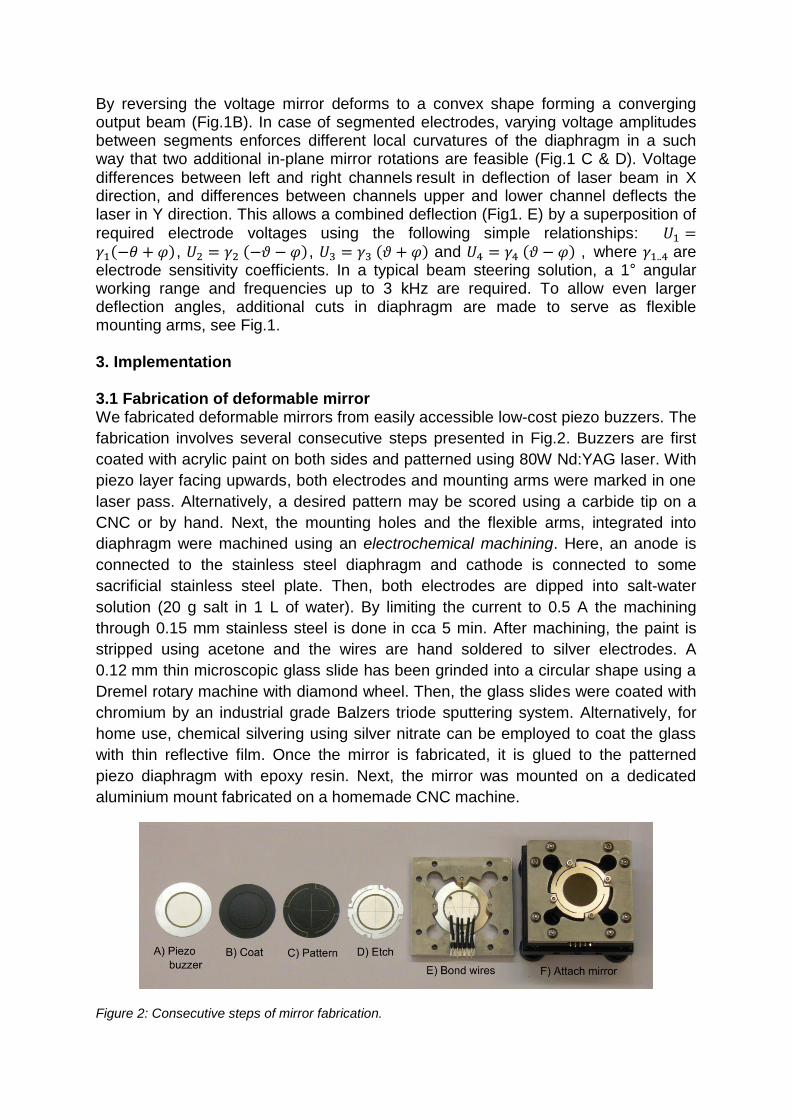
required electrode voltages using the following simple relationships: 𝑈1 =𝛾1(−𝜃 + 𝜑), 𝑈2 = 𝛾2 (−𝜗 − 𝜑), 𝑈3 = 𝛾3 (𝜗 + 𝜑) and 𝑈4 = 𝛾4 (𝜗 − 𝜑) , where 𝛾1..4 are electrode sensitivity coefficients. In a typical beam steering solution, a 1° angular working range and frequencies up to 3 kHz are required. To allow even larger deflection angles, additional cuts in diaphragm are made to serve as flexible mounting arms, see Fig.1. 3. Implementation 3.1 Fabrication of deformable mirror We fabricated deformable mirrors from easily accessible low-cost piezo buzzers. The
fabrication involves several consecutive steps presented in Fig.2. Buzzers are first
coated with acrylic paint on both sides and patterned using 80W Nd:YAG laser. With
piezo layer facing upwards, both electrodes and mounting arms were marked in one
laser pass. Alternatively, a desired pattern may be scored using a carbide tip on a
CNC or by hand. Next, the mounting holes and the flexible arms, integrated into
diaphragm were machined using an electrochemical machining. Here, an anode is
connected to the stainless steel diaphragm and cathode is connected to some
sacrificial stainless steel plate. Then, both electrodes are dipped into salt-water
solution (20 g salt in 1 L of water). By limiting the current to 0.5 A the machining
through 0.15 mm stainless steel is done in cca 5 min. After machining, the paint is
stripped using acetone and the wires are hand soldered to silver electrodes. A
0.12 mm thin microscopic glass slide has been grinded into a circular shape using a
Dremel rotary machine with diamond wheel. Then, the glass slides were coated with
chromium by an industrial grade Balzers triode sputtering system. Alternatively, for
home use, chemical silvering using silver nitrate can be employed to coat the glass
with thin reflective film. Once the mirror is fabricated, it is glued to the patterned
piezo diaphragm with epoxy resin. Next, the mirror was mounted on a dedicated
aluminium mount fabricated on a homemade CNC machine.
Figure 2: Consecutive steps of mirror fabrication.

3.2 System architecture Generally, a curvature of a bimorph piezo actuator is proportional to amplitude of applied voltage. To achieve deflections that deform the surface of the mirror to an useful degree, several tens of volts may be necessary. Fast driving of capacitive loads is governed by equation of electrical reactance given by 𝑥𝑐 = 1/(2𝜋𝑓𝐶), which for piezo buzzers used in our design (resonant frequency at f=3.5 kHz and C=60 nF) results in 760 Ω. Solely driving this load at 3.5 kHz and 100 Vp-p amplitudes requires a 3.3 W HV power supply, not including quiescent currents of the amplifier and supply itself. Conventional bipolar switching designs regulate only positive voltage where negative remains unregulated. Using such power supply in an asymmetrically loaded application may result in swinging output voltage at the unregulated rail which can easily damage the HV amplifier. To solve this, a regulation of both rails is required. For this purpose a custom HV split-rails switching converter is developed based on two separate UC3525A in a push-pull topology.
Figure 2: Complete system architecture
To drive a piezoelectric actuator, integrated haptic drivers such as DRV8662 or DRV2700 would normally be a preferred choice as they simplify the design with their integrated boost converter and easy-to-use interfaces. Unfortunately, bimorph deformable mirror enforces a single ended ground referenced architecture, which prevents the use of differential architecture as used in DRV series drivers. Instead, we used a bipolar DAC to generate required signals and amplify the signals by an additional high voltage amplifier. Optimal design solution has been found by a combination of quad channel precision DAC8734, offering 16 bit resolution and ±10 V signal amplitude, fast SPI interface and synchronous channel update, with OPA454 offering 50 mA output at widest output voltage swing in their class. This way fast, precise and stable operation is guaranteed by choosing the appropriate TI components. To maintain a 16 bit output precision, an ultra-low noise ±12 V power supply is required to power DAC. We used a regulated split-rail buck converter built with LMZ35003 and LMZ34002 power modules to lower the input voltage at ±13 V. Each rail is then regulated by ultra-low noise LDOs (TPS7A4701 and TPS7A3301 for positive and negative rail respectively) in order to provide optimal voltage stability for precision DAC. Finally, to prevent any possible damage, a galvanic isolation of 4 SPI data lines is employed – due to high frequency signals (24 MHz Clock) a high speed capacitive digital isolator ISO7240C was used. A chosen heart of the piezo driver is MSP430F5529 Launchpad due to 24 MHz

clock, high speed USB, plenty of powerful timers, DMA features, JTAG debug capabilities and most of all an extremely steep learning curve thanks to numerous examples provided by TI. Lastly, Mathworks Matlab was chosen as a primary platform throughout the development stage, as it allows data acquisition, signal generation and analysis under the same roof. As such, plenty of room for further research towards numerical modelling is left opened. 3.2.1 High voltage push-pull converter To avoid troubles due to asymmetric loads, as discussed in chapter 3.2, a split-rail DC-DC power supplies based on two TI UC3525A regulators in a push pull design topologies was built. We chose an operating frequency of a 20 kHz, for which a ferrite pot-core custom transformer with 2.08 ratio (50 V/24 V=2.08) was designed and built. Both coils are made from CuL 0.35 mm² wire to suit the general rule of a thumb 3 A/mm². The number of primary wounds is given by an equation 𝑁 = (𝑈𝑝𝑟𝑖𝑚𝑎𝑟𝑦104)/(𝐾𝑓𝐵𝑚𝑎𝑥𝑓 𝐴𝑒) with 𝐾𝑓 = 4 for square wave signals, 𝐴𝑒 for Ø26x16
pot-core is 94 mm² and 𝐵𝑚𝑎𝑥 set as 0.15 T. We thus wound 11 bifilar wounds on primary and 28 bifilar wounds on secondary side to suit the voltage ratio and account for 20 % output voltage reserve for PWM and voltage drops. 100 V IRF540 N-
channel MOSFET transistors with low 𝑅𝑑𝑠𝑂𝑁 = 40 𝑚 Ω are used. A 12 V Zener is used to drop 𝑉𝐶 and keep the FET's 𝑉𝑔𝑠 voltage under 20 V. A 10 uF capacitor
provides soft start in 0.5 s. Ultra-fast rectifying diodes UF4007 and low pass LC filter
(L1 and C16) with a cut-off frequency at 1
2𝜋√𝐿𝐶= 112 𝐻𝑧 serve for smooth DC output
voltage.
Figure 3 : Push-pull positive voltage rail
Conceptually, a negative rail is similar to the positive one presented in Fig.3. In order
to trick the UC3525A to control a negative output, an unconventional solution is
made at the input of the error voltage amplifier (Fig.4). A voltage divider (R12, R25,
R26) is used to apply 3 V bias to the negative feedback input. Positive input is
biased at 5.1 V through R24 which allows the UC3525A to start. Negative feedback,
which drives inputs of error amplifier in equilibrium, is provided by R27. The PCB
was organized symmetrically for both rails. Massive ground plane was created, and
higher loaded traces have been kept 100 mils wide. HV push-pull power supply was

designed as a single sided PCB, so it can be easily fabricated at home. Here, a
combination of 0805 SMD components and through-hole components was found to
be an ideal solution for creation of small footprint PCB and lower the number of air-
wires (Fig 4: right).
Figure 4: Negative voltage rail design variation at the input of error voltage amplifier (left), and
complete PCB layout of a converter (right).
3.2.2 Split-rail buck converter
First, to prevent any possible damage, the design involves a simple safety circuit
including input overvoltage and polarity protection. This is implemented by a P-FET
followed by a 2 W 36 V Zener diode (Fig.5 A).
.
Figure 5: Schematic and layout of split-rail buck converter with marked: (A) Input voltage amplitude
and reverse polarity protection circuit, B) Positive rail C) Negative rail.
The 24 VDC input voltage is then passed to a high performance regulated split-rail
buck converter. Highly integrated LMZ34002 and LMZ35003 “Simple switchers™”
modules were used to generate ±12.7 V. They were chosen in favour of minimal
number of external components, easy design and extremely small footprint. We
optimized the switching design components using a WEBENCH designer, which
served for initial design. To achieve optimal electrical and thermal performances,
special care was given to maintain a proper PCB layout (Fig.5 right) – we used large

copper areas for power planes and multiple vias in order to minimize conduction
losses and thermal stress. Low ESR tantalum capacitors were chosen and placed as
close to the module pins as possible, in order to attenuate high frequency noise.
Special attention was paid to the connection of analog and digital grounds at a single
point – at pins 8 and 9. Output of the switching power supplies is further regulated by
ultra-low noise LDOs TPS7A4701 and TPS7A3301. Low ESR Tantalum capacitors
were used near the ICs. By exploiting combination of integrated switcher and low-
noise LDO, we came out with a highly integrated high performance power supply
required for precision DAC power supply.
3.2.3 DAC and HV amplifier
The initial idea of piezo beam steering has first been tested using an DAC8734EVM
evaluation board. After initial tests, we carefully studied the design of the EVM board
and followed the same system concept in our design. In order to protect SPI
communication lines, a capacitive galvanic isolation ISO7240C is used to
accommodate for unidirectional isolation of CLK, CS, SDI and LATCH signals.
100 nF Tantalum capacitors were placed as close as possible to device terminals.
At the isolated side, an additional UA78L05 was added to provide a logic level for
both isolator and DAC.
Figure 6: DAC design (Please note that two opamps are omitted on the schematic).
The DAC8734 is referenced by a 5.00 V low-noise precision voltage reference
REF02 supplied from 12 V positive rail. Bipolar ultralow noise ±12 V split-rail power
supply is used in order to provide enough power for ±10 V output voltage swing.
Transient voltage suppression diodes were added on the DAC outputs in order to
protect DAC during slewing. The PCB layout of a precision DAC has to be done very
carefully, if a good 16 bit precision is desired. Multiple vias were placed under the
DAC to assure good grounding. We kept digital lines only 10 mils wide, whereas
power planes were kept as wide as possible, with closely placed capacitors. At both
rails, 100 nF ceramic capacitors parallel to 10 uF low ESR Tantalum capacitors are

placed against ground. Output channel lines were kept 25 mils wide in order to
minimize voltage drops due to resistance.
The generated signals are fed to 4 channel HV amplifier. Here, 100 Vp-p OPA454
were chosen for being the highest voltage opamps available at the market and
capable of up to 50 mA output current, enough to power piezoelectric mirrors. At
power rails two additional 51 V protection Zener diodes suppress potential
overvoltages. The opamps are wired as negative feedback amplifiers, with gain set
as -𝑅𝐹
𝑅𝑖= −4.66. Apart of using 1% resistors to minimize channel differences, their
resistance were measured and the resistor pairs were first bench-tested and
matched. Parallel to a feedback resistor, a 10pF capacitor was planned to limit the
bandwidth, but was later found to be superfluous and was not added in final design.
3.2.3 Microcontroller and software
Position instructions are provided by a host computer running MathWorks Matlab. A
necessary trajectory is generated and coordinates of desired geometry are sent over
a high bandwidth USB interface using a custom protocol to a MSP430F5529
Launchpad. The MSP430 decodes the instructions, transforms the geometry to
electrode voltages and sends it to DAC over a 24 MHz SPI. Two different system
modes are implemented – asynchronous mode is used for instant responses to input
instructions, where DAC update is executed as soon as the electrode voltages are
updated from the instruction decoder input. For smoother beam steering along a
predefined curve, synchronous mode is preferred. Here, instructions are first
decoded and fed to a FIFO buffer. They are executed on Timer interrupt, triggered
every 12 µs. In a Timer ISR, the trajectory is iteratively interpolated in order to lower
the number of required input coordinate and to decrease time spent on USB
communication and instructions decoding. For this a fast iterative Bresenham
interpolation algorithm was implemented. We ended up with a system design
capable of high speed performance of 75000 updates/sec.
Figure 7: Software architecture

4. Final application
Fig.8 shows individual system units and their integration into a prototype optical
setup, built to verify the system performance. In setup a laser diode passing through
linear polarizer and polarizing beam splitter illuminates the deformable mirror
mounted at one arm of the system. The light bounces off the mirror and falls on a
CMOS sensor of a camera mounted at the other side.
Figure 8: Individual system units (Left), Integration of the deformable mirror into an optical instrument
prototype (Right)
The exact pixel size of a CMOS sensor (3.63 μm for Sony IMX035) allows precise
spatial measurements of laser beam position. The camera and detection algorithm is
capable of 120 Hz image streams, which was found enough for testing quasistatic
and slow dynamic system performance. Unfortunately this measurement technique
does not allow us to study the higher system dynamics, including mirror resonance
behaviour.
5. Experimental results
First, the electrical system response
under load was measured. A reference
signal of 23 V amplitude was set on
output of a piezo amplifier, and voltage
response on piezo actuator has been
acquired (Fig.9). The output voltage
settles in 5 µs, overshoots less than
1.5 V and remains stable afterwards.
Next what interests us the most, is the
linearity of the deformable mirror system.
Surprisingly, the deformable mirror
exhibit perfect linear performance with Figure 9: Electrical system response (shown in green)
and trigger signal (shown in violet)

sensitivity coefficient measured to be γ = 0.022 mrad/V and nonlinearities lower
than 0.9 mrad over the whole working range of ±0.63°. The nonlinearities mainly
result from piezo hysteresis but remain under critical values. Since the deflection
angles are small, the linearity is maintained even after the deflected light passes
through the focusing optics. The focusing optics provides sharp focus and magnifies
the working area to 120x120 μm. To demonstrate system capabilities a TI logo
smaller than thickness of a human hair has been drawn with a laser. First, an
automatic edge detection algorithm was used to trace the geometry of the logo from
a bitmap picture. The desired geometry consisting of 475 points was sent over to
MSP430 where required voltages for each electrode were calculated and generated
for each point. The CMOS sensor was used to measure the beam position. Fig. 10
shows the end results - the desired logo is smaller than a human hair; exploiting the
limits of the employed measurement technique.
Figure 10 : Desired (left) and measured trajectory of laser beam (in the middle), steered by presented
deformable mirror system. Human hair serves for size comparison (right).
5. Conclusion
The system performances exceeded all our initial expectations. Good system
linearity and astonishing submicron steering capabilities have been demonstrated at
75 kpps speeds, which is opening numerous application possibilities.
6. Summary This report outlines the development of an affordable high precision beam steering based on the principles of piezoelectric deformable mirror. Using TI’s solutions, we were able to develop a high-tech device from scratch in an extremely short time period. During the design stage, TI’s evaluation boards turned out to be the fastest way to test and bring the novel ideas to life. Next, the design was optimized and key components were found by exploiting a Webench designer. Device datasheets were found full of useful instructions and hints for a good layout. Finally, the Code Composer Studio with numerous useful code examples provided good base to start coding and bring the system to life. 7. Future plans Beside further system improvements and testing, our future plans point towards integration of the deformable mirror system into a precision scanning confocal microscope, aimed for measuring 3D topography of microstructures.

Bill of materials Value Quantity Package Manufacturer
R10 4 R0805 Multicomp R27 2 R0805 Multicomp R220 1 R0805 Multicomp R390 1 R0805 Multicomp R1k 5 R0805 Multicomp R1.8k 2 R0805 Multicomp R3.3k 2 R0805 Multicomp C4.7k 2 R0805 Multicomp C20k 2 R0805 Multicomp C10n 4 C0805 Murata C47n 2 C0805 Murata C100n 2 C0805 Murata CP10u 5 B/3528-21R Kemet CP100uF 63V 4 E5-10.5 Jamicon CP470u 50V 2 E5-10.5 Jamicon Zener 12V 2 DO34Z7 Panasonic DZ436000 1 SMB Panasonic Fuse F800mA 1
Littelfuse
8.22mH 2 822J Fastron IRF540 4 TO220 International rectifier UF4007 4 DO41 Fairchild semiconductors UC3525A 2 DIP16 Texas Instruments Connector 3 2 pin Wago Transformer 2.08 2 Ø26x26 Custom build R1k 1 R0805 Multicomp R2.2k 1 R0805 Multicomp R10k 2 Trimmer BOURNS R12k 4 R0805 Multicomp R18k 1 R0805 Multicomp R56k 4 R0805 Multicomp R62k 2 R0805 Multicomp R100k 1 R0805 Multicomp R150k 2 R0805 Multicomp R220k 1 R0805 Multicomp C10p 4 C0805 Murata C10n 1 C0805 Murata C100n 22 C0805 Murata C1u 4 B/3528-21R Kemet C4.7u 2 B/3528-21R Kemet C10u 2 EU153CLV Panasonic C22u 1 EU153CLV Panasonic IRF9530 1 T020 International rectifier T12C 4 SOD323 Bourns DZ436000 1 SMB Panasonic BZV55-C 51V 2 SOD80C NXP REF02D 1 SOIC8 TexasInstruments UA78L05 1 SOT89 TexasInstruments ISO7240C 1 SO-16Dw TexasInstruments TPS7A4701 1 QFN65P Texas Instruments TPS7A3301 1 QFN65P Texas Instruments LMZ34002 1 QFN41P TexasInstruments LMZ35003 1 QFN41P TexasInstruments DAC8734 1 QFP50P Texas Instruments OPA454 4 SOIC127 Texas Instruments Connector 3 3-pin Wago