tetra tech, inc. - us epa
TRANSCRIPT

Tetra Tech, Inc. 2768 Compass Dr. Suite 200, Grand Junction, CO 81506
Tel 970.986.3566 www.tetratech.com
April 24, 2020 Ms. Claudia Young Smith U.S. EPA Region 8 1595 Wynkoop Street Mail Code 8ARD-PM Denver, Colorado 80202 Re: Revised Federal Minor New Source Review Program in Indian Country, 40 CFR 49.151 Application for New Construction for the Cottonwood Mine in Uintah County, Utah Dear Claudia: On behalf of American Gilsonite Company (AGC), Tetra Tech, Inc. (Tetra Tech) is submitting this revised Federal Minor New Source Review Program in Indian Country, 40 CFR 49.151 Application for New Construction. This revised application replaces the Application for New Construction submitted on February 28, 2020. The revisions include:
1. The permit application is for Proposed Construction of New Equipment at an Existing Source and Proposed Modification of an Existing Source. The box for Proposed Construction of a New Source is not checked.
2. The emissions have been calculated for the following scenarios: a. Current actual emissions using 2019 operating hours and production for CW-3 and CW-6 (non-
tiered engine); b. Current allowable emissions using 8,760 operating hours and calculated maximum production
for CW-3 and CW-6; c. Post Change Potential Emissions for CW-3, CW-6 (Tier 4), Tier 4 Primary Engine (CW-7) and Tier
4 Mine Dewatering Engine using 8,760 operating hours and a calculated annual production; d. Post Change Allowable Emissions for the engines in sub bullet 2c using 4,524 hours for the
primary engines and 8,760 hours for the mine dewatering engine. The annual production is 20,000 tons.
3. In Section E Table of Estimate Emissions Table E (i) is blank and Table E(ii) contains the estimated emissions.
4. Attachment D has been revised to add the updated emissions calculations, explain the methodology to calculate the annual production for emissions calculations using 8,760 hours and describe the change in

Revised Application for New Construction for Cottonwood Mine April 24, 2020
2 Tetra Tech, Inc.
emissions. The basis for the annual production rate is discussed in Attachment D.2 Cottonwood Mine Plan.
5. Attachment D.4.1 contains the emissions factors and revised emissions calculations for the scenarios described in Bullet 2.
6. Emission calculations have been updated to reflect the manufacturer guaranteed grain loading from the baghouses.
Thank your input in preparing this permit revision. Please contact me at [email protected] or 970-260-1655 if you have any questions or need additional information. Sincerely Tetra Tech, Inc.
William P. Balaz Jr., PE Project Manager Attachment: Revised Application for New Construction for Cottonwood Mine with Attachments Cc: Colin Schwartz, EPA Region 8 Scott Patefield, EPA Region 8 Alex North, EPA Region 8 CDX eDisclosure Nick Lott, AGC Mike Wilhite, AGC Sara Lubchenco-Burson, Tetra Tech, Inc.

OMB Control No. N/A
Page 1 of 7
UNITED STATES ENVIRONMENTAL PROTECTION AGENCY FEDERAL MINOR NEW SOURCE REVIEW PROGRAM IN INDIAN
COUNTRY 40 CFR 49.151
Revised Application for New Construction (Form NEW)
Reviewing A
Please check all that apply to show how you are using this form: ϒ Proposed Construction of a New Source X Proposed Construction of New Equipment at an Existing Source X Proposed Modification of an Existing Source ϒ Other – Please Explain
Use of this information request form is voluntary and not approved by the Office of Management and Budget. The following is a check list of the type of information that Region 8 will use to process information on your proposed project. While submittal of this form is not required, it does offer details on the information we will use to complete your requested approval and providing the information requested may help expedite the process. An application form approved by the Office of Management and Budget can be found online at https://www.epa.gov/sites/production/files/2015-12/documents/new_source_general_application_rev2017.pdf. Please submit information to following two entities: Federal Minor NSR Permit Coordinator Air and Radiation Division U.S. EPA, Region 8 1595 Wynkoop Street, 8ARD-PM Denver, CO 80202-1129 [email protected]
The Tribal Environmental Contact for the specific reservation: If you need assistance in identifying the appropriate Tribal Environmental Contact and address, please contact: [email protected]
For more information, visit: http://www.epa.gov/caa-permitting/tribal-nsr-permitting-region-8 A. GENERAL SOURCE INFORMATION
1. (a) Company Name American Gilsonite Company (b) Operator Name American Gilsonite Company
2. Facility Name American Gilsonite Company, Cottonwood Mine Site
3. Type of Operation Gilsonite Ore Mining
4. Portable Source? Yes No 5. Temporary Source? Yes No
6. NAICS Code 212399 – All other nonmetallic mineral mining
7. SIC Code 1499 – Miscellaneous nonmetallic minerals, except fuels
8. Physical Address (Or, home base for portable sources) 29950 S. Bonanza Hwy., Bonanza, Utah 84008 (office location)
9. Reservation* CW# 1: Uintah and Ouray CW# 2: Uintah and Ouray CW# 3: Uintah and Ouray CW# 4: Uintah and Ouray CW# 5: Uintah and Ouray CW# 6: Uintah and Ouray CW# 7: Uintah and Ouray
10. County* CW# 1: Uintah CW# 2: Uintah CW# 3: Uintah CW# 4: Uintah CW# 5: Uintah CW# 6: Uintah CW# 7: Uintah
11a. Latitude (decimal format)* CW# 1: 39.899544° CW# 2: 39.900667° CW# 3: 39.898252° CW# 4: 39.903061° CW# 5: 39.904699° CW# 6: 39.897441°
11b. Longitude (decimal format)* CW# 1: -109.519913° CW# 2: -109.523920° CW# 3: -109.515233° CW# 4: -109.532772° CW# 5: -109.538394° CW# 6: -109.512153°

Page 2 of 7
CW# 8: Uintah and Ouray CW# 8: Uintah CW# 7: 39.896700° CW# 8: 39.904025°
CW# 7: -109.509507° CW# 8: -109.535921°
12a. Quarter Quarter Section* CW# 1: SE ¼, SW ¼ CW# 2: NW ¼, SW ¼ CW# 3: SW ¼, SE ¼ CW# 4: NW ¼, SE ¼ CW# 5: SE ¼, NW ¼ CW# 6: SE ¼, SE ¼ CW# 7: SE ¼, SE ¼ CW# 8: SW ¼, NE ¼
12b. Section* CW# 1: 35 CW# 2: 35 CW# 3: 35 CW# 4: 34 CW# 5: 34 CW# 6: 35 CW# 7: 35 CW# 8: 34
12c. Township* CW# 1: 10 S CW# 2: 10 S CW# 3: 10 S CW# 4: 10 S CW# 5: 10 S CW# 6: 10 S CW# 7: 10 S CW# 8: 10 S
12d. Range* CW# 1: 21 E CW# 2: 21 E CW# 3: 21 E CW# 4: 21E CW# 5: 21 E CW# 6: 21 E CW# 7: 21 E CW# 8: 21 E
*Provide all proposed locations of operation for portable sources B. PREVIOUS PERMIT ACTIONS (Provide information in this format for each permit that has been issued to this source. Provide as an attachment if additional space is necessary)
Facility Name on the Permit Cotton Wood #1 Mine and Cotton Wood #2 Mine
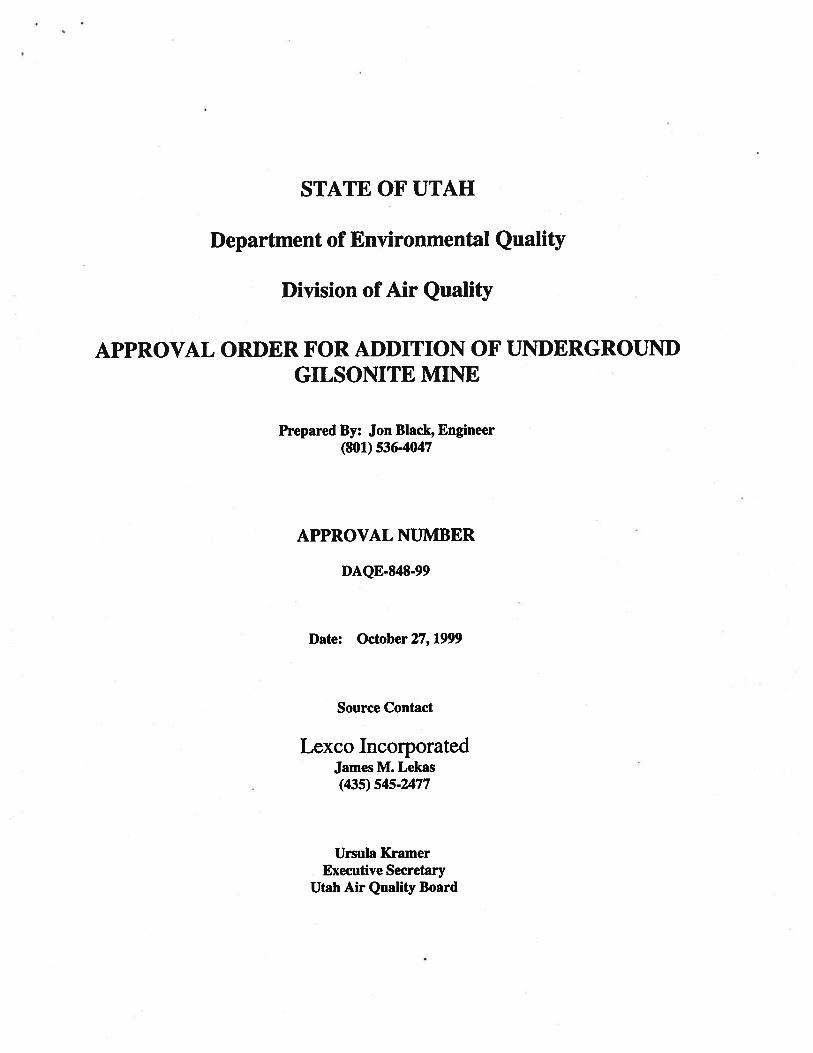
Permit Number DAQE-848-99 (State of Utah Approval Order) Note: Lexco Inc. submitted Part 1 of Title V permit application as not being a major source. Letter from EPA agreed not a major source but would provide minor source applicability decision when rules promulgated in 2004/2005. No other correspondence has been found to date. Date of the Permit Action October 27, 1999 (See Attachment B.1)
Facility Name on the Permit
Permit Number (xx-xxx-xxxxx-xxxx.xx)
Date of the Permit Action
Facility Name on the Permit
Permit Number (xx-xxx-xxxxx-xxxx.xx)
Date of the Permit Action
Facility Name on the Permit
Page 3 of 7
Permit Number (xx-xxx-xxxxx-xxxx.xx)
Date of the Permit Action
Facility Name on the Permit
Permit Number (xx-xxx-xxxxx-xxxx.xx)
Date of the Permit Action
C. CONTACT INFORMATION
Company Contact (Who is the primary contact for the company that owns this facility?) Nicholas J. Lott
Title Chief Operating Officer
Mailing Address 29950 S. Bonanza Hwy., Bonanza, Utah 84008 Email Address [email protected]
Telephone Number (435) 790-1930
Facsimile Number
Operator Contact (Is the company that operates this facility different than the company that owns this facility? Who is the primary contact for the company that operates this facility?) Nicholas J. Lott
Title Chief Operating Officer
Mailing Address 29950 S. Bonanza Hwy., Bonanza, Utah 84008
Email Address [email protected]
Telephone Number (435) 790-1930
Facsimile Number
Permitting Contact (Who is the person primarily responsible for Clean Air Act permitting for the company? We are seeking one main contact for the company. Please do not list consultants.) Michael Wilhite
Title Health, Safety, & Environmental Manager
Mailing Address 29950 S. Bonanza Hwy., Bonanza, Utah 84008
Email Address [email protected]
Page 4 of 7
Telephone Number (435) 781-4541
Facsimile Number
Compliance Contact (Is the person responsible for Clean Air Act compliance for this company different than the person responsible for Clean Air Act permitting? Who is the person primarily responsible for Clean Air Act compliance for the company? We are seeking one main contact for the company. Please do not list consultants.) Michael Wilhite
Title Health, Safety, & Environmental Manager
Mailing Address 29950 S. Bonanza Hwy., Bonanza, Utah 84008
Email Address [email protected]
Telephone Number (435) 781-4541
Facsimile Number
D. ATTACHMENTS
Include all of the following information (see the attached instructions) *Please do not send Part 71 Operating Permit Application Forms in lieu of the check list below. ϒ FORM SYNMIN - New Source Review Synthetic Minor Limit Request Form, if synthetic minor limits are being requested. ϒ Narrative description of the proposed production processes. This description should follow the flow of the process flow diagram to be submitted with this application. ϒ Process flow chart identifying all proposed processing, combustion, handling, storage, and emission control equipment. ϒ A list and descriptions of all proposed emission units and air pollution-generating activities. ϒ Type and quantity of fuels, including sulfur content of fuels, proposed to be used on a daily, annual and maximum hourly basis. ϒ Type and quantity of raw materials used or final product produced proposed to be used on a daily, annual and maximum hourly basis. ϒ Proposed operating schedule, including number of hours per day, number of days per week and number of weeks per year. ϒ A list and description of all proposed emission controls, control efficiencies, emission limits, and monitoring for each emission unit and air pollution generating activity. ϒ Criteria Pollutant Emissions - Estimates of Current Actual Emissions, Current Allowable Emissions, Post-Change Uncontrolled Emissions, and Post-Change Allowable Emissions for the following air pollutants: particulate matter, PM10, PM2.5, sulfur oxides (SOx), nitrogen oxides (NOx), carbon monoxide (CO), volatile organic compound (VOC), lead (Pb) and lead compounds, fluorides (gaseous and particulate), sulfuric acid mist (H2SO4), hydrogen sulfide (H2S), total reduced sulfur (TRS) and reduced sulfur compounds, including all calculations for the estimates.

Page 5 of 7
These estimates are to be made for each emission unit, emission generating activity, and the project/source in total. Note, there are no insignificant emission units or activities in this permitting program, only exempted units and activities. Please see the regulation for a list of exempted units and activities. ϒ Air Quality Review ϒ ESA (Endangered Species Act) ϒ NHPA (National Historic Preservation Act)
E. TABLE OF ESTIMATED EMISSIONS The following tables provide the total emissions in tons/year for all pollutants from the calculations required in Section D of this form, as appropriate for the use specified at the top of the form. E(i) – Proposed New Source
Pollutant Potential Emissions (tpy)
Proposed Allowable Emissions
(tpy)
PM - Particulate Matter PM10 - Particulate Matter less than 10 microns in size PM2.5 - Particulate Matter less than 2.5 microns in size SO2 - Sulfur Dioxide NOx - Nitrogen Oxides CO - Carbon Monoxide VOC - Volatile Organic Compound Pb - Lead and lead compounds Fluorides - Gaseous and particulates H2SO4 - Sulfuric Acid Mist H2S - Hydrogen Sulfide TRS - Total Reduced Sulfur RSC - Reduced Sulfur Compounds
PM PM10 PM 2.5 SO2
NOx CO
VOC Pb
Fluorides H2SO4
H2S TRS RSC
Emissions calculations must include fugitive emissions if the source is one the following listed sources, pursuant to CAA Section 302(j): (a) Coal cleaning plants (with thermal dryers); (b) Kraft pulp mills; (c) Portland cement plants; (d) Primary zinc smelters; (e) Iron and steel mills; (f) Primary aluminum ore reduction plants; (g) Primary copper smelters; (h) Municipal incinerators capable of charging more than
250 tons of refuse per day; (i) Hydrofluoric, sulfuric, or nitric acid plants; (j) Petroleum refineries; (k) Lime plants;
(l) Phosphate rock processing plants; (m) Coke oven batteries; (n) Sulfur recovery plants; (o) Carbon black plants (furnace process); (p) Primary lead smelters; (q) Fuel conversion plants; (r) Sintering plants; (s) Secondary metal production plants; (t) Chemical process plants (u) Fossil-fuel boilers (or combination thereof) totaling
more than 250 million British thermal units per hour heat input;

Page 6 of 7
(v) Petroleum storage and transfer units with a total storage capacity exceeding 300,000 barrels;
(w) Taconite ore processing plants; (x) Glass fiber processing plants; (y) Charcoal production plants;
(z) Fossil fuel-fired steam electric plants of more that 250 million British thermal units per hour heat input, and
(aa) Any other stationary source category which, as of August 7, 1980, is being regulated under section 111 or 112 of the Act.
E(ii) – Proposed New Construction at an Existing Source or Modification of an Existing Source
Pollutant Current Actual
Emissions (tpy)
Current Allowable Emissions
(tpy)
Post-Change Potential Emissions
(tpy)
Post-Change Allowable Emissions
(tpy) PM 6.16 21.33 46.74 27.51
PM10 3.29 16.11 27.41 15.04 PM 2.5 2.45 14.74 22.53 11.75 SO2
0.02 0.11 0.20 0.12
NOx 24.41 147.62 64.69 34.01 CO 8.37 52.43 96.13 54.93
VOC 1.01 6.31 7.08 3.95 Pb NA NA NA NA
Fluorides NA NA NA NA H2SO4 NA NA NA NA
H2S NA NA NA NA TRS NA NA NA NA RSC NA NA NA NA
Current Actual emissions assume CW-3 operated 1,308 hours and CW-6 operated 1,527 hours per year in 2019. Current Allowable emissions for CW-3 and CW-6 in 2019 are calculated using 8,760 hours per year. Post-Change Potential Emissions calculated using 8,760 hours per year for all engines. Post-Change Allowable Emissions assume primary engines operate 4,524 hours per year (87 hours/week) and mine dewatering engine operates 8,760 hours per year. PM - Particulate Matter PM10 - Particulate Matter less than 10 microns in size PM2.5 - Particulate Matter less than 2.5 microns in size SO2 – Sulfur Dioxide NOx - Nitrogen Oxides CO - Carbon Monoxide VOC - Volatile Organic Compound Pb - Lead and lead compounds Fluorides - Gaseous and particulates H2SO4 - Sulfuric Acid Mist H2S - Hydrogen Sulfide TRS - Total Reduced Sulfur RSC - Reduced Sulfur Compounds
[Disclaimers] The public reporting and recordkeeping burden for this collection of information is estimated to average 20 hours per response, unless a modeling analysis is required. If a modeling analysis is required, the public reporting and recordkeeping burden for this collection of information is estimated to average 60 hours per

Page 7 of 7
response. Send comments on the Agency’s need for this information, the accuracy of the provided burden estimates, and any suggested methods for minimizing respondent burden, including through the use of automated collection techniques to the Director, Collection Strategies Division, U.S. Environmental Protection Agency (2822T), 1200 Pennsylvania Ave., NW, Washington, D.C. 20460. Include the OMB control number in any correspondence. Do not send the completed form to this address.


Attachment B.1 – Utah Approval Order for Addition of Underground Gilsonite Mining Operation Approval Number DAQE-848-99


Minor New Source Application for New Construction Attachment D
Page 1 of 16
American Gilsonite Company Minor New Source Application for New Construction
D: Attachments Attachment D.1: No synthetic minor limits are being requested.
Attachment D.2: Narrative Description American Gilsonite Company (AGC) operates and mines Gilsonite® uintaite (Gilsonite) from the Cottonwood Mine in Uintah County, Utah. The mine is located on the Uintah and Ouray Indian Reservation near Bonanza, Utah. The world’s largest deposits of Gilsonite are located in this area, making it the most economical to mine with the largest quantities of material. AGC has been mining Gilsonite in the area since 1904 but did not purchase the Cottonwood Mine until 2009. Gilsonite is used as an additive for cementing and drilling fluids in the oil and gas industry and improves performance and quality in asphalt, inks, paints, stains, construction materials, and foundry castings. The Gilsonite is mined by underground methods in two phases: (1) development of a main shaft and (2) driving drifts on strike along the Gilsonite vein on either side of the main shaft. Shafts are developed by a combination of drilling the shaft with a large diameter (Teton) drill and hand sinking. The Teton drill uses a large 7-foot diameter bit to drill to a depth of generally 200 to 500 feet where the Gilsonite vein is wide enough for sinking by hand. The shaft is extended to total depth by manually mining a 26-foot cut along the vein. The shaft-support equipment is installed in conjunction with hand sinking. Each shaft consists of four compartments: two outside compartments for pipes for compressed air and the air lift; one ladderway compartment for an escapeway; and one central compartment with a mine skip for transporting miners. Once the shaft is sunk to the proposed bottom of the mine, a drift is extended on either side of the shaft about 500 to 700 feet in the vein to provide escapeways for the initial phase of mining. An escapeway shaft is then drilled and manually sunk from the ground surface down to the escapeway. Shaft sinking resumes after Gilsonite mining stops in the intermediate level. Gilsonite slope mining begins by developing two drifts, each drift being 200 vertical feet apart from the main shaft to the escapeway shaft. Development occurs on either side of the main shaft. When these drifts are completed, a 45° slope is driven downward from the floor of the upper drift. The slope is extended along the upper drift until the bottom of the slope intersects the lower drift. Mining then progresses from the bottom of the slope to the top of the slope. A pneumatic chipping hammer is used to cut the Gilsonite, which then slides down the 45°slope. The benches are mined sequentially until the escape shaft is reached. The remaining triangle of ore is mined from the top down to the bottom of the slope.

Minor New Source Application for New Construction Attachment D
Page 2 of 16
The Gilsonite ore is mined with pneumatic hammers equipped with a 12-inch long hardened steel moil. Compressed air for the chipping hammers comes from a 150-horsepower air compressor on the surface via a 3-inch-diameter steel pipe down the shaft to the working face (Jackson, 1985) (Boden & Tripp 2012). Manual labor is used underground to reduce contamination of the ore by the surrounding rock. Miners use air-driven chipping hammers to break the Gilsonite, working upward on a 45° angle. Broken ore falls by gravity to the bottom of a slope where it is pulled by vacuum into a vent pipe for transport to the surface. Roof support consists of mine timbers placed on 5-foot. centers. Mine timbers are either set in hitches and wedged into place or set on cap blocks and wedged into place. The figure below (Figure 10 from Tripp and White) illustrates the Gilsonite underground mining methods. Note there is no overhead electrical power available at the Cottonwood Mine.
Source: Boden & Tripp 20121
1 Taylor Boden and Bryce T. Tripp, 2012 (Boden & Tripp 2012). Gilsonite Veins of the Uinta Basin, Utah Special Study 141 Utah Geological Survey a Division of Utah Department of Natural Resources.

Minor New Source Application for New Construction Attachment D
Page 3 of 16
As active mine work progresses below the water table, the mine is dewatered by 50-horsepower submersible pumps. AGC conveys the mined ore from the shaft, drift, or slope by means of an air lift system. The air lift also has three additional functions: (1) ventilates the mine; (2) breaks the ore into smaller pieces as it is transported; and (3) removes the small quantity of water that permeates the mine. The Cottonwood Mine airlift system consists of a single Roots positive displacement blower, a Mac Filter baghouse (baghouse), ore bin with truck loading sock and piping. Each mine or shaft has two air lift systems. Each blower is driven by a 100-horsepower electric motor that develops approximately 7,700 cubic feet per minute of air volume to pneumatically convey the Gilsonite to the surface. Gilsonite ore is then pulled into a baghouse by the vacuum system through a filter fabric sock before being dropped into the ore bin through a rotary airlock. Photograph 1 shows a picture of the bins and baghouse.
Photograph 1: Ore bins with baghouses adjacent to headframe
Covered trucks use a loading sock that extends into the truck (See Photograph 2).

Minor New Source Application for New Construction Attachment D
Page 4 of 16
Photograph 2: Covered haul truck being loaded with Gilsonite at CW-3
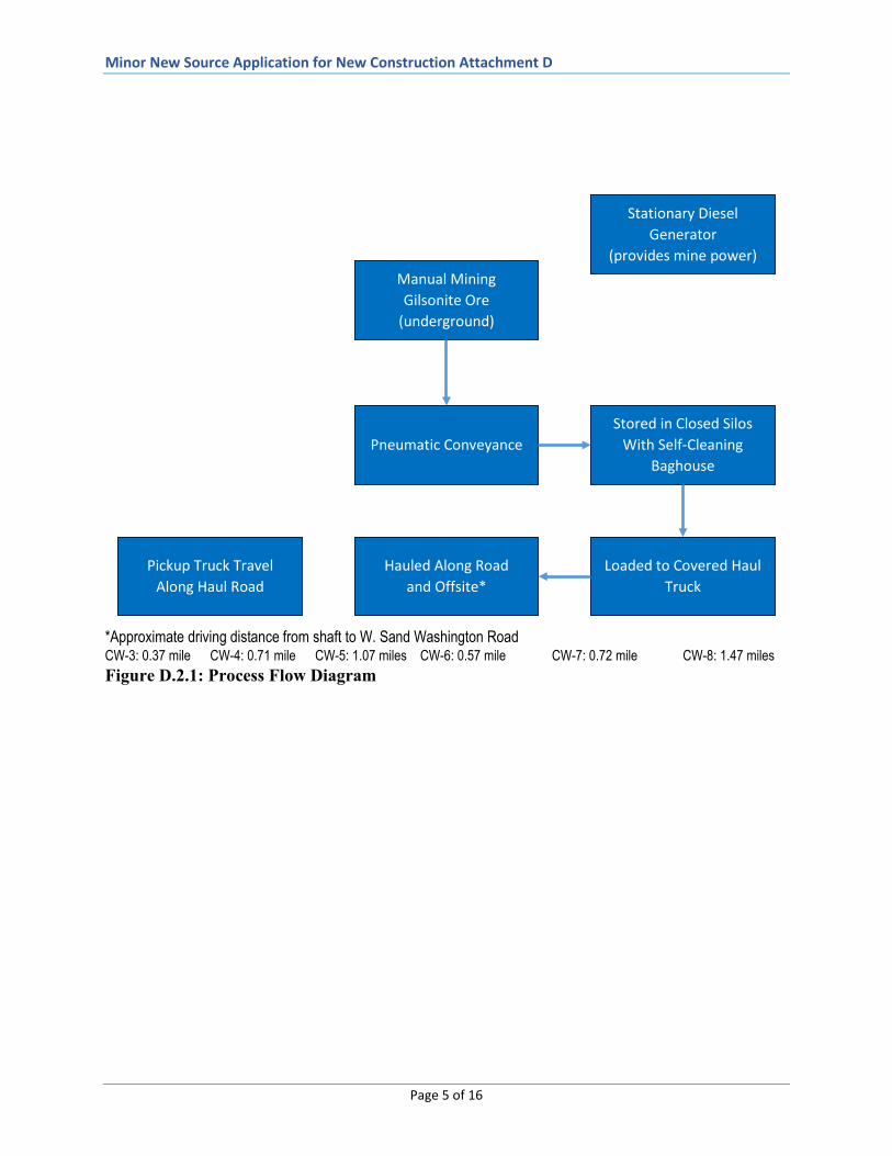
The Gilsonite ore is hauled from the Cottonwood Mine to the Bonanza operations area in a covered truck. Based on the proposed production and operating schedules in the Cottonwood mine plan, eight truck round trips per day are required to haul the projected tonnage. Seven vehicle round trips are projected per day for the mining crews and surface personnel for three mines operating. The site roads are constructed of native materials and gravel. The length of the site road from W Sand Washington Road to the Cottonwood mines ranges from 0.37 mile for CW-3 to 0.72 mile for CW-7 (See Figure D.2.1). Vehicular dust on the unpaved road will be minimized by maintaining 5 mph speed limits on all on lease access roads. Roads will be watered as necessary to control dust. No electric transmission lines are available in the area, so all power comes from diesel engines to operate any equipment. Currently two diesel engines, CW-6 (non-tiered) and CW-3 (Tier 2), provide mine power. Figure D.2.1 shows the process flow diagram described in this section. Figure D.2.2 shows an isometric view of the mine workings and surface facilities to illustrate the process flow diagram.
Minor New Source Application for New Construction Attachment D
Page 5 of 16
*Approximate driving distance from shaft to W. Sand Washington Road CW-3: 0.37 mile CW-4: 0.71 mile CW-5: 1.07 miles CW-6: 0.57 mile CW-7: 0.72 mile CW-8: 1.47 miles Figure D.2.1: Process Flow Diagram
Stationary Diesel Generator
(provides mine power)
Stored in Closed Silos With Self-Cleaning
Baghouse Pneumatic Conveyance
Manual Mining Gilsonite Ore
(underground)
Loaded to Covered Haul Truck
Hauled Along Road and Offsite*
Pickup Truck Travel Along Haul Road

Minor New Source Application for New Construction Attachment D
Page 6 of 16
Figure D.2.2: Isometric View of Gilsonite Workings and Surface Facilities
Cottonwood Mine Plan A 5-year mining plan was developed for AGC’s Utah operations based on market demand and customer specifications. Mining from Gilsonite veins is scheduled based on each Gilsonite vein’s properties as well as compliance with customer demands and may vary from year to year. Depending on market demand and ore properties, mine life, (i.e. shaft with primary engine) varies from 5 to 10 years. Mine sites may become inactive for periods of a few months up to three years until that grade of Gilsonite is required by customers. During these temporary idle periods, mine infrastructure remains on site. Presently, CW-3 and CW-6 are currently used to generate power at the Cottonwood Mines. The annual operating hours and tons produced from 2015 to 2019 are shown in Table D.2.1. Table D.2.1: Cottonwood Mine Annual Operating Hours and Tons Produced 2015-2019

Minor New Source Application for New Construction Attachment D
Page 7 of 16
The projected annual production of Gilsonite for 2020 through 2025 ranges from 5,500 to 20,000 tons depending on market demand. Table D.2.2 shows the proposed production schedule.
Table D.2.2: Proposed Production Schedule
Year
Annual Operating
Days*
Production Hours per
Day**
Tons per Day
Total Annual Tons***
Number of Mines
Annual Tons per
Mine
Maximum Hourly
Tons per Mine
2020 208 20 26.44 5,500 2 2,750 0.66 2021 208 20 76.92 16,000 3 5,333 1.28 2022 208 20 96.15 20,000 3 6,667 1.60 2023 208 20 96.15 20,000 3 6,667 1.60 2024 208 20 96.15 20,000 3 6,667 1.60 2025 208 20 96.15 20,000 3 6,667 1.60
*Based on 4 days per week, 52 weeks per year for mining**Based on 2-10-hour shifts per day***Total annual tonnage based on Cottonwood Mine plan
Table D.2.3 shows the proposed operating schedule.
Table D.2.3: Proposed Operating Schedule
Unit No. Rating
Hours per Day
Days per
Week*
Weeks per
Year
Total Annual Hours Comments
CW-3 Tier 2 20 4.35 52 4,524 Existing
CW-6 Tier 4 20 4.35 52 4,524 New engine that replaces existing non-tier engine
CW-7 Tier 4 20 4.35 52 4,524 New engine for new mine TBD Tier 4 24 7 52 8,760 Mine dewatering engine
*Based on 80 hours per week for mining and 7 hours per week for mine maintenance
AGC anticipates commencing shaft sinking for CW-7 in 2021. Three primary engines will be required when CW-7 starts shaft sinking. CW-7 is located on the southeastern end of the lease boundary. As mining is completed at CW-6, shaft sinking will begin at CW-8. CW-8 is located approximately 4,800 feet northwest of the CW-1 shaft (See Figure D.2.3). From CW-8, mining then progresses southeast toward CW-5 to CW-4 and CW-2 depending on mining conditions. Mining will then progress from CW-8 to the northwest.

Minor New Source Application for New Construction Attachment D
Page 8 of 16
Figure D.2.3: Cottonwood Mine Site and Lease Area

Minor New Source Application for New Construction Attachment D
Page 9 of 16
Attachment D.3: Emissions Units and Controls The emission sources from the mine are combustion emissions from the mine power generators, particulate emissions from handling of the Gilsonite, and particulate emissions from the vehicle traffic on mine roads. AGC has removed the CW-1 (non-tiered) engine from the Cottonwood Mine site and has ordered a new Tier 4 engine to replace CW-6 (a non-tiered) engine in accordance with the compliance plan. The anticipated delivery date is April 2020. A second Tier 4 engine will be ordered for delivery in 2021 to be used for CW-7. The order date for the 400 kW diesel generator for mine dewatering is also anticipated to be 2021.
AGC is proposing to utilize three primary engines to provide mine power for the Gilsonite mining operations. A fourth engine will provide electric power to mine dewatering pump(s). Table D.3.1 defines the proposed generators to be installed at AGC.
Table D.3.1: Proposed Emissions Units
Unit ID Engine Make
Engine Model
Serial Number
Rated Horsepower
Date of Manufacture
Emissions Certification
CW-3 Cummins QSK23-G7 NR2 00316414 1,220 04/2007 Tier 2
CW-6* Cummins TBD TBD 1,080 TBD Tier 4 CW-7 Cummins TBD TBD 1,080 TBD Tier 4 Mine
Dewatering Cummins TBD TBD 536 TBD Tier 4
* The new Tier 4 engine replaces the existing CW-6 non-tier engine.
Because all engines are subject to 40 CFR 60 Subpart IIII - New Source Performance Standards for Stationary Compression Ignition Internal Combustion Engines, all four engines will consume ultra-low sulfur diesel (ULSD). Table D.3.2 lists the fuel usage for each type of engine.
Table D.3.2: Fuel Usage by Engine
Engine Type Gal/hr. (max) Gal/day Gal/yr CW-3/Tier 2 55.2 1,104 249,725 Prime/Tier 4 63.9 1,278 289,084 Mine Dewatering/Tier 4 32.4 778 283,824
The Tier 4 engines will each be equipped with both a selective catalytic reduction (SCR) and diesel particular filter (DPF). CW-3 (Tier 2) has adjustments to reduce NOx emissions and uses ULSD fuel (see Attachment D.4.1 Critical Emission Estimates for Cottonwood Mine Engine CW-3). See Attachments D.3.1and D.3.2 for the manufacturer’s engine specifications for the primary Tier 4 and mine dewatering engines respectively.
The fugitive sources have the following controls:
1. The haul roads will be sprayed with water, as necessary. 2. An enclosed air lift system conveys the Gilsonite ore from the underground working faces
through a pipe into a baghouse on top of the storage silo. Gilsonite transfers from the

Minor New Source Application for New Construction Attachment D
Page 10 of 16
baghouse through a rotary airlock into the storage silo. Covered trucks are loaded with Gilsonite through a loading sock that drops into the truck.
3. When properly used and maintained, the baghouse fabric socks have a 99.99% or better mass efficiency rating on incoming dust-laden gas stream (based on 2 micron or larger dust particles). Emissions from the needled felt polyester filter fabric will not exceed an average of 0.02 grain per dry standard cubic foot of air exhausted from the fans based on manufacturer’s data information from 1999 (See Attachment D.3.3).
4. Per Mine Safety Health Administration regulations, AGC visually inspects the baghouse each shift for any signs of dust emissions. If dust emissions are observed, the baghouse is taken out of service to clean and or replace the filter socks.
5. All vehicles and the diesel generators will have their emission controls properly maintained and documented by maintenance work orders.
Attachment D.4: Criteria Pollutant Emissions The emissions factors and calculations are included in Attachment D.4.1.
Attachment D.5: Air Quality Review The Cottonwood Mine is located approximately 26 miles southwest of Bonanza, Utah, and 38 miles south of Vernal, Utah. The mine is located on the Uintah and Ouray Indian Reservation. The Uinta Mountains run east to west and are north of the mine, while the Book Cliffs are south-southwest of the mine and the Wasatch Mountains are west of the mine. The mine is east-southeast of the Green River, which is approximately 10 miles away. The terrain forms the Uintah Basin, where air will stagnate and produce weather inversions particularly in the winter months. The area is a semi-arid to arid climate with relatively little precipitation or vegetation, significant sunshine, and low relative humidity. Vernal’s highest average temperature is 90 degrees Fahrenheit (°F) in July, while the lowest average temperature is 5 °F in January.2 October typically has the highest average precipitation (1.06 inches) and February usually has the lowest average precipitation (0.48 inch). Vernal has an annual average total precipitation of 8.31 inches and annual average snow fall of 15.3 inches. The terrain is filled with scrub with only a minimal change in elevation. Each shaft site has an elevation of between 5,400 to 5,500 feet. The Uintah Basin is pocketed with oil and gas wells. Other than activities associated with those wells, the population and development in the area is sparse. The mine land is leased from the Bureau of Land Management (BLM). The ambient air boundaries from each shaft vary between 183 to 632 feet. The ambient air concentrations for ozone are above the 8-hour ozone 2015 standard [0.070 part per million (ppm)] National Ambient Air Quality Standards (NAAQS); therefore, the area is
2 The Vernal, Utah average weather conditions are from the Western Regional Climate Center (wrcc.dri.edu) for the period of 1928 through 2005.

Minor New Source Application for New Construction Attachment D
Page 11 of 16
considered nonattainment for ozone, with a marginal nonattainment classification. The area is in attainment for all other NAAQS. The stack parameters associated with the engines are shown in Table D.5.1: Table D.5.1 Engine Stack Parameters
Unit HP (derated)
Tier Standard
Flow Rate
(SCFM)
Exhaust Temp (°F)
Stack Height
1(ft)
Stack Diameter1 (inches)
CW-3 1,222 (1,222) Tier 2 2,201 862 7.5 6
CW-62 1,207 (1,080) Tier 4 2,801 852 8 6
CW-7 1,207 (1,080) Tier 4 2,801 852 8 6
Mine Dewatering
536 (433) Tier 4 3.945 909 7 4
1 Values are approximate and can be defined upon source selection. 2 The new tier 4 engine replaces the existing non-tier engine in 2020. The emissions for the Cottonwood Mine are calculated for: (1) current existing and allowable emissions for the existing diesel engines (CW-3 and CW-6); and (2) the post change potential and allowable emissions for CW-3 (Tier 2), CW-6 (Tier 4), CW-7 (Tier 4) and a mine dewatering (Tier 4) diesel generators. The current existing emissions were calculated using the operating hours for 2019 shown in Table D.4.2.1. The post change proposed operating hours for each engine are shown in Table D.2.2. The actual allowable and post change potential emissions were calculated using 8,760 hours per year. The current actual emissions were calculated using the annual tons produced for 2019 as shown in Table D.4.1. The annual Gilsonite production used for the post change allowable emissions calculations is 20,000 tons. The annual production tons for the current allowable and post change potential emissions were calculated by multiplying the existing and or proposed annual production tons by the ratio of 8,760 divided by the operating hours. As an example, the annual production tons for the post change potential emissions was calculated as follows.
• Post change annual production = 20,000 • Post change proposed operating hours = 4,524 • Post change potential operating hours = 8,760
Post change annual production tons = 20,000 x 8,760/4,524 = 38,726.79 or 38,727.
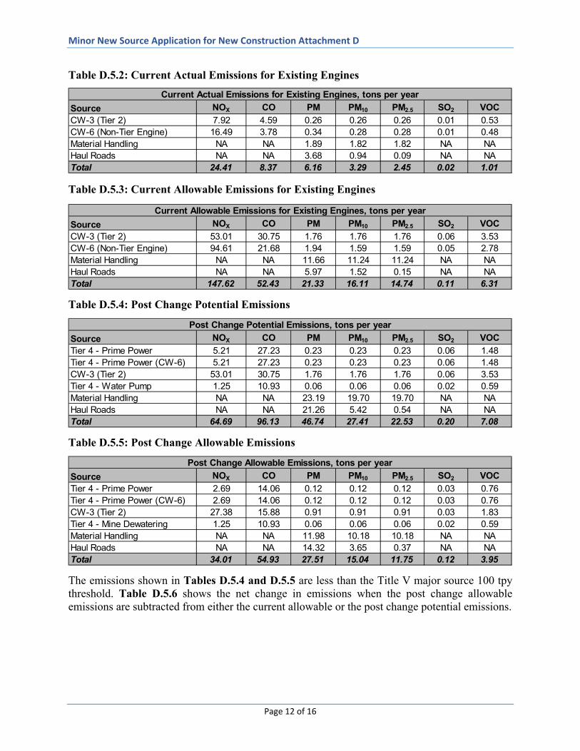
Table D.5.2 below shows the current actual emissions, while Table D.5.3 shows the current allowable emissions for CW-3 and CW-6. The post change potential and allowable emissions are shown in Tables D.5.4 and D.5.5 respectively.
Minor New Source Application for New Construction Attachment D
Page 12 of 16
Table D.5.2: Current Actual Emissions for Existing Engines
Table D.5.3: Current Allowable Emissions for Existing Engines
Table D.5.4: Post Change Potential Emissions
Table D.5.5: Post Change Allowable Emissions
The emissions shown in Tables D.5.4 and D.5.5 are less than the Title V major source 100 tpy threshold. Table D.5.6 shows the net change in emissions when the post change allowable emissions are subtracted from either the current allowable or the post change potential emissions.
Source NOX CO PM PM10 PM2.5 SO2 VOCCW-3 (Tier 2) 7.92 4.59 0.26 0.26 0.26 0.01 0.53CW-6 (Non-Tier Engine) 16.49 3.78 0.34 0.28 0.28 0.01 0.48Material Handling NA NA 1.89 1.82 1.82 NA NAHaul Roads NA NA 3.68 0.94 0.09 NA NATotal 24.41 8.37 6.16 3.29 2.45 0.02 1.01
Current Actual Emissions for Existing Engines, tons per year
Source NOX CO PM PM10 PM2.5 SO2 VOCCW-3 (Tier 2) 53.01 30.75 1.76 1.76 1.76 0.06 3.53CW-6 (Non-Tier Engine) 94.61 21.68 1.94 1.59 1.59 0.05 2.78Material Handling NA NA 11.66 11.24 11.24 NA NAHaul Roads NA NA 5.97 1.52 0.15 NA NATotal 147.62 52.43 21.33 16.11 14.74 0.11 6.31
Current Allowable Emissions for Existing Engines, tons per year
Source NOX CO PM PM10 PM2.5 SO2 VOCTier 4 - Prime Power 5.21 27.23 0.23 0.23 0.23 0.06 1.48Tier 4 - Prime Power (CW-6) 5.21 27.23 0.23 0.23 0.23 0.06 1.48CW-3 (Tier 2) 53.01 30.75 1.76 1.76 1.76 0.06 3.53Tier 4 - Water Pump 1.25 10.93 0.06 0.06 0.06 0.02 0.59Material Handling NA NA 23.19 19.70 19.70 NA NAHaul Roads NA NA 21.26 5.42 0.54 NA NATotal 64.69 96.13 46.74 27.41 22.53 0.20 7.08
Post Change Potential Emissions, tons per year
Source NOX CO PM PM10 PM2.5 SO2 VOCTier 4 - Prime Power 2.69 14.06 0.12 0.12 0.12 0.03 0.76Tier 4 - Prime Power (CW-6) 2.69 14.06 0.12 0.12 0.12 0.03 0.76CW-3 (Tier 2) 27.38 15.88 0.91 0.91 0.91 0.03 1.83Tier 4 - Mine Dewatering 1.25 10.93 0.06 0.06 0.06 0.02 0.59Material Handling NA NA 11.98 10.18 10.18 NA NAHaul Roads NA NA 14.32 3.65 0.37 NA NATotal 34.01 54.93 27.51 15.04 11.75 0.12 3.95
Post Change Allowable Emissions, tons per year

Minor New Source Application for New Construction Attachment D
Page 13 of 16
Table D.5.6: Change in Emissions
Table D.5.6 shows:
1. The changes in emissions (tpy) between the current allowable and post change allowable are 1) a net decrease in NOx,(113.61), PM10 (1.07) PM2.5,(2.99) and VOC (2.37) , 2) increases in CO (2.50) and PM (6.18) and no change in SO2, and
2. All emissions for the post change allowable (tpy) are reduced from the post change potential emissions.
Contributing factors to the reductions in emissions include: (1) the removal of CW-1 (non-tiered diesel generator) from the Cottonwood Mine on December 11, 2019; (2) removal of the existing CW-6 (non-tiered diesel generator) in April 2020: (3) installation of the new Tier 4 diesel generator at CW-6 when the mine resumes operation in 2020; and (4) purchase of new Tier 4 engines for CW-7 and the mine dewatering pumps.
The increases in CO and PM occur from the increases in annual tons (20,000) and truck trips per day (8) for potential allowable emissions versus 14,200 annual tons and 5 truck trips per day for the current allowable emissions.
Emissions Status NOX CO PM PM10 PM2.5 SO2 VOCPost Change Allowable - Current Allowable -113.61 2.50 6.18 -1.07 -2.99 0.00 -2.37Post Change Allowable - Post Change Potential -30.68 -41.20 -19.23 -12.37 -10.78 -0.09 -3.14Note: Positive values are net increase in emissions. Negative values are a net reduction in emissions.
Change in Emissions, tons per year
Minor New Source Application for New Construction Attachment D
Page 14 of 16
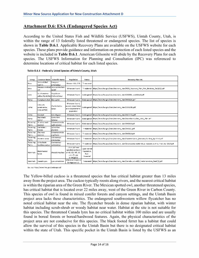
Attachment D.6: ESA (Endangered Species Act) According to the United States Fish and Wildlife Service (USFWS), Uintah County, Utah, is within the range of 13 federally listed threatened or endangered species. The list of species is shown in Table D.6.1. Applicable Recovery Plans are available on the USFWS website for each species. These plans provide guidance and information on protection of each listed species and the website is included in Table D.6.1. American Gilsonite will abide by the Recovery Plans for each species. The USFWS Information for Planning and Consultation (IPC) was referenced to determine locations of critical habitat for each listed species.
The Yellow-billed cuckoo is a threatened species that has critical habitat greater than 13 miles away from the project area. The cuckoo typically roosts along rivers, and the nearest critical habitat is within the riparian area of the Green River. The Mexican spotted owl, another threatened species, has critical habitat that is located over 22 miles away, west of the Green River in Carbon County. This species of owl is found in mixed conifer forests and canyon settings, and the Uintah Basin project area lacks these characteristics. The endangered southwestern willow flycatcher has no noted critical habitat near the site. The flycatcher breeds in dense riparian habitat, with winter habitat including scrub-shrub or woody habitat near water. Habitat at the site is not suitable for this species. The threatened Canada lynx has no critical habitat within 100 miles and are usually found in boreal forests or boreal/hardwood features. Again, the physical characteristics of the project area are not conducive for this species. The black footed ferret has a habitat that could allow the survival of this species in the Uintah Basin but there is no designated critical habitat within the state of Utah. This specific pocket in the Uintah Basin is listed by the USFWS as an

Minor New Source Application for New Construction Attachment D
Page 15 of 16
experimental population, non-essential, however it is located more than 25 miles from the project area. The ferret has a listing status of endangered and experimental population, non-essential. The listed threatened and endangered vegetation and fish species evaluated for the project area include shrubby reed-mustard, Ute ladies-tresses, clay reed-mustard, Pariette cactus, and Uinta Basin hookless cactus; as well as the humpback chub, Colorado pike minnow, bonytail chub, and razorback sucker. The nearest critical habit for a fish species is greater than 7 miles away, with no permanent waterbodies adjacent to the site. Much of the area around the site has previously been disturbed due to earlier mining activity, energy development, and livestock grazing. The Bureau of Land Management completed an environmental assessment for the area proposed for development. This document, Environmental Assessment UT-USO-09-0073, was submitted on January 29, 2009, and concluded that no special status, threatened, or endangered plant species were present at the site. Because the project area is not close in proximity to any threatened and endangered mammal species or the associated critical habitats, there will be no anticipated impacts to any of the referenced mammal species from construction and operation of the proposed source. No impacts to listed fish species are expected; permanent waterbodies and suitable habitat are not found at or adjacent to the site. No listed vegetation species were documented at the site during the 2009 Environmental Assessment. Attachment D.7: National Historic Preservation Act
That National Park Service publishes a National Register of Historic Places. All properties listed on the National Register within Uintah County, Utah, are included in Table D.7.1. The nearest listed property is more than 30 miles from the site. The Environmental Assessment indicated that no cultural resources have been identified at the site, and the project area was cleared by the Vernal archaeologist in 2008.
3 U.S. Department of Interior Bureau of Land Management,
Environmental Assessment UT-USO-09-007, Lexco #6, #7 & #8 Shafts Mining Plan Modification, Federal Gilsonite Lease UTU-72699, Location: T. 10 S., R. 21 E, Section 34, SWNE, NWNW, S2NW, N2SE; Section 35, N2SW, SESW, S2SE. T. 11 S., R. 21 E., Section 1, NENE.

Minor New Source Application for New Construction Attachment D
Page 16 of 16

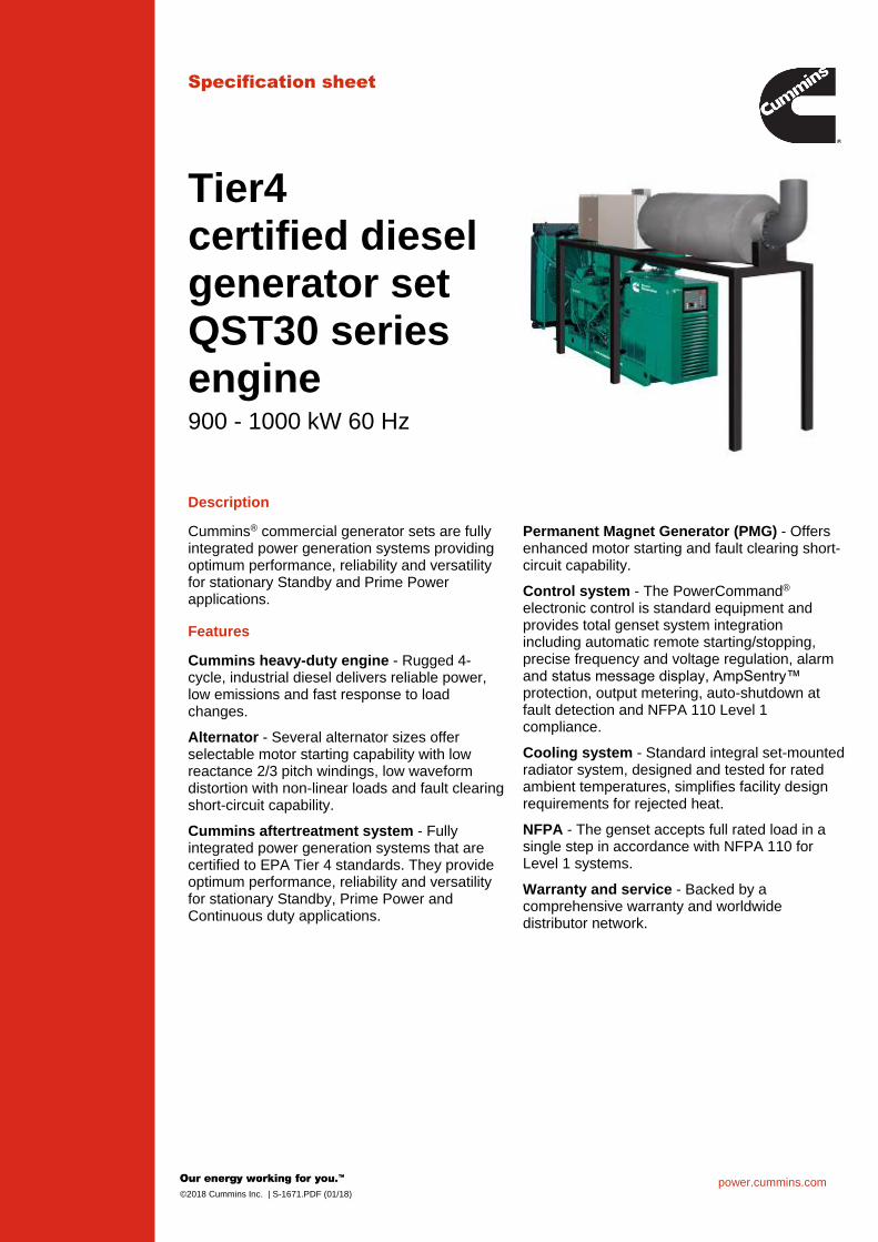
Attachment D.3.1 – Cummins 1,000 kW Diesel Generator Specifications
power.cummins.com©2018 Cummins Inc. | S-1671.PDF (01/18)
Specification sheet
Tier4certified dieselgenerator setQST30 seriesengine900 - 1000 kW 60 Hz
Description
Cummins® commercial generator sets are fullyintegrated power generation systems providingoptimum performance, reliability and versatilityfor stationary Standby and Prime Powerapplications.
Permanent Magnet Generator (PMG) - Offersenhanced motor starting and fault clearing short-circuit capability.
Control system - The PowerCommand®
electronic control is standard equipment andprovides total genset system integrationincluding automatic remote starting/stopping,precise frequency and voltage regulation, alarmand status message display, AmpSentry™ protection, output metering, auto-shutdown atfault detection and NFPA 110 Level 1compliance.
Cooling system - Standard integral set-mountedradiator system, designed and tested for ratedambient temperatures, simplifies facility designrequirements for rejected heat.
NFPA - The genset accepts full rated load in asingle step in accordance with NFPA 110 forLevel 1 systems.
Warranty and service - Backed by acomprehensive warranty and worldwidedistributor network.
Features
Cummins heavy-duty engine - Rugged 4-cycle, industrial diesel delivers reliable power,low emissions and fast response to loadchanges.
Alternator - Several alternator sizes offerselectable motor starting capability with lowreactance 2/3 pitch windings, low waveformdistortion with non-linear loads and fault clearingshort-circuit capability.
Cummins aftertreatment system - Fullyintegrated power generation systems that arecertified to EPA Tier 4 standards. They provideoptimum performance, reliability and versatilityfor stationary Standby, Prime Power andContinuous duty applications.

power.cummins.com©2018 Cummins Inc. | S-1671.PDF (01/18)
Generator set specificationsGovernor regulation class ISO8528 Part 1 Class G3Voltage regulation, no load to full load +/- 0.5%Random voltage variation +/- 0.5%Frequency regulation IsochronousRandom frequency variation +/- 0.25%Radio frequency emissions compliance IEC 61000-4-2 : Level 4 Electrostatic discharge
IEC 61000-4-3 : Level 3 Radiated susceptibility
Engine specificationsBore 140 mm (5.51 in)Stroke 165.0 mm (6.5 in)Displacement 30.5 litres (1860 in3)Configuration Cast iron, V, 12 cylinderBattery capacity 1800 amps minimum at ambient temperature of -18 °C to 0 °C
(0 °F to 32 °F)Battery charging alternator 35 ampsStarting voltage 24 volt, negative groundFuel system Direct injection: number 2 diesel fuel, fuel filter, automatic
electric fuel shutoff
Fuel filter Triple element, 10 micron filtration, spin-on fuel filters with waterseparator
Air cleaner type Dry replaceable elementLube oil filter type(s) Four spin-on, combination full flow filter and bypass filtersStandard cooling system High ambient radiator
Aftertreatment specificationsModel CA451Emissions certification Tier4F certifiedDuct diameter 1143 mm (45 in)Duct quantity 1Components included Insulated aftertreatment ducts, saddle supports for
aftertreatment, control panel, DEF tank, heater with ILB,harness from control panel to engine and AFT, lifting tool.Assembly required at site.
Alternator specificationsDesign Brushless, 4 pole, drip proof, revolving fieldStator 2/3 pitchRotor Single bearing, flexible discInsulation system Class H on low and medium voltage, Class F on high voltageStandard temperature rise 150 ºC Standby at 40 °C ambientExciter type Permanent Magnet Generator (PMG)Phase rotation A (U), B (V), C (W)Alternator cooling Direct drive centrifugal blower fanAC waveform Total Harmonic Distortion (THDV) < 5% no load to full linear load, < 3% for any single harmonicTelephone Influence Factor (TIF) < 50% per NEMA MG1-22.43Telephone Harmonic Factor (THF) < 3%

power.cummins.com©2018 Cummins Inc. | S-1671.PDF (01/18)
PowerCommand 3.3 Control System
An integrated microprocessor based generator set control systemproviding voltage regulation, engine protection, alternator protection,operator interface and isochronous governing. Refer to document S-1570 for more detailed information on the control.AmpSentry – Includes integral AmpSentry protection, whichprovides a full range of alternator protection functions that arematched to the alternator provided.Power management – Control function provides battery monitoringand testing features and smart starting control system.Advanced control methodology – Three phase sensing, full waverectified voltage regulation, with a PWM output for stable operationwith all load types.Communications interface – Control comes standard with PCCNetand Modbus interface.Regulation compliant – Prototype tested: UL, CSA and CEcompliant.Service - InPower™ PC-based service tool available for detaileddiagnostics, setup, data logging and fault simulation.Easily upgradeable – PowerCommand controls are designed withcommon control interfaces.Reliable design – The control system is designed for reliableoperation in harsh environment.Multi-language support
Operator panel featuresOperator/display functions Displays paralleling breaker status Provides direct control of the paralleling breaker 320 x 240 pixels graphic LED backlight LCD Auto, manual, start, stop, fault reset and lamp test/panel lamp
switches Alpha-numeric display with pushbuttons LED lamps indicating generator set running, remote start, not in
auto, common shutdown, common warning, manual run mode,auto mode and stop
Paralleling control functions First Start Sensor System selects first generator set to close to bus Phase Lock Loop Synchronizer with voltage matching Sync check relay Isochronous kW and kVar load sharing Load govern control for utility paralleling Extended Paralleling (baseload/peak shave) Mode Digital power transfer control, for use with a breaker pair to provide
open transition, closed transition, ramping closed transition,peaking and base load functions,
Alternator data Line-to-neutral and line-to-line AC volts 3-phase AC current Frequency kW, kvar, power factor kVA (three phase and total)
Engine data DC voltage Engine speed Lube oil pressure and temperature Coolant temperature Comprehensive FAE data (where applicable)Other data Genset model data Start attempts, starts, running hours, kW hours Load profile (operating hours at % load in 5% increments) Fault history Data logging and fault simulation (requires InPower)
Standard control functionsDigital governing Integrated digital electronic isochronous governor Temperature dynamic governingDigital voltage regulation Integrated digital electronic voltage regulator 3-phase, 4-wire line-to-line sensing Configurable torque matchingAmpSentry AC protection AmpSentry protective relay Over current and short circuit shutdown Over current warning Single and three phase fault regulation Over and under voltage shutdown Over and under frequency shutdown Overload warning with alarm contact Reverse power and reverse var shutdown Field overload shutdownEngine protection Battery voltage monitoring, protection and testing Overspeed shutdown Low oil pressure warning and shutdown High coolant temperature warning and shutdown Low coolant level warning or shutdown Low coolant temperature warning Fail to start (overcrank) shutdown Fail to crank shutdown Cranking lockout Sensor failure indication Low fuel level warning or shutdown Fuel-in-rupture-basin warning or shutdown Full authority electronic engine protectionControl functions Time delay start and cool down Real time clock for fault and event time stamping Exerciser clock and time of day start/stop Data logging Cycle cranking Load shed Configurable inputs and outputs (4) Remote emergency stopOptions Auxiliary output relays (2)

For more information contact your local Cummins distributoror visit power.cummins.com
©2018 Cummins Inc. All rights reserved. Cummins is a registered trademark of Cummins Inc. PowerCommand, AmpSentry, InPower and “Our energy working for you.” are trademarks of Cummins Inc. Other company, product, or service names may be trademarks or service marks of others. Specifications are subject to change without notice. S-1671.PDF (01/18)
Generator set weights and dimensions* Weights represent a set with standard features. See outline drawings for weights of other configurations.
ModelDim “A” mm (in.)
Dim “B” mm (in.)
Dim “C” mm (in.)
Set weight*dry kg (lbs)
Set weight*wet kg (lbs)
DQFAH 4239 (167) 2000 (79) 2353 (93) 7631 (16824) 7929 (17480)
Aftertreatment weights and dimensions* Due to multiple configurations of the CA451 model, maximum weight of the model is shown.Note: Dimension and weights are subject to change. See submittal data for exact details.
Aftertreatmentmodel number*
Gensetmodel
L (Length)mm (in.)
W (Width)mm (in.)
H (Height)mm (in.)
Weight of aftertreatmentsystem (lbs)
CA451 DQFAH 4651 (183) 1480 (58) 1260 (50) 4367
Codes and standardsCodes or standards compliance may not be available with all model configurations – consult factory for availability.
All low and medium voltage modelsare CSA certified to product class4215-01.
ISO8528 The generator set has been rated inaccordance with ISO8528.
U.S. EPAEngine certified to US EPA Nonroad40CFR1039 and Stationary(Emergency and Non-Emergency)US EPA NSPS, 60CFR Subpart IIIITier4 Emissions Standards.
This generator set is designed infacilities certified to ISO 9001 andmanufactured in facilities certified toISO 9001 or ISO 9002.
InternationalBuildingCode
The genset package is certified forseismic application in accordancewith the following InternationalBuilding Code: IBC2012.
The Aftertreatment System bears theETL ListedMark as proof of conformityto NFPA 79, UL 61010C-1, and CSA22.2 No. 61010-1-12.
The Prototype Test Support (PTS)program verifies the performanceintegrity of the generator set design.Cummins products bearing the PTSsymbol meet the prototype testrequirements of NFPA 110 for Level1 systems.
The generator set is available listed toUL 2200 for all 60 Hz low voltagemodels, Stationary Engine GeneratorAssemblies. The PowerCommandcontrol is Listed to UL 508 - CategoryNITW7 for U.S. and Canadian usage.Circuit breaker assemblies are UL 489Listed for 100% continuous operationand also UL 869A Listed ServiceEquipment.
Warning: Back feed to a utility system can cause electrocution and/or property damage. Do not connect to any building’s electrical system except through an approved device or after building main switch is open.

©2019 D-3535 PDA047J649 (06/19)
Generator Set Data Sheet
Model: DQFAH
Frequency: 60 Hz
Fuel Type: Ultra Low Sulphur Diesel (15 ppm sulphur)
kW Rating: 1000 Standby
900 Prime
Emissions level: EPA Stationary Non-Emergency Tier 4
Exhaust emission data sheet Tier 4F: EDS-1156
Exhaust emission compliance sheet Tier4F EPA-1195
Sound performance data sheet: MSP-1119
Cooling performance data sheet: MCP-217
Prototype test summary data sheet: PTS-304
Standard set-mounted radiator cooling outline: A034N275
Optional remote radiator cooling outline: A034N273
After-treatment outline drawing Tier 4F A041V017
Fuel Consumption Standby Prime
kW (kVA) kW (kVA)
Ratings 1000 (1250) 900 (1125)
Load 1/4 1/2 3/4 Full 1/4 1/2 3/4 Full
US gph 21.2 36.6 53.3 70.7 19.7 33.5 48.1 63.9
L/hr 80.4 138.6 201.9 267.6 74.5 127.0 182.1 241.9
DEF Consumption Standby Prime
kW (kVA) kW (kVA)
Ratings 1000 (1250) 900 (1125)
Load 1/4 1/2 3/4 Full 1/4 1/2 3/4 Full
US gph 0.94 1.41 2.17 3.03 0.86 1.32 1.94 2.68
L/hr 3.55 5.34 8.21 11.47 3.26 5.00 7.34 10.14
Engine Standby rating Prime rating
Engine manufacturer Cummins Inc.
Engine model QST30-G17
Configuration Cast iron, V 12 cylinder
Aspiration Turbocharged and low temperature after-cooled
Gross engine power output, kWm (bhp) 1112 (1490) 1007 (1350)
BMEP at set rated load, kPa (psi) 2427 (351) 2199 (319)
Bore, mm (in.) 140 (5.51)
Stroke, mm (in.) 165 (6.5)
Rated speed, rpm 1800
Piston speed, m/s (ft/min) 9.91 (1950)
Compression ratio 14.7:1

For more information contact your local Cummins distributor or visit power.cummins.com
©2019 Cummins Inc. All rights reserved. Cummins is a registered trademark of Cummins Inc. PowerCommand, AmpSentry, InPower and “Our energy working for you.” are trademarks of Cummins Inc. Other company, product, or service names may be trademarks or service marks of others. Specifications are subject to change without notice. D-3535 PDA047J649 (06/19)
Lube oil capacity, L (qt) 132 (140)
Overspeed limit, rpm 2070
Regenerative power, kW 82
Fuel Flow Maximum supply fuel flow, L/hr (US gph) 570 (150)
Maximum return fuel flow, L/hr (US gph) 550 (145)
Maximum fuel inlet restriction with clean filter, kPa (in Hg) 13.5 (4.0)
Maximum fuel inlet temperature, °C (°F) 71 (160)
Maximum fuel inlet restriction, kPa (in Hg) 68 (20)
Air Combustion air, m3/min (scfm) 87 (3067) 79 (2801)
Maximum air cleaner restriction with clean filter, kPa (in H2O)
3.7 (15)
Alternator cooling air, m3/min (cfm) 204 (7300)
Exhaust Exhaust flow at rated load, m3/min (cfm) 212 (7469) 193 (6829)
Exhaust temperature, °C (°F) 465 (869) 456 (852)
Maximum back pressure, kPa (in H2O) 6.8 (27)
Standard Set-Mounted Radiator Cooling Ambient design at 0.5 in H2O, °C (°F) 50 (122)
Fan load, kWm (HP) 33.1 (44.4)
Coolant capacity (with radiator), L (US gal) 167 (44)
Cooling system air flow, m3/min (scfm) 1097.5 (38753)
Total heat rejection, MJ/min (Btu/min) 48.9 (46455)
Maximum cooling air flow static restriction, kPa (in H2O) 0.12 (0.5)
Maximum fuel return line restriction kPa (in Hg) 67.5 (20)

©2019 D-3535 PDA047J649 (06/19)
Maximum fuel return line restriction, kPa (in Hg) 67.5 (20)
1 For non-standard remote installations contact your local Cummins representative.
Aftertreatment System T4F
Pressure drop across after-treatment, kPa (in H2O) 6.2 (25)
Available back pressure for exhaust system piping, kPa (in H2O) 0.5 (2)
Exhaust heater rating (kW) 250
Exhaust heater input requirements (Amps at 480 V) 300
DEF tank capacity (usable) L (gal) 765 (202)
Heat radiated from aftertreatment, Btu/min (MJ/min) 1820 (1.92)
DEF Flow Maximum supply flow, L/hr (US gph) 98 (26)
Maximum return flow, L/hr (US gph) 87 (23)
Maximum static head (from pump to injector), m (ft) 6.4 (21)
Weights1 Unit dry weight kgs (lbs) 7633 (16824)
Unit wet weight kgs (lbs) 7931 (17480)
Aftertreatment weight kgs (lbs) 1981 (4367)
Derating Factors2
Standby Engine power available up to 701 m (2300 ft) at ambient temperatures up to 40 °C (104 °F). Above these elevations, derate at 3.5% per 305 m (1000 ft) and 7% per 10 °C (18 °F).
Prime Engine power available up to 727 m (2385 ft) at ambient temperatures up to 40 °C (104 °F). Above these elevations, derate at 3.5% per 305 m (1000 ft) and 7% per 10 °C (18 °F).
Notes: 1 Weights represent a set with standard features. See outline drawing for weights of other configurations. 2 Derating factors do not include after-treatment system.
Ratings Definitions Emergency Standby Power (ESP):
Limited-Time Running Power (LTP):
Prime Power (PRP): Base Load (Continuous) Power (COP):
Applicable for supplying power to varying electrical load for the duration of power interruption of a reliable utility source. Emergency Standby Power (ESP) is in accordance with ISO 8528. Fuel Stop power in accordance with ISO 3046, AS 2789, DIN 6271 and BS 5514.
Applicable for supplying power to a constant electrical load for limited hours. Limited-Time Running Power (LTP) is in accordance with ISO 8528.
Applicable for supplying power to varying electrical load for unlimited hours. Prime Power (PRP) is in accordance with ISO 8528. Ten percent overload capability is available in accordance with ISO 3046, AS 2789, DIN 6271 and BS 5514.
Applicable for supplying power continuously to a constant electrical load for unlimited hours. Continuous Power (COP) is in accordance with ISO 8528, ISO 3046, AS 2789, DIN 6271 and BS 5514.
Alternator Data
Voltage Connection1 Temp rise degrees C
Duty2 Single phase factor3
Max surge kVA4
Surge kW
Alternator data sheet
Feature code
120/208-139/240 12-lead 125/105 S/P 4234 1019 ADS-312 B252

For more information contact your local Cummins distributor or visit power.cummins.com
©2019 Cummins Inc. All rights reserved. Cummins is a registered trademark of Cummins Inc. PowerCommand, AmpSentry, InPower and “Our energy working for you.” are trademarks of Cummins Inc. Other company, product, or service names may be trademarks or service marks of others. Specifications are subject to change without notice. D-3535 PDA047J649 (06/19)
240/416-277/480 12-lead 125/105 S/P 4234 1019 ADS-312 B252
277/480 Wye, 3-phase 125/105 S/P 3866 1018 ADS-311 B276
220/380-277/480 Wye, 3-phase 125/105 S/P 4602 1018 ADS-330 B282
220/380-277/480 Wye, 3-phase 105/80 S/P 4602 1018 ADS-330 B283
210/380-277/480 Wye, 3-phase 80 S 5521 1024 ADS-331 B284
240/416-277/480 Wye 125/105 S/P 4234 1019 ADS-312 B288
347/600 3-phase 125/105 S/P 3866 1021 ADS-311 B300
347/600 3-phase 105/80 S/P 4234 1024 ADS-312 B301
347/600 3-phase 80 S 4602 1004 ADS-330 B604
Notes: 1 Limited single phase capability is available from some three phase rated configurations. To obtain single phase rating,
multiply the three phase kW rating by the Single Phase Factor3. All single phase ratings are at unity power factor. 2 Standby (S), Prime (P) and Continuous ratings (C). 3 Factor for the Single phase output from Three phase alternator formula listed below. 4 Maximum rated starting kVA that results in a minimum of 90% of rated sustained voltage during starting.
Formulas for calculating full load currents:
Three phase output Single phase output
kW x 1000 kW x SinglePhaseFactor x 1000
Voltage x 1.73 x 0.8 Voltage
Warning: Back feed to a utility system can cause electrocution and/or property damage. Do not connect to any building’s electrical system except through an approved device or after building main switch is open.

Cummins Inc. Data and specification subject to change without notice ADS-312 (09/17)
Alternator data sheet Frame size: HC6K
Characteristics Weights: Wound stator assembly: 2553 lb 1150 kg Rotor assembly: 2426 lb 1093 kg Complete alternator: 5162 lb 2325 kg Maximum speed: 2250 rpm Excitation current: Full load: 2.5 Amps No load: 0.5 Amps Insulation system: Class H throughout
3 ∅ Ratings (0.8 power factor) 60 Hz 50 Hz (Based on specific temperature rise at 40° C ambient temperature)
110/190* 220/380
120/208* 240/416
139/240* (277/480)
347/600
110/190* 220/380
120/208* 240/415
127/220* 254/440
150° C rise ratings kW 985 1080 1220 1220 944 944 944 kVA 1231 1350 1525 1525 1180 1180 1180 125° C rise ratings kW 930 1020 1150 1150 888 888 888 kVA 1163 1275 1438 1438 1110 1110 1110 105° C rise ratings kW 865 950 1050 1050 800 800 800 kVA 1081 1188 1313 1313 1000 1000 1000 80° C rise ratings kW 750 824 900 900 708 708 708 kVA 938 1030 1125 1125 885 885 885
Reactances (per unit ± 10%) 110/190* 220/380
120/208* 240/416
139/240* 277/480
347/600
110/190* 220/380
120/208* 240/415
127/220* 254/440
(Based on full load at 125° C rise rating) Synchronous 3.45 3.15 2.67 2.67 2.77 2.32 2.07 Transient 0.27 0.25 0.21 0.21 0.23 0.20 0.17 Subtransient 0.19 0.18 0.15 0.15 0.17 0.14 0.13 Negative sequence 0.26 0.24 0.20 0.20 0.22 0.18 0.16 Zero sequence 0.03 0.03 0.02 0.02 0.03 0.02 0.02
Motor starting Broad range 600 Broad range
Maximum kVA (90% sustained voltage) 4234 4234 2875
Time constants (sec)
Broad range 600 Broad range
Transient 0.185 0.185 0.185 Subtransient 0.025 0.025 0.025 Open circuit 3.400 3.400 3.400 DC 0.049 0.049 0.049
Windings (@ 20° C) Broad range 600 Broad range
Stator resistance (Ohms per phase) 0.0038 0.0052 0.0038 Rotor resistance (Ohms) 1.8900 1.8900 1.8900 Number of leads 6 (12 Optional) 6 6 (12 optional)
* 12 lead reconnectible option is required to obtain low (parallel wye) voltages.

Cummins Inc. Data and specification subject to change without notice PTS-304 (09/17)
Prototype Test Support (PTS) 60 Hz test summary
Generator set models Representative prototype
750DQFAE 1000DQFAH Model: 1000DQFAD
800DQFAF Engine: P734C
900DQFAG Alternator: QST30-G5 NR2
The following summarizes prototype testing conducted on the designated representative prototype of the specified models. This testing is conducted to verify the complete generator set electrical and mechanical design integrity. Prototype testing is conducted only on generator sets not sold as new equipment.
Maximum surge power: 1055 kW The generator set was evaluated to determine the stated maximum surge power. Maximum motor starting: 5521 kVA The generator set was tested to simulate motor starting by applying the specified kVA load at low lagging power factor (0.4 or lower). With this load applied, the generator set recovered to a minimum of 90% rated voltage. Torsional analysis and testing: The generator set on P7G was tested to verify that the design is not subjected to harmful torsional stresses. A spectrum analysis of the transducer output was conducted over the speed range of 1200 to 2000 RPM. Cooling system: 50 °C ambient 0.5 in H2O restriction The cooling system was tested to determine ambient temperature and static restriction capabilities. The test was performed at full rated load elevated ambient temperature under static restriction conditions. Durability: The generator set was subjected to endurance test replicating field duty cycles operating at variable load up to the standby rating based upon MIL-STD-705 to verify structural soundness and durability of the design. Electrical and mechanical strength: The generator set was tested to several single phase and three phase faults to verify that the generator can safely withstand the forces associated with short circuit conditions. The generator set was capable of producing full rated output at the conclusion of the testing.
Steady state performance: The generator set was tested to verify steady state operating performance. It was within the specified maximum limits. Voltage regulation: ± 0.5% Random voltage variation: ± 0.5% Frequency regulation: Isochronous Random frequency variation: ± 0.25% Transient performance: The generator set was tested with the listed alternator to verify single step loading capability as required by NFPA 110. Voltage and frequency response on load addition or rejection were evaluated. The following results were recorded at 0.8 power factor: Full load acceptance: Voltage dip: 35.5% Recovery time: 4.6 seconds Frequency dip: 7.3% Recovery time: 5.2 seconds Full load rejection: Voltage rise: 16.7% Recovery time: 2.2 seconds Frequency rise: 3.0% Recovery time: 1.7 seconds
All data based on 0.8 power factor. Harmonic analysis:
(per MIL-STD-705B, Method 601.4) Line to Line Line to Neutral
Harmonic No load Full load No load Full load 3 0.052 0.04 0.144 0.092 5 0.128 1.36 0.058 1.32 7 1.000 0.196 1.00 0.19 9 0.012 0.034 0.033 0.066
11 0.985 0.84 1.01 0.83 13 0.158 0.32 0.12 0.29 15 0.00 0.005 0.025 0.022
Note: THD will be slightly higher on configurations using ILB/exhaust heater specifically during low genset load/low heater load conditions.

Sound Data DQFAH QST30 60Hz Diesel
Cummins Inc. Data and specification subject to change without notice MSP-1119c (02/19)
A-weighted Sound Pressure Level @ 7 meters, dB(A)
See notes 2, 5 and 7-11 listed below
Configuration Exhaust Applied Load Position (Note 2) 8
Position Average 1 2 3 4 5 6 7 8
Standard – Unhoused
Infinite Exhaust
0% Prime 84.4 87.4 87.3 89.4 86.4 88.7 89.8 87.5 87.9
75% Prime 87.8 91.1 90.7 91.7 88.7 91.2 92.0 90.9 90.7
100% Prime 88.9 92.7 92.4 93.3 89.6 92.7 93.4 92.3 92.2
100% Standby 90.1 93.1 93.3 93.8 90.1 93.3 94.0 93.0 92.8
Average A-weighted Sound Pressure Level @ 1 meter, dB(A) See notes 1, 5 and 7-14 listed below
Configuration Exhaust Applied Load Octave Band Center Frequency (Hz) Overall
Sound Pressure
Level 16 31.5 63 125 250 500 1000 2000 4000 8000 16000
Standard – Unhoused
Infinite Exhaust
0% Prime N/A 42.1 62.4 80.7 85.4 89.7 93.1 91.0 85.8 79.3 70.9 97.1
75% Prime N/A 44.8 63.6 81.1 86.3 91.3 94.8 94.5 91.6 86.9 77.6 99.9
100% Prime N/A 46.5 65.9 81.8 87.1 92.2 95.7 95.9 92.9 92.7 79.6 101.4
100% Standby N/A 47.1 66.6 82.4 87.3 92.4 96.0 96.5 93.4 94.6 81.7 102.1
A-weighted Sound Pressure Level @ Operator Location, dB(A) See notes 1, 3, 5 and 7-14 listed below
Configuration Exhaust Applied Load Octave Band Center Frequency (Hz) Overall
Sound Pressure
Level 16 31.5 63 125 250 500 1000 2000 4000 8000 16000
Standard – Unhoused
Infinite Exhaust
100% Prime N/A 53.2 67.7 79.0 83.7 86.7 89.6 91.0 85.6 88.1 70.4 96.0
100% Standby N/A 54.0 69.3 79.5 83.5 86.7 90.2 91.7 86.0 93.8 75.3 97.9
A-weighted Sound Power Level, dB(A) See notes 1, 3 and 6-14 listed below
Configuration Exhaust Applied Load
Octave Band Center Frequency (Hz) Overall Sound Power Level
16 31.5 63 125 250 500 1000 2000 4000 8000 16000
Standard – Unhoused
Infinite Exhaust
0% Prime N/A 61.7 82.1 100.3 105.0 109.3 112.7 110.6 105.4 98.9 90.6 116.8
75% Prime N/A 64.4 83.2 100.7 106.0 111.0 114.4 114.2 111.2 106.6 97.2 119.5
100% Prime N/A 66.2 85.5 101.4 106.7 111.9 115.3 115.5 112.5 112.3 99.2 121.0
100% Standby N/A 66.7 86.2 102.1 106.9 112.0 115.6 116.1 113.1 114.3 101.3 121.7

Sound DataDQFAH
QST30 60Hz Diesel
Cummins Inc. Data and specification subject to change without notice MSP-1119c(02/19)
Global Notes:
1. Sound pressure levels at 1 meter are measured per the requirements of ISO 3744, ISO 8528-10, ANSI S1.13, ANSI S12.1and European Communities Directive 2000/14/EC as applicable. The microphone measurement locations are 1 meter from areference parallelepiped just enclosing the generator set (enclosed or unenclosed).
2. Seven-meter measurement location 1 is 7 meters (23 feet) from the generator (alternator) end of the generator set, and thelocations proceed counter-clockwise around the generator set at 45° angles at a height of 1.2 meters (48 inches) above theground surface.
3. Sound Power Levels are calculated according to ISO 3744, ISO 8528-10, and or CE (European Union) requirements.4. Exhaust Sound Levels are measured and calculated per ISO 6798, Annex A.5. Reference Sound Pressure Level is 20 µPa.6. Reference Sound Power Level is 1 pW (10-12 Watt).7. Sound data for remote-cooled generator sets are based on rated loads without cooling fan noise.8. Sound data for the generator set with infinite exhaust do not include the exhaust noise contribution.9. Published sound levels are measured at CE certified test site and are subject to instrumentation, measurement, installation
and manufacturing variability.10. Unhoused/Open configuration generator sets refers to generator sets with no sound enclosures of any kind.11. Housed/Enclosed/Closed/Canopy configuration generator sets refer to generator sets that have noise reduction sound
enclosures installed over the generator set and usually integrally attached to the skid base/base frame/fuel container base ofthe generator set.
12. Published sound levels meet the requirements India's Central Pollution Control Board (Ministry of Environment &Forests),vide GSR 371 (E), which states the A-weighted sound level at1meter from any diesel generator set up to a poweroutput rating of 1000kVA shall not exceed 75dB(A)
13. For updated noise pollution information for India see website: http://www.envfor.nic.in/legis/legis.html14. Sound levels must meet India's Ambient Air Noise Quality Standards detailed for Daytime/Night-time operation in Noise
Pollution (Regulation and Control) Rules, 200015. Open exhaust with T4fc, 1x45 Exhaust Sound Power Levels are calculated by using the Insertion Loss (IL) of T4fc, 1x45
system.

Cooling System DataDQFAH
QST30-G17
Cummins Inc. Data and specification subject to change without notice MCP-217b(07/19)
Enhanced Ambient Air Temperature Radiator Cooling System
Max cooling @ air flow static restriction, unhoused(inches water/mm water)
Housed in free air, no airdischarge restriction
0.0/0.0 0.25/6.4 0.5/12.7 0.75/19.1 1.0/25.4 1.5/38.1 Weather Soundlevel 1
Soundlevel 2
FuelType Duty Rating
(kW) Maximum allowable ambient temperature, degree C
60Hz Diesel
Standby 1000 61.5 58.6 55.4 52.1 49.9 40.7 53.4 52.4 52.3Prime 900 60.0 57.1 54.1 51.4 48.0 39.6 53.0 52.1 52.0
Notes:
1. Data shown are anticipated cooling performance for typical generator set.
2. Cooling data is based on 1000 ft (305 m) site test location.
3. Generator set power output may need to be reduced at high ambient conditions. Consult generator set data sheet for derate schedules.
4. Cooling performance may be reduced due to several factors including but not limited to: Incorrect installation, improper operation,fouling of the cooling system, and other site installation variables.

Exhaust emission data sheet DQFAH
60 Hz Diesel generator set EPA emission
Cummins Inc. Data and specification subject to change without notice EDS-1156 (09/17)
Engine information: Model: Cummins Inc. QST30-G17 Bore: 5.51 in. (140 mm) Type: 4 Cycle, 50° V 12 cylinder diesel Stroke: 6.50 in. (165 mm) Aspiration: Turbocharged and low
temperature after-cooled Displacement: 1860 cu. in. (30.5 liters)
Compression ratio: 14.7:1 Emission control device: SCR & DPF Emission level: Stationary non-emergency,
Tier4 final (with DPF)
1/4 1/2 3/4 Full Full Performance data Standby Standby Standby Standby Prime BHP @ 1800 RPM (60 Hz) 371 741 1112 1482 1322 Fuel consumption (Gal/Hr) 19 36 54 72 64 Exhaust gas flow (CFM) 2780 4500 6370 7540 6950 Exhaust gas temperature (°F) 620 760 814 890 873 Exhaust emission data HC (Total unburned hydrocarbons) 0.02 0.01 0.03 0.04 0.03 NOx (Oxides of nitrogen as NO2) 0.72 0.40 0.35 0.42 0.39 CO (Carbon monoxide) 1.06 0.64 0.60 0.61 0.60 PM (Particular matter) 0.00 0.00 0.00 0.00 0.00 SO2 (Sulfur dioxide) 0.00 0.00 0.00 0.00 0.00 Smoke (Bosch) 0 0 0 0 0
All values are Grams/HP-Hour, Smoke is Bosch # Test conditions Data is representative of steady-state engine speed (± 36 RPM) at designated genset loads. Pressures, temperatures, and emission rates were stabilized. Fuel specification: ASTM D975 No. 2-D diesel fuel with ULSD, and 40-48 cetane number. Fuel temperature 99 ± 9 °F (at fuel pump inlet) Intake air temperature: 77 ± 9 °F Barometric pressure: 29.6 ± 1 in. Hg Humidity: NOx measurement corrected to 75 grains H2O/lb dry air Reference standard: ISO 8178 The NOx, HC, CO and PM emission data tabulated here are representative of test data taken from a single engine under the test conditions shown above. Data for the other components are estimated. These data are subjected to instrumentation and engine-to-engine variability. Field emission test data are not guaranteed to these levels. Actual field test results may vary due to test site conditions, installation, fuel specification, test procedures and instrumentation. Engine operation with excessive air intake or exhaust restriction beyond published maximum limits, or with improper maintenance, may results in elevated emission levels.

2019 EPA Tier4F Certified Exhaust Emission Compliance Statement
1000DQFAH Stationary Non-Emergency,
60 Hz Diesel generator set
Cummins Inc. Data and specification subject to change without notice EPA-1195e (02/19)
Compliance Information: The engine used in this generator set complies with Tier 4 emissions limit of U.S. EPA New Source Performance Standards for stationary non-emergency engines under the provisions of 40 CFR 60 Subpart IIII when tested per ISO8178 D2. Engine Manufacturer: Cummins Inc. EPA Certificate Number: KCEXL78.0AAA-009 Effective Date: 09/17/2018 Date Issued: 09/17/2018 EPA Engine Family (Cummins Emissions Family): KCEXL78.0AAA
Engine Information: Model: QST30-G17 Bore: 5.51 in. (140 mm) Engine Nameplate HP: 1490 Stroke: 6.50 in. (165 mm) Type: 4 Cycle, 50°V, 12 Cylinder Diesel Displacement: 1860 cu. in. (30.5 liters) Aspiration: Turbocharged & Low Temperature Aftercooled Compression Ratio: 14.7:1 Emission Control Device: SCR & DPF
Diesel Fuel Emissions Limits Grams per BHP-hr Grams per kWm-hr D2 cycle exhaust emissions NOX NMH
C CO PM NOX NMHC CO PM
Test Results 0.4 0.02 1.04 0.00 0.54 0.02 1.4 0.00 EPA T4F Emissions Limit 0.5 0.14 2.61 0.02 0.67 0.19 3.50 0.03
Test methods: EPA nonroad emissions recorded per 40 CFR 89 (ref. ISO8178-1) and weighted at load points prescribed in Subpart E, Appendix A for constant speed engines (ref. ISO8178-4, D2) Diesel fuel specifications: Cetane number: 40-48. Reference: ASTM D975 No. 2-D, <15 ppm Sulfur. Reference conditions: Air inlet temperature: 25°C (77°F), Fuel inlet temperature: 40°C (104°F). Barometric pressure: 100 kPa (29.53 in Hg), Humidity: 10.7 g/kg (75 grains H2O/lb) of dry air; required for NOx correction, Restrictions: Intake restriction set to a maximum allowable limit for clean filter; Exhaust back pressure set to a maximum allowable limit. Tests conducted using alternate test methods, instrumentation, fuel or reference conditions can yield different results. Engine operation with excessive air intake or exhaust restriction beyond published maximum limits, or with improper maintenance, may result in elevated emission levels.
power.cummins.com ©2018 Cummins Inc. | S-1570 (08/18)
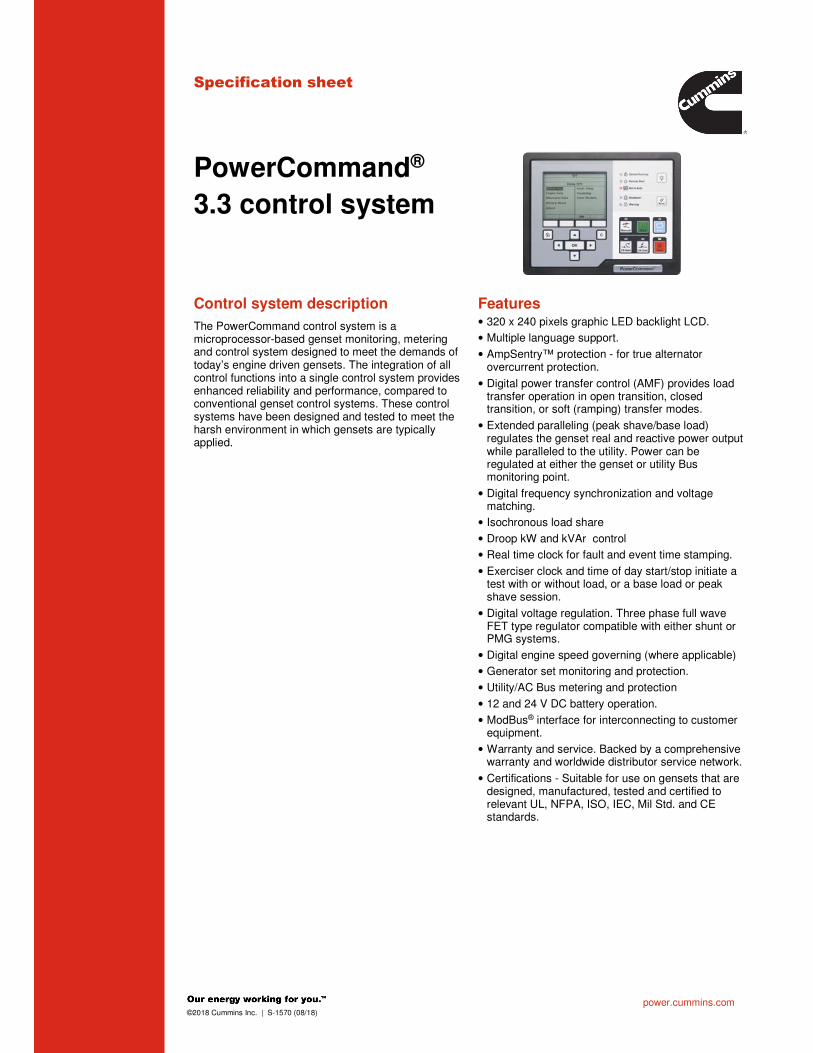
Specification sheet
PowerCommand®
3.3 control system
Control system description Features
The PowerCommand control system is a microprocessor-based genset monitoring, metering and control system designed to meet the demands of today’s engine driven gensets. The integration of all control functions into a single control system provides enhanced reliability and performance, compared to conventional genset control systems. These control systems have been designed and tested to meet the harsh environment in which gensets are typically applied.
• 320 x 240 pixels graphic LED backlight LCD.
• Multiple language support.
• AmpSentry™ protection - for true alternator overcurrent protection.
• Digital power transfer control (AMF) provides load transfer operation in open transition, closed transition, or soft (ramping) transfer modes.
• Extended paralleling (peak shave/base load) regulates the genset real and reactive power output while paralleled to the utility. Power can be regulated at either the genset or utility Bus monitoring point.
• Digital frequency synchronization and voltage matching.
• Isochronous load share
• Droop kW and kVAr control
• Real time clock for fault and event time stamping.
• Exerciser clock and time of day start/stop initiate a test with or without load, or a base load or peak shave session.
• Digital voltage regulation. Three phase full wave FET type regulator compatible with either shunt or PMG systems.
• Digital engine speed governing (where applicable)
• Generator set monitoring and protection.
• Utility/AC Bus metering and protection
• 12 and 24 V DC battery operation.
• ModBus® interface for interconnecting to customer equipment.
• Warranty and service. Backed by a comprehensive warranty and worldwide distributor service network.
• Certifications - Suitable for use on gensets that are designed, manufactured, tested and certified to relevant UL, NFPA, ISO, IEC, Mil Std. and CE standards.

power.cummins.com ©2018 Cummins Inc. | S-1570 (08/18)
PowerCommand digital genset control PCC 3300
Description
The PowerCommand genset control is suitable for use on a wide range of diesel and lean burn natural gas gensets in paralleling applications. The PowerCommand control is compatible with shunt or PMG excitation style. It is suitable for use with reconnectable or non-reconnectable generators, and it can be configured for any frequency, voltage and power connection from 120-600 VAC line-toline, 601-45,000 VAC with external PT.
Power for this control system is derived from the genset starting batteries. The control functions over a voltage range from 8 VDC to 30 VDC.
Features
• 12 and 24 VDC battery operation.
• Digital voltage regulation - Three phase full wave FET type regulator compatible with either shunt or PMG systems. Sensing is three phase.
• Digital engine speed governing (where applicable) - Provides isochronous frequency regulation.
• Full authority engine communications (where applicable) - Provides communication and control with the Engine Control Module (ECM).
• AmpSentry protection - for true alternator overcurrent protection.
• Genset monitoring - Monitors status of all critical engine and alternator functions.
• Digital genset metering (AC and DC).
• Genset battery monitoring system to sense and warn against a weak battery condition.
• Configurable for single or three phase AC metering.
• Engine starting - Includes relay drivers for starter, Fuel Shut Off (FSO), glow plug/spark ignition power and switch B+ applications.
• Genset protection – Protects engine and alternator.
• Real time clock for fault and event time stamping.
• Exerciser clock and time of day start/stop initiate a test with or without load, or a base load or peak shave session.
• Digital power transfer control (AMF) provides load transfer operation in open transition, closed transition, or soft (ramping) transfer modes.
• Extended paralleling (peak shave/base load) regulates the genset real and reactive power output while paralleled to the utility. Power can be regulated at either the genset or utility bus monitoring point.
• Digital frequency synchronization and voltage matching.
• Isochronous load share
• Droop kW and KVAr control
• Sync cCheck – The sync check function has adjustments for phase angle window, voltage window, frequency window and time delay.
• Utility/AC Bus metering and protection
• Advanced serviceability – using InPower™, a PC-based software service tool.
• Environmental protection – The control system is designed for reliable operation in harsh environments.
• The main control board is a fully encapsulated module that is protected from the elements.
• ModBus interface for interconnecting to customer equipment.
• Configurable inputs and outputs – Four discrete inputs and four dry contact relay outputs.
• Warranty and service – Backed by a comprehensive warranty and worldwide distributor service network.
• Certifications – Suitable for use on gensets that are designed, manufactured, tested and certified to relevant UL, NFPA, ISO, IEC, Mil Std. and CE standards.
Base control functions
HMI capability
Options – Local and remote HMI options.
Operator adjustments – The HMI includes provisions for many set up and adjustment functions.
Genset hardware data – Access to the control and software part number, genset rating in kVA and genset model number is provided from the HMI or InPower.
Data logs – Includes engine run time, controller on time, number of start attempts, total kilowatt hours, and load profile. (Control logs data indicating the operating hours at percent of rated kW load, in 5% increments. The data is presented on the operation panel based on total operating hours on the generator).
Fault history – Provides a record of the most recent fault conditions with control date and time stamp. Up to 32 events are stored in the control non-volatile memory.
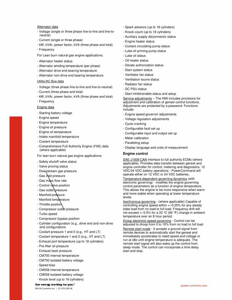
power.cummins.com ©2018 Cummins Inc. | S-1570 (08/18)
Alternator data
- Voltage (single or three phase line-to-line and line-to-neutral)
- Current (single or three phase)
- kW, kVAr, power factor, kVA (three phase and total)
- Frequency
For Lean burn natural gas engine applications:
- Alternator heater status
- Alternator winding temperature (per phase)
- Alternator drive end bearing temperature
- Alternator non-drive end bearing temperature
Utility/AC Bus data
- Voltage (three phase line-to-line and line-to-neutral)
- Current (three phase and total)
- kW, kVAr, power factor, kVA (three phase and total)
- Frequency
Engine data
- Starting battery voltage
- Engine speed
- Engine temperature
- Engine oil pressure
- Engine oil temperature
- Intake manifold temperature
- Coolant temperature
- Comprehensive Full Authority Engine (FAE) data (where applicable)
For lean burn natural gas engine applications:
- Safety shutoff valve status
- Valve proving status
- Downstream gas pressure
- Gas inlet pressure
- Gas mass flow rate
- Control valve position
- Gas outlet pressure
- Manifold pressure
- Manifold temperature
- Throttle position
- Compressor outlet pressure
- Turbo speed
- Compressor bypass position
- Cylinder configuration (e.g., drive end and non-drive end configurations
- Coolant pressure 1 and 2 (e.g., HT and LT)
- Coolant temperature 1 and 2 (e.g., HT and LT)
- Exhaust port temperature (up to 18 cylinders)
- Pre-filter oil pressure
- Exhaust back pressure
- CM700 internal temperature
- CM700 isolated battery voltage
- Speed bias
- CM558 internal temperature
- CM558 isolated battery voltage
- Knock level (up to 18 cylinders)
- Spark advance (up to 18 cylinders)
- Knock count (up to 18 cylinders)
- Auxiliary supply disconnector status
- Engine heater status
- Coolant circulating pump status
- Lube oil priming pump status
- Lube oil status
- Oil heater status
- Derate authorization status
- Start system status
- Ventilator fan status
- Ventilation louvre status
- Radiator fan status
- DC PSU status
- Start inhibit/enable status and setup
Service adjustments – The HMI includes provisions for adjustment and calibration of genset control functions. Adjustments are protected by a password. Functions include:
- Engine speed governor adjustments
- Voltage regulation adjustments
- Cycle cranking
- Configurable fault set up
- Configurable input and output set up
- Meter calibration
- Paralleling setup
- Display language and units of measurement
Engine control
SAE-J1939 CAN interface to full authority ECMs (where applicable). Provides data transfer between genset and engine controller for control, metering and diagnostics. 12 VDC/24 VDC battery operations - PowerCommand will operate either on 12 VDC or 24 VDC batteries.
Temperature dependent governing dynamics (with electronic governing) - modifies the engine governing control parameters as a function of engine temperature. This allows the engine to be more responsive when warm and more stable when operating at lower temperature levels.
Isochronous governing - (where applicable) Capable of controlling engine speed within +/-0.25% for any steady state load from no load to full load. Frequency drift will not exceed +/-0.5% for a 33 °C (60 °F) change in ambient temperature over an 8 hour period.
Droop electronic speed governing - Control can be adjusted to droop from 0 to 10% from no load to full load.
Remote start mode - It accepts a ground signal from remote devices to automatically start the genset and immediately accelerates to rated speed and voltage or run at idle until engine temperature is adequate. The remote start signal will also wake up the control from sleep mode. The control can incorporate a time delay start and stop.

power.cummins.com ©2018 Cummins Inc. | S-1570 (08/18)
Remote and local emergency stop - The control accepts a ground signal from a local (genset mounted) or remote (facility mounted) emergency stop switch to cause the genset to immediately shut down. The genset is prevented from running or cranking with the switch engaged. If in sleep mode, activation of either emergency stop switch will wake up the control.
Sleep mode - The control includes a configurable low current draw state to minimize starting battery current draw when the genset is not operating. The control can also be configured to go into a low current state while in auto for prime applications or applications without a battery charger.
Engine starting - The control system supports automatic engine starting. Primary and backup start disconnects are achieved by one of two methods: magnetic pickup or main alternator output frequency. The control also supports configurable glow plug control when applicable.
Cycle cranking - Is configurable for the number of starting cycles (1 to 7) and duration of crank and rest periods. Control includes starter protection algorithms to prevent the operator from specifying a starting sequence that might be damaging.
Time delay start and stop (cooldown) - Configurable for time delay of 0-300 seconds prior to starting after receiving a remote start signal and for time delay of 0-600 seconds prior to shut down after signal to stop in normal operation modes. Default for both time delay periods is 0 seconds.
For lean burn natural gas engine applications:
Engine start inhibit/enable – The function will allow application-specific processes to be started prior to the genset/engine start (e.g., pumps, boosters, etc.).
Alternator control
The control includes an integrated three phase line-to-line sensing voltage regulation system that is compatible with shunt or PMG excitation systems. The voltage regulation system is a three phase full wave rectified and has an FET output for good motor starting capability. Major system features include:
Digital output voltage regulation - Capable of regulating output voltage to within +/-1.0% for any loads between no load and full load. Voltage drift will not exceed +/-1.5% for a 40 ºC (104 ºF) change in temperature in an eight hour period. On engine starting or sudden load acceptance, voltage is controlled to a maximum of 5% overshoot over nominal level.
The automatic voltage regulator feature can be disabled to allow the use of an external voltage regulator.
Droop voltage regulation - Control can be adjusted to droop from 0-10% from no load to full load.
Torque-matched V/Hz overload control - The voltage roll-off set point and rate of decay (i.e. the slope of the V/Hz curve) is adjustable in the control.
Fault current regulation - PowerCommand will regulate the output current on any phase to a maximum of three times rated current under fault conditions for both single phase and three phase faults. In conjunction with a permanent magnet generator, it will provide three times rated current on all phases for motor starting and short circuit coordination purpose.
Paralleling functions
First Start SensorTM system – PowerCommand provides a unique control function that positively prevents multiple gensets from simultaneously closing to an isolated bus under black start conditions. The First Start Sensor system is a communication system between the gensets that allows the gensets to work together to determine which genset is a system should be the first to close to the bus. The system includes an independent backup function, so that if the primary system is disabled the required functions are still performed.
Synchronizing – Control incorporates a digital synchronizing function to force the genset to match the frequency, phase and voltage of another source such as a utility grid. The synchronizer includes provisions to provide proper operation even with highly distorted bus voltage waveforms. The synchronizer can match other sources over a range of 60-110% of nominal voltage and -24 to +6 Hz. The synchronizer function is configurable for slip frequency synchronizing for applications requiring a known direction of power flow at instant of breaker closure or for applications where phase synchronization performance is otherwise inadequate.
Load sharing control – The genset control includes an integrated load sharing control system for both real (kW) and reactive (kVar) loads when the genset(s) are operating on an isolated bus. The control system determines kW load on the engine and kVar load on the alternator as a percent of genset capacity, and then regulates fuel and excitation systems to maintain system and genset at the same percent of load without impacting voltage or frequency regulation. The control can also be configured for operation in droop mode for kW or Kvar load sharing.
Load govern control – When PowerCommand receives a signal indicating that the genset is paralleled with an infinite source such as a utility (mains) service, the genset will operate in load govern mode. In this mode the genset will synchronize and close to the bus, ramp to a pre-programmed kW and kVar load level, and then operate at that point. Control is adjustable for kW values from 0- 100% of Standby rating, and 0.7-1.0 power factor (lagging). Default setting is 80% of Standby and 1.0 power factor. The control includes inputs to allow independent control of kW and kVar load level by a remote device while in the load govern mode. The rate of load increase and decrease is also adjustable in the control. In addition, the control can be configured for operation in kW or kVAr load govern droop.
Load demand control – The control system includes the ability to respond to an external signal to initiate load demand operation. On command, the genset will ramp to no load, open its paralleling breaker, cool down, and shut down. On removal of the command, the genset will immediately start, synchronize, connect, and ramp to its share of the total load on the system.
Sync check – The sync check function decides when permissive conditions have been met to allow breaker closure. Adjustable criteria are: phase difference from 0.1-20 deg, frequency difference from 0.001-1.0 Hz, voltage difference from 0.5-10%, and a dwell time from 0.5-5.0 sec. Internally the sync check is used to perform closed transition operations. An external sync check output is also available.
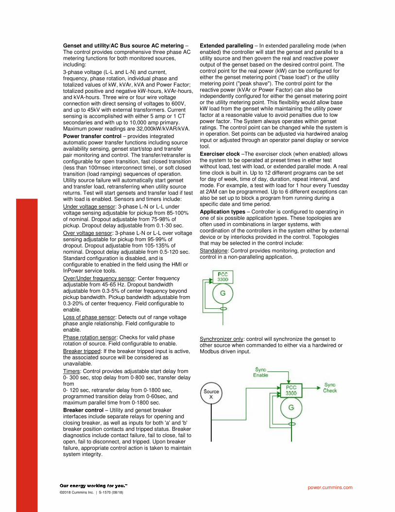
power.cummins.com ©2018 Cummins Inc. | S-1570 (08/18)
Genset and utility/AC Bus source AC metering – The control provides comprehensive three phase AC metering functions for both monitored sources, including:
3-phase voltage (L-L and L-N) and current, frequency, phase rotation, individual phase and totalized values of kW, kVAr, kVA and Power Factor; totalized positive and negative kW-hours, kVAr-hours, and kVA-hours. Three wire or four wire voltage connection with direct sensing of voltages to 600V, and up to 45kV with external transformers. Current sensing is accomplished with either 5 amp or 1 CT secondaries and with up to 10,000 amp primary. Maximum power readings are 32,000kW/kVAR/kVA.
Power transfer control – provides integrated automatic power transfer functions including source availability sensing, genset start/stop and transfer pair monitoring and control. The transfer/retransfer is configurable for open transition, fast closed transition (less than 100msec interconnect time), or soft closed transition (load ramping) sequences of operation. Utility source failure will automatically start genset and transfer load, retransferring when utility source returns. Test will start gensets and transfer load if test with load is enabled. Sensors and timers include:
Under voltage sensor: 3-phase L-N or L-L under voltage sensing adjustable for pickup from 85-100% of nominal. Dropout adjustable from 75-98% of pickup. Dropout delay adjustable from 0.1-30 sec.
Over voltage sensor: 3-phase L-N or L-L over voltage sensing adjustable for pickup from 95-99% of dropout. Dropout adjustable from 105-135% of nominal. Dropout delay adjustable from 0.5-120 sec. Standard configuration is disabled, and is configurable to enabled in the field using the HMI or InPower service tools.
Over/Under frequency sensor: Center frequency adjustable from 45-65 Hz. Dropout bandwidth adjustable from 0.3-5% of center frequency beyond pickup bandwidth. Pickup bandwidth adjustable from 0.3-20% of center frequency. Field configurable to enable.
Loss of phase sensor: Detects out of range voltage phase angle relationship. Field configurable to enable.
Phase rotation sensor: Checks for valid phase rotation of source. Field configurable to enable.
Breaker tripped: If the breaker tripped input is active, the associated source will be considered as unavailable.
Timers: Control provides adjustable start delay from 0- 300 sec, stop delay from 0-800 sec, transfer delay from 0- 120 sec, retransfer delay from 0-1800 sec, programmed transition delay from 0-60sec, and maximum parallel time from 0-1800 sec.
Breaker control – Utility and genset breaker interfaces include separate relays for opening and closing breaker, as well as inputs for both 'a' and 'b' breaker position contacts and tripped status. Breaker diagnostics include contact failure, fail to close, fail to open, fail to disconnect, and tripped. Upon breaker failure, appropriate control action is taken to maintain system integrity.
Extended paralleling – In extended paralleling mode (when enabled) the controller will start the genset and parallel to a utility source and then govern the real and reactive power output of the genset based on the desired control point. The control point for the real power (kW) can be configured for either the genset metering point ("base load") or the utility metering point ("peak shave"). The control point for the reactive power (kVAr or Power Factor) can also be independently configured for either the genset metering point or the utility metering point. This flexibility would allow base kW load from the genset while maintaining the utility power factor at a reasonable value to avoid penalties due to low power factor. The System always operates within genset ratings. The control point can be changed while the system is in operation. Set points can be adjusted via hardwired analog input or adjusted through an operator panel display or service tool.
Exerciser clock –The exerciser clock (when enabled) allows the system to be operated at preset times in either test without load, test with load, or extended parallel mode. A real time clock is built in. Up to 12 different programs can be set for day of week, time of day, duration, repeat interval, and mode. For example, a test with load for 1 hour every Tuesday at 2AM can be programmed. Up to 6 different exceptions can also be set up to block a program from running during a specific date and time period.
Application types – Controller is configured to operating in one of six possible application types. These topologies are often used in combinations in larger systems, with coordination of the controllers in the system either by external device or by interlocks provided in the control. Topologies that may be selected in the control include:
Standalone: Control provides monitoring, protection and control in a non-paralleling application.
Synchronizer only: control will synchronize the genset to other source when commanded to either via a hardwired or Modbus driven input.

power.cummins.com ©2018 Cummins Inc. | S-1570 (08/18)
Isolated Bus: allows the genset to perform a dead bus closure or synchronize to the bus and isochronously share kW and kVAR loads with other gensets.
Utility single: Control monitors one genset and utility. The control will automatically start and provide power to a load if the utility fails. The control will also resynchronize the genset back to the utility and provides extended paralleling capabilities.
Utility multiple: Supports all functionality of Isolated Bus and provides extended paralleling to the utility. Extended paralleling load set points follow a constant setting; dynamically follow an analog input, ModBus register or HMI.
Power transfer control: control operates a single genset/single utility transfer pair in open transition, fast closed transition, or soft closed transition. Extended paralleling functionality also provides base load and peak shave options.
Protective functions
On operation of a protective function the control will indicate a fault by illuminating the appropriate status LED on the HMI, as well as display the fault code and fault description on the LCD. The nature of the fault and time of occurrence are logged in the control. The service manual and InPower service tool provide service keys and procedures based on the service codes provided.
Protective functions include:
Battle short mode
When enabled and the battle short switch is active, the control will allow some shutdown faults to be bypassed. If a bypassed shutdown fault occurs, the fault code and description will still be annunciated, but the genset will not shutdown. This will be followed by a fail to shutdown fault. Emergency stop shutdowns and others that are critical for proper operation (or are handled by the engine ECM) are not bypassed. Please refer to the control application guide or manual for list of these faults.
Derate
The derate function reduces output power of the genset in response to a fault condition. If a derate command occurs while operating on an isolated bus, the control will issue commands to reduce the load on the genset via contact closures or ModBus. If a derate command occurs while in utility parallel mode, the control will actively reduce power by lowering the base load kW to the derated target kW.
Configurable alarm and status inputs
The control accepts up to four alarm or status inputs (configurable contact closed to ground or open) to indicate a configurable (customer-specified) condition. The control is programmable for warning, derate, shutdown, shutdown with cooldown or status indication and for labeling the input.
Emergency stop
Annunciated whenever either emergency stop signal is received from external switch.

power.cummins.com ©2018 Cummins Inc. | S-1570 (08/18)
General engine protection
Low and high battery voltage warning - Indicates status of battery charging system (failure) by continuously monitoring battery voltage.
Weak battery warning - The control system will test the battery each time the genset is signaled to start and indicate a warning if the battery indicates impending failure.
Fail to start (overcrank) shutdown - The control system will indicate a fault if the genset fails to start by the completion of the engine crack sequence.
Fail to crank shutdown - Control has signaled starter to crank engine but engine does not rotate.
Cranking lockout - The control will not allow the starter to attempt to engage or to crank the engine when the engine is rotating.
Fault simulation –The control in conjunction with InPower software, will accept commands to allow a technician to verify the proper operation of the control and its interface by simulating failure modes or by forcing the control to operate outside of its normal operating ranges. InPower also provides a complete list of faults and settings for the protective functions provided by the controller.
For lean burn natural gas engine applications:
Off load running (protection) – This feature protects the engine in the event the genset is being called to go off load for too long.
Hydro mechanical fuel system engine protection
Overspeed shutdown – Default setting is 115% of nominal Low lube oil pressure warning/shutdown – Level is preset (configurable with InPower or HMI) to match the capabilities of the engine used. Control includes time delays to prevent nuisance alarms.
High lube oil temperature warning/shutdown – Level is preset (configurable with InPower or HMI) to match the capabilities of the engine used. Control includes time delays to prevent nuisance alarms.
High engine temperature warning/shutdown – Level is preset (configurable with InPower or HMI) to match the capabilities of the engine used. Control includes time delays to prevent nuisance alarms.
Low coolant temperature warning – Indicates that engine temperature may not be high enough for a 10 second start or proper load acceptance.
Low coolant temperature warning – Can be set up to be a warning or shutdown.
High intake manifold temperature shutdown – Level is preset (configurable with InPower or HMI) to match the capabilities of the engine used. Control includes time delays to prevent nuisance alarms.
Full authority electronic engine protection
Engine fault detection is handled inside the engine ECM. Fault information is communicated via the SAE-J1939 data link for annunciation in the HMI.
Alternator protection
AmpSentry protective relay - A comprehensive monitoring and control system integral to the PowerCommand Control System that guards the electrical integrity of the alternator and power system by providing protection against a wide array of fault conditions in the genset or in the load. It also provides single and three phase fault current regulation so that downstream protective devices have the maximum current available to quickly clear fault conditions without subjecting the alternator to potentially catastrophic failure conditions. See document R1053 for a full size time over current curve. The control does not included protection required for interconnection to a utility (mains) service.
High AC voltage shutdown (59) - Output voltage on any phase exceeds preset values. Time to trip is inversely proportional to amount above threshold. Values adjustable from 105-125% of nominal voltage, with time delay adjustable from 0.1-10 seconds. Default value is 110% for 10 seconds.
Low AC voltage shutdown (27) - Voltage on any phase has dropped below a preset value. Adjustable over a range of 50-95% of reference voltage, time delay 2-20 seconds. Default value is 85% for 10 seconds. Function tracks reference voltage. Control does not nuisance trip when voltage varies due to the control directing voltage to drop, such as during a V/Hz roll-off or synchronizing.
Under frequency shutdown (81 u) - Genset output frequency cannot be maintained. Settings are adjustable from 2-10 Hz below reference governor set point, for a 5- 20 second time delay. Default: 6 Hz, 10 seconds. Under frequency protection is disabled when excitation is switched off, such as when engine is operating in idle speed mode.

power.cummins.com ©2018 Cummins Inc. | S-1570 (08/18)
Over frequency shutdown/warning (81o) - Genset is operating at a potentially damaging frequency level. Settings are adjustable from 2-10 Hz above nominal governor set point for a 1-20 second time delay. Default: 6 Hz, 20 seconds, disabled.
Overcurrent warning/shutdown (51) - Implementation of the thermal damage curve with instantaneous trip level calculated based on current transformer ratio and application power rating.
Loss of sensing voltage shutdown - Shutdown of genset will occur on loss of voltage sensing inputs to the control.
Field overload shutdown - Monitors field voltage to shutdown genset when a field overload condition occurs.
Over load (kW) warning - Provides a warning indication when engine is operating at a load level over a set point. Adjustment range: 80-140% of application rated kW, 0- 120 second delay. Defaults: 105%, 60 seconds.
Reverse power shutdown (32) - Adjustment range: 5-20% of Standby kW rating, delay 1-15 seconds. Default: 10%, 3 seconds.
Reverse Var shutdown - Shutdown level is adjustable: 15- 50% of rated Var output, delay 10-60 seconds. Default: 20%, 10 seconds.
Short circuit protection - Output current on any phase is more than 175% of rating and approaching the thermal damage point of the alternator. Control includes algorithms to protect alternator from repeated over current conditions over a short period of time.
Negative sequence overcurrent warning (46) – Control protects the generator from damage due to excessive imbalances in the three phase load currents and/or power factors.
Custom overcurrent warning/shutdown (51) – Control provides the ability to have a custom time overcurrent protection curve in addition to the AmpSentry protective relay function.
Ground fault overcurrent (51G) – Control detects a ground fault either by an external ground fault relay via a contact input or the control can measure the ground current from an external current transformer. Associated time delays and thresholds are adjustable via InPower or HMI.
Paralleling protection
Breaker fail to close warning: When the control signals a circuit breaker to close, it will monitor the breaker auxiliary contacts and verify that the breaker has closed. If the control does not sense a breaker closure within an adjustable time period after the close signal, the fail to close warning will be initiated.
Breaker fail to open warning: The control system monitors the operation of breakers that have been signalled to open. If the breaker does not open within and adjustable time delay, a Breaker Fail to Open warning is initiated.
Breaker position contact warning: The controller will monitor both ‘a’ and ‘b’ position contacts from the breaker. If the contacts disagree as to the breaker position, the breaker position contact warning will be initiated.
Breaker tripped warning: The control accepts inputs to monitor breaker trip / bell alarm contact and will initiate a breaker tripped warning if it should activate.
Fail to disconnect warning: In the controller is unable to open either breaker, a fail to disconnect warning is initiated. Typically this would be mapped to a configurable output, allowing an external device to trip a breaker.
Fail to synchronize warning: Indicates that the genset could not be brought to synchronization with the bus. Configurable for adjustable time delay of 10 -900 seconds, 120 default.
Phase sequence sensing warning: Verifies that the genset phase sequence matches the bus prior to allowing the paralleling breaker to close.
Maximum parallel time warning (power transfer control mode only): During closed transition load transfers, control independently monitors paralleled time. If time is exceeded, warning is initiated and genset is disconnected.
Bus or genset PT input calibration warning: The control system monitors the sensed voltage from the bus and genset output voltage potential transformers. When the paralleling breaker is closed, it will indicate a warning condition if the read values are different.
Field control interface
Input signals to the PowerCommand control include:
- Coolant level (where applicable)
- Fuel level (where applicable)
- Remote emergency stop
- Remote fault reset
- Remote start
- Rupture basin
- Start type signal
- Battle short
- Load demand stop
- Synchronize enable
- Genset circuit breaker inhibit
- Utility circuit breaker inhibit
- Single mode verify
- Transfer inhibit – prevent transfer to utility (in power transfer control mode)
- Retransfer inhibit – prevent retransfer to genset (in power transfer control mode)
- kW and kVAr load setpoints
- Configurable inputs - Control includes (4) input signals from customer discrete devices that are configurable for warning, shutdown or status indication, as well as message displayed
For lean burn natural gas engine applications:
- Gearbox oil pressure/temperature protection
- Fire fault
- Earth fault
- Differential fault
- DC power supply fault
- Genset Interface Box (GIB) isolator open fault
- Start inhibit/enable (x3)
- Radiator fan trip

power.cummins.com ©2018 Cummins Inc. | S-1570 (08/18)
- Ventilator fan trip
- Ventilation louvers closed
- Start system trip
- Alternator heater trip
- Alternator heater status
- Alternator winding temperature (PT100 RTDx3)
- Alternator drive end bearing temperature (PT100 RTD)
- Alternator non-drive end bearing temperature (PT100 RTD)
Output signals from the PowerCommand control include:
- Load dump signal: Operates when the genset is in an overload condition.
- Delayed off signal: Time delay based output which will continue to remain active after the control has removed the run command. Adjustment range: 0 - 120 seconds. Default: 0 seconds.
- Configurable relay outputs: Control includes (4) relay output contacts (3 A, 30 VDC). These outputs can be configured to activate on any control warning or shutdown fault as well as ready to load, not in auto, common alarm, common warning and common shutdown.
- Ready to load (genset running) signal: Operates when the genset has reached 90% of rated speed and voltage and latches until genset is switched to off or idle mode.
- Paralleling circuit breaker relays outputs: Control includes (4) relay output contacts (3.5 A, 30 VDC) for opening and closing of the genset and utility breakers.
For lean burn natural gas engine applications:
- Start inhibit/enable event
- Emergency stop event
- Ventilator fan run control
- Louvre control
- Radiator fan control
- Alternator heater control
- Engine at idle speed event
Communications connections include:
- PC tool interface: This RS-485 communication port allows the control to communicate with a personal computer running InPower software.
- ModBus RS-485 port: Allows the control to communicate with external devices such as PLCs using ModBus protocol.
Note - An RS-232 or USB to RS-485 converter is required for communication between PC and control.
- Networking: This RS-485 communication port allows connection from the control to the other Cummins products.
Mechanical drawing
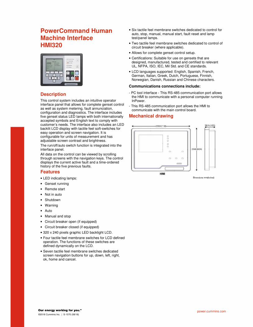
power.cummins.com ©2018 Cummins Inc. | S-1570 (08/18)
PowerCommand Human Machine Interface HMI320
Description
This control system includes an intuitive operator interface panel that allows for complete genset control as well as system metering, fault annunciation, configuration and diagnostics. The interface includes five genset status LED lamps with both internationally accepted symbols and English text to comply with customer’s needs. The interface also includes an LED backlit LCD display with tactile feel soft-switches for easy operation and screen navigation. It is configurable for units of measurement and has adjustable screen contrast and brightness.
The run/off/auto switch function is integrated into the interface panel.
All data on the control can be viewed by scrolling through screens with the navigation keys. The control displays the current active fault and a time-ordered history of the five previous faults.
Features
• LED indicating lamps:
• Genset running
• Remote start
• Not in auto
• Shutdown
• Warning
• Auto
• Manual and stop
• Circuit breaker open (if equipped)
• Circuit breaker closed (if equipped)
• 320 x 240 pixels graphic LED backlight LCD.
• Four tactile feel membrane switches for LCD defined operation. The functions of these switches are defined dynamically on the LCD.
• Seven tactile feel membrane switches dedicated screen navigation buttons for up, down, left, right, ok, home and cancel.
• Six tactile feel membrane switches dedicated to control for auto, stop, manual, manual start, fault reset and lamp test/panel lamps.
• Two tactile feel membrane switches dedicated to control of circuit breaker (where applicable).
• Allows for complete genset control setup.
• Certifications: Suitable for use on gensets that are designed, manufactured, tested and certified to relevant UL, NFPA, ISO, IEC, Mil Std. and CE standards.
• LCD languages supported: English, Spanish, French, German, Italian, Greek, Dutch, Portuguese, Finnish, Norwegian, Danish, Russian and Chinese characters.
Communications connections include:
- PC tool interface - This RS-485 communication port allows the HMI to communicate with a personal computer running InPower.
- This RS-485 communication port allows the HMI to communicate with the main control board.
Mechanical drawing

For more information contact your local Cummins distributor or visit power.cummins.com
©2018 Cummins Inc. All rights reserved. Cummins is a registered trademark of Cummins Inc. PowerCommand, AmpSentry, InPower and “Our energy working for you.” are trademarks of Cummins Inc. Other company, product, or service names may be trademarks or service marks of others. Specifications are subject to change without notice. S-1570 (08/18)
Software
InPower (beyond 6.5 version) is a PC-based software service tool that is designed to directly communicate to PowerCommand gensets and transfer switches, to facilitate service and monitoring of these products.
Environment
The control is designed for proper operation without recalibration in ambient temperatures from -40 ºC (-40 ºF) to +70 ºC (158 ºF), and for storage from -55 ºC (-67 ºF) to +80 ºC (176 ºF). Control will operate with humidity up to 95%, non-condensing.
The HMI is designed for proper operation in ambient temperatures from -20 ºC (-4 ºF) to +70 ºC (158 ºF), and for storage from -30 ºC (-22 ºF) to +80 ºC (176 ºF).
The control board is fully encapsulated to provide superior resistance to dust and moisture. Display panel has a single membrane surface, which is impervious to effects of dust, moisture, oil and exhaust fumes. This panel uses a sealed membrane to provide long reliable service life in harsh environments.
The control system is specifically designed and tested for resistance to RFI/EMI and to resist effects of vibration to provide a long reliable life when mounted on a genset. The control includes transient voltage surge suppression to provide compliance to referenced standards.
Certifications
PowerCommand meets or exceeds the requirements of the following codes and standards:
- NFPA 110 for level 1 and 2 systems.
- ISO 8528-4: 1993 compliance, controls and switchgear.
- CE marking: The control system is suitable for use on generator sets to be CE-marked.
- EN 50081-1,2 residential/light industrial emissions or industrial emissions.
- EN 50082-1,2 residential/light industrial or industrial susceptibility.
- ISO 7637-2, level 2; DC supply surge voltage test.
- Mil Std 202C, Method 101 and ASTM B117: Salt fog test.
- UL 508 recognized or Listed and suitable for use on UL 2200 Listed generator sets.
- CSA C282-M1999 compliance
- CSA 22.2 No. 14 M91 industrial controls.
- PowerCommand control systems and generator sets are designed and manufactured in ISO 9001 certified facilities.
Warranty
All components and subsystems are covered by an express limited one year warranty. Other optional and extended factory warranties and local distributor maintenance agreements are available.

Attachment D.3.2 – Caterpillar 400 kW Diesel Generator Specifications

Cat® C18 DIESEL GENERATOR SETS
Standby & Prime: 60Hz, 480V Engine Model Cat® C18 ATTACTM In-line 6, 4-cycle
diesel Bore x Stroke 145mm x 183mm (5.7in x 7.2in)
Displacement 18.13 L (1106.3 in³)
Compression Ratio 16.1:1
Aspiration Turbocharged Air-to-Air Aftercooled
Fuel Injection System Electronic Unit Injection
Governor Electronic ADEM™ A4
Model Standby Prime Emission Strategy C18 625 kVA, 500 ekW 569 kVA, 455 ekW US EPA TIER IV
Final Non-Road PACKAGE PERFORMANCE
Performance Standby Prime
Frequency 60 Hz 60 Hz
Genset Power Rating 625 kVA 569 kVA Gen set power rating with fan @ 0.8 power factor 500 ekW 455 ekW
Fuelling strategy US EPA TIER IV Final Non-Road US EPA TIER IV Final Non-Road
Performance Number EM1017 EM1112
Fuel Consumption
100% load with fan 135.6 L/hr, 35.8 gal/hr 122.6 L/hr, 32.4 gal/hr
75% load with fan 103.3 L/hr, 27.3 gal/hr 93.6 L/hr, 24.7 gal/hr
50% load with fan 73.5 L/hr, 19.4 gal/hr 67.0 L/hr, 17.7 gal/hr
25% load with fan 45.5 L/hr, 12.0 gal/hr 41.8 L/hr, 11.0 gal/hr
Cooling System1
Radiator air flow restriction (system) 0.12 kPa, 0.48 in. Water 0.12 kPa, 0.48 in. Water
Radiator air flow 804 m3/min, 28393 cfm 804 m3/min, 28393 cfm
Engine coolant capacity 26.9 L, 7.1 gal 26.9 L, 7.1 gal
Radiator coolant capacity 61 L, 16.11 gal 61 L, 16.11 gal
Total coolant capacity 87.9 L, 23.2 gal 87.9 L, 23.2 gal
Inlet Air
Combustion air inlet flow rate 37.9 m³/min, 1340 cfm 36.3 m³/min, 1208 cfm
Max. Allowable Combustion Air Inlet Temp 50 °C, 122 °F 50 °C, 122 °F
Exhaust System
Exhaust stack gas temperature 447 °C, 836.8 °F 426.3°C, 799.3 °F
Exhaust gas flow rate 69.8 m³/min, 2465.3 cfm 66.5 m³/min, 2349.7 cfm Exhaust system backpressure (maximum allowable) 10.0 kPa, 40.0 in. water 10.0 kPa, 40.0 in. water Heat Rejection
Heat rejection to jacket water 283 kW, 16110 Btu/min 256 kW, 14548 Btu/min
Heat rejection to exhaust (total) 514 kW, 29204 Btu/min 462 kW, 26276 Btu/min
Heat rejection to aftercooler 113 kW, 6454 Btu/min 101 kW, 5721 Btu/min Heat rejection to atmosphere from engine 28 kW, 1603 Btu/min 26.1 kW, 1483 Btu/min Heat rejection to atmosphere from Generator 29 kW, 1621 Btu/min 25.5 kW, 1450 Btu/min
LEHE1710-ISO3046 1/2
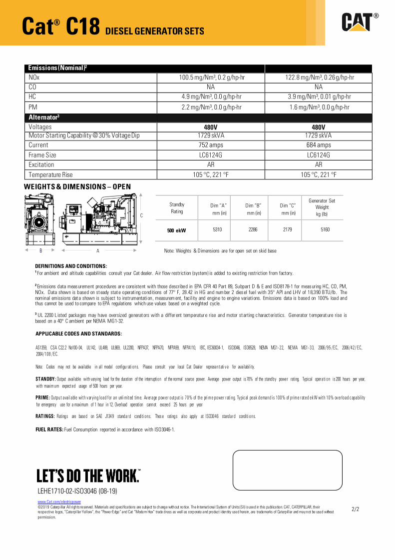
Cat® C18 DIESEL GENERATOR SETS
Emissions (Nominal)2
NOx 100.5 mg/Nm³, 0.2 g/hp-hr 122.8 mg/Nm³, 0.26 g/hp-hr CO NA NA HC 4.9 mg/Nm³, 0.0 g/hp-hr 3.9 mg/Nm³, 0.01 g/hp-hr
PM 2.2 mg/Nm³, 0.0 g/hp-hr 1.6 mg/Nm³, 0.0 g/hp-hr Alternator3
Voltages 480V 480V Motor Starting Capability @ 30% Voltage Dip 1729 skVA 1729 skVA Current 752 amps 684 amps Frame Size LC6124G LC6124G Excitation AR AR Temperature Rise 105 °C, 221 °F 105 °C, 221 °F
APPLICABLE CODES AND STANDARDS:
AS1359, CSA C22.2 No100- 04, UL142, UL489, UL869, UL2200, NFPA37, NFPA70, NFPA99, NFPA110, IBC, IEC60034- 1, ISO3046, ISO8528, NEMA MG1- 22, NEMA MG1- 33, 2006/95 /EC, 2006/42/ EC, 2004/108 /EC.
Note: Codes may not be available in all model configur ati ons. Please consult your local Cat Dealer represent ati v e for availability.
ST ANDBY: Output available with varying load for the duration of the interruption of the normal source power. Average power output is 70% of the standby power rating. Typical oper ati on is 200 hours per year, with maxim um expect ed usage of 500 hours per year.
PRIME : Output avail able wit h v ar ying load f or an unli mit ed tim e. Av er age pow er out put is 70% of the pri m e power r ati ng. Ty pic al peak demand is 100% of prim e r at ed ek W wit h 10% ov erload c apability for emergency use for a maximum of 1 hour in 12. Overload operation cannot exceed 25 hours per year
RAT INGS: Ratings are based on SAE J1349 standar d conditi ons. Thes e ratings also apply at ISO3046 standar d conditi ons.
FUEL RATES: Fuel Consumption reported in accordance with ISO3046-1.
Standby Rating
Dim “A” mm (in)
Dim “B” mm (in)
Dim “C” mm (in)
Generator Set Weight kg (lb)
500 ekW 5310 2286 2179 5160
DEFINITIONS AND CONDITIONS: 1 For ambient and altitude capabilities consult your Cat dealer. Air flow restriction (system) is added to existing restriction from factory.
2 Emissions data measurement procedures ar e consistent with those described in EPA CFR 40 Part 89, Subpart D & E and ISO8178-1 for measuring HC, CO, PM, NOx. Data shown is based on st eady stat e operating conditions of 77° F, 28.42 in HG and num ber 2 diesel fuel with 35° API and LHV of 18,390 BTU/lb. The nominal emissions dat a shown is subject to instrumentation, measurem ent, facil ity and engine to engine variations. Emissions data is based on 100% load and thus cannot be used to compare to EPA regulations which use values based on a weighted cycle.
3 UL 2200 L isted packages may have oversized generat ors with a differ ent temperatur e rise and motor st arting charact eristics. Generator t emperat ure rise is based on a 40° C ambient per NEMA MG1-32.
Note: Weights & Dimensions are for open set on skid base
WEIGHTS & DIMENSIONS – OPEN
www.Cat.com/electricpower ©2019 Caterpillar All rights reserved. Materials and specifications are subject to change without notice. The International System of Units (SI) is used in this publication. CAT, CATERPILLAR, their respective logos, “Caterpillar Yellow”, the “Power Edge” and Cat “Modern Hex” trade dress as well as corporate and product identity used herein, are trademarks of Caterpillar and may not be used without permission.
LEHE1710-02-ISO3046 (08-19)
2/2

Attachment D.3.3 – MAC Baghouse Efficiency


Attachment D.4.1 – Emissions Calculations and Factors
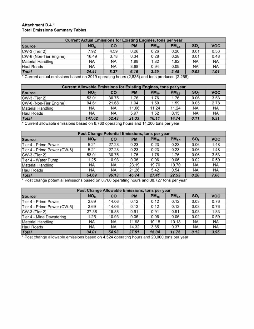
Attachment D.4.1Total Emissions Summary Tables
Source NOX CO PM PM10 PM2.5 SO2 VOCCW-3 (Tier 2) 7.92 4.59 0.26 0.26 0.26 0.01 0.53CW-6 (Non-Tier Engine) 16.49 3.78 0.34 0.28 0.28 0.01 0.48Material Handling NA NA 1.89 1.82 1.82 NA NAHaul Roads NA NA 3.68 0.94 0.09 NA NATotal 24.41 8.37 6.16 3.29 2.45 0.02 1.01* Current actual emissions based on 2019 operating hours (2,835) and tons produced (2,265).
Source NOX CO PM PM10 PM2.5 SO2 VOCCW-3 (Tier 2) 53.01 30.75 1.76 1.76 1.76 0.06 3.53CW-6 (Non-Tier Engine) 94.61 21.68 1.94 1.59 1.59 0.05 2.78Material Handling NA NA 11.66 11.24 11.24 NA NAHaul Roads NA NA 5.97 1.52 0.15 NA NATotal 147.62 52.43 21.33 16.11 14.74 0.11 6.31* Current allowable emissions based on 8,760 operating hours and 14,200 tons per year
Source NOX CO PM PM10 PM2.5 SO2 VOCTier 4 - Prime Power 5.21 27.23 0.23 0.23 0.23 0.06 1.48Tier 4 - Prime Power (CW-6) 5.21 27.23 0.23 0.23 0.23 0.06 1.48CW-3 (Tier 2) 53.01 30.75 1.76 1.76 1.76 0.06 3.53Tier 4 - Water Pump 1.25 10.93 0.06 0.06 0.06 0.02 0.59Material Handling NA NA 23.19 19.70 19.70 NA NAHaul Roads NA NA 21.26 5.42 0.54 NA NATotal 64.69 96.13 46.74 27.41 22.53 0.20 7.08* Post change potential emissions based on 8,760 operating hours and 38,727 tons per year
Source NOX CO PM PM10 PM2.5 SO2 VOCTier 4 - Prime Power 2.69 14.06 0.12 0.12 0.12 0.03 0.76Tier 4 - Prime Power (CW-6) 2.69 14.06 0.12 0.12 0.12 0.03 0.76CW-3 (Tier 2) 27.38 15.88 0.91 0.91 0.91 0.03 1.83Tier 4 - Mine Dewatering 1.25 10.93 0.06 0.06 0.06 0.02 0.59Material Handling NA NA 11.98 10.18 10.18 NA NAHaul Roads NA NA 14.32 3.65 0.37 NA NATotal 34.01 54.93 27.51 15.04 11.75 0.12 3.95* Post change allowable emissions based on 4,524 operating hours and 20,000 tons per year
Current Actual Emissions for Existing Engines, tons per year
Current Allowable Emissions for Existing Engines, tons per year
Post Change Potential Emissions, tons per year
Post Change Allowable Emissions, tons per year
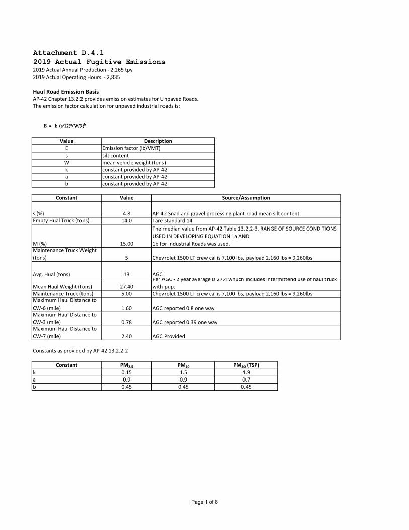
Attachment D.4.12019 Actual Fugitive Emissions2019 Actual Annual Production ‐ 2,265 tpy2019 Actual Operating Hours ‐ 2,835
Haul Road Emission BasisAP‐42 Chapter 13.2.2 provides emission estimates for Unpaved Roads.The emission factor calculation for unpaved industrial roads is:
ValueEsWkab
Constant Value
s (%) 4.8Empty Hual Truck (tons) 14.0
M (%) 15.00Maintenance Truck Weight (tons) 5
Avg. Hual (tons) 13
Mean Haul Weight (tons) 27.40Maintenance Truck (tons) 5.00Maximum Haul Distance to CW‐6 (mile) 1.60Maximum Haul Distance to CW‐3 (mile) 0.78Maximum Haul Distance to CW‐7 (mile) 2.40
Constants as provided by AP‐42 13.2.2‐2
Constant PM2.5 PM10 PM30 (TSP)
k 0.15 1.5 4.9a 0.9 0.9 0.7b 0.45 0.45 0.45
AGC reported 0.39 one way
AGC Provided
Chevrolet 1500 LT crew cal is 7,100 lbs, payload 2,160 lbs = 9,260lbs
AGC reported 0.8 one way
AGCPer AGC ‐ 2 year average is 27.4 whuch includes intermittend use of haul truck with pup.
The median value from AP‐42 Table 13.2.2‐3. RANGE OF SOURCE CONDITIONS USED IN DEVELOPING EQUATION 1a AND1b for Industrial Roads was used.
Chevrolet 1500 LT crew cal is 7,100 lbs, payload 2,160 lbs = 9,260lbs
AP‐42 Snad and gravel processing plant road mean silt content.Tare standard 14
constant provided by AP‐42
Source/Assumption
constant provided by AP‐42constant provided by AP‐42
silt contentmean vehicle weight (tons)
DescriptionEmission factor (lb/VMT)
Page 1 of 8

2019 Actual Fugitive Emissions
Calculated Emission Factor
lb/Vehicle Mile
Traveled (Haul
Truck)
lb/Vehicle Mile Traveled
(Maintenance and
Worker Truck)
PM2.5 0.18 0.08PM10 1.78 0.83PM30 (TSP) 6.98 3.25
Site
Number of Haul
Truck Trips/day
(actual based on
mine schedule) Actual Hauls/year Maintenance trips/year Worker trips/year
CW‐6 1 208 52 452CW‐3 1 208 52 452CW‐7 0 0 0 0
Transport Emissions PM2.5 PM10 PM30 (TSP)
CW‐6 0.03 0.30 1.16CW‐3 0.01 0.14 0.57CW‐7 0.00 0.00 0.00Actual 0.04 0.44 1.73
Maintenance Emissions PM2.5 PM10 PM30 (TSP)
CW‐6 0.003 0.03 0.14CW‐3 0.002 0.02 0.07CW‐7 0.000 0.00 0.00Actual 0.01 0.05 0.20
Worker Emissions PM2.5 PM10 PM30 (TSP)
CW‐6 0.03 0.30 1.17CW‐3 0.01 0.15 0.57CW‐7 0.00 0.00 0.00Actual 0.04 0.45 1.75
PM2.5 PM10 PM30 (TSP)
Total Emissions (TPY) 0.09 0.94 3.68
Page 2 of 8

Attachment D.4.1Current Allowable Fugitive EmissionPotential Annual Production ‐ 14,200 tpyPotential Post Change Annual Operating Hours ‐ 8,760
Haul Road Emission BasisAP‐42 Chapter 13.2.2 provides emission estimates for Unpaved Roads.The emission factor calculation for unpaved industrial roads is:
ValueEsWkab
Constant Value
s (%) 4.8Empty Hual Truck (tons) 14.0
M (%) 15.00Maintenance Truck Weight (tons) 5
Avg. Hual (tons) 13
Mean Haul Weight (tons) 27.40Maintenance Truck (tons) 5.00Maximum Haul Distance to CW‐6 (mile) 1.60Maximum Haul Distance to CW‐3 (mile) 0.78Maximum Haul Distance to CW‐7 (mile) 2.40
Constants as provided by AP‐42 13.2.2‐2
Constant PM2.5 PM10 PM30 (TSP)
k 0.15 1.5 4.9a 0.9 0.9 0.7b 0.45 0.45 0.45
AGC reported 0.39 one way
AGC Provided
Chevrolet 1500 LT crew cal is 7,100 lbs, payload 2,160 lbs = 9,260lbs
AGC reported 0.8 one way
AGCPer AGC ‐ 2 year average is 27.4 whuch includes intermittend use of haul truck with pup.
The median value from AP‐42 Table 13.2.2‐3. RANGE OF SOURCE CONDITIONS USED IN DEVELOPING EQUATION 1a AND1b for Industrial Roads was used.
Chevrolet 1500 LT crew cal is 7,100 lbs, payload 2,160 lbs = 9,260lbs
AP‐42 Snad and gravel processing plant road mean silt content.Tare standard 14
constant provided by AP‐42
Source/Assumption
constant provided by AP‐42constant provided by AP‐42
silt contentmean vehicle weight (tons)
DescriptionEmission factor (lb/VMT)
Page 3 of 8

Calculated Emission Factor
lb/Vehicle Mile
Traveled (Haul
Truck)
lb/Vehicle Mile Traveled
(Maintenance and
Worker Truck)
PM2.5 0.18 0.08PM10 1.78 0.83PM30 (TSP) 6.98 3.25
Site
Number of Haul
Truck Trips/day
(actual based on
mine schedule) Actual Hauls/year Maintenance trips/year Worker trips/year
CW‐6 2 416 52 452CW‐3 3 624 52 452CW‐7 0 0 0 0
Transport Emissions PM2.5 PM10 PM30 (TSP)
CW‐6 0.06 0.59 2.32CW‐3 0.04 0.43 1.70CW‐7 0.00 0.00 0.00Actual 0.10 1.03 4.02
Maintenance Emissions PM2.5 PM10 PM30 (TSP)
CW‐6 0.003 0.03 0.14CW‐3 0.002 0.02 0.07CW‐7 0.000 0.00 0.00Actual 0.01 0.05 0.20
Worker Emissions PM2.5 PM10 PM30 (TSP)
CW‐6 0.03 0.30 1.17CW‐3 0.01 0.15 0.57CW‐7 0.00 0.00 0.00Actual 0.04 0.45 1.75
PM2.5 PM10 PM30 (TSP)
Total Emissions (TPY) 0.15 1.52 5.97
Page 4 of 8

Attachment D.4.1Post Change Allowable Fugitive EmissionsProposed Annual Production ‐ 20,000 tpyProposed Post Change Annual Operating Hours ‐ 4,524
Haul Road Emission BasisAP‐42 Chapter 13.2.2 provides emission estimates for Unpaved Roads.The emission factor calculation for unpaved industrial roads is:
ValueEsWkab
Constant Value
s (%) 4.8Empty Hual Truck (tons) 14.0
M (%) 15.00Maintenance Truck Weight (tons) 5
Avg. Hual (tons) 13
Mean Haul Weight (tons) 27.40Maintenance Truck (tons) 5.00Maximum Haul Distance to CW‐6 (mile) 1.60Maximum Haul Distance to CW‐3 (mile) 0.78Maximum Haul Distance to CW‐7 (mile) 2.40
Constants as provided by AP‐42 13.2.2‐2
Constant PM2.5 PM10 PM30 (TSP)
k 0.15 1.5 4.9a 0.9 0.9 0.7b 0.45 0.45 0.45
AGC reported 0.39 one way
AGC Provided
Chevrolet 1500 LT crew cal is 7,100 lbs, payload 2,160 lbs = 9,260lbs
AGC reported 0.8 one way
AGCPer AGC ‐ 2 year average is 27.4 whuch includes intermittend use of haul truck with pup.
The median value from AP‐42 Table 13.2.2‐3. RANGE OF SOURCE CONDITIONS USED IN DEVELOPING EQUATION 1a AND1b for Industrial Roads was used.
Chevrolet 1500 LT crew cal is 7,100 lbs, payload 2,160 lbs = 9,260lbs
AP‐42 Snad and gravel processing plant road mean silt content.Tare standard 14
constant provided by AP‐42
Source/Assumption
constant provided by AP‐42constant provided by AP‐42
silt contentmean vehicle weight (tons)
DescriptionEmission factor (lb/VMT)
Page 5 of 8

Post Change Allowable Fugitive Emissions
Calculated Emission Factor
lb/Vehicle Mile
Traveled (Haul
Truck)
lb/Vehicle Mile Traveled
(Maintenance and
Worker Truck)
PM2.5 0.18 0.08PM10 1.78 0.83PM30 (TSP) 6.98 3.25
Site
Number of Haul
Truck Trips/day
(actual based on
mine schedule) Actual Hauls/year Maintenance trips/year Worker trips/year
CW‐6 3 624 52 452CW‐3 3 624 52 452CW‐7 2 416 52 452
Transport Emissions PM2.5 PM10 PM30 (TSP)
CW‐6 0.09 0.89 3.48CW‐3 0.04 0.43 1.70CW‐7 0.13 1.33 5.23Actual 0.27 2.65 10.41
Maintenance Emissions PM2.5 PM10 PM30 (TSP)
CW‐6 0.00 0.03 0.14CW‐3 0.00 0.02 0.07CW‐7 0.01 0.05 0.20Actual 0.01 0.10 0.40
Worker Emissions PM2.5 PM10 PM30 (TSP)
CW‐6 0.03 0.30 1.17CW‐3 0.01 0.15 0.57CW‐7 0.04 0.45 1.76Actual 0.09 0.89 3.51
PM2.5 PM10 PM30 (TSP)
Total Emissions (TPY) 0.37 3.65 14.32
Page 6 of 8

Attachment D.4.1Post Change Potential Fugitive EmissionsPotential Annual Production ‐ 38,727 tpyPotential Post Change Annual Operating Hours ‐ 8,760
Haul Road Emission BasisAP‐42 Chapter 13.2.2 provides emission estimates for Unpaved Roads.The emission factor calculation for unpaved industrial roads is:
ValueEsWkab
Constant Value
s (%) 4.8Empty Hual Truck (tons) 14.0
M (%) 15.00Maintenance Truck Weight (tons) 5
Avg. Hual (tons) 13
Mean Haul Weight (tons) 27.40Maintenance Truck (tons) 5.00Maximum Haul Distance to CW‐6 (mile) 1.60Maximum Haul Distance to CW‐3 (mile) 0.78Maximum Haul Distance to CW‐7 (mile) 2.40
Constants as provided by AP‐42 13.2.2‐2
Constant PM2.5 PM10 PM30 (TSP)
k 0.15 1.5 4.9a 0.9 0.9 0.7b 0.45 0.45 0.45
AGC reported 0.39 one way
AGC Provided
Chevrolet 1500 LT crew cal is 7,100 lbs, payload 2,160 lbs = 9,260lbs
AGC reported 0.8 one way
AGCPer AGC ‐ 2 year average is 27.4 whuch includes intermittend use of haul truck with pup.
The median value from AP‐42 Table 13.2.2‐3. RANGE OF SOURCE CONDITIONS USED IN DEVELOPING EQUATION 1a AND1b for Industrial Roads was used.
Chevrolet 1500 LT crew cal is 7,100 lbs, payload 2,160 lbs = 9,260lbs
AP‐42 Snad and gravel processing plant road mean silt content.Tare standard 14
constant provided by AP‐42
Source/Assumption
constant provided by AP‐42constant provided by AP‐42
silt contentmean vehicle weight (tons)
DescriptionEmission factor (lb/VMT)
Page 7 of 8
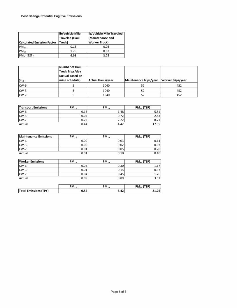
Post Change Potential Fugitive Emissions
Calculated Emission Factor
lb/Vehicle Mile
Traveled (Haul
Truck)
lb/Vehicle Mile Traveled
(Maintenance and
Worker Truck)
PM2.5 0.18 0.08PM10 1.78 0.83PM30 (TSP) 6.98 3.25
Site
Number of Haul
Truck Trips/day
(actual based on
mine schedule) Actual Hauls/year Maintenance trips/year Worker trips/year
CW‐6 5 1040 52 452CW‐3 5 1040 52 452CW‐7 5 1040 52 452
Transport Emissions PM2.5 PM10 PM30 (TSP)
CW‐6 0.15 1.48 5.81CW‐3 0.07 0.72 2.83CW‐7 0.22 2.22 8.71Actual 0.44 4.42 17.35
Maintenance Emissions PM2.5 PM10 PM30 (TSP)
CW‐6 0.00 0.03 0.14CW‐3 0.00 0.02 0.07CW‐7 0.01 0.05 0.20Actual 0.01 0.10 0.40
Worker Emissions PM2.5 PM10 PM30 (TSP)
CW‐6 0.03 0.30 1.17CW‐3 0.01 0.15 0.57CW‐7 0.04 0.45 1.76Actual 0.09 0.89 3.51
PM2.5 PM10 PM30 (TSP)
Total Emissions (TPY) 0.54 5.42 21.26
Page 8 of 8
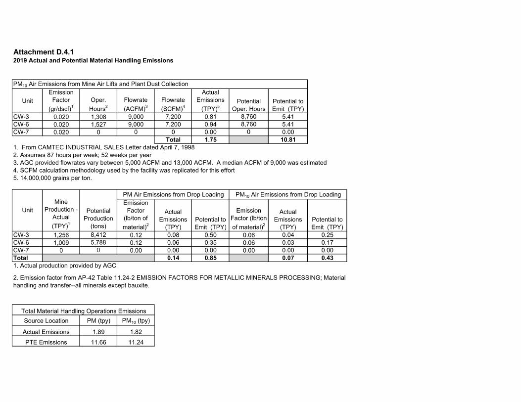
Attachment D.4.12019 Actual and Potential Material Handling Emissions
UnitEmission
Factor (gr/dscf)1
Oper. Hours2
Flowrate (ACFM)3
Flowrate (SCFM)4
Actual Emissions
(TPY)5Potential
Oper. HoursPotential to Emit (TPY)
CW-3 0.020 1,308 9,000 7,200 0.81 8,760 5.41CW-6 0.020 1,527 9,000 7,200 0.94 8,760 5.41CW-7 0.020 0 0 0 0.00 0 0.00
Total 1.75 10.811. From CAMTEC INDUSTRIAL SALES Letter dated April 7, 19982. Assumes 87 hours per week; 52 weeks per year3. AGC provided flowrates vary between 5,000 ACFM and 13,000 ACFM. A median ACFM of 9,000 was estimated4. SCFM calculation methodology used by the facility was replicated for this effort5. 14,000,000 grains per ton.
Emission Factor
(lb/ton of material)2
Actual Emissions
(TPY)Potential to Emit (TPY)
Emission Factor (lb/ton of material)2
Actual Emissions
(TPY)Potential to Emit (TPY)
CW-3 1,256 8,412 0.12 0.08 0.50 0.06 0.04 0.25CW-6 1,009 5,788 0.12 0.06 0.35 0.06 0.03 0.17CW-7 0 0 0.00 0.00 0.00 0.00 0.00 0.00Total 0.14 0.85 0.07 0.431. Actual production provided by AGC
PM (tpy) PM10 (tpy)
1.89 1.8211.66 11.24
Actual EmissionsPTE Emissions
PM10 Air Emissions from Mine Air Lifts and Plant Dust Collection
PM10 Air Emissions from Drop Loading
Total Material Handling Operations EmissionsSource Location
2. Emission factor from AP-42 Table 11.24-2 EMISSION FACTORS FOR METALLIC MINERALS PROCESSING; Materialhandling and transfer--all minerals except bauxite.
PM Air Emissions from Drop Loading
Potential Production
(tons)
Mine Production -
Actual (TPY)1
Unit

Attachment D.4.1Potential Material Handling Emissions
UnitEmission
Factor (gr/dscf)1
Oper. Hours2
Flowrate (ACFM)3
Flowrate (SCFM)4
Actual Emissions
(TPY)5
Potential Oper. Hours
Potential to Emit (TPY)
CW-3 0.020 4,524 9,000 7,200 2.79 8,760 5.41CW-6 (Tier 4) 0.020 4,524 9,000 7,200 2.79 8,760 5.41CW-7 0.020 4,524 9,000 7,200 2.79 8,760 5.41
Total 8.38 16.22
1. From CAMTEC INDUSTRIAL SALES Letter dated April 7, 19982. Assumes 87 hours per week; 52 weeks per year3. AGC provided flowrates vary between 5,000 ACFM and 13,000 ACFM. A median ACFM of 9,000 was estimated4. SCFM calculation methodology used by the facility was replicated for this effort5. 14,000,000 grains per ton as cited by AP-42 ch 11.24 and approved by EPA.
Unit
Mine Production -
Actual (TPY)1
Emission Factor
(lb/ton of material)2
Actual Emissions
(TPY)
Potential Production
(tons)Potential to Emit (TPY)
Emission Factor
(lb/ton of material)2
Actual Emissions
(TPY)
Potential Production
(tons)
Potential to Emit (TPY)
CW-3 20,000 0.12 1.20 38,727 2.32 0.06 0.60 38,727 1.16CW-6 (Tier 4) 20,000 0.12 1.20 38,727 2.32 0.06 0.60 38,727 1.16CW-7 20,000 0.12 1.20 38,727 2.32 0.06 0.60 38,727 1.16Total 3.60 6.97 1.80 3.491. Maximum production as assumed from AGC Data
PM (tpy) PM10 (tpy)11.98 10.1823.19 19.70
Actual EmissionsPTE Emissions
Total Material Handling Operations Emissions
PM10 Air Emissions from Mine Air Lifts and Plant dust collection
2. Emission factor from AP-42 Table 11.24-2 EMISSION FACTORS FOR METALLICMINERALS PROCESSING; Material handling and transfer--all minerals except bauxite.
PM Air Emissions from Drop Loading PM10 Air Emissions from Drop Loading
Source Location

Attachment D.4.1CRITERIA EMISSION ESTIMATES for Cottonwood Mine Engine CW-3
Make: CumminsModel: QSK-23-G7 NR2Serial Number: 00316414Manufacturer HP: 1,220Derated HP: 1,220
CY 2019 Actual Requested Potential
POLLUTANT EF EF EF EF Emissions Emissions Emissions
NAME (lb/MMBtu) (lb/hp-hr) (g/hp-hr) Source2 (tpy) (tpy) (tpy) PM - 3.29E-04 0.15 Tier II 0.262 0.907 1.757 Total hp-hr as Requested = 5,519,280
PM101 - 3.29E-04 0.15 Tier II 0.262 0.907 1.757 CY 2019 Actual hp-hr as Requested = 1,595,760
CO - 5.75E-03 2.61 Tier II 4.591 15.879 30.747 Annual Fuel Consumption (gal) = 249,779
SOX3 - 1.21E-05 5.50E-03 EPA AP-42 0.01 0.03 0.065 Peak HP fuel consumption (gal/hr) = 55.2
NOX+HC4 - 1.05E-02 4.8 Tier II 8.395 29.036 56.223 Fuel Use Derated (gal/hr) = NA
NOX5 - 9.92E-03 4.5 EPA Guidance 7.916 27.378 53.013 Requested Operating Hours = 4,524
HC5 - 6.61E-04 0.30 EPA Guidance 0.53 1.8252 3.534 2019 Actual Operating Hours = 1,3081 kw = 1.341 hp Fuel (Btu/gal) = 138,700
BSFC (Btu/hp-hr) 6,277Requested Total (MMBtu) = 34,644
NOTES: Max Potential Operating Hours = 8,7601.) Assumes PM10 emissions are equal to PM. Potential hp-hr = 10,687,2002.) Manufacturer's emissions unavailable, Tier II certification limits used where applicable. Potential Total (MMBtu) = 67,0833.) Fuel sulfur content is assumed to be 0.0015% by wt. EPA EF (lbs./ hp-hr) used. AP-42 Emission factor, Chapter 3, Section 4, Table 3.4-1.
4.) NOx plus non-methane hydrocarbon emissions based on Tier II emissions limit. Assumes 87 hours per week, 52 weeks per year of operation.
Emission Cert. Conversions (EPA Data): Certificate #: EPA Stationary Genset Emissions Engine Family: 7CEXL023.AABLimits and Timing
g/kW-hr g/hp-hrPM 0.2 0.15CO 3.5 2.61HC NA NA
NOx+HC 6.4 4.77
EPA NSPS IIII Tier 2Meets NESHAP ZZZZ via NSPS IIII
HAP EMISSION ESTIMATES for Cottonwood Mine Engine CW-3Requested Potential
HAP HAP EF1 HAP HAPNAME (Lbs/MMBtu) (Lbs) (Lbs) Calulation Summary
Acenaphthylene 9.23E‐06 3.20E-01 6.19E-01
Acenaphthene 4.68E‐06 1.62E-01 3.14E-01 Annual Fuel Consumption (gal) = 249,779Acetaldehyde 2.52E‐05 8.73E-01 1.69E+00 Peak HP fuel consumption (gal/hr) = 55.2Acrolein 7.88E‐06 2.73E-01 5.29E-01 Fuel Use Derated (gal/hr) = NAAnthracene 1.23E‐06 4.26E-02 8.25E-02 Requested Operating Hours = 4,524Benz(a)anthracene 6.22E‐07 2.15E-02 4.17E-02 Requested Fuel (Btu/gal) = 138,700Benzene 7.76E‐04 2.69E+01 5.21E+01 Requested Total( MMBtu)= 34,644Benzo(b)fluoranthene 1.11E‐06 3.85E-02 7.45E-02 Max Potential Operating Hours = 8,760Benzo(k)fluoranthene 2.18E‐07 7.55E-03 1.46E-02 Potential hp-hr = 10,687,200Benzo(a)pyrene 2.57E‐07 8.90E-03 1.72E-02 Potential Total (MMBtu) = 67,083Benzo(g,h,l)perylene 5.56E‐07 1.93E-02 3.73E-02Chrysene 1.53E‐06 5.30E-02 1.03E-01Dibenz(a,h)anthracene 3.46E‐07 1.20E-02 2.32E-02Fluoranthene 4.03E‐06 1.40E-01 2.70E-01Fluorene 1.28E‐05 4.43E-01 8.59E-01Formaldehyde 7.89E‐05 2.73E+00 5.29E+00Indeno(1,2,3‐cd)pyrene 4.14E‐07 1.43E-02 2.78E-021,3 Butadiene 3.91E‐05 1.35E+00 2.62E+00Naphthalene 1.30E‐04 4.50E+00 8.72E+00Phenanthrene 4.08E‐05 1.41E+00 2.74E+00Pyrene 3.71E‐06 1.29E-01 2.49E-01Toluene 2.81E‐04 9.74E+00 1.89E+01Xylenes 1.93E‐04 6.69E+00 1.29E+01
TOTAL HAPs Emissions (lbs.) 55.87 108.18
NOTES:1.) HAP emissions factors from Tables 3.4-3 and 3.4-4 of AP-42, for engines > 600 hp.
Calulation Summary

Attachment D.4.1CRITERIA EMISSION ESTIMATES for Cottonwood Mine Engine CW-6
Make: CumminsModel: VTA-28-G5Serial Number: 25310127Manufacturer HP: 900Derated HP: 900
CY 2019 Actual Requested Potential
POLLUTANT EF EF EF EF Emissions Emissions EmissionsNAME (lb/MMBtu) (lb/hp-hr) (g/hp-hr) Source1 (tpy) (tpy) (tpy)
PM 6.97E-02 - 2.23 EPA AP-42 0.337 0.999 1.94 Total hp-hr as Requested = 4,071,600PM10 5.73E-02 - 1.83 EPA AP-42 0.277 0.822 1.59 CY 2019 Actual hp-hr = 1,374,300
CO - 5.50E-03 2.49 EPA AP-42 3.779 11.197 21.68 Annual Fuel Consumption (gal) = 206,755
SOX2 - 1.21E-05 5.50E-03 EPA AP-42 0.008 0.02 0.048 Peak HP fuel consumption (gal/hr) = 45.7
NOx - 2.40E-02 10.89 EPA AP-42 16.492 48.859 94.61 Fuel Use Derated (gal/hr) = NAHC - 7.05E-04 0.32 EPA AP-42 0.48 1.4352 2.78 Requested Operating Hours = 4,5241 kw = 1.341 hp CY 2019 Actual Hours = 1,527
Fuel (Btu/gal) = 138,700BSFC (Btu/hp-hr) 7,043
NOTES: Requested Total (MMBtu) = 28,6771.) Manufacturer's emissions unavailable. AP-42 Emission factors used, Chapter 3, Section 4, Tables 3.4-1 and 3.4-2. Max Potential Operating Hours = 8,7602.) Fuel sulfur content is assumed to be 0.0015% by wt. EPA EF (lbs./ hp-hr) used. Potential hp-hr = 7,884,000
Potential Total (MMBtu) = 55,528CY 2019 Actual (MMBtu) = 9,679
Emission Cert. Conversions (EPA Data): Certificate #: EPA Stationary Genset Emissions Engine Family: D15Limits and Timing
g/kW-hr g/hp-hrPM 0.00CO 0.00HC NA NA
NOx+HC 0.00
HAP EMISSION ESTIMATES for Cottonwood Mine Engine CW-6Requested Potential
HAP HAP EF1 HAP HAPNAME (Lbs/MMBtu) (Lbs) (Lbs) Calulation Summary
Acenaphthylene 9.23E‐06 2.65E-01 5.13E-01
Acenaphthene 4.68E‐06 1.34E-01 2.60E-01 Annual Fuel Consumption (gal) = 206,755Acetaldehyde 2.52E‐05 7.23E-01 1.40E+00 Peak HP fuel consumption (gal/hr) = 45.7Acrolein 7.88E‐06 2.26E-01 4.38E-01 Fuel Use Derated (gal/hr) = NAAnthracene 1.23E‐06 3.53E-02 6.83E-02 Requested Operating Hours = 4,524Benz(a)anthracene 6.22E‐07 1.78E-02 3.45E-02 Requested Fuel (Btu/gal) = 138,700Benzene 7.76E‐04 2.23E+01 4.31E+01 Requested Total( MMBtu)= 28,677Benzo(b)fluoranthene 1.11E‐06 3.18E-02 6.16E-02 Max Potential Operating Hours = 8,760Benzo(k)fluoranthene 2.18E‐07 6.25E-03 1.21E-02 Potential hp-hr = 7,884,000Benzo(a)pyrene 2.57E‐07 7.37E-03 1.43E-02 Potential Total (MMBtu) = 55,528Benzo(g,h,l)perylene 5.56E‐07 1.59E-02 3.09E-02Chrysene 1.53E‐06 4.39E-02 8.50E-02Dibenz(a,h)anthracene 3.46E‐07 9.92E-03 1.92E-02Fluoranthene 4.03E‐06 1.16E-01 2.24E-01Fluorene 1.28E‐05 3.67E-01 7.11E-01Formaldehyde 7.89E‐05 2.26E+00 4.38E+00Indeno(1,2,3‐cd)pyrene 4.14E‐07 1.19E-02 2.30E-021,3 Butadiene 3.91E‐05 1.12E+00 2.17E+00Naphthalene 1.30E‐04 3.73E+00 7.22E+00Phenanthrene 4.08E‐05 1.17E+00 2.27E+00Pyrene 3.71E‐06 1.06E-01 2.06E-01Toluene 2.81E‐04 8.06E+00 1.56E+01Xylenes 1.93E‐04 5.53E+00 1.07E+01
TOTAL HAPs Emissions (lbs.) 46.24 89.55
NOTES:1.) HAP emissions factors from Tables 3.4-3 and 3.4-4 of AP-42, for engines > 600 hp.
Calulation Summary

CRITERIA EMISSION ESTIMATES for Cottonwood Mine Engine Tier 4 Mine Dewatering Engine
Make: CumminsModel: TBDSerial Number: TBDManufacturer HP: 536 Manufacturer kW: 400Derated HP: 433 Derated kW: 323Derated per manufacturer guidance
Requested PotentialPOLLUTANT EF EF EF EF Emissions Emissions
NAME (lb/MMBtu) (lb/hp-hr) (g/hp-hr) Source1 (tpy) (tpy)PM - 3.29E-05 0.01 Tier 4 0.062 0.062 Total hp-hr as Requested = 3,794,333
PM10 - 3.29E-05 0.01 Tier 4 0.062 0.062 Annual Fuel Consumption (gal) = 283,824CO - 5.76E-03 2.61 Tier 4 10.925 10.925 Peak HP fuel consumption (gal/hr) = 32.4
SOX2 - 1.21E-05 5.50E-03 EPA AP-42 0.02 0.023 Fuel Use Derated (gal/hr) = NA
NOx - 6.58E-04 0.30 Tier 4 1.249 1.249 Requested Operating Hours = 8,760HC - 3.13E-04 0.14 Tier 4 0.5931 0.593 Fuel (Btu/gal) = 138,7001 kw = 1.341 hp BSFC (Btu/hp-hr) 10,375
Requested Total (MMBtu) = 39,366Max Potential Operating Hours = 8,760
NOTES: Potential hp-hr = 3,794,333
Potential Total (MMBtu) = 39,3662.) Fuel sulfur content is assumed to be 0.0015% by wt. EPA EF (lbs./ hp-hr) used. AP-42 Emission factor, Chapter 3, Section 4, Table 3.4-1.
Assumes approx. 168 hours per week, 52 weeks per year of operation.
HAP EMISSION ESTIMATES for Cottonwood Mine Engine Tier 4 Dewater EngineRequested Potential
HAP HAP EF1 HAP HAPNAME (Lbs/MMBtu) (Lbs) (Lbs) Calulation Summary
Acenaphthylene 5.06E‐06 1.99E-01 1.99E-01
Acenaphthene 1.42E‐06 5.59E-02 5.59E-02 Annual Fuel Consumption (gal) = 283,824Acetaldehyde 7.67E‐04 3.02E+01 3.02E+01 Peak HP fuel consumption (gal/hr) = 32.4Acrolein 9.25E‐05 3.64E+00 3.64E+00 Fuel Use Derated (gal/hr) = NAAnthracene 1.87E‐06 7.36E-02 7.36E-02 Requested Operating Hours = 8,760Benz(a)anthracene 1.68E‐06 6.61E-02 6.61E-02 Requested Fuel (Btu/gal) = 138,700Benzene 9.33E‐04 3.67E+01 3.67E+01 Requested Total( MMBtu)= 39,366Benzo(b)fluoranthene 9.91E‐08 3.90E-03 3.90E-03 Max Potential Operating Hours = 8,760Benzo(k)fluoranthene 1.55E‐07 6.10E-03 6.10E-03 Potential hp-hr = 3,794,333Benzo(a)pyrene 1.88E‐07 7.40E-03 7.40E-03 Potential Total (MMBtu) = 39,366Benzo(g,h,l)perylene 4.89E‐07 1.93E-02 1.93E-02Chrysene 3.53E‐07 1.39E-02 1.39E-02Dibenz(a,h)anthracene 5.83E‐07 2.30E-02 2.30E-02Fluoranthene 7.61E‐06 3.00E-01 3.00E-01Fluorene 2.92E‐05 1.15E+00 1.15E+00Formaldehyde 1.18E‐03 4.65E+01 4.65E+01Indeno(1,2,3‐cd)pyrene 3.75E‐07 1.48E-02 1.48E-021,3 Butadiene 3.91E‐05 1.54E+00 1.54E+00Naphthalene 8.48E‐05 3.34E+00 3.34E+00Phenanthrene 2.94E‐05 1.16E+00 1.16E+00Pyrene 4.78E‐06 1.88E-01 1.88E-01Toluene 4.09E‐04 1.61E+01 1.61E+01Xylenes 2.85E‐04 1.12E+01 1.12E+01
TOTAL HAPs Emissions (lbs.) 152.49 152.49
NOTES:1.) HAP emissions factors from Tables 3.3-2 of AP-42, for engines < 600 hp.
Calulation Summary
1.) Manufacturer's emissions unavailable. EPA Nonroad Tier 4 emission standards used where appropriate for a 536 hp (400 kW) engine, Table 1 from 40 CFR 1039.101.

CRITERIA EMISSION ESTIMATES for Cottonwood Mine Primary Engine (Tier 4)
Make: CumminsModel: TBDSerial Number: TBDManufacturer HP: 1,207 Manufacturer kW: 900Derated HP: 1,080 Derated kW: 805Engine derated per manufacturer. 3.5% per 100 feet above 2,385 feet above sea level.
Requested Potential
POLLUTANT EF EF EF EF Emissions EmissionsNAME (lb/MMBtu) (lb/hp-hr) (g/hp-hr) Source1 (tpy) (tpy)
PM - 4.94E-05 0.02 Tier 4 0.12 0.233 Total hp-hr as Requested = 4,883,847PM10 - 4.94E-05 0.02 Tier 4 0.12 0.233
CO - 5.76E-03 2.61 Tier 4 14.06 27.230 Annual Fuel Consumption (gal) = 289,084
SOX2 - 1.21E-05 5.50E-03 EPA AP-42 0.03 0.057 Peak HP fuel consumption (gal/hr) = 63.9
NOx - 1.10E-03 0.50 Tier 4 2.69 5.213 Fuel Use Derated (gal/hr) = NAHC - 3.13E-04 0.14 Tier 4 0.76 1.478 2 Engine Requested Operating Hours = 4,524
1 kw = 1.341 hpFuel (Btu/gal) = 138,700BSFC (Btu/hp-hr) 8,210
NOTES: Requested Total (MMBtu) = 40,096
Max Potential Operating Hours = 8,760
Potential hp-hr = 9,456,787Potential Total (MMBtu) = 77,639
Assumes 87 hours per week, 52 weeks per year of operation.
HAP EMISSION ESTIMATES for Cottonwood Mine Engine Tier 4 EngineRequested Potential
HAP HAP EF1 HAP HAPNAME (Lbs/MMBtu) (Lbs) (Lbs) Calulation Summary
Acenaphthylene 9.23E‐06 3.70E-01 7.17E-01
Acenaphthene 4.68E‐06 1.88E-01 3.63E-01 Annual Fuel Consumption (gal) = 289,084Acetaldehyde 2.52E‐05 1.01E+00 1.96E+00 Peak HP fuel consumption (gal/hr) = 63.9Acrolein 7.88E‐06 3.16E-01 6.12E-01 Fuel Use Derated (gal/hr) = NAAnthracene 1.23E‐06 4.93E-02 9.55E-02 Requested Operating Hours = 4,524Benz(a)anthracene 6.22E‐07 2.49E-02 4.83E-02 Requested Fuel (Btu/gal) = 138,700Benzene 7.76E‐04 3.11E+01 6.02E+01 Requested Total( MMBtu)= 40,096Benzo(b)fluoranthene 1.11E‐06 4.45E-02 8.62E-02 Max Potential Operating Hours = 8,760Benzo(k)fluoranthene 2.18E‐07 8.74E-03 1.69E-02 Potential hp-hr = 9,456,787Benzo(a)pyrene 2.57E‐07 1.03E-02 2.00E-02 Potential Total (MMBtu) = 77,639Benzo(g,h,l)perylene 5.56E‐07 2.23E-02 4.32E-02Chrysene 1.53E‐06 6.13E-02 1.19E-01Dibenz(a,h)anthracene 3.46E‐07 1.39E-02 2.69E-02Fluoranthene 4.03E‐06 1.62E-01 3.13E-01Fluorene 1.28E‐05 5.13E-01 9.94E-01Formaldehyde 7.89E‐05 3.16E+00 6.13E+00Indeno(1,2,3‐cd)pyrene 4.14E‐07 1.66E-02 3.21E-021,3 Butadiene 3.91E‐05 1.57E+00 3.04E+00Naphthalene 1.30E‐04 5.21E+00 1.01E+01Phenanthrene 4.08E‐05 1.64E+00 3.17E+00Pyrene 3.71E‐06 1.49E-01 2.88E-01Toluene 2.81E‐04 1.13E+01 2.18E+01Xylenes 1.93E‐04 7.74E+00 1.50E+01
TOTAL HAPs Emissions (lbs.) 45.65 88.40
NOTES:1.) HAP emissions factors from Tables 3.4-3 and 3.4-4 of AP-42, for engines > 600 hp.
Calulation Summary
1.) Manufacturer's emissions unavailable. EPA Nonroad Tier 4 emission standards used where appropriate for a 1,207 hp (900 kW) engine, Table 1 from 40 CFR 1039.101.2.) Fuel sulfur content is assumed to be 0.0015% by wt. EPA EF (lbs./ hp-hr) used. AP-42 Emission factor, Chapter 3, Section 4, Table 3.4-1.