tesys™ vls disconnect switches
TRANSCRIPT
TeSys™ VLS Disconnect Switches16–125 A
Catalog9400CT1601R07/20
2020
CONTENTSThree-pole switch disconnectors . . . . . . . . . . . . . . . . . . . . . . . . . . . . . . . . 4Fourth pole add on . . . . . . . . . . . . . . . . . . . . . . . . . . . . . . . . . . . . . . . . . . . 6Add-on blocks and accessories . . . . . . . . . . . . . . . . . . . . . . . . . . . . . . . . 12Dimensions . . . . . . . . . . . . . . . . . . . . . . . . . . . . . . . . . . . . . . . . . . . . . . . . 18Wiring diagrams . . . . . . . . . . . . . . . . . . . . . . . . . . . . . . . . . . . . . . . . . . . . 22Technical specifications . . . . . . . . . . . . . . . . . . . . . . . . . . . . . . . . . . . . . . 23
™
TeSys™ VLS Disconnect SwitchesDisconnect Switches, 16–125 A
207/2020 © 2016–2020 Schneider Electric
All Rights Reserved™
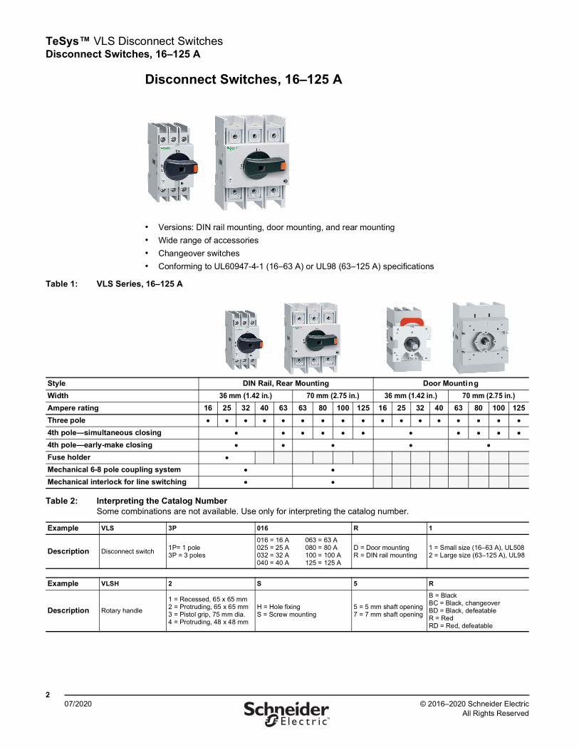
Disconnect Switches, 16–125 A
• Versions: DIN rail mounting, door mounting, and rear mounting• Wide range of accessories • Changeover switches• Conforming to UL60947-4-1 (16–63 A) or UL98 (63–125 A) specifications
Table 1: VLS Series, 16–125 A
Style DIN Rail, Rear Mounting Door Mounting Width 36 mm (1.42 in.) 70 mm (2.75 in.) 36 mm (1.42 in.) 70 mm (2.75 in.)Ampere rating 16 25 32 40 63 63 80 100 125 16 25 32 40 63 80 100 125Three pole ● ● ● ● ● ● ● ● ● ● ● ● ● ● ● ● ●
4th pole—simultaneous closing ● ● ● ● ● ● ● ● ● ● ●
4th pole—early-make closing ● ● ● ● ●
Fuse holder ●
Mechanical 6-8 pole coupling system ● ●
Mechanical interlock for line switching ● ●
Table 2: Interpreting the Catalog Number Some combinations are not available. Use only for interpreting the catalog number.
Example VLS 3P 016 R 1
Description Disconnect switch 1P= 1 pole 3P = 3 poles
016 = 16 A 025 = 25 A 032 = 32 A 040 = 40 A
063 = 63 A 080 = 80 A 100 = 100 A 125 = 125 A
D = Door mounting R = DIN rail mounting
1 = Small size (16–63 A), UL508 2 = Large size (63–125 A), UL98
Example VLSH 2 S 5 R
Description Rotary handle
1 = Recessed, 65 x 65 mm 2 = Protruding, 65 x 65 mm 3 = Pistol grip, 75 mm dia. 4 = Protruding, 48 x 48 mm
H = Hole fixing S = Screw mounting
5 = 5 mm shaft opening 7 = 7 mm shaft opening
B = Black BC = Black, changeover BD = Black, defeatable R = Red RD = Red, defeatable
TeSys™ VLS Disconnect SwitchesProduct Overview
307/2020© 2016–2020 Schneider Electric
All Rights Reserved™
Product Overview
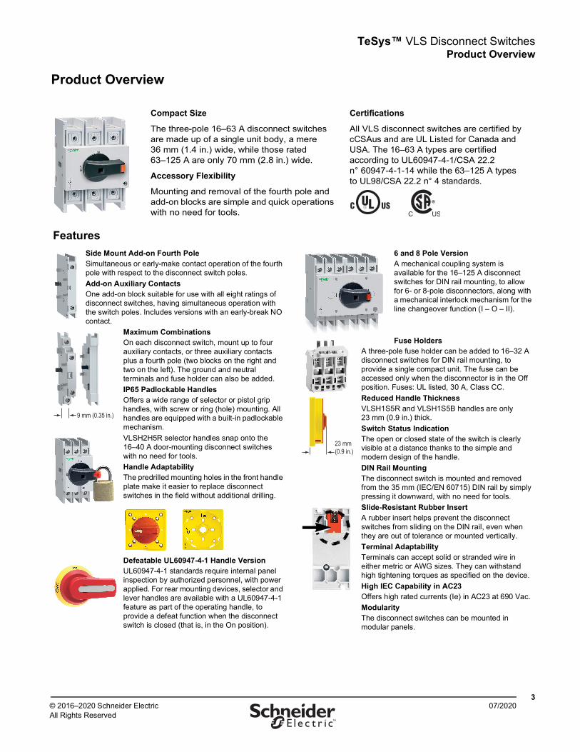
Compact Size
The three-pole 16–63 A disconnect switches are made up of a single unit body, a mere 36 mm (1.4 in.) wide, while those rated 63–125 A are only 70 mm (2.8 in.) wide.
Accessory Flexibility
Mounting and removal of the fourth pole and add-on blocks are simple and quick operations with no need for tools.
Certifications
All VLS disconnect switches are certified by cCSAus and are UL Listed for Canada and USA. The 16–63 A types are certified according to UL60947-4-1/CSA 22.2 n° 60947-4-1-14 while the 63–125 A types to UL98/CSA 22.2 n° 4 standards.
FeaturesSide Mount Add-on Fourth PoleSimultaneous or early-make contact operation of the fourth pole with respect to the disconnect switch poles.Add-on Auxiliary ContactsOne add-on block suitable for use with all eight ratings of disconnect switches, having simultaneous operation with the switch poles. Includes versions with an early-break NO contact.
Maximum CombinationsOn each disconnect switch, mount up to four auxiliary contacts, or three auxiliary contacts plus a fourth pole (two blocks on the right and two on the left). The ground and neutral terminals and fuse holder can also be added.IP65 Padlockable HandlesOffers a wide range of selector or pistol grip handles, with screw or ring (hole) mounting. All handles are equipped with a built-in padlockable mechanism.VLSH2H5R selector handles snap onto the 16–40 A door-mounting disconnect switches with no need for tools.Handle AdaptabilityThe predrilled mounting holes in the front handle plate make it easier to replace disconnect switches in the field without additional drilling.
Defeatable UL60947-4-1 Handle VersionUL60947-4-1 standards require internal panel inspection by authorized personnel, with power applied. For rear mounting devices, selector and lever handles are available with a UL60947-4-1 feature as part of the operating handle, to provide a defeat function when the disconnect switch is closed (that is, in the On position).
6 and 8 Pole VersionA mechanical coupling system is available for the 16–125 A disconnect switches for DIN rail mounting, to allow for 6- or 8-pole disconnectors, along with a mechanical interlock mechanism for the line changeover function (I – O – II).
Fuse HoldersA three-pole fuse holder can be added to 16–32 A disconnect switches for DIN rail mounting, to provide a single compact unit. The fuse can be accessed only when the disconnector is in the Off position. Fuses: UL listed, 30 A, Class CC.Reduced Handle ThicknessVLSH1S5R and VLSH1S5B handles are only 23 mm (0.9 in.) thick.Switch Status IndicationThe open or closed state of the switch is clearly visible at a distance thanks to the simple and modern design of the handle.DIN Rail MountingThe disconnect switch is mounted and removed from the 35 mm (IEC/EN 60715) DIN rail by simply pressing it downward, with no need for tools.Slide-Resistant Rubber Insert A rubber insert helps prevent the disconnect switches from sliding on the DIN rail, even when they are out of tolerance or mounted vertically.Terminal AdaptabilityTerminals can accept solid or stranded wire in either metric or AWG sizes. They can withstand high tightening torques as specified on the device.High IEC Capability in AC23Offers high rated currents (Ie) in AC23 at 690 Vac.ModularityThe disconnect switches can be mounted in modular panels.
9 mm (0.35 in.)
23 mm (0.9 in.)
TeSys™ VLS Disconnect SwitchesThree-Pole Disconnect Switches
407/2020 © 2016–2020 Schneider Electric
All Rights Reserved™
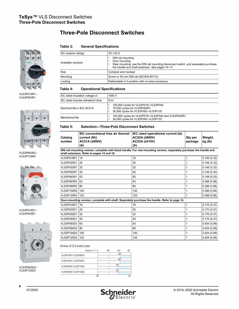
Three-Pole Disconnect Switches
Table 3: General Specifications
IEC ampere ratings 16–125 A
Available versions
• DIN rail mounting• Door mounting• Rear mounting: use the DIN rail mounting disconnect switch, and separately purchase
the handle and shaft extension. See pages 14–17.
Size Compact and modular
Mounting Screw or 35 mm DIN rail (IEC/EN 60715)
Locking Padlockable in 0 position with no extra accessory
Table 4: Operational Specifications
IEC rated insulation voltage Ui 1000 V
IEC rated impulse withstand Uimp 8 kV
Electrical life in IEC AC21A• 100,000 cycles for VLS3P016–VLS3P040• 15,000 cycles for VLS3P063R1• 30,000 cycles for VLS3P063–VLS3P125
Mechanical life • 100,000 cycles for VLS3P016–VLS3P040 and VLS3P063R1• 30,000 cycles for VLS3P063–VLS3P125
Table 5: Selection—Three-Pole Disconnect Switches
Catalog number
IEC conventional free air thermal current (Ith)AC21A (≤690V)(A)
IEC rated operational current (Ie)AC22A (≤690V) AC23A (≤415V)(A)
Qty per package
Weight, kg (lb)
DIN rail mounting version, complete with black handle. For rear-mounting version, separately purchase the handle and shaft extension. Refer to pages 14 and 16.VLS3P016R1 16 16 1 0.146 (0.32)
VLS3P025R1 25 25 1 0.146 (0.32)
VLS3P032R1 32 32 1 0.146 (0.32)
VLS3P040R1 40 40 1 0.146 (0.32)
VLS3P063R1 63 45 1 0.148 (0.33)
VLS3P063R2 63 63 1 0.388 (0.86)
VLS3P080R2 80 80 1 0.388 (0.86)
VLS3P100R2 100 100 1 0.388 (0.86)
VLS3P125R2 125 125 1 0.388 (0.86)
Door-mounting version, complete with shaft. Separately purchase the handle. Refer to page 14.VLS3P016D1 16 16 1 0.170 (0.37)
VLS3P025D1 25 25 1 0.170 (0.37)
VLS3P032D1 32 32 1 0.170 (0.37)
VLS3P040D1 40 40 1 0.170 (0.37)
VLS3P063D2 63 63 1 0.404 (0.89)
VLS3P080D2 80 80 1 0.404 (0.89)
VLS3P100D2 100 100 1 0.404 (0.89)
VLS3P125D2 125 125 1 0.404 (0.89)
VLS3P016R1–VLS3P063R1
VLS3P063R2–VLS3P125R2
VLS3P016D1–VLS3P040D1
VLS3P063D2–VLS3P125D2
Strokes of VLS switch poles
Travel 0 1 0° 30° 60° 90°60°
60°
55°
55°
Off On
VLS3P016R1–VLS3P063R1
VLS3P016D1–VLS3P040D1
VLS3P063R2–VLS3P125R2
VLS3P063D2–VLS3P125D2
TeSys™ VLS Disconnect Switches Three-Pole Disconnect Switches
507/2020© 2016–2020 Schneider Electric
All Rights Reserved™
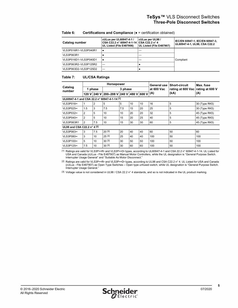
Table 6: Certifications and Compliance (● = certification obtained)
Catalog numbercULus per UL60947-4-1 / CSA C22.2 n° 60947-4-1-14 UL Listed (File E487906)
cULus per UL98 / CSA C22.2 n° 4 UL Listed (File E487907)
IEC/EN 60947-1, IEC/EN 60947-3, UL60947-4-1, UL98, CSA C22.2
VLS3P016R1–VLS3P040R1 ● —
Compliant
VLS3P063R1 ● —
VLS3P016D1–VLS3P040D1 ● —
VLS3P063R2–VLS3P125R2 — ●
VLS3P063D2–VLS3P125D2 — ●
Table 7: UL/CSA Ratings
Catalog number
Horsepower General use at 600 Vac(A)
Short-circuit rating at 600 Vac(kA)
Max. fuse rating at 600 V(A)
1 phase 3 phase120 V 240 V 200–208 V 240 V 480 V 600 V
UL60947-4-1 and CSA 22.2 n° 60947-4-1-14 [1]
[1] Ratings are valid for VLS3P•••R• and VLS3P•••D• types, according to UL60947-4-1 and CSA 22.2 n° 60947-4-1-14. UL Listed for USA and Canada (cULus - File E487907) as Manual Motor Controllers, while the UL designation is “General Purpose Switch. Interrupter Usage General” and “Suitable As Motor Disconnect.”
VLS3P016•• 1 2 5 5 10 10 16 5 30 (Type RK5)
VLS3P025•• 1.5 3 7.5 7.5 15 20 25 5 30 (Type RK5)
VLS3P032•• 2 5 10 10 20 20 32 5 45 (Type RK5)
VLS3P040•• 2 5 10 15 20 25 40 5 45 (Type RK5)
VLS3P063R1 2 7.5 10 15 30 30 60 5 45 (Type RK5)
UL98 and CSA C22.2 n° 4 [2]
[2] Ratings are valid for VLS3P•••R• and VLS3P•••D• types, according to UL98 and CSA C22.2 n° 4. UL Listed for USA and Canada (cULus - File E487907) as Open Type Switches – Open type unfused switch, while UL designation is “General Purpose Switch. Interrupter Usage General.”
VLS3P063•• 3 7.5 20 [3]
[3] Voltage value is not considered in UL98 / CSA 22.2 n° 4 standards, and so is not indicated in the UL product marking.
20 40 40 60 50 60
VLS3P080•• 3 10 25 [3] 25 40 40 100 50 100
VLS3P100•• 5 10 30 [3] 30 50 50 100 50 100
VLS3P125•• 7.5 10 30 [3] 30 60 60 100 50 100

TeSys™ VLS Disconnect SwitchesFourth Pole Add-on
607/2020 © 2016–2020 Schneider Electric
All Rights Reserved™
Fourth Pole Add-on
Table 8: General Specifications—Fourth Pole Add-on
IEC ampere ratings 16–125 A
Available versions
• DIN rail mounting• Door mounting• Simultaneous closing with switch poles• Early-make closing with respect to switch poles
Size Compact and modular
Table 9: Operational Specifications—Fourth Pole Add-on
IEC rated insulation voltage, Ui 1000 V
IEC rated impulse withstand, Uimp 8 kV
Electrical life in IEC AC21A• 100,000 cycles for VLS1P040R1S/D1S and VLS1P040R1E/D1E• 15,000 cycles for VLS1P063R1S and VLS1P063R1E• 30,000 cycles for VLS1P063R2S/D2S and VLS1P125R2E/C
Mechanical life• 100,000 cycles for VLS1P040R1S/D1S, VLS1P040R1E/D1E, VLS1P063R1S, and
VLS1P063R1E• 30,000 cycles for VLS1P063R2S/D2S – VLS1P125R2S/D2S and VLS1P125R2E/D2E
Table 10: Selection—Fourth Pole Add-on
Catalog number
IEC conventional free air thermal current Ith AC21A [1] (s690V)(A)
[1] See page 5 for UL/CSA ratings, which are the same as the ratings for the corresponding switch types.
IEC rated operational current Ie [1] AC22A (s690V), AC23A (s415V)(A)
Qty per package
Weight kg (lb)
Simultaneous closing operation with respect to switch polesDIN Rail Mounting (VLS3P•••R•)VLS1P040R1S [2]
[2] For VLS3P016R1–040R1 only.
40 40 1 0.045 (0.10)
VLS1P063R1S [3]
[3] For VLS3P063R1 only.
63 45 1 0.045 (0.10)
VLS1P063R2S 63 63 1 0.126 (0.28)
VLS1P080R2S 80 80 1 0.126 (0.28)
VLS1P100R2S 100 100 1 0.126 (0.28)
VLS1P125R2S 125 125 1 0.126 (0.28)
Door Mounting (VLS3P•••D•)VLS1P040D1S [4]
[4] For VLS3P016D1–040D1 only.
40 40 1 0.045 (0.10)
VLS1P063D2S 63 63 1 0.128 (0.28)
VLS1P080D2S 80 80 1 0.128 (0.28)
VLS1P100D2S 100 100 1 0.128 (0.28)
VLS1P125D2S 125 125 1 0.128 (0.28)
Early-make closing operation with respect to switch polesDIN Rail Mounting (VLS3P•••R•)VLS1P040R1E [2] 40 40 1 0.046 (0.10)
VLS1P063R1E [4] 63 45 1 0.046 (0.10)
VLS1P125R2E [5]
[5] For VLS3P063R2–125R2 only.
125 125 1 0.116 (0.26)
Door Mounting (VLS3P•••D•)VLS1P040D1E [4] 40 40 1 0.046 (0.10)
VLS1P125D2E [6]
[6] For VLS3P063D2–125D2 only.
125 125 1 0.128 (0.28)
VLS1P•••R•SVLS1P•••R•E
VLS1P040D1SVLS1P040D1E
TeSys™ VLS Disconnect Switches Fourth Pole Add-on
707/2020© 2016–2020 Schneider Electric
All Rights Reserved™
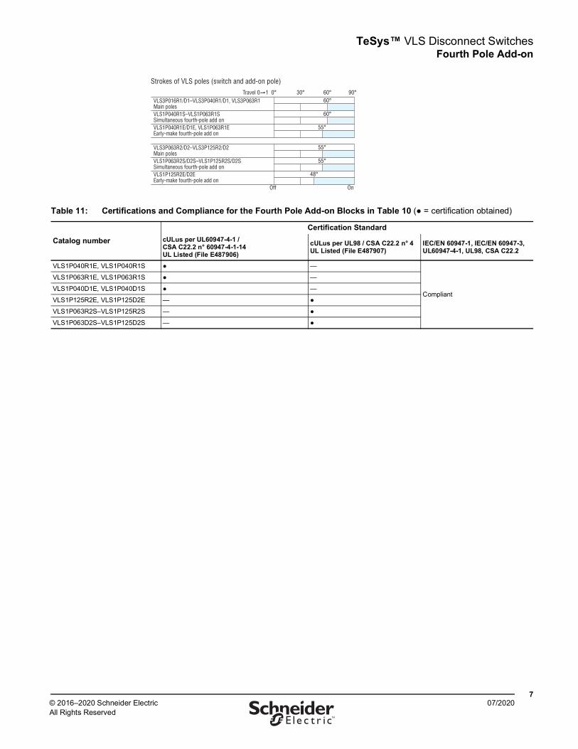
Strokes of VLS poles (switch and add-on pole)Travel 0 1 0° 30° 60° 90°
60°
60°
55°
55°
55°
48°
Off On
VLS3P016R1/D1–VLS3P040R1/D1, VLS3P063R1Main polesVLS1P040R1S–VLS1P063R1SSimultaneous fourth-pole add on VLS1P040R1E/D1E, VLS1P063R1EEarly-make fourth-pole add on
VLS3P063R2/D2–VLS3P125R2/D2Main polesVLS1P063R2S/D2S–VLS1P125R2S/D2SSimultaneous fourth-pole add onVLS1P125R2E/D2EEarly-make fourth-pole add on
Table 11: Certifications and Compliance for the Fourth Pole Add-on Blocks in Table 10 (● = certification obtained)
Catalog numberCertification Standard
cULus per UL60947-4-1 / CSA C22.2 n° 60947-4-1-14 UL Listed (File E487906)
cULus per UL98 / CSA C22.2 n° 4 UL Listed (File E487907)
IEC/EN 60947-1, IEC/EN 60947-3, UL60947-4-1, UL98, CSA C22.2
VLS1P040R1E, VLS1P040R1S ● —
Compliant
VLS1P063R1E, VLS1P063R1S ● —
VLS1P040D1E, VLS1P040D1S ● —
VLS1P125R2E, VLS1P125D2E — ●
VLS1P063R2S–VLS1P125R2S — ●
VLS1P063D2S–VLS1P125D2S — ●
TeSys™ VLS Disconnect SwitchesSequence and Maximum Combination of Add-on Blocks
807/2020 © 2016–2020 Schneider Electric
All Rights Reserved™
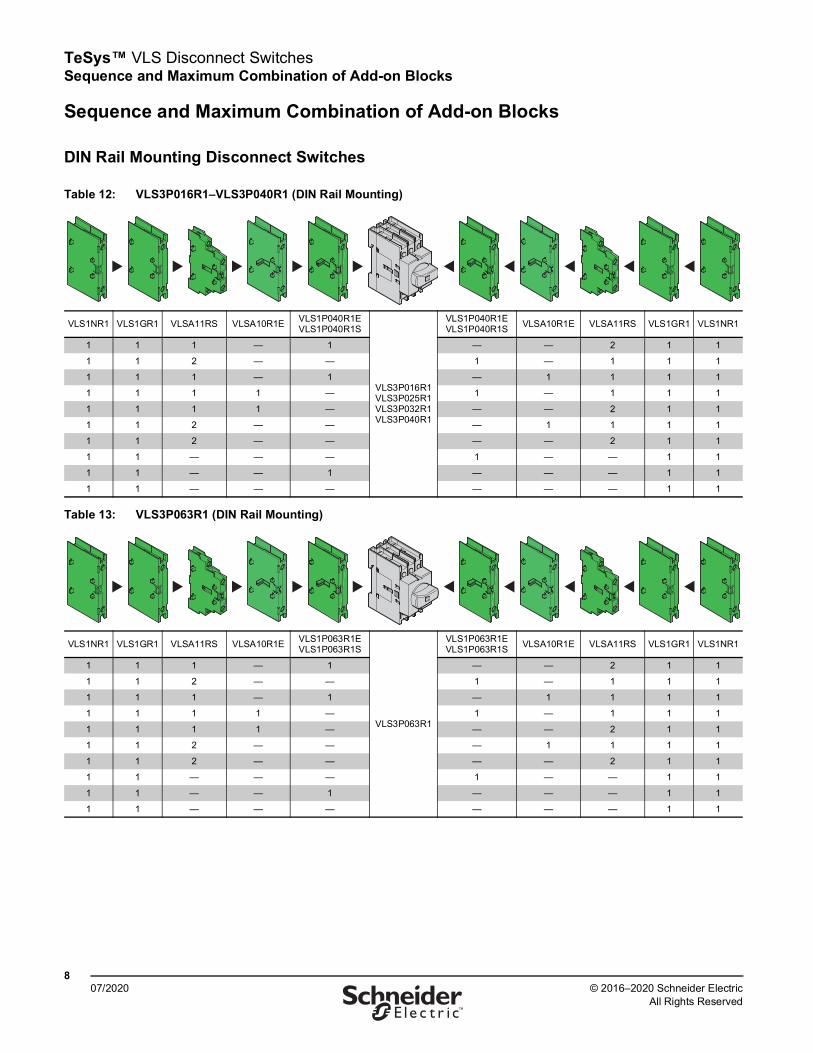
Sequence and Maximum Combination of Add-on Blocks
DIN Rail Mounting Disconnect Switches
Table 12: VLS3P016R1–VLS3P040R1 (DIN Rail Mounting)
VLS1NR1 VLS1GR1 VLSA11RS VLSA10R1E VLS1P040R1EVLS1P040R1S
VLS3P016R1VLS3P025R1VLS3P032R1VLS3P040R1
VLS1P040R1EVLS1P040R1S VLSA10R1E VLSA11RS VLS1GR1 VLS1NR1
1 1 1 — 1 — — 2 1 1
1 1 2 — — 1 — 1 1 1
1 1 1 — 1 — 1 1 1 1
1 1 1 1 — 1 — 1 1 1
1 1 1 1 — — — 2 1 1
1 1 2 — — — 1 1 1 1
1 1 2 — — — — 2 1 1
1 1 — — — 1 — — 1 1
1 1 — — 1 — — — 1 1
1 1 — — — — — — 1 1
Table 13: VLS3P063R1 (DIN Rail Mounting)
VLS1NR1 VLS1GR1 VLSA11RS VLSA10R1E VLS1P063R1EVLS1P063R1S
VLS3P063R1
VLS1P063R1EVLS1P063R1S VLSA10R1E VLSA11RS VLS1GR1 VLS1NR1
1 1 1 — 1 — — 2 1 1
1 1 2 — — 1 — 1 1 1
1 1 1 — 1 — 1 1 1 1
1 1 1 1 — 1 — 1 1 1
1 1 1 1 — — — 2 1 1
1 1 2 — — — 1 1 1 1
1 1 2 — — — — 2 1 1
1 1 — — — 1 — — 1 1
1 1 — — 1 — — — 1 1
1 1 — — — — — — 1 1
TeSys™ VLS Disconnect Switches Sequence and Maximum Combination of Add-on Blocks
907/2020© 2016–2020 Schneider Electric
All Rights Reserved™
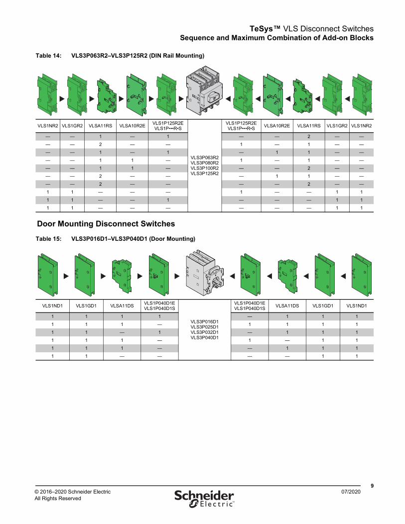
Table 14: VLS3P063R2–VLS3P125R2 (DIN Rail Mounting)
VLS1NR2 VLS1GR2 VLSA11RS VLSA10R2E VLS1P125R2EVLS1P•••R•S
VLS3P063R2 VLS3P080R2 VLS3P100R2 VLS3P125R2
VLS1P125R2EVLS1P•••R•S VLSA10R2E VLSA11RS VLS1GR2 VLS1NR2
— — 1 — 1 — — 2 — —
— — 2 — — 1 — 1 — —
— — 1 — 1 — 1 1 — —
— — 1 1 — 1 — 1 — —
— — 1 1 — — — 2 — —
— — 2 — — — 1 1 — —
— — 2 — — — — 2 — —
1 1 — — — 1 — — 1 1
1 1 — — 1 — — — 1 1
1 1 — — — — — — 1 1
Door Mounting Disconnect Switches
Table 15: VLS3P016D1–VLS3P040D1 (Door Mounting)
VLS1ND1 VLS1GD1 VLSA11DS VLS1P040D1EVLS1P040D1S
VLS3P016D1 VLS3P025D1 VLS3P032D1 VLS3P040D1
VLS1P040D1EVLS1P040D1S VLSA11DS VLS1GD1 VLS1ND1
1 1 1 1 — 1 1 1
1 1 1 — 1 1 1 1
1 1 — 1 — 1 1 1
1 1 1 — 1 — 1 1
1 1 1 — — 1 1 1
1 1 — — — — 1 1

TeSys™ VLS Disconnect SwitchesSequence and Maximum Combination of Add-on Blocks
1007/2020 © 2016–2020 Schneider Electric
All Rights Reserved™
Table 16: VLS3P063D2–VLS3P125D2 (Door Mounting)
VLS1ND2 VLS1GD2 VLSA11DS VLS1P125D2EVLS1P125D2S
VLS3P063D2 VLS3P080D2 VLS3P100D2 VLS3P125D2
VLS1P125D2EVLS1P125D2S VLSA11DS VLS1GD2 VLS1ND2
— — 1 1 — 1 — —
— — 1 — 1 1 — —
1 1 — 1 — 1 — —
— — 1 — 1 — 1 1
— — 1 — — 1 — —
1 1 — — — — 1 1
Mechanical Coupling and Mechanical Interlock for Line Changeover
Table 17: VLS3P016R1–VLS3P040R1, VLS8C1–VLS8M1 (Rear Mounting)
VLS1NR1 VLS1GR1 VLSA11RS VLSA10R1E VLS1P040R1EVLS1P040R1S VLS8C1–VLS8M1 VLS1P040R1E
VLS1P040R1S VLSA10R1E VLSA11RS VLS1GR1 VLS1NR1
1 1 1 — 1
VLS3P016R1 + VLS3P016R1
VLS3P025R1 + VLS3P025R1
VLS3P032R1 + VLS3P032R1
VLS3P040R1 + VLS3P040R1
1 — 1 1 1
1 1 1 — 1 — — 2 1 1
1 1 2 — — 1 — 1 1 1
1 1 1 — 1 — 1 1 1 1
1 1 1 1 — 1 — 1 1 1
1 1 1 1 — — — 2 1 1
1 1 2 — — — 1 1 1 1
1 1 2 — — — — 2 1 1
1 1 — — 1 1 — — 1 1
1 1 — — — — — — 1 1
TeSys™ VLS Disconnect Switches Sequence and Maximum Combination of Add-on Blocks
1107/2020© 2016–2020 Schneider Electric
All Rights Reserved™
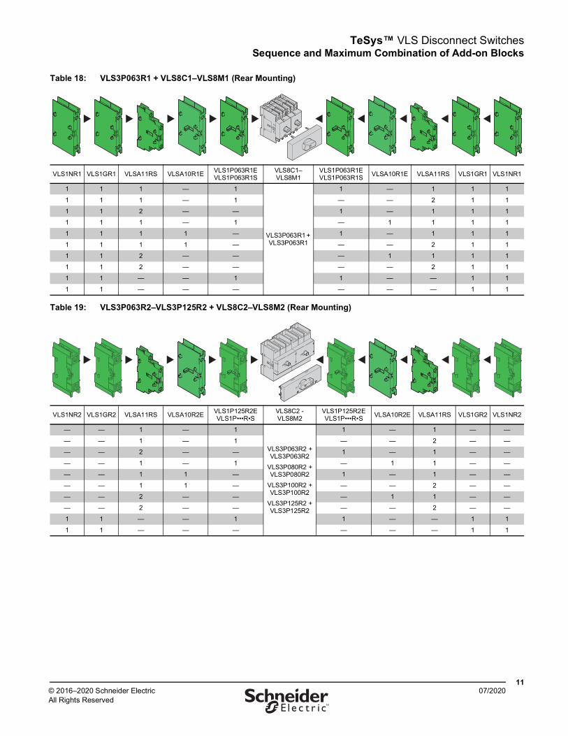
Table 18: VLS3P063R1 + VLS8C1–VLS8M1 (Rear Mounting)
VLS1NR1 VLS1GR1 VLSA11RS VLSA10R1E VLS1P063R1EVLS1P063R1S
VLS8C1–VLS8M1
VLS1P063R1EVLS1P063R1S VLSA10R1E VLSA11RS VLS1GR1 VLS1NR1
1 1 1 — 1
VLS3P063R1 + VLS3P063R1
1 — 1 1 1
1 1 1 — 1 — — 2 1 1
1 1 2 — — 1 — 1 1 1
1 1 1 — 1 — 1 1 1 1
1 1 1 1 — 1 — 1 1 1
1 1 1 1 — — — 2 1 1
1 1 2 — — — 1 1 1 1
1 1 2 — — — — 2 1 1
1 1 — — 1 1 — — 1 1
1 1 — — — — — — 1 1
Table 19: VLS3P063R2–VLS3P125R2 + VLS8C2–VLS8M2 (Rear Mounting)
VLS1NR2 VLS1GR2 VLSA11RS VLSA10R2E VLS1P125R2EVLS1P•••R•S
VLS8C2 - VLS8M2
VLS1P125R2EVLS1P•••R•S VLSA10R2E VLSA11RS VLS1GR2 VLS1NR2
— — 1 — 1
VLS3P063R2 + VLS3P063R2
VLS3P080R2 + VLS3P080R2
VLS3P100R2 + VLS3P100R2
VLS3P125R2 + VLS3P125R2
1 — 1 — —
— — 1 — 1 — — 2 — —
— — 2 — — 1 — 1 — —
— — 1 — 1 — 1 1 — —
— — 1 1 — 1 — 1 — —
— — 1 1 — — — 2 — —
— — 2 — — — 1 1 — —
— — 2 — — — — 2 — —
1 1 — — 1 1 — — 1 1
1 1 — — — — — — 1 1
TeSys™ VLS Disconnect SwitchesAccessories
1207/2020 © 2016–2020 Schneider Electric
All Rights Reserved™
Accessories
Add-on Blocks
Table 20: Operational Specifications
Auxiliary contactsIEC conventional free air thermal current (Ith) 10 A
UL/CSA and IEC/EN 60947-5-1 designation A600-Q600
Tightening torque 0.8 N•m (7.1 lb-in.)
Other devices
Tightening torque
VLS1NR1/D1, VLS1GR1/D1 terminals 1.8–2 N•m (16–18 lb-in)
VLS1NR2/D2, VLS1GR2/D2 terminals 5–6 N•m (45–54 lb-in)
VLS8C1/C2, VLS8M1/M2 mounting: 0.5 N•m (4.4 lb-in) extension with handle: 0.8 N•m (7.1 lb-in)
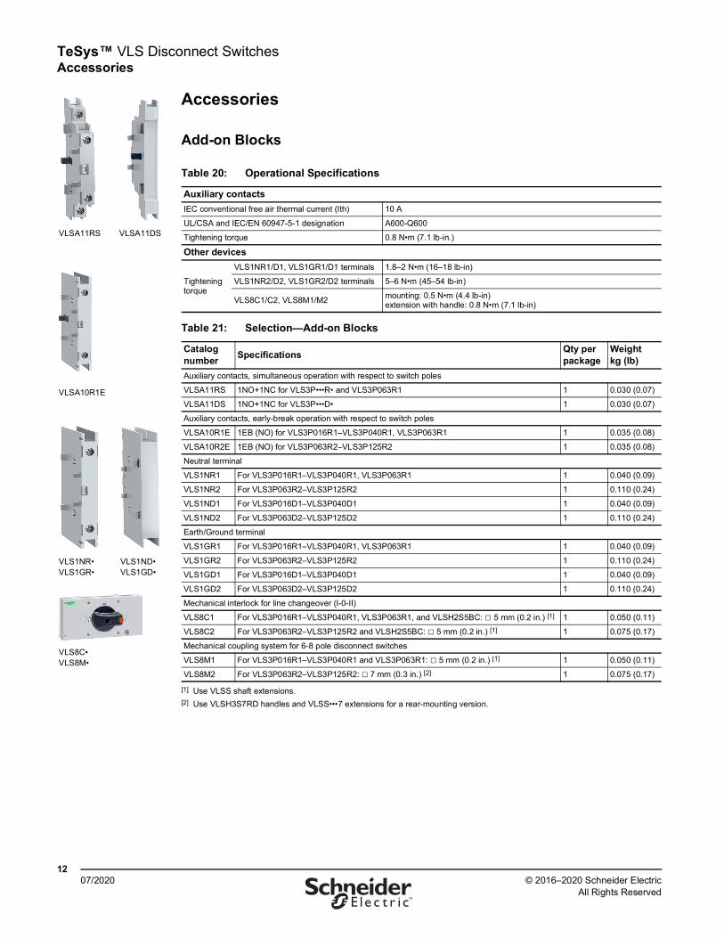
Table 21: Selection—Add-on Blocks
Catalog number Specifications Qty per
packageWeight kg (lb)
Auxiliary contacts, simultaneous operation with respect to switch poles
VLSA11RS 1NO+1NC for VLS3P•••R• and VLS3P063R1 1 0.030 (0.07)
VLSA11DS 1NO+1NC for VLS3P•••D• 1 0.030 (0.07)
Auxiliary contacts, early-break operation with respect to switch poles
VLSA10R1E 1EB (NO) for VLS3P016R1–VLS3P040R1, VLS3P063R1 1 0.035 (0.08)
VLSA10R2E 1EB (NO) for VLS3P063R2–VLS3P125R2 1 0.035 (0.08)
Neutral terminal
VLS1NR1 For VLS3P016R1–VLS3P040R1, VLS3P063R1 1 0.040 (0.09)
VLS1NR2 For VLS3P063R2–VLS3P125R2 1 0.110 (0.24)
VLS1ND1 For VLS3P016D1–VLS3P040D1 1 0.040 (0.09)
VLS1ND2 For VLS3P063D2–VLS3P125D2 1 0.110 (0.24)
Earth/Ground terminal
VLS1GR1 For VLS3P016R1–VLS3P040R1, VLS3P063R1 1 0.040 (0.09)
VLS1GR2 For VLS3P063R2–VLS3P125R2 1 0.110 (0.24)
VLS1GD1 For VLS3P016D1–VLS3P040D1 1 0.040 (0.09)
VLS1GD2 For VLS3P063D2–VLS3P125D2 1 0.110 (0.24)
Mechanical interlock for line changeover (I-0-II)
VLS8C1 For VLS3P016R1–VLS3P040R1, VLS3P063R1, and VLSH2S5BC: □ 5 mm (0.2 in.) [1]
[1] Use VLSS shaft extensions.
1 0.050 (0.11)
VLS8C2 For VLS3P063R2–VLS3P125R2 and VLSH2S5BC: □ 5 mm (0.2 in.) [1] 1 0.075 (0.17)
Mechanical coupling system for 6-8 pole disconnect switches
VLS8M1 For VLS3P016R1–VLS3P040R1 and VLS3P063R1: □ 5 mm (0.2 in.) [1] 1 0.050 (0.11)
VLS8M2 For VLS3P063R2–VLS3P125R2: □ 7 mm (0.3 in.) [2]
[2] Use VLSH3S7RD handles and VLSS•••7 extensions for a rear-mounting version.
1 0.075 (0.17)
VLSA11RS
VLS8C•VLS8M•
VLSA11DS
VLSA10R1E
VLS1NR•VLS1GR•
VLS1ND•VLS1GD•

TeSys™ VLS Disconnect Switches Accessories
1307/2020© 2016–2020 Schneider Electric
All Rights Reserved™
Figure 1: Transformation of the DIN rail mounting version into the rear mounting version
Strokes of VLS poles (switch with auxiliary contact blocks)Travel 0→ 1 0° 30° 60° 90°
60°
60°
40°Travel 0→ 1 60°
Travel 1→ 0 70°
55°
45°
25°Travel 0→ 1 55°
Travel 1→ 0 65°
Off On
VLS3P016R1/D1, VLS3P040R1/D1, VLS3P063R1 Main polesVLSA11RS/DSAuxiliary contacts (1 NO + 1 NC) NO
NC
VLSA10R1EAuxiliary contact(1EB – NO early break)
VLS3P063R2/D2…VLS3P125R2/D2Main polesVLSA11RS/DSAuxiliary contacts (1 NO + 1 NC) NO
NC
VLSA10R2EAuxiliary contact (1EB – NO early break)
VLSH3..B
65
0
III
VLS3P…R1+VLS8C…1/+VLS8M…1
VLSS…5
VLS3P...R2+VLS8C…2/+VLS8M…2
Table 22: Certifications and Compliance (● = certification obtained)
Catalog numbercULus per UL60947-4-1 / CSA C22.2 n° 60947-4-1-14 UL Listed (File E487906)
cULus per UL98 / CSA C22.2 n° 4 UL Listed (File E487907)
VLSA11RS/DSUL Listed, cULus File E478582CSA C22.2 n° 14-10
—
VLSA10R1E —
VLSA10R2E —
VLS1NR1/D1 ● —
VLS1NR2/D2 — ●VLS1GR1/D1 ● —
VLS1GR2/D2 — ●VLS8C1/M1 ● —
VLS8C2/M2 — ●VLSH1S5R/B ● ●VLSH2S5R/B ● ●VLSH2H5R/B ● ●VLSH4S5R/B ● ●VLSH2S5RD/BD ● ●VLSH3S7RD/BD — ●VLSH2H5BC ● ●VLSHA7 — ●Compliant with standards: IEC/EN 60947-1, IEC/EN 60947-3, IEC/EN 60947-5-1, UL60947-4-1, UL98, CSA C22.2.NOTE: VLSH1S5R/B and VLSH3S7NRD/BD are UL/CSA Type 1, 12, 3R, 4, and 4X outdoor use with all VLS switch models. VLSH2S5R/B, VLSH2H5R/B, VLSH2H5RD/BD and VLSH2S5BC are UL/CSA Type 1, 12, 3R, 4, and 4X outdoor use with VLS3P016R1/D1–VLS3P040R1/D1 and VLS3P063R1 models, otherwise Type 1 only.
TeSys™ VLS Disconnect SwitchesAccessories
1407/2020 © 2016–2020 Schneider Electric
All Rights Reserved™
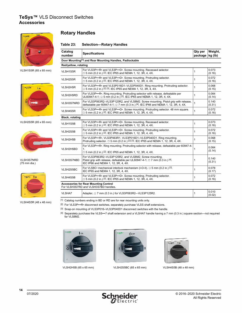
Rotary Handles
Table 23: Selection—Rotary Handles
Catalog number Specifications Qty per
packageWeight, kg (lb)
Door Mounting[1] and Rear Mounting Handles, Padlockable
[1] Catalog numbers ending in BD or RD are for rear mounting units only.
Red/yellow, rotating
VLSH1S5R For VLS3P•••R• and VLS3P•••D•. Screw mounting. Recessed selector. □ 5 mm (0.2 in.) [2]. IEC IP65 and NEMA 1, 12, 3R, 4, 4X.
[2] For VLS3P•••R• disconnect switches, separately purchase VLSS shaft extensions.
1 0.073 (0.16)
VLSH2S5R For VLS3P•••R• and VLS3P•••D•. Screw mounting. Protruding selector. □ 5 mm (0.2 in.) [2]. IEC IP65 and NEMA 1, 12, 3R, 4, 4X. 1 0.072
(0.16)
VLSH2H5R For VLS3P•••R• and VLS3P016D1–VLS3P040D1. Ring mounting. Protruding selector. □ 5 mm (0.2 in.) [2] [3]. IEC IP65 and NEMA 1, 12, 3R, 4, 4X.
[3] Snap-on mounting of VLS3P016–VLS3P040D1 disconnect switches with the handle.
1 0.068 (0.15)
VLSH2H5RD For VLS3P•••R•. Ring mounting. Protruding selector with release, defeatable per UL60947-4-1; □ 5 mm (0.2 in.) [2]. IEC IP65 and NEMA 1, 12, 3R, 4, 4X. 1 0.064
(0.14)
VLSH3S7NRD For VLS3P063R2–VLS3P125R2, and VLS8M2. Screw mounting. Pistol grip with release, defeatable per 60947-4-1; □ 7 mm (0.3 in.) [4]. IEC IP66 and NEMA 1, 12, 3R, 4, 4X.
[4] Separately purchase the VLSS•••7 shaft extension and a VLSHA7 handle having a 7 mm (0.3 in.) square section—not required for VLS8M2.
1 0.140 (0.31)
VLSH4S5R For VLS3P•••R• and VLS3P•••D•. Screw mounting. Protruding selector. 48 mm square. □ 5 mm (0.2 in.) [2]. IEC IP65 and NEMA 1, 12, 3R, 4, 4X. 1 0.072
(0.16)
Black, rotating
VLSH1S5B For VLS3P•••R• and VLS3P•••D•. Screw mounting. Recessed selector. □ 5 mm (0.2 in.) [2]. IEC IP65 and NEMA 1, 12, 3R, 4, 4X. 1 0.073
(0.16)
VLSH2S5B For VLS3P•••R• and VLS3P•••D•. Screw mounting. Protruding selector. □ 5 mm (0.2 in.) [2]. IEC IP65 and NEMA 1, 12, 3R, 4, 4X. 1 0.072
(0.16)
VLSH2H5B For VLS3P•••R•, VLS3P063R1, VLS3P016D1–VLS3P040D1. Ring mounting. Protruding selector. □ 5 mm (0.2 in.) [2] [3]. IEC IP65 and NEMA 1, 12, 3R, 4, 4X. 1 0.068
(0.15)
VLSH2H5BDFor VLS3P•••R•. Ring mounting. Protruding selector with release, defeatable per 60947-4-1. □ 5 mm (0.2 in.) [2]. IEC IP65 and NEMA 1, 12, 3R, 4, 4X.
1 0.064 (0.14)
VLSH3S7NBDFor VLS3P063R2–VLS3P125R2, and VLS8M2. Screw mounting. Pistol grip with release, defeatable per UL60947-4-1; □ 7 mm (0.3 in.) [4]. IEC IP66 and NEMA 1, 12, 3R, 4, 4X.
1 0.140 (0.31)
VLSH2S5BC For VLS8C• mechanical interlock mechanism (I-O-II). □ 5 mm (0.2 in.) [2]. IEC IP65 and NEMA 1, 12, 3R, 4, 4X. 1 0.078
(0.17)
VLSH4S5B For VLS3P•••R• and VLS3P•••D•. Screw mounting. Protruding selector. □ 5 mm (0.2 in.) [2]. IEC IP65 and NEMA 1, 12, 3R, 4, 4X. 1 0.072
(0.16)
Accessories for Rear Mounting Control For VLSH3S7RD and VLSH3S7BD handles.
VLSHA7 Adapter, □ 7 mm (0.3 in.) for VLS3P063R2-–VLS3P125R2. 1 0.010 (0.02)
VLSH1S5R (65 x 65 mm)
VLSH2S5R (65 x 65 mm)
VLSH3S7NRD (75 mm dia.)
VLSH4S5R (48 x 48 mm)
VLSH2H5B (65 x 65 mm) VLSH2S5BC (65 x 65 mm) VLSH4S5B (48 x 48 mm)
TeSys™ VLS Disconnect SwitchesAccessories
1507/2020© 2016–2020 Schneider Electric
All Rights Reserved™
Certifications and Compliance
See Table 22 on page 13 for details.
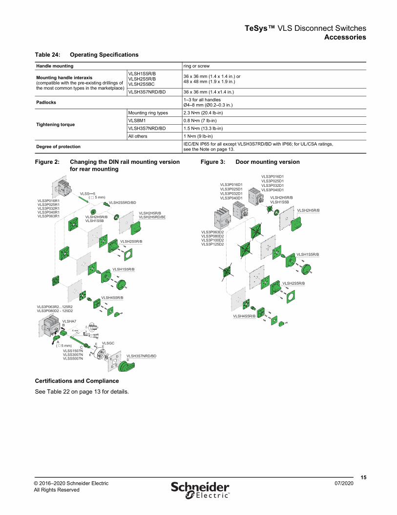
Table 24: Operating Specifications
Handle mounting ring or screw
Mounting handle interaxis (compatible with the pre-existing drillings of the most common types in the marketplace)
VLSH1S5R/B VLSH2S5R/B VLSH2S5BC
36 x 36 mm (1.4 x 1.4 in.) or 48 x 48 mm (1.9 x 1.9 in.)
VLSH3S7NRD/BD 36 x 36 mm (1.4 x1.4 in.)
Padlocks 1–3 for all handles Ø4–8 mm (Ø0.2–0.3 in.)
Tightening torque
Mounting ring types 2.3 N•m (20.4 lb-in)
VLS8M1 0.8 N•m (7 lb-in)
VLSH3S7NRD/BD 1.5 N•m (13.3 lb-in)
All others 1 N•m (9 lb-in)
Degree of protection IEC/EN IP65 for all except VLSH3S7RD/BD with IP66; for UL/CSA ratings, see the Note on page 13.
Figure 2: Changing the DIN rail mounting version for rear mounting
Figure 3: Door mounting version
VLSH2S5RD/BDVLS3P016R1VLS3P025R1VLS3P032R1VLS3P040R1VLS3P063R1
VLSH2H5R/BVLSH2H5RD/BD
VLSH1S5R/B
VLSH4S5R/B
VLSH2S5R/B
( 5 mm)VLSS•••5
VLSH2H5R/BVLSH1S5B
VLS3P063R2...125R2VLS3P080D2 - 125D2
VLSGC
VLSHA7
DD D
D
D
E
E
E
E
E
C
B
A( 5 mm)
VLSS1507NVLSS3007NVLSS5007N
VLSH3S7NRD/BD
X mm3
o3.5
o3.5
3
VLSH2H5R/B
VLS3P016D1VLS3P025D1VLS3P032D1VLS3P040D1
VLS3P016D1VLS3P025D1VLS3P032D1VLS3P040D1
VLS3P063D2VLS3P080D2VLS3P100D2VLS3P125D2
VLSH2S5R/B
VLSH4S5R/B
VLSH1S5R/B
VLSH2H5R/BVLSH1S5B
TeSys™ VLS Disconnect SwitchesAccessories
1607/2020 © 2016–2020 Schneider Electric
All Rights Reserved™
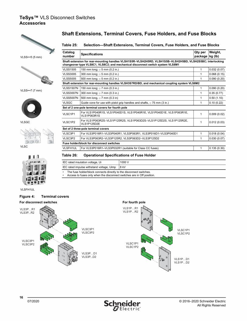
Shaft Extensions, Terminal Covers, Fuse Holders, and Fuse Blocks
Table 25: Selection—Shaft Extensions, Terminal Covers, Fuse Holders, and Fuse Blocks
Catalog number Specifications Qty per
packageWeight, kg (lb)
Shaft extension for rear-mounting handles VLSH1S5R–VLSH2H5RD, VLSH1S5B–VLSH2H5BD, VLSH2S5BC; interlocking changeover type VLS8C1, VLS8C2; and mechanical disconnect switch system VLS8M1VLSS1505 150 mm long; □ 5 mm (0.2 in.) 1 0.032 (0.07)VLSS3005 300 mm long; □ 5 mm (0.2 in.) 1 0.068 (0.15)VLSS5005 500 mm long; □ 5 mm (0.2 in.) 1 0.090 (0.20)Shaft extension for rear-mounting handles VLSH3S7RD/BD, and mechanical coupling system VLS8M2VLSS1507N 150 mm long; □ 7 mm (0.3 in.) 1 0.090 (0.20)
VLSS3007N 300 mm long; □ 7 mm (0.3 in.) 1 0.35 (0.77)
VLSS5007N 500 mm long, □ 7 mm (0.3 in) 1 0.50 (1.10)
VLSGC Guide cone for use with pistol grip handles and shafts, □ 75 mm (3 in.) 1 0.10 (0.22)
Set of 2 one-pole terminal covers for fourth pole
VLSC1P1 For VLS1P040R1S, VLS1P040D1S, VLS1P040R1E, VLS1P040D1E, VLS1P063R1E, VLS1P063R1S 1 0.009 (0.02)
VLSC1P2 For VLS1P063R2S–VLS1P125R2S, VLS1P063D2S–VLS1P125D2S, VLS1P125R2E, VLS1P125D2E 1 0.012 (0.03)
Set of 2 three-pole terminal coversVLSC3P1 For VLS3P016R1–VLS3P040R1, VLS3P063R1, VLS3P016D1–VLS3P040D1 1 0.018 (0.04)
VLSC3P2 For VLS3P063R2–VLS3P125R2, VLS3P063D2–VLS3P125D2 1 0.030 (0.07)
Fuse holder/block for disconnect switchesVLSFH1UL For VLS3P016R1–VLS3P032R1 (suitable for Class CC fuses) 1 0.135 (0.30)
Table 26: Operational Specifications of Fuse Holder
IEC rated insulation voltage, Ui 1000 V
IEC rated impulse withstand voltage, Uimp 8 kV
• The fuse holder/block connects directly to the disconnect switches.• Access to fuses only when the disconnect switches are in Off position.
VLSS•••5 (5 mm)
VLSS•••7 (7 mm)
VLSC
VLSFH1UL
VLSGC
Figure 4: Terminal coversFor disconnect switches For fourth pole
VLS3P…R1VLS3P...R2
VLSC3P1VLSC3P2
VLSC3P1VLSC3P2
VLS3P…D1VLS3P...D2
VLSC1P1VLSC1P2
VLS1P…D1VLS1P…D2
VLSC1P1VLSC1P2
VLS1P…R1VLS1P…R2
TeSys™ VLS Disconnect Switches Accessories
1707/2020© 2016–2020 Schneider Electric
All Rights Reserved™
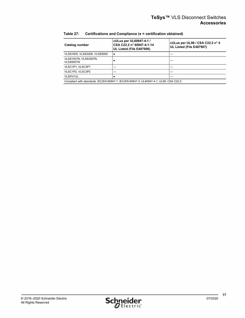
Table 27: Certifications and Compliance (● = certification obtained)
Catalog numbercULus per UL60947-4-1 / CSA C22.2 n° 60947-4-1-14 UL Listed (File E487906)
cULus per UL98 / CSA C22.2 n° 4 UL Listed (File E487907)
VLSS1505, VLSS3005, VLSS5005 ● —
VLSS1507N, VLSS3007N, VLSS5007N ● —
VLSC1P1, VLSC3P1 — —
VLSC1P2, VLSC3P2 — —
VLSFH1UL ● —
Compliant with standards: IEC/EN 60947-1, IEC/EN 60947-3, UL60947-4-1, UL98, CSA C22.2.
TeSys™ VLS Disconnect SwitchesDimensions: 16–125 A Disconnect Switches
1807/2020 © 2016–2020 Schneider Electric
All Rights Reserved™
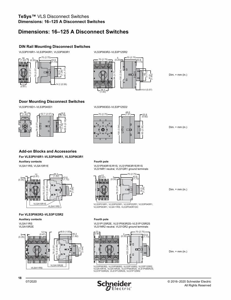
Dimensions: 16–125 A Disconnect Switches
DIN Rail Mounting Disconnect SwitchesVLS3P016R1–VLS3P040R1, VLS3P063R1 VLS3P063R2–VLS3P125R2
Dim. = mm (in.)
Door Mounting Disconnect SwitchesVLS3P016D1–VLS3P040D1 VLS3P063D2–VLS3P125D2
Dim. = mm (in.)
Add-on Blocks and AccessoriesFor VLS3P016R1–VLS3P040R1, VLS3P063R1Auxiliary contactsVLSA11RS, VLSA10R1E
Fourth poleVLS1P040R1E/R1S, VLS1P063R1E/R1S VLS1NR1 neutral, VLS1GR1 ground terminals
Dim. = mm (in.)
For VLS3P063R2–VLS3P125R2Auxiliary contactsVLSA11RS VLSA10R2E
Fourth poleVLS1P125R2E, VLS1P063R2S–VLS1P125R2S VLS1NR2 neutral, VLS1GR2 ground terminals
Dim. = mm (in.)
45 (1
.77)
32.5
(1.2
8)36
(1.42)
22(0.87)
70 (2.75)
14.2 (0.56)
43.9 (1.73)
5(0.20)
74 (2
.91)
78 (3
.07)
43.9 (1.73)
14.4 (0.57)
45(1
.77)
41.9
(1.6
5)
94 (3
.70)
100
(3.9
4)
5(0.20)
70 (2.75)70 (2.75)
38.2(1.50)
55.5
(2.1
8)
44.8
(1
.76)
78 (3
.07)
52.7 (2.07) 19.9(0.78)
36(1.42)
100
(3.9
4)
48.6 (1.91)
65 (2
.56)
70 (2.75) 20.8(0.82)
78 (3
.07)
72.6
(2.8
6)
41.6
(1.6
4)
43.6 (1.72)
46.2 (1.82)
VLSA10R1EVLSA11RS
12(0.47)9
(0.35)43.6 (1.72)
70 (2.75)
78 (3
.07)
32.5
(1.2
8)
VLS3P016R1, VLS3P025R1, VLS3P032R1, VLS3P040R1, VLS3P063R1, VLSA11RS, VLS3P040R1DC
12(0.47) 5
(0.20)
48.9 (1.93)46.2 (1.82)
78 (3
.07)
72.6
(2.8
6)
41.6
(1.6
4)
VLSA11RSVLSA10R2E
12(0.47)9
(0.35)
70 (2.75)43.9 (1.73)
100
(3.9
4)
5(0.20)
VLS3P063R2, VLS3P080R2, VLS3P100R2, VLS3P125R2, VLSA10R1E, VLSA10R2E, VLS1P063R2S, VLS1P080R2S, VLS1P100R2S, VLS1P125R2S, VLS1P125R2
23(0.90)

TeSys™ VLS Disconnect Switches Dimensions: 16–125 A Disconnect Switches
1907/2020© 2016–2020 Schneider Electric
All Rights Reserved™
Mechanical interlock VLS8C1 and mechanical coupling system VLS8M1
Mechanical interlock VLS8C2 and mechanical coupling system VLS8M2
Dim. = mm (in.)78 (3
.07)
45(1
.77)
27(1.06)
89 (3.50)72 (2.83)
VLS8C1 - VLS8M1
45(1
.77)
27(1.06)
89 (3.50)
100
(3.9
4)
140 (5.51)
VLS8C2 - VLS8M2
For VLS3P016D1–VLS3P040D1Auxiliary contacts VLSA11DS
Fourth pole VLS1P040D1E–VLS1P040D1S VLS1ND1 neutral, VLS1GD1 ground terminals
Dim. = mm (in.)
For VLS3P063D2–VLS3P125D2Auxiliary contacts VLSA11DS
Fourth pole VLS1P125D2E, VLS1P063D2S–125D2S VLS1ND2 neutral, VLS1GD2 ground terminals
Dim. = mm (in.)
VLSA11DS
78 (3
.07)
41.6
(1.6
4)
72.6
(2.8
6)
8.5(0.33)
46.2 (1.82)
VLS3P016D1, VLS3P025D1, VLS3P032D1, VLS3P040D1, VLS1P040D1S, VLS1P040D1E
12(0.47)
78 (3
.07)
43 (1.69)
VLSA11DS
8.5(0.33)
46.2 (1.82)
41.6
(1.6
4)
100
(3.9
4)
72.6
(2.8
6)
100
(3.9
4)
23(0.90)
48.6 (1.91)
VLS1P063D2S, VLS1P080D2S, VLS1P100D2S, VLS1P125D2S, VLS1P125D2E, VLS1ND1, VLS1ND2, VLS1GD1, VLS1GD2

TeSys™ VLS Disconnect SwitchesDimensions: 16–125 A Disconnect Switches
2007/2020 © 2016–2020 Schneider Electric
All Rights Reserved™
Rotary handlesVLSH1S5R/B VLSH2S5R/B
Dim. = mm (in.)
VLSH2H5R/B VLSH2H5RD/BD
Dim. = mm (in.)
VLSH3S7NRD/BD VLSH2S5BC
Dim. = mm (in.)
65 (2.56)
65 (2
.56)
61.8
(2.4
3)
23(0.90)
22(0.87)
1–4(0.04–0.16)
Ø3 (0.12)
36 (1.42)
36 (1
.42)
Ø16
(0.6
3)
28–3
2(1
.10–
1.26
)
28–32(1.10–1.26)
36 (1
.42)
48 (1
.89)
36 (1.42)
65 (2.56)
65 (2
.56)
22(0.87)
1–4(0.04–0.16)
35(1.38)
Ø3 (0.12)
Ø16
(0.6
3)
48 (1.89)
65 (2.56)
65 (2
.56)
35 (1.38)34.3 (1.35)1–4
(0.04–0.16)
37 (1
.46)
Ø32.9
(1.29
)
24.3
(0.96
)Ø22.5
(0.88)
3.3 (0.13)
Ø20
(0.79
)
24.3
(0.96
)
Ø22.5(0.8
8)
65 (2.56)
65 (2
.56)
1–4(0.04–0.16)
35.5(1.40)
35(1.38)
Ø22
(0.87
)
3.3 (0.13)
1÷6mm
103.6 (4.08)65 (2.56)
Ø76 (2.99
)
45.7(1.80)
36 (1.42)
36 (1
.42)
Ø32(1.2
6)
Ø 4.2 (0.16)
30(1.18)
65 (2.56)
65 (2
.56)
22(0.87)
1–4(0.04–0.16)
35(1.38)
36 (1
.42)
48 (1
.89)
36 (1.42)
Ø3 (0.12)
Ø16 (
0.63)
48 (1.89)
VLSH4S5R/B Table 28: Dimension A for VLSS Shaft Extensions (see below)
Extension Length mm (in.)
Maximum Dimension A, mm (in.)Type of handle
VLSH 1S5•
VLSH 2S5•
VLSH 2H5R
VLSH 2H5RD
VLSH 2S5BC
VLSS1505 150 (5.90)
194 (7.64)
192 (7.56)
197 (7.75)
211 (8.31)
192 (7.56)
VLSS3005 300 (11.81)
344 (13.54)
342 (13.46)
347 (13.66)
361 (14.21)
342 (13.46)
VLSS5005 500 (19.68)
544 (21.42)
542 (21.34)
547 (21.53)
561 (22.09)
542 (21.34)
Shaft extensions for rear-mounting handles (for Dimension A, see Table 28)VLSS
Dim. = mm (in.)
48 (1.89)16
(0.63) 21.8(0.86)
28–32(1.10–1.26)
28–3
2(1
.10–
1.26
)36
(1.4
2)
36 (1.42)
1–4(0.04–0.16)
Ø3 (0.12)
Ø16
(0.6
3)
Dim. = mm (in.)
VLSS…5 VLSH…5
65 (2
.56)
5 (0.20)
VLS3P016R1…063R1
65 (2.56) A
VLSS..5 VLSH..5VLS3P 063…125R2
65 (2
.56)
5 (0.20)65 (2.56) A
TeSys™ VLS Disconnect Switches Dimensions: 16–125 A Disconnect Switches
2107/2020© 2016–2020 Schneider Electric
All Rights Reserved™
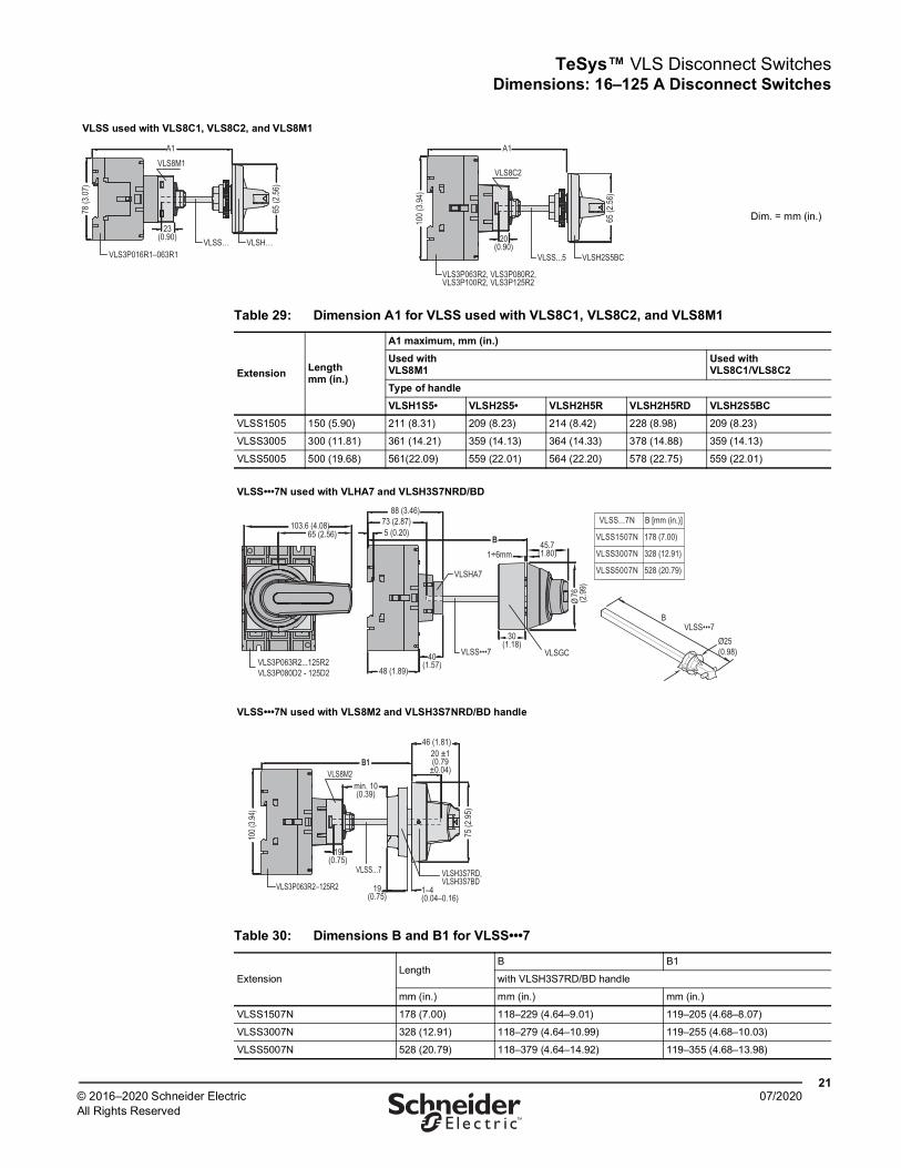
VLSS used with VLS8C1, VLS8C2, and VLS8M1
Dim. = mm (in.)23
(0.90)
VLS8M1
VLSS… VLSH…
A1
VLS3P016R1–063R1
65 (2
.56)
78 (3
.07)
VLS8C2
VLSS...5 VLSH2S5BC
A1
VLS3P063R2, VLS3P080R2, VLS3P100R2, VLS3P125R2
20(0.90)
65 (2
.56)
100 (
3.94)
Table 29: Dimension A1 for VLSS used with VLS8C1, VLS8C2, and VLS8M1
Extension Length mm (in.)
A1 maximum, mm (in.)Used with VLS8M1
Used with VLS8C1/VLS8C2
Type of handleVLSH1S5• VLSH2S5• VLSH2H5R VLSH2H5RD VLSH2S5BC
VLSS1505 150 (5.90) 211 (8.31) 209 (8.23) 214 (8.42) 228 (8.98) 209 (8.23)
VLSS3005 300 (11.81) 361 (14.21) 359 (14.13) 364 (14.33) 378 (14.88) 359 (14.13)
VLSS5005 500 (19.68) 561(22.09) 559 (22.01) 564 (22.20) 578 (22.75) 559 (22.01)
VLSS•••7N used with VLHA7 and VLSH3S7NRD/BD
VLSS•••7N used with VLS8M2 and VLSH3S7NRD/BD handle
Table 30: Dimensions B and B1 for VLSS•••7
ExtensionLength
B B1
with VLSH3S7RD/BD handle
mm (in.) mm (in.) mm (in.)
VLSS1507N 178 (7.00) 118–229 (4.64–9.01) 119–205 (4.68–8.07)
VLSS3007N 328 (12.91) 118–279 (4.64–10.99) 119–255 (4.68–10.03)
VLSS5007N 528 (20.79) 118–379 (4.64–14.92) 119–355 (4.68–13.98)
48 (1.89)
88 (3.46)73 (2.87)5 (0.20)
40(1.57)
VLSS•••7
VLSHA7
B1÷6mm
103.6 (4.08)65 (2.56)
Ø
VLSGC
VLSS...7N B [mm (in.)]
VLSS1507N 178 (7.00)
VLSS3007N 328 (12.91)
VLSS5007N 528 (20.79)
B
Ø25(0.98)
VLS3P063R2...125R2 VLS3P080D2 - 125D2
VLSS•••7
45.7(1.80)
30(1.18)
76 (2.99
)
VLS8M2B1
VLS3P063R2–125R2
VLSS...7 VLSH3S7RD, VLSH3S7BD
1–4(0.04–0.16)
19(0.75)
46 (1.81)
75 (2
.95)
20 ±1(0.79
±0.04)
min. 10(0.39)
19(0.75)
100 (
3.94)
TeSys™ VLS Disconnect SwitchesWiring Diagrams
2207/2020 © 2016–2020 Schneider Electric
All Rights Reserved™
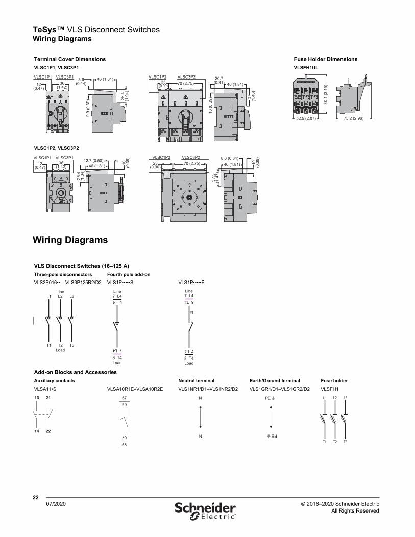
Wiring Diagrams
Terminal Cover Dimensions Fuse Holder DimensionsVLSC1P1, VLSC3P1 VLSFH1UL
VLSC1P2, VLSC3P2
VLS Disconnect Switches (16–125 A)Three-pole disconnectorsVLS3P016•• – VLS3P125R2/D2
Fourth pole add-onVLS1P•••••S VLS1P•••••E
Add-on Blocks and AccessoriesAuxiliary contacts Neutral terminal Earth/Ground terminal Fuse holderVLSA11•S VLSA10R1E–VLSA10R2E VLS1NR1/D1–VLS1NR2/D2 VLS1GR1/D1–VLS1GR2/D2 VLSFH1
VLSC3P1VLSC1P1
12(0.47)
36(1.42)
46 (1.81)
26.4
(1.0
4)
9.9
(0.3
9)
3.6(0.14) 46 (1.81)
37
(1.4
6)
23(0.90)
20.7(0.81)
VLSC3P2VLSC1P2
10 (0
.39)
70 (2.75)
52.5 (2.07)
80.1
(3.1
5)
75.2 (2.96)
VLSC1P1 VLSC3P112
(0.47)36
(1.42) 46 (1.81)12.7 (0.50)
10(0
.39)
26.4
(1.0
4)
VLSC3P2VLSC1P2 70 (2.75)23
(0.90)
10(0
.39)
37.3
(1.4
7)
46 (1.81)8.6 (0.34)
L1 L2
T1 T2
L3
T3
Line
Load
7 L4Line
Load
8 T4
7 L4
8 T4
N
7 L4Line
Load
8 T4
7 L4
8 T4
13 21
14 22
57
68
67
58
N
N
PE
PE
L1 L2
T1 T2
L3
T3

TeSys™ VLS Disconnect Switches Wiring Diagrams
2307/2020© 2016–2020 Schneider Electric
All Rights Reserved™
Table 31: Technical Specifications, VLS Range, 16–125 A
Model3-pole: VLS3P… 016… 025… 032… 040… 063R1 063R2 080… 100… 125…4th pole: VLS1P… 040… 040… 040… 040… 063R1S 063R2S 080… 100… 125…
Contact SpecificationsIEC conventional free air thermal current, Ith (≤40°C) A 16 25 32 40 63 63 80 100 125IEC rated insulation voltage, Ui V 1000IEC rated impulse withstand voltage, Uimp kV 8IEC rated operational current, Ie
AC21A400 V A 16 25 32 40 63 63 80 100 125500 V A 16 25 32 40 63 63 80 100 125690 V A 16 25 32 40 63 63 80 100 125
AC22A400 V A 16 25 32 40 45 63 80 100 125500 V A 16 25 32 40 45 63 80 100 125690 V A 16 25 32 40 45 63 80 100 125
AC23A400 V A 16 25 32 40 45 63 80 100 125500 V A 16 25 25 25 25 63 63 80 100690 V A 16 25 25 25 25 47 47 47 47
IEC rated operational power
AC23A400 V kW 7.5 11 15 18.5 22 30 45 55 55690 V kW 11 22 22 22 22 45 45 45 45
IEC reactive power for capacitor control 400 V kvar 7.5 10 12.5 15 15 25 30 40 50IEC protection against short-circuit
Rated short-time withstand current (1s), Icw A rms 800 2500Rated conditional short-circuit current kA rms 50With fuse class gG A 16 25 32 40 63 63 80 100 125
IEC making capacity (AC23A 400 V) A 400 450 1250IEC breaking capacity (AC23A 400 V) A 320 360 1000Mechanical life cycles 100,000 100,000 30,000Electrical life (IEC AC21A) cycles 100,000 15,000 30,000UL/CSA general use at 600 V A 16 25 32 40 50 60 100 100 100UL/CSA short-circuit rating at 600 V kA 5 5 5 5 5 10 10 10 10UL/CSA fuse class/max rating at 600 V Type/A RK5/20 RK5/30 RK5/35 RK5/45 RK5/45 –/100 –/100 –/100 –/100UL/CSA HP ratings
Single phase 120 V HP 1 1.5 2 2 2 3 3 5 7.5240 V HP 2 3 5 5 7.5 7.5 10 10 10
Three phase
200-208 V HP 5 7.5 10 10 10 20 25 30 25240 V HP 5 7.5 10 15 15 20 30 30 30480 V HP 10 15 20 20 30 40 40 50 50600 V HP 10 20 20 25 30 40 40 60 40
Terminals
Type Lug clamp [1]
A mm 5.6 mm (0.22 in.) 12.4 mm (0.49 in.)B mm 6.5 mm (0.26 in.) 10.4 mm (0.41 in.)Screw M4 M8Tool Phillips 2 Metric Allen key 4
Tightening torque N•m 1.8–2 5–6lb-in 16–18 45–54
Conductor section (solid/stranded)
mm² 0.75–16 4–50AWG 18–6 12–1
Ambient Conditions
TemperatureOperating °C −25 to +55Storage °C −40 to +70
Maximum altitude m 3000
Mounting positionNormal VerticalAdmissible Any
Mounting Screw or 35 mm DIN rail (IEC/EN 60715)[1] IEC/EN 60947-1 designation: Pillar terminal.
B
A

Schneider Electric USA, Inc.800 Federal StreetAndover, MA 01810 USA888-778-2733www.schneider-electric.us
Schneider Electric and TeSys are trademarks and the property of Schneider Electric SE, its subsidiaries, and affiliated companies. All other trademarks are the property of their respective owners.9400CT1601R07/20 © 2016–2020 Schneider Electric All Rights Reserved
07/2020