testronic laboratories usb testing - · pdf file–too fast edges (< 500ps) ... –...
TRANSCRIPT
Testronic Laboratories
USB Testing
Pascal Berten
Testronic Labs nv
Wetenschapspark 7
Diepenbeek, Belgium
Web: www.testroniclabs.com
Tel: + 32 (0) 11 56 04 39
Mobile +32 (0) 475 85 32 17 1

Agenda
Introduction Testroniclabs
USB-IF Compliance program
Limitations of the USB-IF Compliance program
Most common issues
– Electrical
– Power consumption
– USBCV
– Link Layer testing
– Interoperability
New USB 2.0 standards
– Battery Charging
– OTG and Embedded Host 2

YOUR PROJECT or
PRODUCT
Wy TL?
TESTRONIC LABORATORIES
Offices in USA (2), UK (2), Belgium and Poland
Owned by:
CATALIS
German Stock Exchange listed
Non operational Holding focussed on non-IP services to the Digital Media Industries
2008: 40 mln euros consolidated revenues - very sound and stable financial ratio’s
Who we are?
3
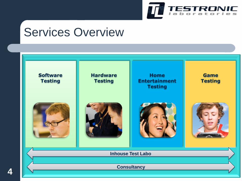
Inhouse Test Labo
Consultancy
Game Testing
Home Entertainment
Testing
Hardware Testing
Software Testing
Services Overview
4

Company Services
Interoperability
Certification
Official certification:
USB certification for all CE/PC products
Wireless USB
IEEE-1394 (Firewire)
DLNA
SATA
Pre-certification and pre-compliance testing:
PCI Express DLNA
WHQL SATA
HDMI Wi-Fi
DVI USB for all products
Ethernet Bluetooth
IEEE-1394 (Firewire) WiMedia
JavaVerified Wireless USB
Digital
Television
IRD / Set-top boxes
Back-end systems
DTV Compatibility
Laboratories
Testronic Laboratories
Software Hardware
On-site testers Consultancy
Interactive
Software
Websites
CD-ROMs/DVD-ROMs
Standalone Applications
Networked Systems
Games
Nintendo
Sony
Microsoft
PC
PC &
Consumer
Electronics
Internal Interfaces
External Interfaces
Home Networking
Storage
Embedded Software
Film
DVD
Blu-ray
Interactive
5

Consultancy or Inhouse Test Lab
Devices Certification
o System Level QA
o Early developments
o Final products
o Component Level
o FPGA boards
o Reference Design
o Low Level Software
o Drivers, Firmwares
o Embedded Apps.
o USB (All products)
o Serial ATA
o DLNA
o WiMedia
o ExpressCard
o IEEE-1394
Software Testing Hardware
Testing
Hardware Testing - Certification
Pre- Certification
o PCI Express
o HDMI/ DVI
o WHQL
o MIPI…
6
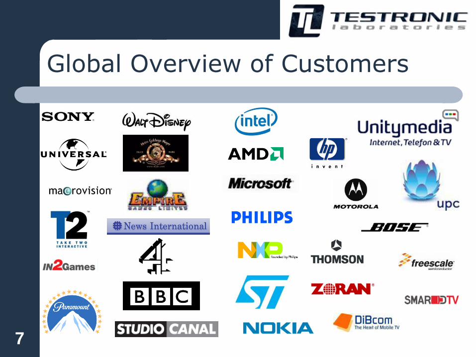
Global Overview of Customers
7
USB-IF Compliance program
Testing a DUT against set rules / Test
specifications of a technical organization
Ensure interoperability in an interconnected
environment
Set a bar that is high enough to promote the
technology
Set a bar that is low enough to encourage
vendors to obtain a logo
8

Why obtain the logo?
Certified logo usage only after passing the certification program
Ensure interoperability across other products
Give the vendor and customer confidence that the product is
compliant according to the specification
Product will be listed on the Integrators List at WWW.USB.ORG
Some computer stores sell require the product to certified
OEM, Silicon or IP providers give their customers the
confidence that their product is capable in getting certified.
9

USB-IF Compliance test
IOP
Avg
Cu
rren
t
US
BC
V
Back-
Vo
ltag
e
SS
Ele
ctr
ical
HS
Ele
ctr
ical
FS
Ele
ctr
ical
OT
G t
ests
Ch
ecklists
FS D
HS D
FS H
HS H
SS D
SS H
FS OTG
HS OTG
10

Limitations of USB-IF compliance plan
Certification is not a replacement for validation
Latest USB specs are not covered (Battery
Charging, OTG 2.0, UASP, MTP...)
Protocol not covered (USB 2.0 Ch8)
Testing is done under limited variations
– One Operating systems
– One IOP system setup (Goldtree)
– Interoperability tested against a limited set of devices
– Only tested under ambient conditions
– Electrical clean environment
– In spec testing (often devices and host are out spec)
11

Full Low Speed Electrical
Legacy electrical test – Signal Quality (EYE)
– Inrush
– Drop/Droop
Device and/or Host FS Signal Quality – Make sure you capture the correct packet (packets from
host/hub are on the same D+/D- line as from the device
side)
– Make sure you use the latest USBET (www.usb.org)
– Some ESD and/or EMI components make the eye failures
12

Full Low Speed Electrical
Device and/or Host FS/LS Signal Quality
– Measured after the required legth of cable
Std B / Std A receptacle = 5m
– USB silicon is advisable to measure after 5m
– USB host must be measured after 5m from Std A recep
Mini B receptacle = 4.5m
Micro B receptacle = 2m
– Make sure the external clock of the USB silicon is set
properly
– Not use long internal cables (e.g. ehosts inside a car)
13

Inrush current
Device Inrush (< 50µC)
– Make sure you have the correct setup
Calibrate current probe (set it to 0mA before measuring)
Use the latest USBET
Capture a period of 100ms
– Not use a too large capacitor over Vbus and GND (> 10µF)
– If soft-start circuit is available make sure it’s well adjust
– Test the device also without external power connected
– Test with empty battery
14
Host/Hub Drop Droop
Host/Hub Vbus Drop (4.75V and 5.25V) Droop
(330mV) – Make sure the full length of the Vbus PCB trace is wide enough for
the maximum current Vbus must handle.
– Use a large capacitor over Vbus to avoid Vbus droop failures.
– Differences in Fixtures
– Make sure a good power supply is used that can handle the full
stressed system + full load of Vbus USB.
– Do additional stress tests
Keep in mind that there are allot of device that consume more power than
the USB spec allow (e.g. battery charging devices, external hard drives,
iPod like devices,…)
Test with more load
Test an over current event
15
Back Voltage
Device Back Voltage (<400mV)
– Measure the voltage over Vbus, D+, D- and GND this
should be less than 400mV
– Some devices have their pull-up resistor at all times high
even when Vbus is not connected. This will result in ~3V
between D+ and GND
16
High Speed Electrical
High Speed Electrical – Signal Quality (eye)
– Receiver sensitivity
– Chirp, Packet Parameter, Suspend/Resume/Reset, Test
J/K/SE0_NAK
Device and/or HS Signal Quality – Support of HS electrical test modes
Embedded Host or OTG A device often not enter the required HS
electrical test modes via the required VID/PID detection!!!
17
High Speed Electrical
Device and/or Host HS Signal Quality – It’s known that there are differences between HS EYE
diagrams depending on the setup. Since the edges are
becoming faster and faster this is becoming more
problematic. Things that effect the differences are:
Fixtures
USB Adapters (short cable or adapter between fixture and DUT)
Probe (different type and bandwidth)
Probing tips
USBET
– Take multiple eye diagrams or measure a real time eye
since some products will randomly fail
18

High Speed Electrical
Device and/or HS Signal Quality
– PCB Impedance mismatch (eye failures)
External clock not set properly (jitter or data rate failure)
Too long traces or internal cables (for a host it’s always near
end at the A receptacle even if there is internal cable)
– Too fast edges (< 500ps) New silicon is becoming faster (even certified once)
Make sure you measure as near as possible to the device
If require add capacitors or extend the length D+/-
19

High Speed Electrical
Receiver testing
– No squelch (still answer all NAK) < |150mV|
– Squelch (no more answer NAK) > |100mV|
New PHY’s often have the capability to
change some electrical parameters like Tx
EYE amplitude or Receiver settings, make
sure they are set for your design
20
Super Speed Electrical
Products not send out the required CP0 or CP1 or
they not stay in this mode.
Not enter loopback for Rx
SSC (spread spectrum clocking) is mandatory but is
not always enabled
– There are hosts that incorrectly use centre-spread SSC
instead of down-spread SSC what will result in Interop
problems.
Receiver setup problems
– Setup not calibrated
– Broken fixtures (or too mush used)
– Bad 3m cable
21

Power consumption
Measure current when external power is removed
Measure current in worst case
– When activating all interfaces
– Empty battery
Measure the current states with USBCV
– Unconfigured current (USB 2.0 <100mA; USB 3.0 <150mA)
– Configured current (< max power descriptor USB 2.0 < 500 mA USB 3.0
900mA)
Suspend current < 2.5mA
– When remote wakeup feature is supported enable it
– Measure when system is in S3 and see if Vbus is still on
22

Power consumption
Devices and Hubs that claim to be self powered only
but also operate bus powered.
– If a device claim to be self powered the maximum power
consumption is 100mA. It’s than not allowed to operate in
bus powered mode and consume more.
– If a USB 2.0 Hub claim to be self powered it should be able
in handling 500mA/port a bus powered hub 100mA/port.
However ~80% of the self powered hubs on the market
work in bus powered mode and claim to be self powered.
23

USBCV
All products must pass USB20CV and
USB30CV
USB30CV on Renesas and Fresco xHCI
Devices must pass Chapter 9 and all other
classes supported by device and USBCV
– HID, MSC, UVC, PHDC, HUB, OTG
Devices must pass all supported speeds
– High Speed must also pass Full Speed
– Super Speed must also pass High and if
supported Full Speed
24

USBCV
LPM supported devices should be tested on
Fresco Logic and pass the LPM test
Use a HS Hub with Vbus switching for run
USB20CV Ch9!!!
– This will test if a device will be ready after 1
second that Vbus is switced on.
It’s advisable to run USBCV in different
combinations of hubs and hosts.
25

USBCV
Wrong USB version 1.1 this should be at
least 2.0
Device claim the wrong power state bus/self
powered.
When remote wakeup feature is enabled it
will be tested.
26

Super Speed Link Layer Testing
Link Layer (Chapter 7) testing will become
mandatory to pass July 2011
Also run the additional test the Ellisys
Examiner has:
– Chapter 6 (Physical layer test)
– Power consumption test
– Vbus acceptance test
27

Super Speed Link Layer Testing
Pending HP Timer Deadline
The Port Under Test (PUT) receives the LGood prior to the HP timer deadline (3us)
but still initiates a recovery. This indicates the PUT does not recognize the LGood
in time. PUT should stay in U0, as the LGood is sent within the limits of the
specification (near the 3us deadline).Recommendation: Relax the HP timer to more
than 3us to give internal logic time to process incoming link command. Spec allows
for +50% tolerance.
28

Super Speed Link Layer Testing
TPortConfiguration Issue
The link test specification requires that the PUT complete the sending of Port
Capabilities and Port Configuration LMPs within tPortConfiguration (20us) before
most tests can be continued/executed. Some silicon designs improperly “gate” the
sending of these LMPs upon receipt of these same LMPs from the host (or in our
case, from Examiner). PUT must send these asynchronously (without regard for
whether host/Examiner has sent them. The above example is a correct example
(note PUT sends first and well within tPortConfiguration).
29

Super Speed Link Layer Testing
Device Reaction to CRC5 Error
Per errata released in 6/2010, a PUT must initiate recovery upon receipt of a single
CRC5 error in a link command. In this case, the PUT does not initiate a recovery; it
stays in U0.
Recommendation: Ensure new silicon meets errata requirements.
30

Device Interoperability
In order to pass USB-IF compliance you
must pass the Goldtree
Most common failure on the Goldtree are
– First installation of the device
– Development SW is not stable enough
– Active suspend resume
S1, S3, S4
Remote wakeup
Device, SW application, driver must be able handling
this.
31

Extended Device Interoperability
Interoperability is the most important test
Make sure that the device is tested:
– All supported OS
– Different Host controllers
– Different hubs
– Suspend states
– Interop with other devices
– Test your device on various embedded systems!!
32

Battery Charging 1.2 Spec
PD (Portable Device)
– Max 1.5A
CDP (Charging Downstream Port)
– Is also a regular USB Host
– > 1.5A
– Detection mechanism D+/-
DCP (Dedicated Charging Port)
– No other USB functionality
– > 0.5A < 5A
– D+/- shorten for detection (< 200 Ohm)
Do not expect that all USB chargers and devices interop
with each other. It’s advisable to do a wide interoperability
test
33

Battery Charging 1.2
ACA (Accessory Charger Adapter)
– Is some sort of docking with different flavors
– Is a charging adapter that can be place between OTG or EH
– Allowed to expand your charging ports
Currently the USB-IF not require specific battery
charging tests. Except for the dead battery test by
plugging in the BC device with dead battery in a USB
hub and see that it not consume more than 100mA.
Testing of BC compliance plan is not final and for
details please check the BC Work Group.
PET (MQP) is currently testing the 0.9 spec
34
OTG & Embedded Host 2.0
OTG & EH 2.0 Spec VS OTG 1.3 – Include EH
– Remove Vbus SRP
– HW changes in order to support BC
– Clarification on user experience and TPL
– New Feature ADP (Attach Detection Protocol)
– “Limited” OTG (no SRP support)
– Additional Test modes (in order to run PET)
Current USB-IF Compliance program is still 1.3 – 2.0 Compliance program is in 0.9 faze
– Still use the obsolete OPT
– No ADP
– Interoperability is vague
35

OTG & Embedded Host 2.0
Mirco AB is only allowed for OTG products
Mini AB is not allowed anymore
Manual SRP should be possible for testing
Implement all new testing VID/PID detection
OTG A and EH is almost same testing
– For OTG A most often an microA to StdA adapter
is required.
36

OTG A and EH Interoperability
Make clear messages
– When devices are not supported
– Over current event
– Lack of performance (MSC not fast enough)
– Hub scenario’s
– …
Suspend Resume – Not mandatory
– Make possible to test
Try to avoid hubs support (if not make sense not support hubs).
– Make sure a clear “hub not supported” message
– Make sure no devices will be enumerated behind the hub
37
OTG A and EH Interoperability
If hubs should be supported take following
into account: – Max tier of hubs (error message when exceeding)
– Max concurrently devices supported should be defined
– Devices should be able to operate concurrently and
independent or a selection method should be implemented.
– Over current message
– Should be able to handle legacy hubs (or error message)
– Should be able in handling bus powered hubs
When connecting a high power device a message should appear and
the device should not enumerate
38

OTG A and EH Interoperability
If EH has multiple ports
– Devices should be able to operate concurrently and independent or a
selection method should be implemented.
– Should pass Droop test (< 330mV voltage drop on other port)
Class support
– Is officially not allowed by the USB-IF
– Class support is virtually impossible
– MSC has allot of subclasses (Floppy, CDROM, flash card readers,
MSC with multiple interfaces, internal hubs, …)
– The SCSI transparent subclass is most used
SCSI however has many variants (www.t10.org)
– UASP is coming along
– Mouse and Keyboard are not a class
39
Checklists
For USB-IF compliance the product must be
registered at USB.ORG and the checklist must be
submitted
Make sure that the receptacles and/or cables used
are USB-IF certified and have a TID!!!
If USB silicon is not certified as silicon provider to
provide you with the complete filled out Checklist
Embedded Hosts or OTG products must submit a
Target Peripheral List (TPL)
40

Waivers
These are “permitted” failures on the test
specifications
Not unconditionally and not for ever
Provided by the USB-IF, not by the Testlab
Only granted in special occasions
– (for example incorrect behavior of OS)
41

References
http://www.usb.org
– Specification, Test Specification, Test tools, Workgroups, …
http://compliance.usb.org
– All latest USB-IF Compliance updates
http://testusb.com
– Part of Testroniclabs
– Work in progress but already some topics
– Embedded Host tester (force the EH or OTG product in the
required test mode)
– More USB testing product to come (short cables, fixtures, …
42

Why test @ Testlab
Testlab vs USB-IF compliance
– No Travel costs
– Developer is not tied the USB-IF schedule for tests runs
– Not need to wait till there is an event
– Debugging is hard
– Confidentiality
ICV has the latest Agilent and Ellisys equipment
ICV is trained with latest test procedures, technology and use of the
test environment
TL can do more in depth test on multiple layers – Electrical
– Protocol
– Framework
– Interoperability
– Environment
43

Why test @ ICV
Go beyond USB-IF program – Consulting USB design
– Testing under different temperature
– Testing on Host and Hub controllers
– Testing on Multiple OS’s
– Testing on Embedded Systems
– Testing on different devices (e.g. + 250 MSC devices)
– In depth electrical (jitter tolerance, out spec, …)
– Testing on different languages
– WHQL (MS logo)
– Ch8ck
44

Questions
45

Contacts
Johan Craeybeckx
– Chief Technology Officer (CTO)
– Email: [email protected]
Pascal Berten
– Senior Certification Engineer
– Email: [email protected]
Kristof Mommen
– Certification Engineer
– Email: [email protected]
46