testing of internal combustion...
TRANSCRIPT

7TESTING OF INTERNAL COMBUSTION ENGINES
7.1 Objectives of TestingIn general, the purposes of testing an internal combustion engine are :
(i) to obtain information about the engine which cannot be determined by calculations,(ii) to confirm data used in design, the validity of which is in doubt, and(iii) to satisfy the customer as to the rated power output with the guaranteed fuel
consumption.The majority of tests on internal combustion engines are carried out for commercial
purposes in order to check the following :(i) rated power (brake power) with the guaranteed fuel consumption (kg/kW-hr.),(ii) the quantity of lubricating oil required on brake power basis per kW-hr.,(iii) the quantity of cooling water required on brake power basis in kg per kW-hr.,(iv) the steadiness of the engine when loaded at different loads, and(v) the overload carrying capacity of the engine.
7.2 Thermodynamic TestsComplete thermodynamic tests are quite different from the commercial tests. They are
carried out for the purpose of comparing actual results with the theoretical or ideal performance. For such tests it is necessary to measure losses in addition to the useful part of the energy, and also to draw up a heat balance account. Such trials have been (the direct cause of, and incentive to, the improvement in heat engines throughout the period of their development. This interest created a demand for authentic records of engine performance, which could only be satisfied by exhaustive trials carefully observed ;jand calculated. The measurements necessary to determine the mechanical and thermal jefficiencies of the engine and to draw up the heat balance account are :
(i) Indicated power (if possible); |(ii) Brake power;(iii) Morse test for mechanical efficiency in case of multi-cylinder high speed engines;(iv) Rate of fuel consumption and its calorific value;(v) Rate of flow of cooling water and its rise of temperature, for calculating the j
heat carried away by jacket cooling water; !(vi) Heat carried away by the exhaust gases - this is estimated either directly by }
exhaust gas calorimeter or by measuring air consumption and temperature of M exhaust gases, and engine room temperature. j
7.2.1 Measurement of indicated power : It is extremely difficult to determine the tiindicated power, especially when moderate or high engine speeds are used. The strength 1of the spring to be used in the indicator must be carefully chosen. The ratio of maximum ifpressure in the engine cylinder to the mean pressure during the cycle in an I.C. engine * is much greater than that of any other heat engine. For gas and petrol engine, the i
iii

Testing of Internal Combustion Engines 171explosion causes the maximum pressure to be reached practically instantaneously. Thus, to prevent vibrations being set up, the spring used must be stiff but at the same time it should give enough height of the indicator diagram. The production of true volume scale is often hindered by the absence or inaccessibility of any suitable point of attachment for the indicator cord, so that it may transmit the piston movement, such as is provided by the cross-head of a steam engine. Any miniature crank or cam device attached to the crank shaft must be phased with considerable accuracy, while slackness, inertia and elasticity in the mechanism may give very serious results.
The piston and pencil element used in steam engine practice is useless except at very low speeds, the rate of pressure rise causing violent oscillatlbns which cannot be damped without introducing errors. The replacement of the piston by a diaphragm and the use of high optical or electrical magnification of its deflection, reduce the oscillation problem but fatigue of the diaphragm metal and change of its calibration by heat are both likely to occur. If the diaphragm is separated from the cylinder by means of a cock except during actual recording, these troubles may be reduced, but likely to be replaced by others due to surges of the gas pressure in the connecting passages, and even when these are short the time taken for a change of pressure in the cylinder to reach and deflect the diaphragm, may introduce a phase lag which is serious at high engine speeds.
For rapid determination of the mean effective pressure, a planimeter may be used, being quite accurate enough forv all ordinary practically purposes.
The remaining data required for the calculation of the indicated power are the number of explosions or power strokes per minute and the dimensions of the engine cylinder. The number of explosions per minute is best given by means of a counter arranged to be actuated from the gas valve, particularly if the engine is governed by the hit and miss method.
Owing to the difficulties of accurate measurement, particularly at high speeds, there is an increasing tendency to disregard indicated power and rely on brake power\ as a power measurement.
7.2.2 Measurement of brake power : There is very little difficulty in measuring this quantity accurately if ordinary precautions are taken. This may be obtained by the use of either a mechanical, electrical, hydraulic or air brake, etc. The difference between the indicated power and brake power is known as the mechanical or friction loss, and includes the negative loop of the indicator diagram. The following method is adopted to determine the friction power so that the indicated power may be accurately determined.
Motoring test : An approximate value of friction power may be found immediately following a period of running, by measuring the power required to motor the engine (the engine is driven by an electric motor) at the requisite speed and with the ignition switched off. Such a test should be carried out as near as maximum operating temperature possible, the viscosity of the lubricant rising very considerably with a fall of temperature. Unfjprtunately the thin film of lubricant on the cylinder wall, the shearing of which is the cause of about half the total engine friction, suffers considerable deterioration by heat and oxidation while the engine is running, and on switching off the ignition, this damaged oil on which the piston normally operates, is rapidly washed from the walls and replaced by oil in good condition. The power required to motor the engine thus falls very rapidly within perhaps two minutes, after which it begins to rise slowly owing to the cooling of wails. A reasonable accurate determination of running friction is, therefore, very difficult, if not impossible with normal test equipment.
7.2.3. “ Morse” test for mechanical efficiency : For multi-cylinder high speed engine the Morse test is available, and is less open to objection that the simple motoring test.

The method of finding indicated power o f one cylinder o f a multi-cylinder I.C. engine without the use of a high speed indicator is known as the Morse test. The engine is first run under the required condition of load, speed, temperature, etc., and the brake power is measured accurately. Each cylinder is then cut-out in turn; the brake load being rapidly adjusted in each case to bring the engine speed back to the specified value at the given angle of advance and throttle settling.
The fundamental assumptions are that the friction and pumping power of the cut-out cylinder remains the same after cutting out as they were when the cylinder was fully operative (developing power). This would not be a correct assumption if it were not for the fact that it is possible to carry this test in a very short span of time. It should only take a few seconds to cut out one cylinder and adjust the brake load to keep the speed constant. Over this short period the assumption may be considered reasonable. After cutting out one cylinder, the engine should be allowed to run on all cylinders for a shortwhile, before cutting out the next cylinder.
Suppose we have a four-cylinder petrol engine loaded with a hydraulic brake (dynamometer) to measure its brake power. At any given speed with all the four cylinders firing (developing power), the brake power should be accurately measured, Then,
Indicated power 4 cylinders = Brake power 4 cylinders + Friction power 4 cylinders (i)If one cylinder is cut out (spark plug lead is shorted) so that it develops no power,
the engine speed will fall. The brake load should then be reduced so that the enginespeed increases again to the original given speed. The engine is now developing powerin three cylinders, whereas the friction power of all the four cylinders remains the same as already discussed.
Then, the brake power should be measured with the decreased load, i.e., with three cylinders developing power.
Then, l.P. 3 cylinders = B.P. 3 cylinders + F.P. 4 cylinders •••(••)Subtracting (ii) from (i), we get,l.P. 4 cylinders " l.P. 3 cylinders ~ B.P. 4 cylinders - B.P. 3 cylinders
where, B.P. = Brake power, l.P. = Indicated power and F.P., = Friction power.But, l.P. 4 cylinder - l.P. 3 cylinders is the l.P. of the cylinder that was cut out and
hence may be calculated as the difference in readings of B.P. measured when all cylinders were firing and when one cylinder was cut out (i.e., only three cylinders were firing).
By cutting out each cylinder in turn, the l.P. of each cylinder can be determined and the indicated power of the whole engine is then sum of I.P.’s of the separate cylinders. The friction power is given by : total l.P. - total B.P. and the mechanical efficiency is given by dividing the total B.P. by the total l.P. (see illustrative problem No. 10).
7.2.4 Measurement o f rate of fuel consumption and its calorific value : This is very easily measured for small capacity engine by noting the time taken to consume a given volume of fuel, although strictly speaking it is the mass of the oil that is required. A simple device, in which two special glass bulbs, one of about 100 c.c. capacity and the other 200 c.c. capacity, may be connected by three-way cocks to the fuel tank and the engine fuel supply line. Three-way cocks help to fill the one bulb when the other is feeding the engine. To reduce the fuel consumption to a mass basis,, the specific gravity of the fuel oil should be determined, at the temperature of the oil during the trial.
For bigger size oil engine, the simplest and the most accurate method of obtaining the fuel consumption is to support the fuel tank on a weighing machine and supply fuel to the engine. The rate of fuel consumption is then obtained by subtracting the mass of the fuel and tank at the end of the trial, from that at the beginning, the time taken to
172 Elements of Heat Engines Vol. II

Testing of internal Combustion Engines 173
discharge this mass of fuel being noted.The most reliable method of measuring the gas consumption of a gas engine is to
pass the gas through a graduated gas holder from which it is drawn by the engine. This is more accurate than the use of a gas meter. The temperature and pressure o f the gas should be taken, so that the volume used may be reduced to normal or standard temperature and pressure.
A trial of half an hour or even less should suffice, if the engine has settled down to its working conditions.
The heat engine trials committee has recommended to use the gross or higher calorific value of the fuel for the calculation of thermal efficiency and drawing up the heat balance sheet. The higher calorific value for oil fuel can be determined by using Bomb calorimeter and that for gaseous fuel by using Junkers gas calorimeter. vI
7.2.5 Measurement of heat carried away by cylinder jacket cooling water : In ordinary internal combustion engines, the circulation of cylinder jacket cooling water is maintained by means of natural gravitational current of water or by forced circulation from a pump. In measuring the heat carried away by the jacket water it is necessary to measure the rate of flow of jacket cooling water and also the inlet and outlet temperatures of water. The rate of water circulated in the cylinder jacket is measured by means of water meter fitted in the inlet pipe or by collecting the outflow water in a measuring vessel in a given time interval. The measuring vessel should be supplied with gauge glass reading either in litres or kilograms, or it may be carried on a weighing machine and the mass of water collected in a given time obtained directly. In order to determine the temperature difference all that is necessary is to have two reasonably accurate mercury thermometers which should be inserted in suitable pockets arranged on the inlet and outlet pipes close to the engine.
Let, mw = mass of cylinder jacket cooling water supplied in kg per minute, t i m inlet temperature of jacket cooling water, °C, fe = outlet temperature of jacket cooling water, °C, and K = specific heat of water, kJ/kg K.
Then, heat carried away by cylinder jacket cooling water per minute= mass of cooling water per min. x specific heat of water x rise in temperature
of cooling water= mw x K x (fe - ft) kJ/min. ..(7.1)
There is no reliable method of measuring directly the heat carried away by the airflowing over an air cooled engine and therefore this quantity should be included in the radiation losses, i.e., in the last item of the heat balance sheet.
7.2.6 Measurement of heat carried away by the exhaust gases : In the actual determination of heat carried away by exhaust gases, we are concerned with three quantities, namely the temperature of exhaust gases and room temperature, the mass of exhaust gases, and the mean specific heat of exhaust gases.
Temperature of exhaust gases : The temperature of exhaust gases (tg) as they leave the engine cylinder can be measured by a thermometer known as pyrometer. It works on the principle that when two dissimilar metals are joined together, heating will cause a flow of'electricity. The thermo-couple is encased in a tube which is screwed into the exhaust connection of the cylinder. Two wires lead from the thermo-couple to a milli-voltmeter which indicates the minute e.m.f. created by the flow of electricity. The dial of the pyrometer is marked in terms of temperature degrees instead of milli-volts, having been
calibrated by the makers. The warmer the gases, the greater will be the e.m.f. ( milli-volts) and the pyrometer dial will read higher temperature.
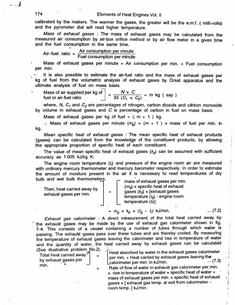
Mass o f exhaust gases : The mass of exhaust gases may be calculated from the measured air consumption by air-box orifice method or by air flow meter in a given time and the fuel consumption in the same time.
Air-fuel ratio - Air consumption per minute Fuel consumption per minute
Mass of exhaust gases per minute = Air consumption per min. + Fuel consumption per min.
It is also possible to estimate the air-fuel ratio and the mass of exhaust gases per kg of fuel from the volumetric analysis of exhaust gases by Orsat apparatus and the ultimate analysis of fuel on mass basis.
174 Elements of Heat Engines Vol. II
Mass of air supplied per kg of fuel or air-fuel ratio
N x C = m kg ( say )33 (C, x q>)
where, N, C1 and C2 are percentages of nitrogen, carbon dioxide and carbon monoxide by volume in exhaust gases and C is percentage of carbon in fuel on mass basis.
Mass of exhaust gases per kg of fuel = (. m + 1 ) kg.Mass of exhaust gases per minute (mg) = (m + 1 ) x mass of fuel per min. in
kg.Mean specific heat of exhaust gases : The mean specific heat of exhaust products
(gases) can be calculated from the knowledge of the constituent products, by allowingthe appropriate proportion of specific heat of each constituent.
The value of mean specific heat of exhaust gases (Ap) can be assumed with sufficient accuracy as 1 005 kJ/kg K.
The engine room temperature (Q and pressure of the engine room air are measured with ordinary mercury thermometer and mercury barometer respectively. In order to estimate the amount of moisture present in the air it is necessary to read temperatures of dry bulb and wet bulb thermometers.
Then, heat carried away by exhaust gases per min.
mass of exhaust gases per min. (mg) x specific heat of exhaust gases {kp) x [exhaust gases temperature (tg) - engine room temperature (/>)]
- mg x kp x {tg « tr) kJ/min. ... (7.2)Exhaust gas calorimeter : A direct measurement of the total heat carried away by
the exhaust gases may be made by the use of exhaust gas calorimeter shown in fig. 7-4. This consists of a vessel containing a number of tubes through which water^ is passing. The exhaufet gases pass over these tubes and are thereby cooled. By measuring the temperature of exhaust gases leaving the calorimeter and rise in temperature of water and the quantity of water, the heat carried away by exhaust gases can be calculated
Heat absorbed by water in the exhaust gases calorimeter per min. + Heat carried by exhaust gases leaving the
.calorimeter per min. in kJ/min. — (7-3)Rate of flow of water in exhaust gas calorimeter per min. x rise in temperature of water x specific heat of water + mass of exhaust gases per min. x specific heat of exhaust gases x [ exhaust gas temp, at exit from calorimeter — room temp. ] kJ/min.
(See illustrative problem No.2). Total heat carried aw ay^ by exhaust gases per min. ’ *

Air consumption : The usual method for measurement of air consumption is to ensurethat all the air supplied to the engine is derived exclusively from an air box or tank (fig. 7-1) which is connected to the induction system of the engine by an air tight pipe of a diameter well in excess of that required theoretically for the predicted air flow. A box itself must be air tight. A sharp edged orifice is fitted to the pipe and the pressure dif-ference across it is ftieasured by means of a water manometer as shown in fig. 7-1.
As it is usually desirable to keep the calculations simple it is necessary to keep the water manometer reading down to about 15 cm of water pressure difference, in which case the variation in the density of the air across the orifice is negligible. The air box or tank should have internal baffle so as to avoid any air pulsations, and its volume should be large enough in relation to the total capacity of the engine to be tested (say 200 to 600 times the total capacity), to prevent undue pressure pulsations.
7.3 Heat Balance AccountIn a thermodynamic trial of any heat engine, the distribution of the heat supplied per
minute or per hour is required. This appears in the heat balance or heat account. In order to complete a heat balance sheet for an internal combustion engine cylinder, the engine should be tested over a period of time under conditions of constant load and speed. All the measurements listed earlier should be taken at regular interval of time. At the completion of the trial the necessary data should be averaged out and a heat account drawn up as follows :
Testing of Internal Combustion Engines 175
Heat balance sheet in kJ per minuteHeat supplied/min. kJ % Heat expenditure/min. kJ ' %
Heat supplied by com-bustion of fuel
100 (1) Heat equivalent of brake power
(2) Heat lost to jacket cooling water
(3) Heat lost to exhaust gases (wet)
(4) Heat lost to radia-tion,errors of observa-tion, etc. (by difference)
ft
V
Total 100 Total 100
Note : As discussed earlier the heat equivalent of the friction power is not included in the heat balance on the right hand side because most of the heat absorbed in friction will reappear in the jacket cooling water. The heat taken away by the jacket cooling water is already included in the heat balance, and the. same amount energy must not be included twice. Some frictional heat will also appear in the heat carried away by exhaust
To ----engine^—I -
Facing for standard nozzle
Orificc- C
Manometer tSpare orifice plate
Baffle
•■Anti-pulsating tank
\ _ ©
Calibrating orifice (standard nozzle)
Fig. 7-1. Air box or tank for air flow measurement.
1
gases, the remainder being included in the last item of heat balance, i.e., heat lost to radiation, etc. This applies to all types of internal combustion engines.
There are wide variations in the relative proportions of the above losses, dependingupon the type, size, and operating conditions of the engine under consideration. For an automobile engine operating on the Otto cycle, the distribution of heat may be : heat converted into work about 25%, heat to the jacket cooling water 25%, heat carried away by exhaust gases 35%, and radiation and other losses 15%. For a Diesel engine, the distribution of heat may be : heat converted into work about 30%, heat to the jacketcooling water 30%, heat carried away by exhaust gases 30%, and radiation and otherlosses 10%.
The method of estimating the various items in the heat balance sheet is illustrated by solved problems.7.4 Performance Plotting
176 Elements of Heat Engines Vol. II
. , 1 7 5 U o . •
<50 ,>20
| 125*100
00 I s of-!
753=60o
50 si 40Z
25 20
0 0
0-60 140
£0-55 | 120
^0-50 100fI 0-4 5 £ 60V a* 040 | 60
O0*35 40
AhmuU’.
Mechank:a( eti , *
/ vo
AY&
•x is i\
r1000 2000 3000 4000
4000
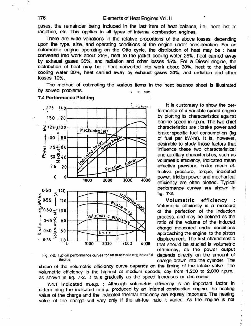
Fig. 7-2. Typical performance curves for an automatic engine at full throttle.
It is customary to show the per-formance of a variable speed engine by plotting its characteristics against engine speed in r.p.m. The two chief characteristics are : brake power and brake specific fuel consumption (kg of fuel per kW-hr). It is, however, desirable to study those factors that influence these two characteristics; and auxiliary characteristics, such as volumetric efficiency, indicated mean effective pressure, brake mean ef-fective pressure, torque, indicated power, friction power and mechanical efficiency are often plotted. Typical performance curves are shown in fig. 7-2.
V o lu m e t r ic e f f ic ie n cy Volumetric efficiency is a measure of the perfection of the induction process, and may be defined as the ratio of the volume of the induced charge measured under conditions approaching the engine, to the piston displacement. The first characteristic that should be studied is volumetric efficiency, as the power output depends directly on the amount of charge drawn into the cylinder. The
shape of the volumetric efficiency curve depends on the timing of the intake valve. The volumetric efficiency is the highest at medium speeds, say from 1,200 to 2,000 r.p.m., as shown in fig. 7-2. It falls gradually as the speed increases or decreases.
7.4.1 Indicated m.e.p. : Although volumetric efficiency is an important factor in determining the indicated m.e.p. produced by an infernal combustion engine, the heating value of the charge and the indicated thermal efficiency are equally important. The heating value of the charge will vary only if the air-fuel ratio it varied. As the engine is not

Testing of Internal Combustion Engines 177
designed for full load operation at very low speed, a poor thermal efficiency results. In general, the i.m.e.p. of an internal combustion engine follows the volumetric efficiency curve rather closely, but at low speeds it falls off a little more than does the volumetric efficiency.
7.4.2. Indicated power : For a given engine, the indicated power is directly proportional to the product of the i.m.e.p and r.p.m. At low and moderate speeds, there is a slight change in i.m.e.p. Hence, over this range, the indicated power curve is almost a straight line, the indicated power being practically proportional to the r.p.m. At higher speeds the decrease in i.m.e.p. causes the indicated power to fall away from a straight line; and at very high speeds, the i.m.e.p. falls off faster than the r.p.m. (speed) and the indicated power decreases.
7.4.3 Friction power : The friction power of a given engine is a function of the product of the frictional resistance and the r.p.m. The major portion of the engine friction in an I.C. engine is the friction between the rings and cylinder walls, and between piston and cylinder walls. With the thick oil film between them, the frictional resistance is directly proportional to the speed. Frictional power should increase faster than the speed. Test results show that this is true.
7.4.4 Brake power : The brake power is the difference between the indicated power and friction power. As the friction power increases faster than the speed, the brake power reaches a maximum value at a speed somewhat lower than that of maximum indicated power. The speed for maximum brake power is known as the peak speed of the engine. This is the speed at which automobile engines are usually rated.
7.4.5 Mechanical efficiency : Mechanical efficiency is the ratio of brake power and indicated power, or ratio of the brake power to the sum of the brake power and friction power. Since the friction power increases faster than the speed and since the brake power fails to increase as fast as speed, the mechanical efficiency must decrease as the speed increases. The decrease is gradual at low speeds, but becomes very rapid at high speeds.
7.4.6 Brake M.E.P. As it is difficult to determine accurately either the indicated m.e.p. or the indicated power for a high speed I.C. engine, the brake m.e.p. is calculated and
Fig. 7-3. Typical curves of brake specific fuel consumption and required per kW-hour on brake powermechanical efficiency for constant speed engines. basjs Brake specjfjc ^ consum p_
tion (b.s.f.c.) is inversely proportional to brake thermal efficiency. Since indicated thermal
100 0-85used instead. Brake m.e.p. is equ2l to the product of the indicated m.e.p. and mechanical efficiency. Hence, the curve for brake m.e.p. is quite similar in shape to that for the i.m.e.p., but it falls off faster at high speeds as shown in fig. 7-2.
.0-100 20 40 60 80 100 -120
Percentage of rated load
7.4.7 Torque : Torque is the turning effort produced by an engine. For a given engine, torque is a direct function of brake m.e.p. and as such, the torque curve must have the same shape as the brake m.e.p. curve.
7.4.8 Brake specific fuel con-sumption : It is the mass of a fuel
178 Elements of Heat Engines Vol. IIefficiency falls off at low speeds, the b.s.f.c. becomes relatively high. At high speeds although the indicated thermal efficiency remains high, the excessive frictional losses cause decrease in the brake thermal efficiency and increase in b.s.f.c. Although the curves (fig. 7-2) that have been discussed are those of a variable speed spark-ignition engine, the curves for a Diesel engine (compression-ignition engine) are similar.
For a constant speed engine, the curve most commonly plotted is the brake specific fuel consumption versus load, although curves of mechanical and thermal efficiencies may also be plotted as shown in fig. 7-3. For both the Diesel and spark-ignition types of engines, the brake specific fuel consumption increases at heavy loads, primarily because of the large amount of incomplete combustion that accompanies the low air-fuel ratio used, to obtain the heavy loads. A light loads, the brake fuel rates for both types of engines become rather large, primarily. because the friction power being substantially constant at a given speed, a large portion of the indicated power output is lost at light loads. Hence, much more fuel must be used per kW-hour on brake power basis at light loads.
Problem - 1 : The following observations were made during a test on a two-stroke cycle oil engine :
Cylinder dimensions - 20 cm bore, 25 cm stroke ; speed, 6 r.p.s.; effective brake drum diameter, 1.2 metres; net brke load, 440 newtons; indicated mean effective pressure, 280 kPa; fuel oil consumption, 3.6 kg/hr.; calorific value o f fuel oil, 42,500 kJ/kg; mass of jacket cooling water per hour, 468 kg; rise in temperature o f jacket cooling water, 28°C; air used per kg of fuel oil, 34 kg; temperature of air in test house, 30°C; temperature of exhaust gases, 400°C; mean specific heat of exhaust gases, 1 H.J/kg K.
Calculate : (a) the brake power, (b) the indicated power, (c) the mechanical efficiency,(d) the brake mean effective pressure, and (e) brake power fuel consumption in kg per kW-hr. Draw up a heat balance sheet in kJ/min. and as percentages of the heat supplied to the engine. Calculate also the brake thermal efficiency of the engine.
(a) Brake power = (W - S ) x R x 2 x x N watts= 440 x 0-6 x 2 x 3-14 x 6 - 9,948 watts or 9948 kW
(b) Indicated power - pm x a x I x n watts
= 13,188 watts or 13-188 kW.
(d) Brake m.e.p. = Indicated m.e.p. x mech. efficiency= 280 X 0-7541 = 211-15 kPa
(e) Fuel consumption in kg per kW-hr. on brake power basis
= 3-6 = 0-3616 kg/kW-hr.9-948
Heat supplied per minute :Heat supplied by combustion of fuel per min.
- x 42,500 = 2,550 kJ/min.
Heat expenditure per minute :

(1) Heat equivalent of brake power per min.= brake power x 60 = 9-948 x 60 = 596-88 kJ/min.
(2) Using eqn. (7.1), heat lost to jacket cooling water per min.= mass of cooling water per min. x specific heat of water x rise in
temperature of jacket cooling water468
- mw X K X (f2 - fi) - x 4-187 X 28 = 914-5 kJ/min.60(3) 1 kg of fuel combines with 34 kg of air and produces 35 kg of exhaust gases
i.e. 1 kg of fuel produces 35 kg of exhaust gases.Now, as 1 kg of fuel produces 35 kg of exhaust gases,
3*6 3a6— kg of fuel per minute will produce — x 35 = 2-1 kg of exhaust gases/min.
Using eqn. (7.2),Heat lost to exhaust gases/min. (wet)
= mass of exhaust gases/min. x specific heat of exhaust gases x (exhaust gas temp. - room temp.)
- mg X kp X (tg - tr) = 2-1 X 1 X (400 - 30) = 777 kJ/min.(4) Heat lost to radiation, errors of observation, etc. per min. (by difference)
= 2,550 - ( 596-88 + 914-5 + 777 ) = 216-62 kJ/min.
Testing of Internal Combustion Engines 179
Heat balance sheet in kJ/minuteHeat supplied/min. kJ % Heat expenditure/min. kJ %
Heat supplied by com-bustion of fuel
2,550 100 (1) Heat equivalent of brake power
(2) Heat lost to jacket cooling water
(3) Heat lost to exhaust gases (wet)
(4) Heat lost to radia-tion,errors of observa- tion.etc. (by difference)
596-88
914-5
777
261-62
23 41
35-86
30-47
10-26
Total 2,550 100 Total 2,550 100
_ . xl_ , . Heat equivalent of brake power per mm.Brake thermal efficiency = -3- r ,— r—— c— :— c------------------J Heat supplied per min.
9-948 X 60 nnnAA __= — — —— = 0-2341 or 23-41 %2,550
Problem - 2 : In a test of an oil engine running under full load conditions, the following results were obtained :
Brake power, 185 kW; Fuel consumption, 5-5 kg/hr; Calorific value of fuel oil, 43,000 kJ per kg; Inlet and outlet temperatures of cylinder circulating water, 15-5°C and 712°C respectively; Rate of flow of cylinder circulating water, 4 6 kg/min.; Inlet and outlet temperatures of water to exhaust gas calorimeter, 15-5°C and 54 4°C respectively; Rate of flow of water through calorimeter, 81 kg pei min.; Temperature o f exhaust gases leaving the calorimeter, 822eC; Room temperature, 17°C; Air-fuel ratio on mass basis, 20. Take the mean specific heat o f exhaust gases including vapour as 1005 kJ/kg K.
Draw up a heat balance sheet for the test on one minute basis and as percentages13

of the heat supplied to the engine.Heat supplied per minute :
5-5Heat supplied by combustion of fuel - — x 43,000
180 Elements of Heat Engines Vol. II
3,942 kJ/min.
Heat expenditure per minute :(1) Heat equivalent of brake power = 18-5 x 60 » 1,110 kJ/min.(2) Heat lost to cylinder jacket circulating water
= 4-6 x 4-187 x (71-2 - 15-5) - 1,072-8 kJ/min.(3) (a) Heat absorbed by water in the exhaust gas calorimeter
- 8-1 x 4-187 x (54-4 - 15-5) - 1,312-5 kJ/min.(b) Heat remaining in exhaust gases leaving the exhaust gas calorimeter
= x 21 j x 1-005 x (82-2 - 17) = 126-1 kJ/min.
Using eqn. (7.3), total heat carried away by exhaust gases (wet) = (a) + (b) = 1,312-5 + 126-1 = 1,438-6 kJ/min.
(4) Heat lost to radiation, errors of observation, etc. (by difference)= 3,942 - ( 1,110 + 1,072-8 + 1,438-6 ) = 320-6 kJ/min.
Exhaust gas inlet
Wat I outlet 5*
tater rfll— •<*C ^
LExhaust calorimeter
r p
l i r u s
:5 £ = "
Water inlet 155 C
¥ura,n Exhaust gas
Fig. 7-4. Exhaust gas calorimeter. outlet 82-2*CHeat balance sheet in kJ/minute
Heat supplied/min. kJ % Heat expenditure/min. kJ %
Heat supplied by combustion of fuel oil
3,942 100 (1) Heat equivalent ofbrake power
(2) Heat lost to jacketcooling water
(3) Heat lost to exhaust gases (wet)
(4) Heat lost to radia-tion,errors,etc.(by difference)
1,110-0
1,072-8
1,438 6
320-6
28 16
27-22
36-50
812
Total 3,942 100 Total 3,942 100-00
Note : Heat to friction = indicated power - brake power, reappears partly in the heat to jacket cooling water and partly in exhaust gases and radiation.
Problem - 3 : The following readings were taken during a test on a single-cylinder, four-stroke cycle oil engine : Cylinder bore, 20 cm; Stroke length, 35 cm; Indicated mean effective pressure, 700 kPa; Engine speed, 4 r.p.s; Fuel oil used per hour, 3-5 kg; Calorific value o f oil, 46,000 kJ/kg; Brake torque,. 450 N.m; Mass o f jacket cooling water per minute, 5 kg; Rise in temperature of jacket cooling water, 40°C; Mass of air supplied per minute, 1-35 kg; Temperature of exhaust gases, 340°C; Room temperature, 15°C; Mean specific heat o f dry exhaust gases, 1 kJ/kg K; Hydrogen in fuel, 13 5% on mass basis, kp of steam in exhaust gases, 2-3 kJ/kg K.
Calculate the mechanical and indicated thermal efficiencies and brake power fuel consumption in kg per kW-hr. Also draw up a heat balance sheet in kJ/min. and as percentages of the heat supplied to the engine.
Indicated power - pm x a x I x n watts2
= (700 X 103) X ^ X ~ X | = 15,400 watts or 15-4 kW
Brake power = (W - S) R x 2 i x W watts =* T x 2x x N watts- 450 X 2 X 3-14 X 4 - 11,304 watts or 11-304 kW
• w. . . . . . Brake power 11-304Mechanical efficiency - 7—=——5--------- = = 0-734 or 73-4%1 Indicated power 15-4
Indicated thermal efficiency - Heat equivalent of indicated power in kJ per min.Heat supplied in kJ per min.
15 4 -* -60 = 0-3443 or 34-43%
Testing of Internal Combustion Engines 181
f f x 46,000
Q.CFuel consumption in kg per kW-hr. on brake power basis = -7- —— = o-31 kg/kW-hr
11 -304Heat supplied per minute :
3 .5Heat supplied by combustion of fuel = — x 46,000 = 2,683-3 kJ/min.ouHeat expenditure per minute :(1) Heat equivalent of brake power - 11-304 x 60 = 678-24 kJ/min.(2) Heat lost to jacket cooling water = 5 x 4-187 x 40 = 837-4 kJ/min.(3) Mass of wet exhaust gases per minute
= mass of air per min. + mass of fuel per min.
= 1-35 + —| =1-4083 kg per min.
2 H2 + O2 = 2 H2O1 + 8 = 9 i.e., one kg of H2 produces 9 kg of H2OMass of H2O produced per kg of fuel burnt = 9 x H2 = 9 x 0-135 =1-215 kg per kg of fuel.Mass of H2O (steam) produced per minute = 1-215 x mass of fuel per minute
= 1-215 x — = 0 0709 kg per min.
I.e., mass of steam in wet exhaust gases = 0-0709 kg per min.Mass of dry exhaust gases per minute
= mass of w et exhaust gases/min. - mass of steam in wet exhaust gases/min.= 1-4083 - 0-0709 = 1-3374 kg.
.*. Heat lost to dry exhaust gases min. = mass of dry exhaust gases x specific heat of dry exhaust gases x ( exhaust gas temp. - room temp. )
= 1-3374 x 1 x (340 - 15) = 434-66 kJ/min.(4) Assuming that the steam in exhaust gases exists as superheated steam at
atmospheric pressure ( 1-01325 bar ) and at exhaust gas temperature,Enthalpy of 1 kg of steam = HSUp - h
= [ Hs + kp ( t sup — ts ) ] — h= [2,676-1 + 2-3(340 - 100)] - 15 x 4-187 - 3,165-3 kJ/kg
Heat lost to steam in exhaust gases per min.= ma f̂e of steam per min. x enthalpy of 1 kg of steam = 0-0709 x 3,165-3 = 224-42 kJ/min.
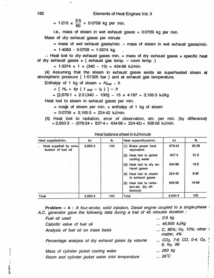
(5) Heat lost to radiation, error of observation, etc. per min. (by difference)= 2,683-3 - (678-24 + 837-4 + 434-66 + 224-42)= 508-58 kJ/min.
182 Elements of Heat Engines Vol. II3.5
Heat balance sheet in kJ/minuteHeat supplied/min. kJ % Heat expenditure/min. kJ %
Heat supplied by corrv bustion of fuel oil
2,683.3 100 (1) Brake power heat equivalent
(2) Heat lost to jacket cooling water
(3 ̂ Heat lost to dry ex-haust gases
(4) Heat lost to steam in exhaust gases
(5) Heat lost to radia-tion,etc. (by dif-ference)
678 24
837-4
434-66
224 42
508-58
25 29
31-2
16 2
836
18 95
Total 2,6833 100 Toted 2,683-3 100
Problem — 4 : A four-stroke, solid injection, Diesel engine coupled to a single-phase ii A.C. generator gave the following data during a trial of 45 minutes duration :
... 2 9 kg
... 46,900 kJ/kg
... C, 86%; H2, 10%; other i matter, 4%
... CO2, 7-6; CO, 0-4; O2, ! 6; N2. 86
... 260 kg
Fuel oil usedCalorific value of fuel oilAnalysis of fuel oil on mass basis
Percentage analysis o f dry exhaust gases by volume
Mass of cylinder jacket cooling waterRoom and cylinder jacket water inlet temperature 26°C

Testing of Internal Combustion Engines 183
Temperature of water leaving cylinder jacket ... 73°CTemperature of exhaust gases Engine speedGenerator voltage and current Efficiency of generator
290°C 250 r.p.m.440 V, *25 Amp. 92%
Soon after the test the engine was motored by the dynamo taking current from the mains : Applied voltage - 440 V; Current - 7.8 Amp.; Speed - 250 r.p.m.; Efficiency of the generator as motor - 92%
Draw up a heat balance sheet on percentage basis assuming that the steam in the exhaust gases is at atmospheric pressure (1-01325 bar). Calculate the mechanical efficiency of the engine. Take kp of dry exhaust gases as 1 kJ/kg K and kp of steam as 2-1 kJ/kg K
Heat supplied per 45 minutes :Heat supplied by combustion of fuel = 2-9 x 46,900 = 1,36,010 kJ/ 45 min.Heat expenditure per 45 minutes :
4 4 0 x 2 5(1) Brake power = — —---—— = 11-957 kWs 7 K 0-92 x 1,000Heat equivalent of brake power = 11-957 x 60 x 45 - 32,284 kJ/45 min.(2) Heat lost to jacket cooling water = 260 x 4-187(73 - 26) = 51,165 kJ/45 min.
NC(3) The mass of air supplied per kg of fuel = __ _------3 3 ( G i + C2)
where N, Ci, C2 are percentages of nitrogen, carbon dioxide and carbon monoxide by volume in exhaust gases, and C is the percentage of carbon in fuel oil on mass basis.
8 6 x 8 6Mass of air supplied per kg of fuel = — ——---- — — = 28 kg.M 33(7-6 + 0-4) aOut of the above air, oxygen used for combustion of hydrogen= 0 - 1 x 8 = 0-8 kg.
.*. Remaining air forming dry exhaust gases = 28 - 0.8 = 27-2 kgHence mass of dry products of combustion ( exhaust gases )
= 27-2 + 0-86 = 28-06 kg/kg of fuel.Mass of dry exhaust gases/45 min. = 2-9 x 28 06 = 81-4 kg/45 min.
Thus, heat lost to dry exhaust gases = 81-4 x 1 x (290 - 26) = 21,490 kJ/45 min.(4) Heat lost to steam in exhaust gases per 45 min.
= [mass of fuel/45 min x 9 Hz] x [Hs + kp (tSUp - ts) - h]= [2-9 x (9 x 0-1)] x [2,676-1 + 2-1 (290 - 100) - 26 x 4-187]= 7,741-8 kJ/45 min.
(5) Heat lost to radiation, errors of observations, etc. (obtained by difference)= 1,36,010 - ( 32,284 + 51,165 + 21,490 + 7,741-8 ) = 23,329-2 kJ/45 min.

184 Elements of Heat Engines Vol. IIHeat balance sheet in kJ per 45 minutes
Heat supplied per 45 min.
kJ % Heat expenditure per 45 min.
kJ %
Heat supplied by com-bustion of fuel oil
1,36,010 100 (1) Heat equivalent of Brake power
(2) Heat lost to jacket cooling water
(3) Heat lost to dry ex- ■ ha list gases
(4) Heat lost to steam in exhaust gases
(5) Heat lost to radia-tion,errors of observa-tion,etc. (by differe-nce)
32,284
51,165
21,490
7,741-8
23,329-2
23-74
37-62
15 80
5-69
17-15
Total 1,36,010 100 Total 1,36,010 100
_ . . . , . 440 x 7-8 x 0*92 0 . , . . .Friction power of the engine --------- ———------- = 3-157 kWI |U U U
> i . _**■ • Brake powerMechanical efficiency r\m = ;--------------- r ------------7 1 Brake power + Friction power11-957 11-957 __________
Problem - 5 : A six-cylinder, four-stroke Diesel engine has a bore to stroke ratio of 360 : 500 mm. During the trial, following results were obtained :
Mean area of the indicator diagram, 78 crrf; length of the indicator diagram, 7-5 cm; spring number, 700 kPa per cm of compression; brake torque, 14,000 N.m; speed, 8 r.p.s.; fuel consumption, 240 kg/hr; calorific value of fuel oil, 44,000 kJ/kg; jacket coolingwater used, 320 kg/minute; rise in temperature of the cooling water, 40°C; piston coolingoil (specific heat, 2.1 kJ/kg K) used, 140 kg/min., with a temperature rise of 28°C. The exhaust gases give up all their heat to 300 kg/minute of water circulating through the exhaust gas calorimeter and raises its temperature through 42°C.
Calculate the brake specific fuel consumption in kg per kW-hour and mechanical efficiency o f the engine and draw up a heat balance sheet of the engine on the basis of 1 kg of fuel oil.
7*8Indicated mean effective pressure, = pm = — x 700 * 728 kPa7*5Indicated power per cylinder = pm x a x I x n kW
= 728 x [0-7854 x (0-36)2] x 0-5 x | - 148-2 kW
Total indicated power developed by six cylinders = 148-2 x 6 = 889-2 kWBrake power = T x 2n x N = 4,000 x 2j i x 8 = 7,03,720 watts = 703-72 kW
240Brake specific fuel consumption ( B.S.F.C. ) = 7 — — = 0-341 kg/kW-hr.
,. , . , ^ . Brake power 703-72 _Mechanical efficiency - . .. . ,.^ r = QQfc - = 0-7914 or 79-14%1 Indicated power 889-2Heat supplied per kg of fuel oil :(1) Heat supplied per kg of fuel oil = 1 x 44,000 = 44,000 kJ/kg of fuel

Heat expenditure per kg of fuel oil :(1) Heat equivalent of brake power per Kg of fuel oil
= 703-72 x 60 x 240 = 10,556 kJ/kg
320 x 60(2) Mass of jacket cooling water used per kg of fuel oil = — — -— = 80 kg.
Heat lost to cylinder jacket cooling water per kg of fuel oil '= 80 x 4-187 x 40 = 13,398 kJ/kg.
140 x 60(3) Mass of piston cooling oil used per kg of fuel oil = — — = 35 kg
Heat lost to piston cooling oil per kg of fuel oil = 35 x 2-1 x 28 = 2,058 kJ/kg(4) Mass of water circulated in exhaust gas calorimeter per kg of fuel oil
300 x 60 .240 9
Heat lost to exhaust gases per kg of fuel oil = 75 x 4-187 x 42 = 13,189 kJ/kg(5) Heat lost to radiation, errors of observation, etc. per kg of fuel oil (by difference)
= 44,000 - (10,556 + 13,398 + 2,058 + 13,189) = 4,789 kJ/kg
Testing of Internal Combustion Engines 185
Heat balance sheet per kg of fuel oilHeat supplied per kg of fuel oil kJ Heat expenditure per kg of fuel oil kJ
Heat supplied by combustion of fuel oil 44,000 (1) Heat equivalent of brake power 10,566
(2) Heat lost to jacket cooling water 13,398
(3) Heat lost to piston cooling oil 2,058
(4) Heat lost to exhaust gases ( wet ) 13,189
(5) Heat lost to radiation, errors of 4,789observation, etc. (by difference)
Total 44,000 Total 44,000
Problem - 6 : A single-cylinder, four-stroke cycle gas engine o f 25 cm bore and 36 cm stroke, with hit and miss governing, was tested with the following results :
Duration of trial, one hour; net load on the brake, 1,200 newtons; effective radius of the brake wheel, 0.6 metre; total number of revolutions, 14,400; total number of explosions, 6,600; mean effective pressure from indicator diagram, 700 kPa; gas used, 13 7 m3 at normal temperature ( 0°C ) and pressure ( 760 mm Hg ); calorific value of gas at normal temperature and pressure, 20,000 kJ/m3 ; mass of cooling water passing through the jacket, 600 kg; temperature of jacket cooling water at inlet 15°C and at outlet 50°C; mass of exhaust gases, 210 kg; temperature of exhaust gases, 400°C; room temperature, 15°C; mean specific heat of exhaust gases 1 kJ/kg K.
Calculate the thermal efficiency on indicated power and brake power basis, and draw up a heat balance sheet for the test on one minute basis in kJ and as percentages of the heat supplied to the engine.
Brake power = ( W - S ) x R x 2 j i x N watts14 400= 1,200 x 0-6 x 2 x 3-14 x = 18,086 watts or 18-086 kWo.oOO
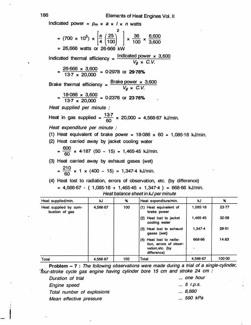
186 Elements of Heat Engines Vol.Indicated power * pm x a x I x n watts
(700 x 103) x
m 26,666 watts or 26-666 kW
2 .
TC / 2 5 \ 364 1 0 0 _
X . j-. j-J 1 0 0
6,6003,600
Indicated therm al efficiency - lndlcalf P°wef « M S 9' Vg X C.V.
26 666 x 3,600 13-7 x 20,000 - 0-2978 or 2978%
Brake thermal efficiency - Brake power x 3 , 6001 Vg X C.V.
18 086 x 3,600 13-7 x 20,000
Heat supplied per minute :13-7
0-2376 or 2376%
Heat in gas supplied60 X 20,000 - 4,566-67 kJ/min.
Heat expenditure per minute :(1) Heat equivalent of brake power - 18 086 x 60 * 1,085-16 kJ/min.(2) Heat carried away by jacket cooling water
60060 x 4-187 (50 - 15) = 1,465-45 kJ/min.
(3) Heat carried away by exhaust gases (wet) 21060 x 1 x (400 - 15) = 1,347-4 kJ/min.
(4) Heat lost to radiation, errors of observation, etc. (by difference)= 4,566-67 - ( 1,085-16 + 1,465-45 + 1,347-4 ) = 668-66 kJ/min.
Heat balance sheet in kJ per minuteHeat supplied/min. kJ % Heat expenditure/min. kJ %Heat supplied by com*
bustion of gas4,566-67 100 (1) Heat equivalent of
brake power(2) Heat lost to jacket
cooling water(3) Heat lost to exhaust
gases (wet)(4) Heat lost to radia-
tion, errors of obser-vation,etc. (by difference)
1,085-16
1,465-45
1,347-4
668-66
23-77
32-09
29-51
14.63
Total 4,566-67 100 Total 4,566 67 100-00
Problem - 7 : The following observations were made during a trial of a single-cylind6r, 'four-stroke cycle gas engine having cylinder bore 15 cm and stroke 24 cm :
Duration of trial ... one hourEngine speed ... 5 r.p.s.Total number of explosions ... 8,880Mean effective pressure ... 590 kPa
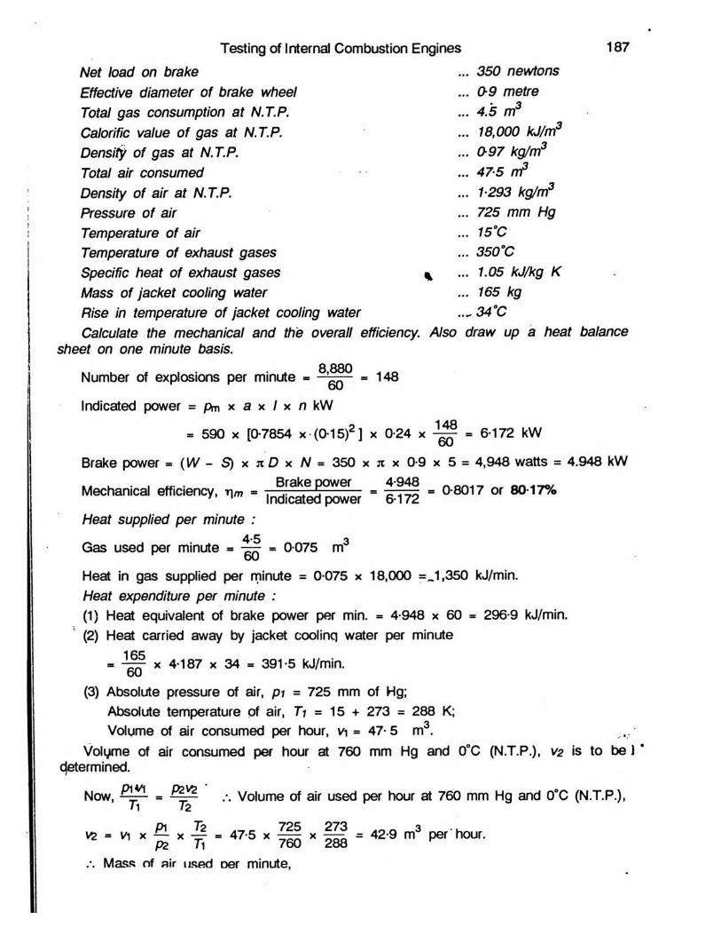
Testing of Internal Combustion Engines 187350 newtonsNet load on brake
Effective diameter of brake wheel Total gas consumption at N.T.P.Calorific value o f gas at N.T.P.Density of gas at N.T.P.Total air consumed Density of air at N.T.P.Pressure o f air Temperature of air Temperature of exhaust gases Specific heat of exhaust gases Mass of jacket cooling water Rise in temperature of jacket cooling water Calculate the mechanical and the overall efficiency. Also draw up a heat balance
sheet on one minute basis.8 880Number of explosions per minute - * - = 1 4 8
Indicated power = pm x a x / x n kW
= 590 x [0-7854 x (0-15)2 ] x 0-24 x = 6-172 kW
Brake power - (W - S ) x n D x N = 350 x n x 0-9 x 5 = 4,948 watts = 4.948 kW
Mechanical efficiency, rim
. 0-9 metre
. 4.5 m3
. 18,000 kJ/m3
. 0-97 kg/m3
. 475 rrt3
. 1293 kg/m3
. 725 mm Hg
. 15°C
. 350°C
. 1.05 kJ/kg K
. 165 kg
...34°C
, ^ P°W6r - H I ; - 0-8017 or 80-17% Indicated power 6-172Heat supplied per minute :
4-5 3Gas used per minute = — = 0-075 mDUHeat in gas supplied per minute = 0-075 x 18,000 =0,350 kJ/min.Heat expenditure per minute :(1) Heat equivalent of brake power per min. = 4-948 x 60 = 296-9 kJ/min.(2) Heat carried away by jacket coolinq water per minute
16560 x 4-187 x 34 = 391-5 kJ/min.
(3) Absolute pressure of air, p i m 725 mm of Hg;Absolute temperature of air, Ti = 15 + 273 = 288 K;Volume of air consumed per hour, v\ = 47-5 m3.
Volume of air consumed per hour at 760 mm Hg and 0°C (N.T.P.), v2 is to be J * determined.
Now, p iv i pzvz .-. Volume of air used per hour at 760 mm Hg and 0°C (N.T.P.),
V2 = v\ x — x = 47-5 x x = 42-9 m3 per'hour. PZ 11 / dU d o o
:. Mass of air used Der minute,

188 Elements of Heat Engines Vol.
/T7i = density of air at N.T.P. x v2 - 1-293 x 42-960 = 0-927 kg.
Mass of gas consumed per minute, m2 = 0-97 x 0075 = 0-0728 kg..-. Mass of exhaust gases produced per minute,mg = m j + m2 = 0-927 + 0-0728 = 0-9998 kg. 0Heat lost to exhaust gases per minute (wet)= mg x sp. heat of exhaust gases x (exhaust gas temp. - room temp.)= 0-9998 x 1-05 x (350 - 15) = 351-7 kJ/min.(4) Heat lost to radiation, errors of observation, etc. (obtained by difference) = 1,350 - ( 296-9 + 391-5 + 351-7 ) = 309-9 kJ/min.
Heat balance sheet in kJ per minuteHeat supplied/min. kJ Heat expenditure/m in. kJHeat supplied by combustion of gas 1,350 (1) Heat equivalent of brake power 296-9
(2) Heat lost to jacket cooling water 391-5
(3) Heat lost to exhaust gases ( wet ) 351 -7
(4) Heat lost to radiation, errors of 309.9observation, etc. (by difference)
Toted 1,350 Total 1,350
i, ~s . / u i i xc * v Brake power heat equivalent in kJ per hr.Overall efficiency ( brake thermal efficiency ) = ---------^ . . .------ —c------Heat supplied in kJ per hr.
4-948 x 3,600 = 0-22 or 22%4-5 x 18,000Problem - 8 : A single-cylinder, 4-stroke cycle gas engine of 20 cm bore and 38
cm stroke, with hit and miss governing, was tested with the following results :Barometer, 720 mm of Hg; Atmospheric and gas temperatures, 17°C; Gas consumption
0153 m3/minute at 8 8 mm of water above atmospheric pressure; Calorific value of gas18,000 kJ/m3 at N.T.P.; Density of gas 0.61 kg/m at N.T.P.; Hydrogen content in gas, 13% on mass basis; Air used, 145 kg per minute; Kp of dry exhaust gases, 105 kJ/kgK;
Exhaust gas temperature, 400°C; Kp of steam, 21 kJ/kg K :M.E.P. - Positive loop = 560 kPa at firing;M.E.P. - Negative loop = 26 5 kPa at firing;M.E.P. - Negative loop = 36 7 kPa at missing;
Speed, 285 r.p.m., Explosions per min-ute, 114; Brake-torque, 335 N.m; Cylinder jacket cooling water, 4 5 kg/minute; Rise in temperature of jacket cooling water, 40°C.
Calculate the percentages of the in-dicated power which are used for pumping and for mechanical friction, and draw up a percentage heat balance sheet.
The p-v diagram ( fig. 7-5 ) consists of two enclosed areas. The negative loop,
Fig. 7-5. t
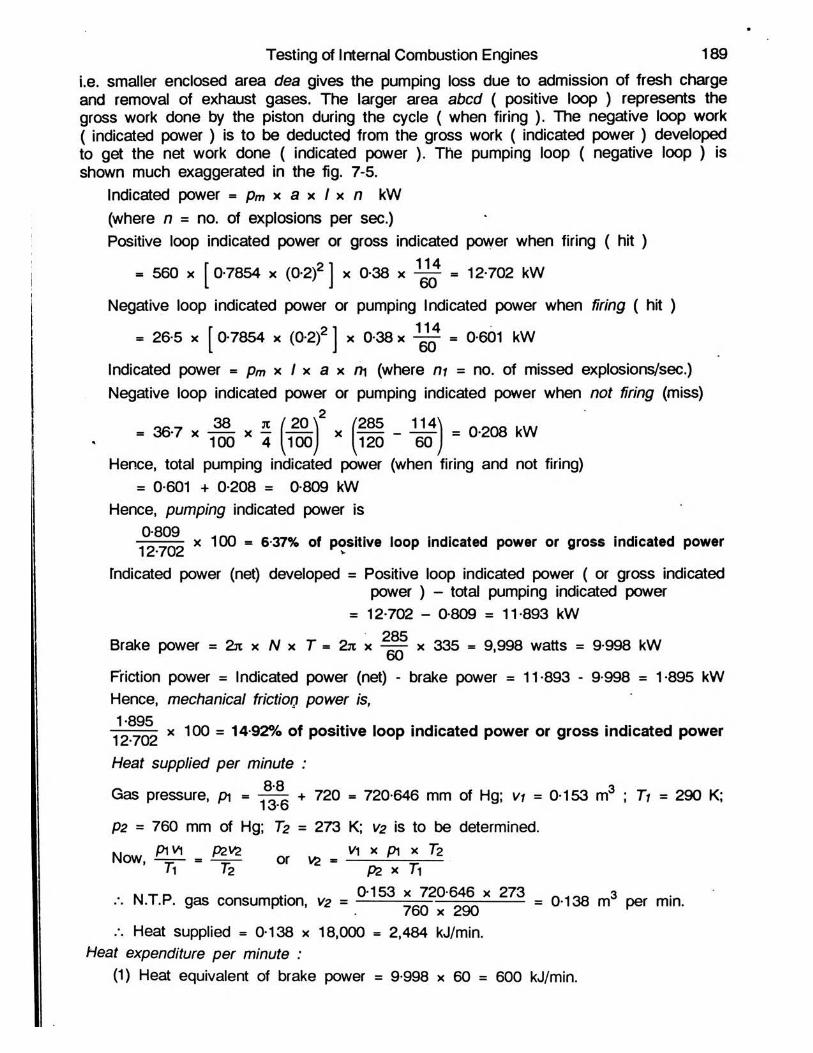
i.e. smaller enclosed area dea gives the pumping loss due to admission of fresh charge and removal of exhaust gases. The larger area abed ( positive loop ) represents the gross work done by the piston during the cycle ( when firing ). The negative loop work ( indicated power) is to be deducted from the gross work ( indicated power) developedto get the net work done ( indicated power ). The pumping loop ( negative loop ) isshown much exaggerated in the fig. 7-5.
Indicated power - pm x a x I x n kW(where n = no. of explosions per sec.)Positive loop indicated power or gross indicated power when firing ( hit )
= 560 x [ 0-7854 x (0-2)2 ] x 0-38 x ^ • 12-702 kW
Negative loop indicated power or pumping Indicated power when firing ( hit )
= 26-5 x [ 0-7854 x (0-2)2 ] x 0-38 x ~ = 0-601 kW
Indicated power = pm x I x a x m (where m = no. of missed explosions/sec.) Negative loop indicated power or pumping indicated power when not firing (miss)
= 36-7 x ^ x J (7 ^ :) x ( H I - = 0-208 kW100 4 ^100j ^120 60 jHence, total pumping indicated power (when firing and not firing)
= 0-601 + 0-208 = 0-809 kWHence, pumping indicated power is
x 100 = 6-37% of positive loop indicated power or gross indicated power 12*702 v
fndicated power (net) developed = Positive loop indicated power ( or gross indicatedpower ) - total pumping indicated power
= 12-702 - 0-809 = 11-893 kW
Brake power = 2k x N x T - 2k x —— x 335 = 9,998 watts = 9-998 kW
Friction power = Indicated power (net) - brake power = 11-893 - 9-998 = 1-895 kW Hence, mechanical friction power is,
1V 7 0 2 x 100 = 14-92% of positive loop indicated power or gross indicated power
Heat supplied per minute :g.Q _
Gas pressure, pi = —— + 720 = 720-646 mm of Hg; vi = 0-153 m ; 7j = 290 K;lO’OP2 = 760 mm of Hg; T2 = 273 K; V2 is to be determined.
Now, o, » _ .n 12 pz x 7i
N.T.P. gas consumption, V2 = " 7602x*29()X 273 = 0138 m3 min-
Heat supplied = 0-138 x 18,000 = 2,484 kJ/min.Heat expenditure per minute :
(1) Heat equivalent of brake power = 9-998 x 60 = 600 kJ/min.
Testing of Internal Combustion Engines 189
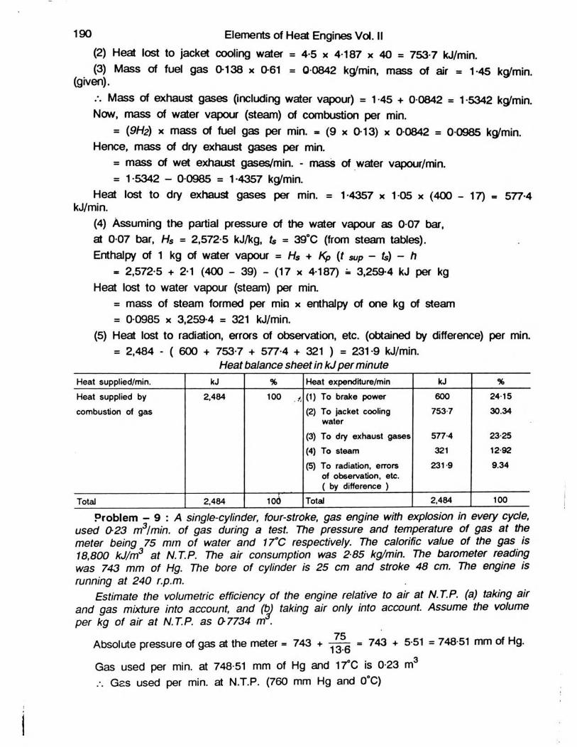
(2) Heat lost to jacket cooling water = 4-5 x 4-187 x 40 = 753-7 kJ/min.(3) Mass of fuel gas 0-138 x 0-61 = 0-0842 kg/min, mass of air = 1-45 kg/min.
(given).Mass of exhaust gases (including water vapour) = 1-45 + 0-0842 = 1-5342 kc^min.
Now, mass of water vapour (steam) of combustion per min.= (9H2) x mass of fuel gas per min. - (9 x 0-13) x 0-0842 = 0-0985 kg/min.
Hence, mass of dry exhaust gases per min.= mass of wet exhaust gases/min. - mass of water vapour/min.= 1-5342 - 0-0985 = 1-4357 kg/min.
Heat lost to dry exhaust gases per min. = 1-4357 x 1-05 x (400 - 17) - 577-4 kJ/min.
(4) Assuming the partial pressure of the water vapour as 0-07 bar, at 0-07 bar, Hs = 2,572-5 kJ/kg, ts = 39°C (from steam tables).Enthalpy of 1 kg of water vapour = Hs + Kp (t sup - ts) - h
- 2,572-5 + 2-1 (400 - 39) - (17 x 4-187) « 3,259-4 kJ per kg Heat lost to water vapour (steam) per min.
= mass of steam formed per min x enthalpy of one kg of steam = 0-0985 x 3,259-4 = 321 kJ/min.
(5) Heat lost to radiation, errors of observation, etc. (obtained by difference) per min. = 2,484 - ( 600 + 753-7 + 577-4 + 321 ) = 231-9 kJ/min.
190 Elements of Heat Engines Vol. II
Heat balance sheet in kJ per minuteHeat supplied/min. kJ % Heat expenditure/min kJ %
Heat supplied by 2,484 100 ,, (1) To brake power 600 24-15
combustion of gas (2) To jacket cooling 7537 30.34water
(3) To dry exhaust gases 577-4 23-25
(4) To steam 321 12-92
(5) To radiation, errors 231 9 9.34of observation, etc.( by difference )
Total 2,484 100 Total 2,484 100
Problem - 9 : A single-cylinder, four-stroke, gas engine with explosion in every cycle, used 0-23 m3/min. of gas during a test. The pressure and temperature of gas at the meter being 75 mm of water and 17°C respectively. The calorific value of the gas is 18,800 kJ/m3 at N.T.P. The air consumption was 285 kg/min. The barometer reading was 743 mm of Hg. The bore of cylinder is 25 cm and stroke 48 cm. The engine is running at 240 r.p.m.
Estimate the volumetric efficiency of the engine relative to air at N.T.P. (a) taking air and gas mixture into account, and (b) taking air only into account. Assume the volume per kg of air at N.T.P. as 07734 m .
75Absolute pressure of gas at the meter = 743 + = 743 + 5-51 = 748-51 mm of Hg.
Gas used per min. at 748-51 mm of Hg and 17°C is 0-23 m Gas used per min. at N.T.P. (760 mm Hg and 0°C)
3
i
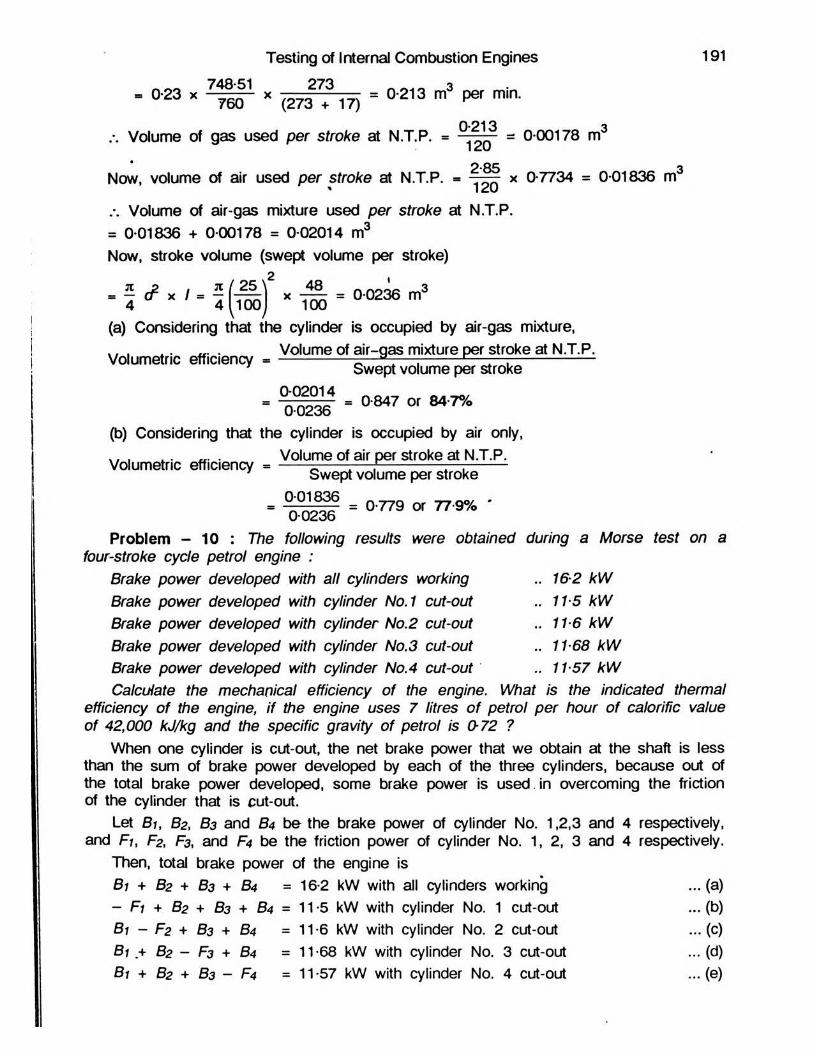
- 0,23 * x (2732? 17) = 0 213 m3 P® m ia
Volume of gas used per stroke at N.T.P. = » 0 00178 m
Now, volume of air used per stroke at N.T.P. = x 0-7734 = 0 01836 m3' 120a Volume of air-gas mixture used per stroke at N.T.P.= 0 01836 + 0 00178 = 0 02014 m3Now, stroke volume (swept volume per stroke)
- T i ' M e 3 S m >(a) Considering that the cylinder is occupied by air-gas mixture,. . . . „. . Volume of air-gas mixture per stroke at N.T.P.Volumetric efficiency = -------------- -—=-— J---------r _ ,----------------
7 Swept volume per stroke002014
- 00236 ’ a847 ° r M 7%(b) Considering that the cylinder is occupied by air only,
. Volume of air per stroke at N.T.P.Volumetric efficiency = ------=— —— P------------— --------Swept volume per stroke
= " 7" ^ = 0-779 or 77-9% *0-0236Problem - 10 : The following results were obtained during a Morse test on a
four-stroke cycle petrol engine :Brake power developed with all cylinders working .. 1&2 kWBrake power developed with cylinder No.1 cut-out .. 115 kWBrake power developed with cylinder No.2 cut-out m 116 kWBrake power developed with cylinder No.3 cut-out .. 11 68 kWBrake power developed with cylinder No.4 cut-out .* 1157 kWCalculate the mechanical efficiency of the engine. What is the indicated thermal
efficiency of the engine, if the engine uses 7 litres o f petrol per hour of calorific value of 42,000 kJ/kg and the specific gravity of petrol is 0-72 ?
When one cylinder is cut-out, the net brake power that we obtain at the shaft is less than the sum of brake power developed by each of the three cylinders, because out of the total brake power developed, some brake power is used , in overcoming the friction of the cylinder that is cut-out.
Let Bi, B2, B3 and 64 be the brake power of cylinder No. 1,2,3 and 4 respectively, and Fu F2, F3, and F4 be the friction power of cylinder No. 1, 2, 3 and 4 respectively.
Then, total brake power of the engine isB1 + B2 + B3 + 64 =16-2 kW with all cylinders working ... (a)- F1 + B2 + B3 + B4 = 11-5 kW with cylinder No. 1 cut-out ... (b)B1 - F2 + B3 + B4 = 11-6 kW with cylinder No. 2 cut-out ...(c)B1 + B2 - F3 + B4 m 11-68 kW with cylinder No. 3 cut-out ... (d)B1 + B2 + B3 - F4 =11 -57 kW with cylinder No. 4 cut-out ... (e)
Testing of Internal Combustion Engines 191

Subtracting by turn (b), (c), (d) and (e) from (a), we get,B i + F i = 16*2 — 11*5 = 4-70 kW Indicated poweriB2 + F2 = 16*2 — 11-6 = 4-60 kW Indicated power2B3 + F3 = 16-2 — 11*68 = 4*52 kW Indicated powersB4 + F4 = 16*2 — 11*57 = 4*63 kW Indicated powe.r4
192 Elements of Heat Engines Vol. II
Total indicated power developed = 18*45 kW
Mechanical efficiency, - i f ! " 0878 “ 878,4
Indicated thermal efficiency. ,,, - ~ 3,6° °
18*45 x 3,600 _ 0.3138 „ 31 38%(7 x 0-72) x 42,000 T u to ria l-7
1. Delete the phrase which is not apfdicable in the following statements :(i) Indicated power of an I.C. engine is greater/smaller than brake power.
, Brake power , Indicated power(in Mechanical efficiency of an engine is -— \ ------------------ / —- —- --------Indicated power Brake power
(iii) Indicated power of an I.C. engine is measured by an indicator / a dynamometer.(iv) Brake power of an I.C. engine is measured by an indicator / a dynamometer.(v) Morse test enables us to find the indicated power of a single-cylinder/a multi-cylinder I.C. engine without
using an indicator.N(vi) Number of cycles per min. in case of a four-stroke cycle, I.C. engine is equal to — / N, where N is
r.p.m. of the engine.(vii) In case of a supercharged I.C. engine, the pressure during the suction stroke is higher/lower than the
existing atmospheric pressure.(viii) The quantity of burnt gases left in the two-stroke cycle I.C. engine cylinder is more/less than that left
in the four-stroke cycle engine cylinder.(ix) The warm-up performance of an air-cooled I.C. engine is poor/good as compared to a water-cooled
engine.(x) For an I.C. engine, friction power increases/decreases with increase in the speed of the engine.
I Delete : (i) smaller, (ii) P°Ver, (iii) a dynamo-1 Brake powermeter, (iv) an indicator, (v) a single-cylinder, (vi) N, (vii)lower, (viii) less, (ix) poor, (x) decreases ]
2. Fill in the blanks in the following statements :(i) The ratio of brake power to indicated power of an I.C. engine is known as _______ efficiency.(ii) Two-stroke cycle I.C. engine gives one working stroke for every _______ revolution of the crankshaft.(iii) Complete actual indicator diagram of an I.C. engine consists o f _______ loops.(iv) In Diesel engines due to higher compression ratio, the temperature at the end of compression is
sufficient to _______ the fuel oil which is injected at the end of compression stroke.(v) In petrol engine using fuel having fixed octane rating, increese in compression ratio will _̂______ the
knocking tendency.[ (i) mechanical, 09 one, (iii) two, (iv) ignite, (v) increase j
3. Indicate the correct answer by selecting the proper phrase in the following :(i) More test is used to determine the mechanical efficiency of
(a) single-cylinder S.I. engine, (b) single-cylinder C.l. engine, (c) multi-cylinder I.C. engine.(ii) An I.C. engine will develop maximum torque when rt :
(a) develops maximum power, (b) runs at maximum speed, (c) runs at speed lower than that at which maximum power is developed.
(iii) For part load operation,

Testing of Internal Combustion Engines 193(a) C.l. engine is economical, (b) S.I. engine is economical, (c) both of the above engines are equally economical, (d) none of the above.
(iv) The automobile engines generally utilise batteries having voltage of :(a) 3 V, (b) 6 V, (c) 12 V, (d) 24 V. '
(v) In a Diesel engine, fi'ai injection pressure required is approximately :(a) 25 bar, (b) 100 bar, (c) 500 bar, (d) 1,000 bar.
(vi) For same power and same speed, the flywheel of a four-stroke cycle I.C. engine as compared totwo-stroke cycle I.C. engine will be :
\a) smaller, (b) bigger, (c) of the same size.(vii) For a four-stroke cycle I.C. engine there is :
(a) one power stroke for every one revolution of the crankshaft,(b) one power stroke for every two revolutions of the crankshaft,(c) one power stroke for every four revolutions of the crankshaft,(d) one power stroke for every half revolution of the crankshaft
(viii) Brake specific fuel consumption of a Diesel engine is generally :(a) less than that of a petrol engine,(b) more than*that of a petrol engine,(c) equal to that of a petrol engine,(d) unpredictable.
fix) In petrol engines using petrol of fixed octane number, i.x.ease in compression ratio will :(a) increase the knocking tendency,(b) decrease the knocking tendency,(c) have no effect on the knocking tendency.
(x) A petrol engine develops maximum power when it is supplied with air-fuel ratio of :(a) 17.5 to 18.5, (b) 16 to 17, (c) 12.5 to 13-5, (d) 10-5 to 11-5
[ (0 c, (ii) c, (iii) a, (iv) c, (v) b, (vi) b, (vii) b, (viii) a, (ix) a, (x) c ]4. Describe briefly how you would conduct the indicated power test on a small I.C. engine, listing clearly all
the observations you would take.The following observations were recorded during a trial of a four-stroke cycle, single-cylinder oil
engine : Duration of trial, 30 min.; Oil consumption, 5.5 litres; Calorific value of oil, 42,000 kJ/kg; Specific gravity of oil, 0.8; Average area of the indicator diagram, 8-4 cm2; Length of indicator diagram, 8-4 cm; Indicator spring scale, 550 kPa/cm; Brake bad, 1,700 newtons; Spring balance reading, 200 newtons; Effective brake wheel diameter, 1-5 metres; Speed, 200 r.p.m.; Cylinder diameter, 30 cm; Stroke,. 45 cm; Jacket cooling water, 11 kg per minute; Temperature rise of cylinder jacket cooling water, 36*C.
Calculate : (a) the indicated power, (b) the brake power, (c)' the mechanical efficiency, (d) the specific fuel consumption in kg/kW-hr. based on brake power, and (e) the indicated thermal efficiency.
Draw up a heat balance sheet for the test on one minute basis in kJ.I (a) 29-158 kW; (b) 23 562 kW; (c) 80-11% ; (d) 0-372 kg per kW-hr.; (e) 28-4% ]
Heat supplied per min. kJ Heat expenditure/mifl. kJHeat supplied by combustion of fuel 6,160 (1) To Brake power
(2) To Jacket cooling water
(3) To exhaust,radiation,errors of observation,etc. (by difference)
1,413.7
1,658-1
3,088-2
Total 6,160 Total 6,160-05. Describe briefly how you would conduct the brake power test on a small I.C. engine, listing clearly all the
observations you would take.During the trial of a single-cylinder, four-stroke cycle oil engine, the following results were obtained : Cylinder diameter, 20 cm; Stroke, 40 cm; Indicated mean effective pressure, 600 kPa; Brake-torque, 415 N.m; Speed, 250 r.p.m.; Oil consumption, 5-25 litres per hour; Specific gravity of oil, 0-8; Calorific value of the fuel oil, 47,500 kJ/kg; Jacket cooling water, 4-5 kg per minute; Rise in temperature of jacket cooling water, 50*C; Air used per kg of oil, 31 kg; Temperature of exhaust gases, 400*C, Room temperature, 20*C; M6an specific heat of exhaust gases, 1-005 kJ/kg K.Calculate, the indicated power, the brake power and the brake mean effective pressure and draw up a
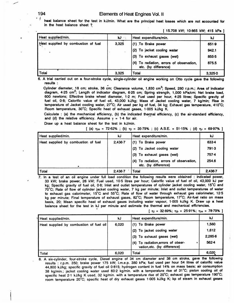
heat balance sheet for the test in kJ/min. What are the principal heat losses which are not accounted for in the heat balance sheet ?.
__________________________________________ [ 15.708 kW; 10-865 kW; 415 kPa J
194 Elements of Heat Engines Vol. II
Heat supplied/min. ia .. Heat expenditure/min. kJI^dat supplied by combustion of fuel 3,325 (1) .To Brake power 651-9
' . (2) To jacket cooling water 942.1
(3) To exhaust gases (wet) 855-5
(4) To radiation, errors of observation, 875.5etc. (by difference)
Total 3,325 Total 3,325-06 . A trial carried out on a four-stroke cycle, single-cylinder oil engine working on Otto cycle gave the following
results :Cylinder diameter, 18 cm; stroke, 36 cm; Clearance volume, 1,830 cm3; Speed, 280 r.p.m.; Area of indicator diagram, 4-25 cm8; Length of indicator diagram, 6-25 cm; Spring strength, 1,000 kPa/cm; Net brake lo600 newtons; Effective brake wheel diameter, 1-2 m; Fuel used per hour, 4-25 litres; Specific gravity offuel oil, 0-8; Calorific value of fuel oil, 43,000 kJ/kg; Mass of Jacket cooling water, 7 kg/min; Rise in temperature of Jacket cooling water, 27*C; Air used per kg of fuel, 34 kg; Exhaust gas temperature, 410*C; Room temperature, 30*C; Specific heat of exhaust gases, 1-005 kJ/kg K.Calculate : (a) the mechanical efficiency, (b) the indicated thermal efficiency, (c) the air-standard efficiency,and (d) the relative efficiency. Assume y = 1-4 for air.Draw up a heat balance sheet for the test in kJ/min.
I (a) T)m = 72-62% ; (b) t)/ = 35-79% ; (c) A.S.E. = 51-15% ; (d) t|r = 69-97% J
Heat supplied/min. kJ Heat expenditure/min. kJ
Heat supplied by combustion of fuel 2,436-7 (1) To Brake power 633-4
(2) To Jacket cooling water 791-3
(3) To exhaust gases (wet) 757-4
(4) To radiation, errors of observation, 254.6. etc. (by difference)
Total 2,436-7 Total 2,4367
7. In a test of an oil engine under full load condition the following results were obtained : indicated power, 33 kW; brake power, 26 kW; Fuel used, 10-5 litres per hour; Calorific value of fuel of oil, 43,000 kJ per kg; Specific gravity of fuel oil, 0-8; Inlet and outlet temperatures of cylinder jacket cooling water, 15*C and 70*C; Rate of flow of cylinder jacket cooling water, 7 kg per minute; Inlet and outlet temperatures of water to exhaust gas calorimeter, 15*C and 55*C; Rate of flow of water through exhaust gas calorimeter, 12-5 kg per minute; Final temperature of exhaust gases, 82*C; Room temperature, 17*C; Air-fuel ratio on mass basis, 20; Mean specific heat of exhaust gases including water vapour, 1-005 kJ/kg K. Draw up a heat balance sheet for the test in kJ per minute and estimate the thermal and mechanical efficiencies.
[ 11/ = 32-89%; t\b = 2591%; rjm = 78-79% ]
Heat supplied/min. kJ Heat expenditure/min. kJ
Heat supplied by combustion of fuel oil 6,020 (1) To Brake power(2) To jacket cooling water
(3) To exhaust gases (wet)
(4) To radiation,errors of obser- • vation.etc. (by difference)
1,560
1,612
2,285-6562-4
Total 6,020 Total 6,020•8 . A six-cylinder, four-stroke cycle, Diesel engine of 34 cm diameter and 38 cm stroke, gave the following
results : r.p.m. 350; brake power 175 kW; i.m.e.p. 380 kPa; fuel used per hour 54 litres of calorific value 44,800 kJ/kg; specific gravity of fuel oil 0-815; hydrogen content in fuel 14% on mass basis; air consumption 38 kg/min.; jacket cooling water used 60-2 kg/min. with a temperature rise of 31*C; piston cooling oil of specific heat 2-1 kJ/kg K used, 32 kg/min. with a temperature rise of 20*C; exhaust gas temperature 190*C; room temperature 20*C; specific heat of dry exhaust gases 1-005 kJ/kg K; kp of steam in exhaust gases

Testing of Internal Combustion Engines 1952 kJ/kg K; partial pressure of steam in exhaust gases 0-07 bar. Calculate the mechanical efficiency of the engine and draw up a heat balance sheet in kJ per miqute indicating, the items which may include friction losses.
[ rim = 76-8%
Heat supplied/min. kJ Heat expenditure/min. kJ
Heat supplied by combustion of fuel 32,860 . (1) To brake power
* (2) To jacket cooling water
* (3) To piston cooling oil
* (4) To dry exhaust gases
* (5) To steam in exhaust gases
* (6) To radiation .errors of observation,etc. (by difference)
10,500.0
7,813-8
1,344-0
6,460-4
2,579-3
4,162-5
Total 32,860 Total 32,860
* These items may include friction. ]9 . A four-stroke cycle gas engine has a cylinder diameter of 27 cm and piston stroke of 45 cm. The effective
diameter of the brake wheel is 1 -62 metres. The observations made in a test of the engine were as follows:Duration of test 40 minutes; Total no. of revolutions 8,080; Total no of explosions 3,230; Net load on thebrake 920 newtons; Indicated mean effective pressure 575 kPa; Gas used 7-7 m3 ; Pressure of gas at meter 130 mm of water above atmospheric pressure; Gas temperature 15’C; Height of barometer 750 mm of Hg; Calorific value’ of gas, 19,500 kJ/m3 at normal temperature ( 0’C ) and pressure ( 760 mm Hg);Mass of jacket cooling water 183 kg; Rise in temperature of jacket cooling water 50*C.
Calculate the indicated power, brake power and draw up a heat balance sheet for the test in kj per minute.{ 19-938 kW; 15.764 kW ]
Heat supplied/min. kJ Heat expenditure/min. kJ
Heat supplied by combustion of gas 3,556 8 (1) To brake power
(2) To jacket cooling water
(3) To exhaust,radiation,errors of observation,etc. (by difference)
945-8
957-8
1,653-2
Total 3,5568 Total 3,556 8t— .....■- - ........................................ ... . . ... *310. The following results were obtained in a test on a gas engine : Gas used 0-125 m per minute at N.T.P.;
Calorific value of gas 16,700 kJ/m3 at N.T.P.; Density of gas 0-64 kg per m3 at N.T.P.; Air used 1-52 kg per minute; Specific heat of exhaust gases 1-005 kJ/kg K; Temperature of exhaust gases 397*C; Room temperature 17*C; Jacket cooling water per minute 6 kg; Rise in temperature of Jacket cooling water 26’C; Indicated power 9-51 kW; Brake power 7-5 kW. Calculate the mechanical efficiency of the engine and draw up a heat balance sheet for the trial on one minute basis in kJ.
[ r»m = 78 95% J
Heat supplied/min. kJ Heat expenditure/min. kJ
Heat supplied by combustion of gas 2,087-5 (1) To Brake power 450
(2) To jacket cooling water 653.2
(3) To exhaust gases (wet) 611
(4) To radiation, errors of observation, 373.3etc. (by difference)
Total 2,087-5 Total 2,087-511. Describe briefly the method of determining the indicated power of a multi-cylinder petrol engine by cutting
out one cylinder at a time. State the assumptions made.A four-cylinder, four-stroke petrol engine is running on a brake having a radius of 1 metre. When all the four cylinders are firing, the r.p.m. is 1,400. The net brake load is 145 newtons. When spark plug of each cylinder is short circuited in turn, the net loads on the brake are 100, 103, 102 and 99.5 newtons respectively. The speed is maintained constant throughout the test. Estimate the indicated power and mechanical efficiency of the engine when all the cylinders are firing. If the cylinder bore is 9 cm and stroke is 12 cm, what is
14

196 Elements of Heat Engines Vol. IIbrake mean effective pressure ? [ 25-73 kW; 82-65% ; 596-3 kPa ]
12. During a trial on a single-cylinder oil engine having cylinder diameter of 30 cm., stroke 45 cm, and workingon the four-stroke cycle, the following observations were made :Duration of trial one hour; total fuel oil used 8-1 kg; calorific value of fuel oil 44,800 kJ/kg; total no. ofrevolutions 12,600; mean effective pressure 690 kPa; net load on the brake 1,550 newtons; diameter ofthe brake wheel drum 1-78 metres; thickness of the brake belt 2 cm; jacket cooling water circulated 550 litres; inlet temperature of cooling water 16*C; outlet temperature of cooling water 61 *C. Estimate the indicated thermal efficiency and brake thermal efficiency of engine. Draw up a percentage heat balance sheet for the trial.
I i]i = 38-1%; T)6 = 30-34% J
Heat supplied per minute kJ % Heat expenditure/min. kJ %Heat supplied by
combustion of fuel oil6,048 100 (1) To brake power
(2) To jacket cooling water
(3) To exhaust,radiation, errors of observa-tions,etc. (by difference)
1.839.7
1.727.7
2,480-6
30.41
28.56
41-03
Total 6,048 100 Total 6,048 100
13. A trial of one hour duration on a petrol engine gave the following results :Brake power 15 kW; Petrol consumption 6-4 litres; Specific gravity of petrol 0-74; Hydrogen content in
petrol 15% on mass basis; Calorific value of petrol 44,400 kJ/kg; Fuel air-ratio 1 : 1 5 ; Temperature of exhaust gases 415*C; Room temperature 27*C; Specific heat of dry exhaust gases 1-005 kJ/kg K; Partial pressure of steam in exhaust gases 0-07 bar; Kp of steam 2-1 kJ/kg K; Mass of water passing through the cylinder jackets 270 litres; Rise in temperature of jacket cooling water 50*C.
At the end of the trial the engine was motored and the input power was 4 kW. Calculate the mechanical efficiency of engine and draw up a heat balance sheet for the trial on one minute basis and as percentage of the heat supplied to the engine.
[i)m = 78-95% ]
Heat supplied/min. kJ % Heat expenditure/min. kJ %
Heat supplied by
combustion of fuel oil 3,504-6 100
(1) To brake power
(2) To jacket cooling water
(3) To dry exhaust gases(4) To steam in exhaust
gases(5) To radiation,errors of
observation, etc.(by difference)
900
942-1
450-83476
864-1
25 68
26 88
1286992
24 66
Total 3,504-6 100 Total 3,5046 100
14. A single-cylinder, four-stroke cycle gas engine has a bore to stroke ratio of 250/380 mm. During the trial the following results were noted :
Duration of trial 60 minutes; Effective brake load 1,300 newtons: Effective circumference of the brake wheel 3-8 metres; Total no. of revolutions 13,500; Total no. of explosions 6,000; Indicated m.e.p. 700 kPa; Total fuel gas used 16 m3; Temperature of fuel gas 15‘C; Pressure of fuel gas above atmospheric pressure 200 mm of water; Barometer reading 742 mm of Hg; Calorific value of fuel gas at N.T.P. (0*C and 760 mm of Hg) 20,500 kJ/m3; Density of fuel gas at N.T.P. 0 8 kg/m3; Hydrogen content in fuel gas on mass basis 14%; Total mass of air used 210 kg; Exhaust gas temperature 400’ C: Specific heat of dry exhaust gases 1 005 kJ/kg K; Kp of steam 2-1 kJAg K; Total mass of cylinder jacket cooling water 600 kg: Rise in temperature of jacket cooling water 35’C.
Draw up a heat balance sheet on one minute basis and as percentages of the heat supplied to the engine, assuming that the steam in the exhaust gases is at atmospheric pressure. Also calculate the indicated power, brake power and mechanical efficiency of the engine.
[ 21 762 kW; 18-525 kW; 85-13 %)

Testing of Internal Combustion Engines 197
Heat supplied/min. kJ % Heat expenditure/min. kJ %
Heat supplied by
combustion of gas 5,160 100
(1) To brake power
(2) To jacket cooling water
(3) To dry exhaust gases(4) To steam in exhaust
gases
(5) To radiation,errors of observation, etc.(by difference)
1,111-5
1,465-5
1,334
8226
426-4
21-54
28-41
25 85
15-94
826
Total 5,160 100 Total 5,160 100
15. The following observations were made during a trial of a single-cylinder, four-stroke cycle gas engine having cylinder diameter 18 cm and stroke 24 cm :
Duration of trial one hour; Total number of revolutions 18,000; Total number of explosions 8,800; i.m.e.p. 590 kPa; Net load on the brake wheel 400 newtons; Effective diameter of brake wheel 1 metre; Total gas used at N.T.P. 4-5 m3 •Calorific value of gas at N.T.P. 18,800 kJ/m3; Density of gas at N.T.P. 0-96 kg/m3; Total air used 71-25 m ; Pressure of air 720 mm of Hg; Temperature of air 15*C; Density of air at N.T.P. 1-293 kg/m3; Temperature of exhaust gases 350*C; Room temperature 15*C; Specific heat of exhaust gases1-005 kJ/kg K; Total mass of cylinder jacket cooling water 160 kg; Rise in temperature of jacket cooling water 35*C.
Calculate the mechanical efficiency and indicated thermal efficiency of the engine. Also draw up a heat balance sheet in kJ on one minute basis.
[ rim = 70-68%; T)/- 37-83% ]
Heat supplied./min. kJ Heat expenditure/min. kJ
Heat supplied by (1) To brake power 3770
combustion of gas 1,410 (2) To jacket cooling water 3908
(3) To exhaust gases (wet) 488 5
(4) To radiation,errors of 153-7observation, etc. (by difference)
Total 1,410 Total 1,410-0
16. The following reading were taken during a test on single-cylinder, four-stroke cycle oil engine :
Cylinder diameter
Stroke length
Gross i.m.e.p.
Pumping i.m.e.p.
Engine speed
Net load on the brake
Effective diameter of the brake
Fuel oil uSed per hour
Calorific value of fuel oil
Rate of jacket cooling water per minute
Temperature rise of jacket cooling water
Mass of air supplied per kg of fuel oil
Temperature of exhaust gases
Room temperature
Hydrogen content in fuel on mass basis
Partial pressure of steam in exhaust gases
. 280 mm
. 425 mm
.. 724 kPa
. 40 kPa
. 200 r.p.m.
. 1,300 newtons
. 1,6 meters
. 9 kg
. 42,000 kJ/kg
. 11 kg
. 36*C
■ 35 kg
. 375‘C
. 15*C
. 14%
. 0 07 bar
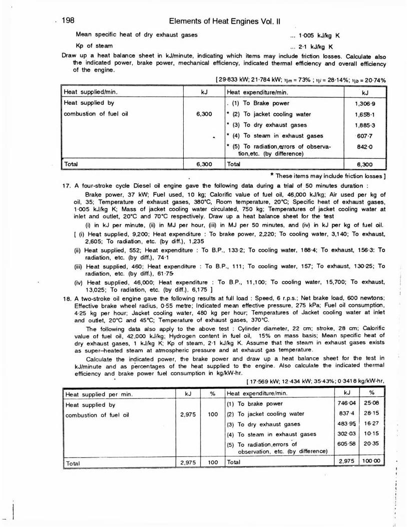
Mean specific heat of dry exhaust gases ... 1 005 kJ/kg K
Kp of steam ... 2-1 kJ/kg KDraw up a heat balance sheet in kJ/minute, indicating which items may include friction losses. Calculate also
the indicated power, brake power, mechanical efficiency, indicated thermal efficiency and overall efficiency of the engine.
[29-833 kW; 21-784 kW; i|m = 73% ; i|/= 28-14%; »u> = 20-74%
198 Elements of Heat Engines Vol. II
IHeat supplied/min. kJ Heat expenditure/min. kJHeat supplied by
combustion of fuel oil 6,300
. (1) To Brake power
* (2) To jacket cooling water
* (3) To dry exhaust gases
* (4) To steam in exhaust gases
* (5) To radiation,errors of observa-tion.etc. (by difference)
1,306-9
1,658-1
1,885-3
607-7
842-0 ;
Total 6,300 Total 6,300
* These items may include friction losses ] 17. A four-stroke cycle Diesel oil engine gave Ihe following data during a trial of 50 minutes duration :
Brake power, 37 kW; Fuel used, 10 kg; Calorific value of fuel oil, 46,000 kJ/kg; Air used per kg of oil, 35; Temperature of exhaust gases, 380°C, Room temperature, 20°C; Specific heat of exhaust gases,1-005 kJ/kg K; Mass of jacket cooling water circulated, 750 kg; Temperatures of jacket cooling water at inlet and outlet, 20SC and 70°C respectively. Draw up a heat balance sheet for the test
(i) in kJ per minute, (ii) in MJ per hour, (iii) in MJ per 50 minutes, and (iv) in kJ per kg of fuel oil.[ (i) Heat supplied, 9,200; Heat expenditure : To brake power, 2,220; To cooling water, 3,140; To exhaust,
2,605; To radiation, etc. (by diff.), 1,235(ii) Heat supplied, 552; Heat expenditure : To B.P., 133-2; To cooling water, 188-4; To exhaust, 156-3: To
radiation, etc. (by diff.), 74-1(iii) Heat supplied, 460; Heat expenditure : To B.P., 111; To cooling water, 157; To exhaust, 130-25; To
radiation, etc. (by diff.), 61-75(iv) Heat supplied, 46,000; Heat expenditure : To B.P., 11,100; To cooling water, 15,700; To exhaust,
13,025; To radiation, etc. (by diff.), 6,175 ]18. A two-stroke oil engine gave the following results at full load : Speed, 6 r.p.s.; Net brake load, 600 newtons;
Effective brake wheel radius, 0-55 metre; Indicated mean effective pressure, 275 kPa; Fuel oil consumption, 4-25 kg per hour; Jacket cooling water, 480 kg per hour; Temperatures of Jacket cooling water at inletand outlet, 20°C and 45°C; Temperature of exhaust gases, 370°C.
The following data also apply to the above test : Cylinder diameter, 22 cm; stroke, 28 cm; Calorificvalue of fuel oil, 42,000 kJ/kg; Hydrogen content in fuel oil, 15% on mass basis; Mean specific heat ofdry exhaust gases, 1 kJ/kg K; Kp of steam, 2-1 kJ/kg K. Assume that the steam in exhaust gases exists as super-heated steam at atmospheric pressure and at exhaust gas temperature.
Calculate the indicated power, the brake power and draw up a heat balance sheet for the test in kJ/minute and as percentages of the heat supplied to the engine. Also calculate the indicated thermal efficiency and brake power fuel consumption in kg/kW-hr.
[ 17-569 kW; 12-434 kW; 35-43%; 0 3418 kg/kW-hr,
Heat supplied per min. kJ % Heat expenditure/min. kJ %
Heat supplied by
combustion of fuel oil 2,975 100
(1) To brake power(2) To jacket cooling water(3) To dry exhaust gases(4) To steam in exhaust gases(5) To radiation,errors of
observation, etc. (by difference)
746-04
837-4
483 95 302 03
605 58
25-08
2 8 ,5 16 27
10-15
2035
Total 2.975 100 Total 2,975 100-00