testing cert # 2786 - fccid.io · testing cert # 2786.01 motorola penang adv. comm. laboratory fcc...
TRANSCRIPT

Report Template Document Number: FCD-0084 Report ID: 02815-RF-00072 Report Template Revision Number: Rev. B FCC ID: AZ489FT7066 IC: 109U-89FT7066
Page 1 of 40
TESTING CERT # 2786.01 MOTOROLA PENANG ADV. COMM. LABORATORY FCC TEST REPORT Motorola Solutions Malaysia Sdn Bhd Report Revision : Rev.B Innoplex Plot 2A, Medan Bayan Lepas, Mukim 12 S.W.D, 11900 Bayan Lepas, Penang, Malaysia. Date/s Tested : 12-JAN-2017 - 20-NOV-2017 Report Issue Date : 20-NOV-2017 Manufacturer/Location : Motorola Solutions Malaysia Sdn Bhd Requestor : HONG YA LI Product Type : Portable Model Number : AAH56JDN9RA1AN Frequency Band : 136-174 MHz Low / Max RF Output Power : 1 Watts / 6 Watts Applicant Name : Motorola Solutions Malaysia Sdn Bhd Applicant Address : Innoplex Plot 2A, Medan Bayan Lepas,
Mukim 12 S.W.D, 11900 Bayan Lepas, Penang, Malaysia
FCC Registrations IC Registrations
: :
772092 109AK
The equipment was tested accordance to the requirement listed below:
(LMR ) FCC 47 CFR Part 22 / 74
PASS
This report shall not be reproduced without written approval from an officially designated representative of the Motorola Penang Adv. Comm. Laboratory. The results and statements contained in this report pertain only to the device(s) evaluated.
Prepared By: Approved By:
_________________________ _________________________ SONG ZHI WEI VINCENT FOONG Test Personnel Responsible Engineer

Report Template Document Number: FCD-0084 Report ID: 02815-RF-00072 Report Template Revision Number: Rev. B FCC ID: AZ489FT7066 IC: 109U-89FT7066
Page 2 of 40
Table of Contents Report Revision History ......................................................................................................................................... 3
1.0 General Information .................................................................................................................................... 4
2.0 Summary of Test Results ............................................................................................................................ 5
3.0 Measurement Uncertainty ........................................................................................................................... 5
4.0 Equipment List ............................................................................................................................................ 6
5.0 Test Condition ............................................................................................................................................. 7
5.1. Transmitter Test Conditions ................................................................................................................... 7
6.0 Transmitter Test Parameters ....................................................................................................................... 8
6.1. RF Output Power .................................................................................................................................... 8 6.1.1. Test Setup........................................................................................................................................ 8 6.1.2. Test Result ...................................................................................................................................... 8
6.2. Frequency Stability ................................................................................................................................. 9 6.2.1. Test Setup........................................................................................................................................ 9 6.2.2. Test Result ...................................................................................................................................... 9 6.2.3. Test Limit ........................................................................................................................................ 9
6.3. Audio Frequency Response .................................................................................................................. 10 6.3.1. Test Setup...................................................................................................................................... 10 6.3.2. Test Result .................................................................................................................................... 10 6.3.3. Test Limit ...................................................................................................................................... 10
6.4. Audio Low Pass Filter Response .......................................................................................................... 11 6.4.1. Test Setup...................................................................................................................................... 11 6.4.2. Test Result .................................................................................................................................... 11 6.4.3. Test Limit ...................................................................................................................................... 12
6.5. Modulation Limiting ............................................................................................................................. 13 6.5.1. Test Setup...................................................................................................................................... 13 6.5.2. Test Result .................................................................................................................................... 13 6.5.3. Test Limit ...................................................................................................................................... 13
6.6. Occupied Bandwidth ............................................................................................................................. 14 6.6.1. Test Setup (Analog) ...................................................................................................................... 14 6.6.2. Test Result (Analog) ..................................................................................................................... 14 6.6.3. Test Setup (Digital) ....................................................................................................................... 16 6.6.4. Test Result (Digital) ...................................................................................................................... 17 6.6.5. Test Limit ...................................................................................................................................... 18
6.7. Band Edge Conducted Spurious Emission (Part 22) ............................................................................ 19 6.7.1. Test Setup (Analog) ...................................................................................................................... 19 6.7.2. Test Result (Analog) ..................................................................................................................... 20 6.7.3. Test Setup (Digital) ....................................................................................................................... 22 6.7.4. Test Result (Digital) ...................................................................................................................... 23 6.7.5. Test Limit ...................................................................................................................................... 23

Report Template Document Number: FCD-0084 Report ID: 02815-RF-00072 Report Template Revision Number: Rev. B FCC ID: AZ489FT7066 IC: 109U-89FT7066
Page 3 of 40
6.8. Transient Frequency Behavior .............................................................................................................. 24
6.8.1. Test Setup...................................................................................................................................... 24 6.8.2. Test Result .................................................................................................................................... 24 6.8.3. Test Limit ...................................................................................................................................... 25
6.9. Adjacent Channel Power....................................................................................................................... 26 6.9.1. Test Setup (Analog) ...................................................................................................................... 26 6.9.2. Test Result .................................................................................................................................... 26 6.9.3. Test Setup (Digital) ....................................................................................................................... 27 6.9.4. Test Result .................................................................................................................................... 27 6.9.5. Test Limit ...................................................................................................................................... 28
6.10. Conducted Spurious Emission .............................................................................................................. 30 6.10.1. Test Setup...................................................................................................................................... 30 6.10.2. Test Result (Analog) ..................................................................................................................... 31 6.10.3. Test Result (Digital) ...................................................................................................................... 33 6.10.4. Test Limit ...................................................................................................................................... 33
6.11. Radiated Spurious Emission ................................................................................................................. 34 6.11.1. Test Setup...................................................................................................................................... 34 6.11.2. Test Result (Analog) ..................................................................................................................... 35 6.11.3. Test Result (Digital) ...................................................................................................................... 37 6.11.4. Test Limit ...................................................................................................................................... 37
6.12. Effective Radiated Power (ERP) / GNSS (EIRP for 1559 - 1610MHz) ............................................... 38 6.12.1. Test Setup...................................................................................................................................... 38 6.12.2. Test Result .................................................................................................................................... 38 6.12.3. Test Limit ...................................................................................................................................... 38
6.13. AC Power Line Conducted Spur Emissions ......................................................................................... 39 6.13.1. Test Setup...................................................................................................................................... 39 6.13.2. Test Result .................................................................................................................................... 39 6.13.3. Test Limit ...................................................................................................................................... 40
Report Revision History
Revision History Description Date Originator
Rev. A Initial Report 5-JUN-2017 Song Zhi Wei Rev.B Amended Part 74,Mask D to 100Hz RBW. 20-NOV-2017 Song Zhi Wei

Report Template Document Number: FCD-0084 Report ID: 02815-RF-00072 Report Template Revision Number: Rev. B FCC ID: AZ489FT7066 IC: 109U-89FT7066
Page 4 of 40
1.0 General Information
EUT Description: Technologies Land Mobile Radio (LMR) Modulation Type Analog, 4FSK
General Description of Applied Standards The EUT is a RF Product. According to the specifications of the manufacturer, the EUT is to comply with the requirements of the following standards:
ANSI/TIA/-603-D ANSI C63.4.2014 TIA-102 CCAA-A TIA-102 CAAB-D TIA-102 CAAA-D ANSI C63.26-2015

Report Template Document Number: FCD-0084 Report ID: 02815-RF-00072 Report Template Revision Number: Rev. B FCC ID: AZ489FT7066 IC: 109U-89FT7066
Page 5 of 40
2.0 Summary of Test Results
FCC General Rules
Part (47CFR) IC General Rules Part Test Item Result
- - RF Power Output NA
- - Frequency Stability NA
- - Audio Frequency Response NA
- - Audio Low Pass Filter Response NA
- - Modulation limiting NA
22.359, 74.462(b) - Occupied Bandwidth PASS
22.359(a),(b) - Band Edge Conducted Spurious Emission PASS
- - Transient Frequency Behavior NA
- - Adjacent Channel Power NA
22.359,74.462(c) - Conducted Spurious Emissions PASS
22.359,74.462(c) - Radiated Spurious Emission PASS
- - GNSS (EIRP for 1559 – 1610MHz) NA
- - Effective Radiated Power (ERP) NA
- - AC Power Line Conducted Spurious Emission NA
NA Not Applicable
3.0 Measurement Uncertainty
Measurement Frequency Expended Uncertainty (k=1.96) (±)
AC Power Line Conducted Spurious Emission 150KHz ~ 30MHz 3.43
Radiated Emissions up to 1 GHz 30MHz ~ 200MHz 5.01
200MHz ~ 1000MHz 5.01
Radiated Emissions above 1 GHz 1GHz ~ 18GHz 5.01 18GHz ~ 25GHz 5.01

Report Template Document Number: FCD-0084 Report ID: 02815-RF-00072 Report Template Revision Number: Rev. B FCC ID: AZ489FT7066 IC: 109U-89FT7066
Page 6 of 40
4.0 Equipment List
FCC Transient ATE #1: (SW Version: FCC Transient ATE_R 1.0.3) Description Model Serial Number Calibration Date Calibration Due Date
POWER SUPPLY 6032A 2818A03549 11-May-17 11-May-18POWER SENSOR E4412A MY41498918 9-May-17 9-May-18POWER METER E4416A MY45101016 11-Jan-17 11-Jan-18ATTENUATORS/SWITCH DRIVER 11713A 2508A10141 CNR CNRSTEP ATTENUATOR/11dB 8494G MY52300223 9-May-17 9-May-18STEP ATTENUATOR/110dB 8496G MY52300176 9-May-17 9-May-18OSCILLOSCOPE MSO8064A MY45001903 10-Jun-16 10-Jun-17AUDIO ANALYZER 8903B 3729A17409 2-May-17 2-May-18AUDIO ANALYZER 8903B 3011A08952 2-May-17 2-May-18MODULATION ANALYZER 8901B 3019A02766 4-Mar-17 4-Mar-18SIGNAL GENERATOR 8657A 3323A05725 2-May-17 2-May-18SPECTRUM ANAYLYZER E4440A MY46185415 24-May-17 24-May-19SWITCH CONTROL UNIT NA NA CNR CNR
Conducted Spurious Emission ATE # 1: (SW Version: Conducted Spur ATE_Rev 1.22.07)
Description Model Serial Number Calibration Date Calibration Due DateSWITCH CONTROL UNIT 3488A 2719A32735 CNR CNRSPECTRUM ANALYZER E4440A US45303111 16-Feb-17 16-Feb-18POWER SUPPLY 6032A MY41002067 5-May-17 5-May-18HIGH PASS FILTER SWITCH BOX - CS001 7-Apr-17 7-Apr-18MICROWAVE GENERATOR SMP 02 830682/015 19-Oct-16 19-Oct-17MODULATION ANALYZER 8901B 3438A05278 3-Mar-17 3-Mar-18
Radiated Emission Station: (SW Version: EMC_FCC_IC_BT_RE_V 1.5.1) DESCRIPTION MODEL SERIAL NUMBER CALIBRATION DATE
CALIBRATION DUE DATE
DRG HORN FREQ. SAS-571 566 4-Sep-16 4-Sep-17
DRG HORN FREQ. SAS-571 719 28-Apr-15 28-Apr-17
BILOG ANTENNA CBL6112B 2964 23-Jan-15 23-Jan-17
POWER SUPPLY 6674A 3126A00133 12-Nov-15 12-Nov-17
MICROWAVE SIGNAL GENERATOR SMP04 100127 3-Jul-16 3-Jul-17
EMI TEST RECEIVER ESIB26 100336 19-Oct-16 19-Oct-17
SIGNAL ANALYZER FSV40 101103 25-Jun-16 25-Jun-17
5m Semi-anechoic Chamber S800-HX J2308 29-Jul-16 29-Jul-17
BILOG ANTENNA CBL6112D 25516 23-Jan-16 23-Jan-17
BROAD-BAND HORN ANTENNA BBHA9170 BBHA9170143 24-Nov-14 24-Feb-17
DATA LOGGER TM320 12249289 27-Apr-16 27-Apr-17
SYSTEM CONTROLLER SC104V 050806-1 CNR CNRTURNTABLE FLUSH MOUNT 2M FM2011 NA CNR CNRANTENNA POSITIONING TOWER TLT2 NA CNR CNR18 - 40GHz PREAMPLIFIER BBV9721 9721-007 CNR CNRPREAMPLIFIER PAM-0118P 361 CNR CNR
CNR Calibration Not Required

Report Template Document Number: FCD-0084 Report ID: 02815-RF-00072 Report Template Revision Number: Rev. B FCC ID: AZ489FT7066 IC: 109U-89FT7066
Page 7 of 40
5.0 Test Condition
5.1. Transmitter Test Conditions
Test Item, (Channel Spacing)
Temperature (⁰C)
Voltage Supply
(V)
Power (W)
Modulation Test Frequency
(MHz) RF Output Power
25⁰C Nominal Low / Max
NA NA
Frequency Stability -30⁰C ~ 60⁰C 80% ~ 120% of Nominal
Volt
Max NA NA
Audio Frequency Response (12.5kHz / 25kHz)
25⁰C Nominal Max NA NA
Audio Low Pass Filter Response (12.5kHz / 25kHz)
25⁰C Nominal Max NA NA
Modulation limiting (12.5kHz / 25kHz)
25⁰C Nominal Max NA NA
Occupied Bandwidth (12.5kHz / 20kHz / 25kHz)
25⁰C Nominal Max Analog, Digital
161.7
Band Edge Conducted Spurious Emission (12.5kHz / 20kHz / 25kHz)
25⁰C Nominal Max Analog, Digital
157.77, 158.67
Transient Frequency Behavior (UHF & VHF Band) (12.5kHz / 25kHz)
25⁰C Nominal Max NA NA
Adjacent Channel Power (700MHz Band) (12.5kHz / 25kHz)
25⁰C Nominal Max NA NA
Conducted Spurious Emissions (12.5kHz / 20kHz / 25kHz)
25⁰C Nominal Low / Max
Analog
161.7
Radiated Spurious Emission (12.5kHz / 25kHz)
25⁰C Nominal Low / Max
Analog
161.7
GNSS (700MHz Band) (EIRP for 1559-1610MHz) (12.5kHz / 25kHz)
25⁰C Nominal Max NA NA
Effective Radiated Power (ERP) (700MHz & 900MHz Band) (12.5kHz / 25kHz)
25⁰C Nominal Max NA NA
AC Power Line Conducted Spurious Emissions* (12.5kHz)
25⁰C Nominal Max NA NA
* – ONLY tested if portables can be operated during charging OR mobiles can be used in desktop operation connected to a power supply NA Not Applicable

Report Template Document Number: FCD-0084 Report ID: 02815-RF-00072 Report Template Revision Number: Rev. B FCC ID: AZ489FT7066 IC: 109U-89FT7066
Page 8 of 40
6.0 Transmitter Test Parameters
6.1. RF Output Power
6.1.1. Test Setup
1) The DUT transmitter connected to Power Meter using the 30 dB attenuator and power
sensor with above setup. 2) Path loss for the measurement included. 3) All the measurement was done at low, mid, high frequency for each band. 4) Record the power into the test report.
6.1.2. Test Result Not Applicable
Channel A Attn
30dB Power Sensor
Power Meter
Test Box
DUT
POWER SUPPLY

Report Template Document Number: FCD-0084 Report ID: 02815-RF-00072 Report Template Revision Number: Rev. B FCC ID: AZ489FT7066 IC: 109U-89FT7066
Page 9 of 40
6.2. Frequency Stability
6.2.1. Test Setup
1) The DUT transmitter output port was connected to Modulation Analyzer. 2) Path loss for the measurement included. 3) Transmit the DUT and record the freq in MCFMHz. 4) Test in 2 conditions: Different Temperature & Supply Voltage input.
• Temperature: Vary voltage per test condition in Clause 5.1 • Supply Voltage: Vary temperature per test condition in Clause 5.1
5) Calculate the ppm frequency error by the following:
Where: MCFMHz is the Measured Carrier Frequency in MHz ACFMHz is the Assigned Carrier Frequency in MHz
6.2.2. Test Result Not Applicable
6.2.3. Test Limit As per manufacturer declared spec +/- #.#ppm
Attn 30dB
Power Supply
Test Box
DUT
RF Port
Mod Analyzer / Spectrum Analyzer
Input 50Ω
Report Template Document Number: FCD-0084 Report ID: 02815-RF-00072 Report Template Revision Number: Rev. B FCC ID: AZ489FT7066 IC: 109U-89FT7066
Page 10 of 40
6.3. Audio Frequency Response
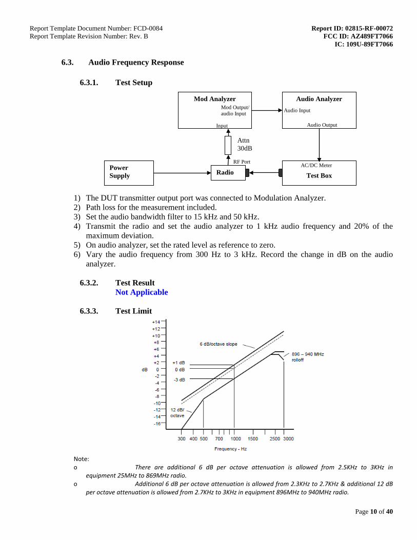
6.3.1. Test Setup
1) The DUT transmitter output port was connected to Modulation Analyzer. 2) Path loss for the measurement included. 3) Set the audio bandwidth filter to 15 kHz and 50 kHz. 4) Transmit the radio and set the audio analyzer to 1 kHz audio frequency and 20% of the
maximum deviation. 5) On audio analyzer, set the rated level as reference to zero. 6) Vary the audio frequency from 300 Hz to 3 kHz. Record the change in dB on the audio
analyzer.
6.3.2. Test Result Not Applicable
6.3.3. Test Limit
Note: o There are additional 6 dB per octave attenuation is allowed from 2.5KHz to 3KHz in
equipment 25MHz to 869MHz radio. o Additional 6 dB per octave attenuation is allowed from 2.3KHz to 2.7KHz & additional 12 dB
per octave attenuation is allowed from 2.7KHz to 3KHz in equipment 896MHz to 940MHz radio.
Power Supply
Mod Analyzer
Input
Audio Analyzer
Audio Output
Test Box
AC/DC Meter Radio
RF Port
Mod Output/ audio Input Audio Input
Attn 30dB
Report Template Document Number: FCD-0084 Report ID: 02815-RF-00072 Report Template Revision Number: Rev. B FCC ID: AZ489FT7066 IC: 109U-89FT7066
Page 11 of 40
6.4. Audio Low Pass Filter Response
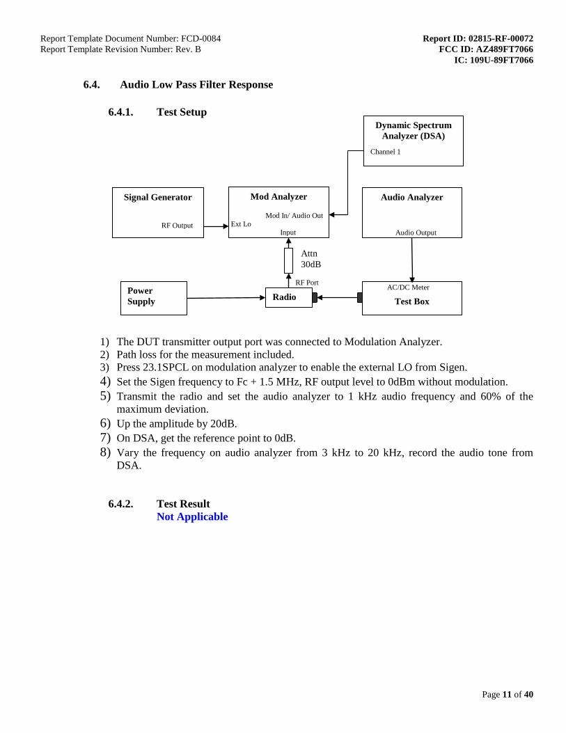
6.4.1. Test Setup
1) The DUT transmitter output port was connected to Modulation Analyzer. 2) Path loss for the measurement included. 3) Press 23.1SPCL on modulation analyzer to enable the external LO from Sigen. 4) Set the Sigen frequency to Fc + 1.5 MHz, RF output level to 0dBm without modulation. 5) Transmit the radio and set the audio analyzer to 1 kHz audio frequency and 60% of the
maximum deviation. 6) Up the amplitude by 20dB. 7) On DSA, get the reference point to 0dB. 8) Vary the frequency on audio analyzer from 3 kHz to 20 kHz, record the audio tone from
DSA.
6.4.2. Test Result Not Applicable
Signal Generator
Power Supply
Mod Analyzer
Input
Audio Analyzer
Audio Output
Test Box
AC/DC Meter Radio
RF Port
Ext Lo
RF Output
Attn 30dB
Dynamic Spectrum Analyzer (DSA)
Channel 1
Mod In/ Audio Out

Report Template Document Number: FCD-0084 Report ID: 02815-RF-00072 Report Template Revision Number: Rev. B FCC ID: AZ489FT7066 IC: 109U-89FT7066
Page 12 of 40
6.4.3. Test Limit

Report Template Document Number: FCD-0084 Report ID: 02815-RF-00072 Report Template Revision Number: Rev. B FCC ID: AZ489FT7066 IC: 109U-89FT7066
Page 13 of 40
6.5. Modulation Limiting
6.5.1. Test Setup
1) The DUT transmitter output port was connected to Modulation Analyzer. 2) Path loss for the measurement included. 3) Set the audio bandwidth filter to 15 kHz. 4) Transmit the radio and set the audio analyzer to 1 kHz audio frequency and 60% of the
maximum deviation. 5) Record the frequency deviation as 0dB input level at 1kHz audio frequency. 6) Repeat the step and record the frequency deviation from -20 dB to 20dB by 5 dB increments
and different audio freq 300 Hz, 2.5 kHz and 3 kHz.
6.5.2. Test Result
Not Applicable
6.5.3. Test Limit Modulation shall not exceed 100 percent if amplitude modulation is employed.
Attn 30dB
Power Supply
Mod Analyzer
Input 50Ω
Audio Analyzer
Audio Output
Test Box
AC/DC Meter Radio
RF Port
LO in
Report Template Document Number: FCD-0084 Report ID: 02815-RF-00072 Report Template Revision Number: Rev. B FCC ID: AZ489FT7066 IC: 109U-89FT7066
Page 14 of 40
6.6. Occupied Bandwidth
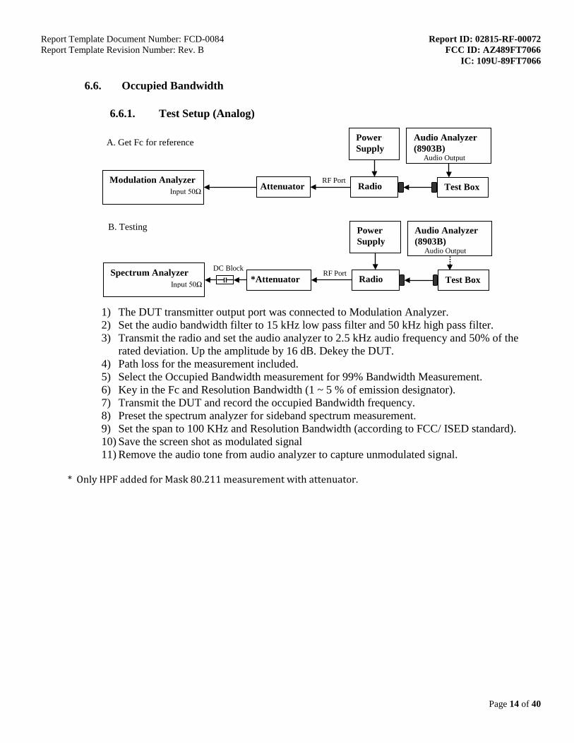
6.6.1. Test Setup (Analog)
1) The DUT transmitter output port was connected to Modulation Analyzer. 2) Set the audio bandwidth filter to 15 kHz low pass filter and 50 kHz high pass filter. 3) Transmit the radio and set the audio analyzer to 2.5 kHz audio frequency and 50% of the
rated deviation. Up the amplitude by 16 dB. Dekey the DUT. 4) Path loss for the measurement included. 5) Select the Occupied Bandwidth measurement for 99% Bandwidth Measurement. 6) Key in the Fc and Resolution Bandwidth (1 ~ 5 % of emission designator). 7) Transmit the DUT and record the occupied Bandwidth frequency. 8) Preset the spectrum analyzer for sideband spectrum measurement. 9) Set the span to 100 KHz and Resolution Bandwidth (according to FCC/ ISED standard). 10) Save the screen shot as modulated signal 11) Remove the audio tone from audio analyzer to capture unmodulated signal.
* Only HPF added for Mask 80.211 measurement with attenuator.
B. Testing
Modulation Analyzer Input 50Ω
A. Get Fc for reference
Radio
RF Port
Power Supply
Attenuator
Test Box
Audio Analyzer (8903B)
Audio Output
Spectrum Analyzer Input 50Ω
DC Block Radio
RF Port
Power Supply
*Attenuator
Test Box
Audio Analyzer (8903B)
Audio Output

Report Template Document Number: FCD-0084 Report ID: 02815-RF-00072 Report Template Revision Number: Rev. B FCC ID: AZ489FT7066 IC: 109U-89FT7066
Page 15 of 40
6.6.2. Test Result (Analog)

Report Template Document Number: FCD-0084 Report ID: 02815-RF-00072 Report Template Revision Number: Rev. B FCC ID: AZ489FT7066 IC: 109U-89FT7066
Page 16 of 40
6.6.3. Test Setup (Digital)
1) Program and set radio to operate in desire test frequency and digital mode with modulation. (4FSK, C4FM, CQPSK or other digital modulation form).
2) Path loss for the measurement included. 3) Select the Occupied Bandwidth measurement for 99% Bandwidth Measurement. 4) Key in the Fc and RBW (1 ~ 5 % of emission designator). 5) Transmit the DUT and record the occupied Bandwidth frequency. 6) Preset the spectrum analyzer for modulation emission spectrum measurement. 7) Set the span to 100 KHz and Resolution Bandwidth (according to FCC/ ISED standard). 8) Capture the screen shot as modulated signal.
AC/DC Meter
RF Port
Power Supply
Test Box
Radio
Attn 30dB
DC Block
Computer & Software Program Radio
PSA (Spectrum Analyzer)
Report Template Document Number: FCD-0084 Report ID: 02815-RF-00072 Report Template Revision Number: Rev. B FCC ID: AZ489FT7066 IC: 109U-89FT7066
Page 17 of 40
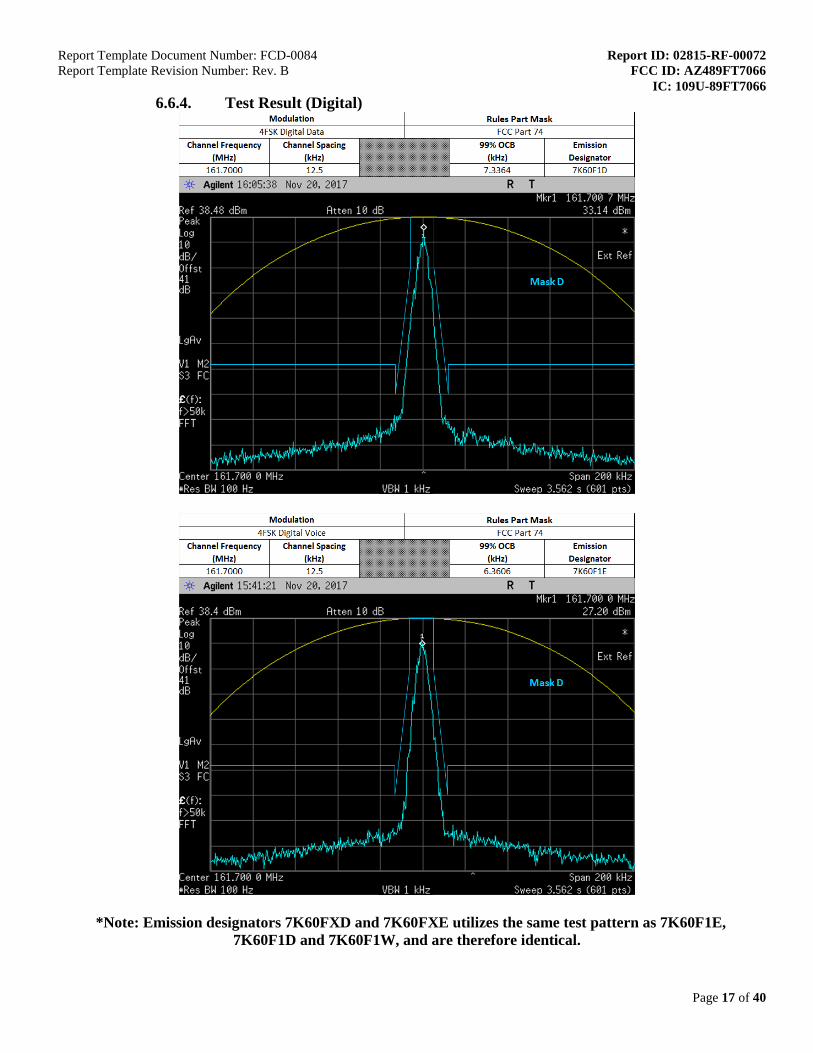
6.6.4. Test Result (Digital)
*Note: Emission designators 7K60FXD and 7K60FXE utilizes the same test pattern as 7K60F1E,
7K60F1D and 7K60F1W, and are therefore identical.

Report Template Document Number: FCD-0084 Report ID: 02815-RF-00072 Report Template Revision Number: Rev. B FCC ID: AZ489FT7066 IC: 109U-89FT7066
Page 18 of 40
6.6.5. Test Limit The 99% occupied bandwidth is the width of a frequency band such that, below the lower and above the upper frequency limits, the mean powers emitted are each equal to a specified percentage 0.5% of the total mean transmitted power.

Report Template Document Number: FCD-0084 Report ID: 02815-RF-00072 Report Template Revision Number: Rev. B FCC ID: AZ489FT7066 IC: 109U-89FT7066
Page 19 of 40
6.7. Band Edge Conducted Spurious Emission (Part 22)
6.7.1. Test Setup (Analog)
1) The DUT transmitter output port was connected to Modulation Analyzer. 2) Set the audio bandwidth filter to 15 kHz low pass filter and 50 kHz high pass filter. 3) Path loss for the measurement included. 4) Select the Occupied Bandwidth measurement for 99% and 26dB Emissions Bandwidth
Measurement. 5) Key in the Fc and RBW= 100Hz. 6) Transmit the DUT and record the occupied Bandwidth frequencies. 7) Preset the spectrum analyzer for band edge measurement. 8) The band edges of lowest and highest channels were measured. 9) The center frequency of spectrum is the band edge frequency, span is 60 kHz and RBW is
at least 1% of Emission Bandwidth. 10) Save the screen shot as modulated signal. 11) Remove the audio tone from audio analyzer to capture unmodulated signal.
B. Testing
Modulation Analyzer Input 50Ω
A. Get Fc for reference
Radio
RF Port
Power Supply
Attenuator Test Box
Audio Analyzer (8903B)
Audio Output
Spectrum Analyzer Input 50Ω
DC Block Radio
RF Port
Power Supply
Attenuator
Test Box
Audio Analyzer (8903B)
Audio Output

Report Template Document Number: FCD-0084 Report ID: 02815-RF-00072 Report Template Revision Number: Rev. B FCC ID: AZ489FT7066 IC: 109U-89FT7066
Page 20 of 40
6.7.2. Test Result (Analog)
Max Power

Report Template Document Number: FCD-0084 Report ID: 02815-RF-00072 Report Template Revision Number: Rev. B FCC ID: AZ489FT7066 IC: 109U-89FT7066
Page 21 of 40
Low Power

Report Template Document Number: FCD-0084 Report ID: 02815-RF-00072 Report Template Revision Number: Rev. B FCC ID: AZ489FT7066 IC: 109U-89FT7066
Page 22 of 40
6.7.3. Test Setup (Digital)
1) Program and set radio to operate in desire test frequency and digital mode with modulation. (4FSK**, C4FM or other digital modulation form).
2) Path loss for the measurement included. 3) Select the Occupied Bandwidth measurement for 99% and 26dB Emissions Bandwidth
Measurement. 4) Key in the Fc and RBW= 100Hz. 5) Transmit radio record the occupied Bandwidth frequencies. 6) Preset the spectrum analyzer for band edge measurement. 7) The band edges of lowest and highest channels were measured. 8) The center frequency of spectrum is the band edge frequency, span is 60 kHz and RBW is at
least 1% of Emission Bandwidth. 9) Save the screen shot.
*Note: Test patterns for all digital emissions (7K60F1E, 7K60F1D, 7K60F1W, 7K60FXE, 7K60FXW) are identical, hence only 7K60F1D is shown.
AC/DC Meter
RF Port
Power Supply
Test Box
Radio
Attn 30dB
DC Block
Computer & Software Program Radio
PSA (Spectrum Analyzer)

Report Template Document Number: FCD-0084 Report ID: 02815-RF-00072 Report Template Revision Number: Rev. B FCC ID: AZ489FT7066 IC: 109U-89FT7066
Page 23 of 40
6.7.4. Test Result (Digital) Max Power
Low Power
6.7.5. Test Limit The power of any emission outside of the authorized operating frequency ranges must be attenuated below the transmitting power (P) by a factor of at least 43 + 10 log(P) dB.

Report Template Document Number: FCD-0084 Report ID: 02815-RF-00072 Report Template Revision Number: Rev. B FCC ID: AZ489FT7066 IC: 109U-89FT7066
Page 24 of 40
6.8. Transient Frequency Behavior
6.8.1. Test Setup
1) Connect the setup as figure above. 2) Path loss for the measurement included. 3) Set on Sigen with the assigned center frequency, internal 1 kHz FM tone.
FM Deviation: Analog 25kHz Channel Spacing = 25 kHz Analog 12.5 kHz Channel Spacing = 12.5 kHz C4FM = 12.5 kHz
4) Turn on 50 kHz high pass filter and 15 kHz low pass filter on modulation analyzer. 5) Supply sufficient attenuation ATT to provide the output power of ≤ -11dBm into power
meter when UUT is keying up. 6) Note the power level on power meter and dekey the UUT. 7) Adjust the amplitude of the signal generator to the level power meter, maintained the
amplitude throughout the rest of the measurement. 8) Connect the output to modulation analyzer. 9) Set the horizontal sweep rate on the storage oscilloscope to 10 milliseconds per division and
adjust the display to continuously view the 1000 Hz. Adjust the vertical amplitude control of the oscilloscope to display the 1000 Hz at 4 divisions vertically centered on the display.
10) Reduce 30dB attenuation and transmit the radio to get the trigger line. 11) Capture the screen shot for key-up (rising edge) and de-key (falling edge) mode.
6.8.2. Test Result Not Applicable
50Ω Termination
Test Box
UUT ATT
Bidirectional Coupler
Incident (20dB) Reflected (20dB)
3 way pad
Power meter
Mod analyzer
Mod Out RF IN
Oscilloscope
CH 1 CH 2
SIGEN RF out
RF Detector

Report Template Document Number: FCD-0084 Report ID: 02815-RF-00072 Report Template Revision Number: Rev. B FCC ID: AZ489FT7066 IC: 109U-89FT7066
Page 25 of 40
6.8.3. Test Limit Transmitters designed to operate in the 150-174 MHz and 421-512 MHz frequency bands must maintain transient frequencies within the maximum frequency difference limits during the time intervals indicated:
Time intervals1 2 Maximum frequency difference3
All equipment
150 to 174 MHz 421 to 512 MHz
Transient Frequency Behavior for Equipment Designed to Operate on 25 kHz Channels t1
4 ±25.0 kHz 5.0 ms 10.0 ms t2 ±12.5 kHz 20.0 ms 25.0 ms t3
4 ±25.0 kHz 5.0 ms 10.0 ms Transient Frequency Behavior for Equipment Designed to Operate on 12.5 kHz Channels t1
4 ±12.5 kHz 5.0 ms 10.0 ms t2 ±6.25 kHz 20.0 ms 25.0 ms t3
4 ±12.5 kHz 5.0 ms 10.0 ms Transient Frequency Behavior for Equipment Designed to Operate on 6.25 kHz Channels t1
4 ±6.25 kHz 5.0 ms 10.0 ms t2 ±3.125 kHz 20.0 ms 25.0 ms t3
4 ±6.25 kHz 5.0 ms 10.0 ms
1on is the instant when a 1 kHz test signal is completely suppressed, including any
capture time due to phasing. t1 is the time period immediately following ton. t2 is the time period immediately following t1. t3 is the time period from the instant when the transmitter is turned off until toff. toff is the instant when the 1 kHz test signal starts to rise. 2 During the time from the end of t2 to the beginning of t3, the frequency difference
must not exceed the limits specified in §90.213. 3 Difference between the actual transmitter frequency and the assigned transmitter
frequency. 4 If the transmitter carrier output power rating is 6 watts or less, the frequency
difference during this time period may exceed the maximum frequency difference for this time period.

Report Template Document Number: FCD-0084 Report ID: 02815-RF-00072 Report Template Revision Number: Rev. B FCC ID: AZ489FT7066 IC: 109U-89FT7066
Page 26 of 40
6.9. Adjacent Channel Power
6.9.1. Test Setup (Analog)
1) The DUT transmitter output port was connected to modulation analyzer. 2) Path loss for the measurement included. 3) Transmit the radio and turn on 1st audio analyzer with audio frequency 650Hz, 50% rated
deviation, and record the amplitude value as AmpT1. 4) Turn off Audio analyzer 1 and turn on audio analyzer 2, set the audio frequency to 2.2 kHz
and 50% deviation. Record the amplitude as AmpT2. 5) Turn both audio analyzers ON and up 10dB amplitude level. 6) Connect the output to PSA and set to assigned center frequency. 7) Set Span, RBW and VBW as shown in FCC rules part 90.543. 8) Transmit the radio and record the ACP value in dBc.
6.9.2. Test Result Not Applicable
Power Supply
PSA (Spectrum Analyzer)
Input
Audio Analyzer 1 & 2
Audio Out
Test Box
AC/DC Meter Radio
RF Port
Attn 30dB
DC Block
T-Joint Combiner
Mod Analyzer
RF input

Report Template Document Number: FCD-0084 Report ID: 02815-RF-00072 Report Template Revision Number: Rev. B FCC ID: AZ489FT7066 IC: 109U-89FT7066
Page 27 of 40
6.9.3. Test Setup (Digital)
1) Program and set radio to operate in desire test frequency and digital mode with modulation. (4FSK, C4FM, CQPSK or other digital modulation form).
2) Path loss for the measurement included. 3) Prepare setup as per picture. 4) Turn on the ACP Measurement – Press Measure, ACP. 5) Set Span, RBW and VBW as shown in FCC rules part 90.543. 6) Transmit the radio and record the ACP value in dBc.
6.9.4. Test Result Not Applicable
RF Port
Power Supply
Test Box
Radio
Attn 30dB
DC Block
Computer & Software Program Radio
PSA (Spectrum Analyzer)

Report Template Document Number: FCD-0084 Report ID: 02815-RF-00072 Report Template Revision Number: Rev. B FCC ID: AZ489FT7066 IC: 109U-89FT7066
Page 28 of 40
6.9.5. Test Limit

Report Template Document Number: FCD-0084 Report ID: 02815-RF-00072 Report Template Revision Number: Rev. B FCC ID: AZ489FT7066 IC: 109U-89FT7066
Page 29 of 40

Report Template Document Number: FCD-0084 Report ID: 02815-RF-00072 Report Template Revision Number: Rev. B FCC ID: AZ489FT7066 IC: 109U-89FT7066
Page 30 of 40
6.10. Conducted Spurious Emission
6.10.1. Test Setup
1) The DUT transmitter output port was connected to Spectrum Analyzer with above setup. 2) Program and set radio to operate in desire test frequency and mode. (Analog / digital modulation
form). 3) Adjust the PSA RBW = 100kHz for spur emission below 1GHz, and 1MHz for spur emission above
1GHz. 4) Set the Ref offset from the pathloss offset calibration file. 5) Adjust the center frequency of the spectrum analyzer for incremental coverage of the range from:
(a) The lowest radio frequency to Fc – Test BW (b) Fc + Test BW to Freq < 2Fc.
6) Record the levels of spurious emissions and dekey the UUT. 7) Turn On HPF path and Key up the UUT. 8) Adjust the PSA Freq for incremental coverage of range from 2Fc to 10Fc. 9) The levels recorded are the absolute levels of conducted spurious emissions in dBm.
Spectrum Analyzer Input 50Ω Radio
RF Port DC Block
30dB pad
HPF
Power Supply
Test Box AC/DC meter

Report Template Document Number: FCD-0084 Report ID: 02815-RF-00072 Report Template Revision Number: Rev. B FCC ID: AZ489FT7066 IC: 109U-89FT7066
Page 31 of 40
6.10.2. Test Result (Analog)
Analog: 161.7 MHz, 20kHz kHz Channel Spacing, Max Power
Frequency Range Highest Spur Freq (MHz)
Spurious Level (dBm)
Failing Limit (dBm) Remark
9kHz ~ (Fc-Test BW) 78.81 -37.19 -13 Pass (Fc-Test BW)~2Fc 317.46 -39.20 -13 Pass
2Fc~1GHz 485.10 323.40
-53.29 -58.35 -13 Pass
1GHz~10Fc 1276.5 -49.44 -13 Pass

Report Template Document Number: FCD-0084 Report ID: 02815-RF-00072 Report Template Revision Number: Rev. B FCC ID: AZ489FT7066 IC: 109U-89FT7066
Page 32 of 40
Analog: 161.7 MHz, 20kHz kHz Channel Spacing, Low Power
Frequency Range Highest Spur Freq (MHz)
Spurious Level (dBm)
Failing Limit (dBm) Remark
9kHz ~ (Fc-Test BW) 74.61 -37.56 -13 Pass (Fc-Test BW)~2Fc 295.4 -40.67 -13 Pass
2Fc~1GHz 485.1 -53.62 -13 Pass 1GHz~10Fc 1241.7 -49.29 -13 Pass

Report Template Document Number: FCD-0084 Report ID: 02815-RF-00072 Report Template Revision Number: Rev. B FCC ID: AZ489FT7066 IC: 109U-89FT7066
Page 33 of 40
6.10.1. Test Result (Digital)
Not Applicable
6.10.2. Test Limit
Table below summarized the power of any emission outside a licensee’s frequency block shall be attenuated below the transmitter power (P) by at least
Channel Spacing
Part 22 Part 24D Part 74 Part 80 Part 90
12.5kHz 43 + log10(P)
(-13 dBm)
43 + log10(P) (-13 dBm) 43 + log10(P)
(-13 dBm)
Not Applicable 50 + log10(P)
(-20 dBm)
25kHz Not Applicable 43 + log10(P)
(-13 dBm) Not Applicable

Report Template Document Number: FCD-0084 Report ID: 02815-RF-00072 Report Template Revision Number: Rev. B FCC ID: AZ489FT7066 IC: 109U-89FT7066
Page 34 of 40
6.11. Radiated Spurious Emission
6.11.1. Test Setup
1) The spectrum setting for scanning Radiated Emission below 1 GHz is RBW = 100 kHz,
VBW = 300 kHz and above 1 GHz is RBW = 1 MHz, VBW = 3 MHz. Detector mode is positive peak.
2) In the semi-anechoic chamber, setup as illustrated above the EUT placed on the 0.8m height of Turn Table, rotated the table around 360 degrees to search the maximum radiation power and receiver antenna shall be rotated vertical and horizontal polarization and moved height from 1m to 4m to find the maximum polar radiated power. The “Read Value” is the spectrum reading the maximum power value.
3) The substitution antenna is substituted for EUT at the same position and signals generator (S.G) export the CW signal to the substitution antenna via a TX cable. The receiver antenna shall be rotated vertical and horizontal polarization and moved height from 1m to 4m to find the maximum radiation power. Record the power level of maximum radiation power from spectrum. So, the measured substitution value = Ref level of S.G + TX cables loss – Substituted Antenna Gain.
4) Final Radiated Spurious Emission = “Read Value” + Measured substitution value.

Report Template Document Number: FCD-0084 Report ID: 02815-RF-00072 Report Template Revision Number: Rev. B FCC ID: AZ489FT7066 IC: 109U-89FT7066
Page 35 of 40
6.11.2. Test Result (Analog)
SAC Transmitter Radiated Emission:
Model Number: MDH56JDN9RA1AN S/N: 871TRTT139 SR:02815-RF-00072 Battery Part No: NNTN8129A Accy Part No: NA
Test Mode: TX Analog 161.700000 MHz 20 kHz 1.000 Watt(s) /Low Power
Frequency
(MHz) Limit Horizontal Measured Emission Equiv Pwr Into Ideal Dipole (dBm)
Vertical Measured Emission Equiv Pwr Into ideal Dipole (dBm)
323.4000 -13.0000 -91.5331 ** -91.1389 **
485.1000 -13.0000 -86.4435 ** -88.0461 **
646.8000 -13.0000 -86.2205 ** -85.6304 **
808.5000 -13.0000 -85.5727 ** -83.9745 **
970.2000 -13.0000 -83.8948 ** -82.2182 **
1131.9000 -13.0000 -61.9323 ** -61.5086 **
1293.6000 -13.0000 -61.0008 ** -60.7920 **
1455.3000 -13.0000 -60.5658 ** -60.6110 **
1617.0000 -13.0000 -59.3166 ** -57.3103 **
RADIATED SPURIOUS EMISSIONS
-100
-90
-80
-70
-60
-50
-40
-30
-20
-10
0
323.4 485.1 646.8 808.5 970.2 1132 1294 1455 1617Frequency (MHz)
Emis
sion
Lev
el (d
Bm)
Horizontal MeasuredEmission Equiv Pwr IntoIdeal Dipole (dBm)Vertical MeasuredEmission Equiv Pwr IntoIdeal Dipole (dBm)Failing Limit
The data presented here was taken using the substitution method as found in the TIA/EIA-603D document. Motorola Penang EMC Lab - Test Performed by: Nazrin&Qawiman Thu, Jan 12, 2017 FCC Registration: 772092 Industry Canada: 109AK
Remarks: ** Indicates the spurious emission could not be detected due to noise limitations or ambient. *Pursuant to CFR 47 Part 2.1057 ( c ), emissions attenuated more than 20 dB below the permissible limit are not reported
System MU: 5.01 dB
Temp(Deg): 23.4 Hum(%RH): 71.5
Remarks: Passed Results Marginal Results Failed Results

Report Template Document Number: FCD-0084 Report ID: 02815-RF-00072 Report Template Revision Number: Rev. B FCC ID: AZ489FT7066 IC: 109U-89FT7066
Page 36 of 40
SAC Transmitter Radiated Emission: Model Number: MDH56JDN9RA1AN S/N: 871TRTT139 SR:02815-RF-00072
Battery Part No: NNTN8129A Accy Part No: NA Test Mode: TX Analog
161.700000 MHz 20 kHz 6.000 Watt(s) /Max Power
Frequency (MHz) Limit Horizontal Measured Emission Equiv
Pwr Into Ideal Dipole (dBm) Vertical Measured Emission Equiv Pwr
Into ideal Dipole (dBm)
323.4000 -13.0000 -91.6486 ** -90.1168 **
485.1000 -13.0000 -87.0043 ** -87.0520 **
646.8000 -13.0000 -85.9929 ** -86.3987 **
808.5000 -13.0000 -85.0128 ** -83.8642 **
970.2000 -13.0000 -84.5234 ** -83.0408 **
1131.9000 -13.0000 -62.0263 ** -60.6600 **
1293.6000 -13.0000 -60.4424 ** -61.6376 **
1455.3000 -13.0000 -60.8636 ** -60.6902 **
1617.0000 -13.0000 -60.1705 ** -60.6883 **
RADIATED SPURIOUS EMISSIONS
-100
-90
-80
-70
-60
-50
-40
-30
-20
-10
0
323.4 485.1 646.8 808.5 970.2 1132 1294 1455 1617Frequency (MHz)
Emis
sion
Lev
el (d
Bm)
Horizontal MeasuredEmission Equiv Pwr IntoIdeal Dipole (dBm)Vertical MeasuredEmission Equiv Pwr IntoIdeal Dipole (dBm)Failing Limit
The data presented here was taken using the substitution method as found in the TIA/EIA-603D document. Motorola Penang EMC Lab - Test Performed by: Nazrin&Qawiman Thu, Jan 12, 2017 FCC Registration: 772092 Industry Canada: 109AK
Remarks: ** Indicates the spurious emission could not be detected due to noise limitations or ambient. *Pursuant to CFR 47 Part 2.1057 ( c ), emissions attenuated more than 20 dB below the permissible limit are not reported
System MU: 5.01 dB
Temp(Deg): 23.4 Hum(%RH): 71.5
Remarks: Passed Results Marginal Results Failed Results

Report Template Document Number: FCD-0084 Report ID: 02815-RF-00072 Report Template Revision Number: Rev. B FCC ID: AZ489FT7066 IC: 109U-89FT7066
Page 37 of 40
6.11.3. Test Result (Digital)
Not Applicable
6.11.4. Test Limit
Table below summarized the power of any emission outside a licensee’s frequency block shall be attenuated below the transmitter power (P) by at least
Channel Spacing
Part 22 Part 24D Part 74 Part 80 Part 90
12.5kHz 43 + log10(P)
(-13 dBm)
43 + log10(P) (-13 dBm) 43 + log10(P)
(-13 dBm)
Not Applicable 50 + log10(P)
(-20 dBm)
25kHz Not Applicable 43 + log10(P)
(-13 dBm) Not Applicable

Report Template Document Number: FCD-0084 Report ID: 02815-RF-00072 Report Template Revision Number: Rev. B FCC ID: AZ489FT7066 IC: 109U-89FT7066
Page 38 of 40
6.12. Effective Radiated Power (ERP) / GNSS (EIRP for 1559 - 1610MHz)
6.12.1. Test Setup
1) The spectrum setting for Equivalent Isotropically Radiated Power (EIRP) is RBW = 100 kHz,
VBW = 300 kHz. Detector Mode is RMS. 2) In the semi-anechoic chamber, setup as illustrated above the EUT placed on the 0.8m height
of Turn Table, rotated the table 45 degree each interval to search the maximum radiation power and receiver antenna shall be rotated vertical and horizontal polarization and moved height from 1m to 4m to find the maximum polar radiated power for each degree interval. The “Read Value” is the spectrum reading of maximum power value.
3) The substitution antenna is substituted for EUT at the same position and signals generator (S.G) export the CW signal to the substitution antenna via a TX cable. The receiver antenna shall be rotated vertical and horizontal polarization and moved height from 1m to 4m to find the maximum radiation power. Record the power level of maximum radiation power from spectrum. So, the Measured substitution value = Ref level of S.G + TX cables loss – Substituted Antenna Gain.
4) EIRP = “Read Value” + Measured substitution value + 2.15. 6.12.2. Test Result
Not Applicable
6.12.3. Test Limit The maximum output power of the transmitter for mobile stations is 100 watts (20 dBW). Power is given in terms of effective radiated power (ERP). For operations in the 758-775 MHz and 788-805 MHz bands, all emissions including harmonics in the band 1559-1610 MHz shall be limited to −70 dBW/MHz equivalent isotropically radiated power (EIRP) for wideband signals, and −80 dBW EIRP for discrete emissions of less than 700 Hz bandwidth.
Report Template Document Number: FCD-0084 Report ID: 02815-RF-00072 Report Template Revision Number: Rev. B FCC ID: AZ489FT7066 IC: 109U-89FT7066
Page 39 of 40
6.13. AC Power Line Conducted Spur Emissions
6.13.1. Test Setup
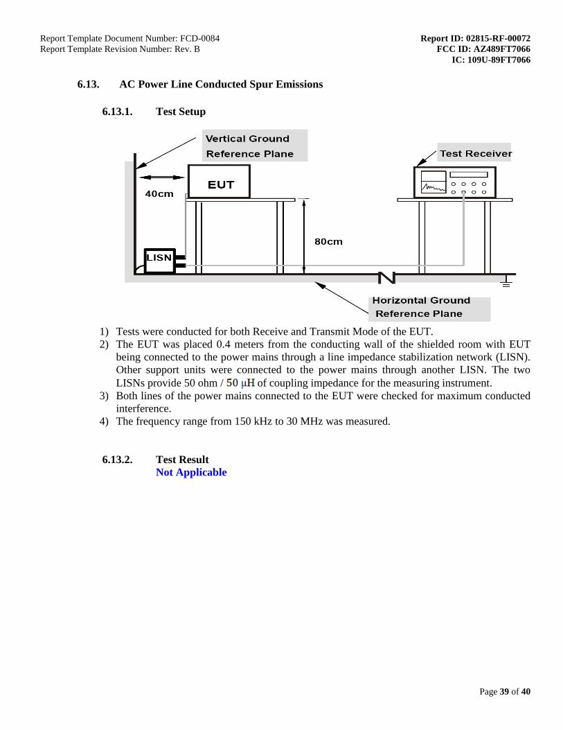
1) Tests were conducted for both Receive and Transmit Mode of the EUT. 2) The EUT was placed 0.4 meters from the conducting wall of the shielded room with EUT
being connected to the power mains through a line impedance stabilization network (LISN). Other support units were connected to the power mains through another LISN. The two LISNs provide 50 ohm / of coupling impedance for the measuring instrument.
3) Both lines of the power mains connected to the EUT were checked for maximum conducted interference.
4) The frequency range from 150 kHz to 30 MHz was measured.
6.13.2. Test Result Not Applicable

Report Template Document Number: FCD-0084 Report ID: 02815-RF-00072 Report Template Revision Number: Rev. B FCC ID: AZ489FT7066 IC: 109U-89FT7066
Page 40 of 40
6.13.3. Test Limit For AC Power Line Conducted Test Limit can be Class A or B depends on product classification.