test report iec 61010-1 safety requirements for electrical ... · therefore, all tests are...
TRANSCRIPT
www.tuv.com
Page 1 of 91 Report No. 17013552 001
TEST REPORT IEC 61010-1
Safety requirements for electrical equipment for me asurement, control, and laboratory use Part 1: General requirements
Report Reference No ...................... : 17013552 001
Tested by (name+signature) ............ : Zang Pengfei ......................................................
Witnessed by (name+signature) ...... : N/A ......................................................
Supervised by (name+signature)...... : N/A ......................................................
Approved by (name+signature) ........ : Mai Miao ......................................................
Date of issue..................................... : 2009-09-22
CB Testing Laboratory ................... : TUV Rheinland (Shenzhen) Co., Ltd.
Address ............................................ : 34 F Tower A, World Finance Centre, Shennan East Road 4003, Luohu District, Shenzhen 518001, P. R. China
Testing location/ procedure .............. : CBTL RMT SMT WMT TMP
Testing location/ address.................. : Unit B, 1F, 2nd Building, Shenzhen Cyber-Tech Zone, 7th High-Tech South Avenue, High-Tech Industrial Park, Shenzhen 518057, P. R. China
Applicant’s name ............................ : Dragon Laboratory Instruments Limited
Address ............................................ : F3, Block 12, Yu Hua Road 28, Area B, Konggang Industrial Development Zone, Shunyi District, Beijing 101318, P.R. China
Test specification:
Standard ........................................... : IEC/EN 61010-1: 2001 UL 61010-1:2004, CAN/ CSA C22.2 No. 61010-1-2004
Test procedure ................................. : CB
Non-standard test method…………..: N/A
Test Report Form No ...................... : IEC61010_D
TRF Originator.................................. : VDE (Modified by TÜV Rheinland Shenzhen Office)
Master TRF....................................... : Dated 2005-02-14 (North America deviation added)
Copyright © 2005 IEC System for Conformity Testing and Certification of Electrical Equipment (IECEE), Geneva, Switzerland. All rights reserved.
This publication may be reproduced in whole or in part for non-commercial purposes as long as the IECEE is acknowledged as copyright owner and source of the material. IECEE takes no responsibility for and will not assume liability for damages resulting from the reader's interpretation of the reproduced material due to its placement and context.
Test item description .....................: Vortex Mixer
Trade Mark ....................................... : DragonLAB
Manufacturer .................................... : Dragon Laboratory Instruments Limited
Model/Type reference....................... : MX-S, MX-F
Ratings ............................................. : For EU: 220-230VAC, 50Hz, 60W For NA: 110-120VAC, 60Hz, 60W

www.tuv.com
Page 2 of 91 Report No. 17013552 001
TRF No. IEC61010_D TRF originator: VDE
Copy of marking plate:
Label of MX-S for EU:
Label of MX-S for NA:
Label of MX-F for EU:
Label of MX-F for NA:

www.tuv.com
Page 3 of 91 Report No. 17013552 001
TRF No. IEC61010_D TRF originator: VDE
Summary of testing:
The instrument is designed for shaking liquid in tube, intended to be used in lab or schools. It uses the principle of cam vibration technique to make the liquid in a tube well-distributed.
2 types: MX-S and MX-F were considered in this report. The shaking speed of MX-S is adjustable from 0 to 2500 rpm, but type of MX-F has a fixed speed lower than 2500 rpm.
Therefore, all tests are performed on type MX-S according to IEC 61010-1:2001. North America national deviation according to CAN/ CSA C22.2 No. 61010-1-2004 and UL 61010-1:2004 have been evaluated. All tests and evaluations are performed according to the user’s final configurations in the instruction. The results can refer to related sub-clause in this report.
All test results are based on type MX-S if type not specified.
Test items see below table for detail.
4.4.2.2 Single fault – Protective conductor
4.4.2.4 Single fault – Motor
4.4.2.9 Single fault – Cooling
5.1.3.c Mains supply
5.3 Durability of markings
6. Values in normal condition (6.1.1 / 6.3.1)
6.3.1 / 2 Accessible Current (normal condition / single fault condition)
6.5.1.2 Tightening torque test
6.5.1.3/4 Bonding impedance of equipment
6.8 Dielectric strength tests + humidity
6.10.2 Cord anchorage
7.3 Stability tests
8.2 Drop test
10 Temperature measurements
10.5.3 Ball pressure test
11 Hazards from fluids (cleaning/spillage)
Annex D Working voltages & Creepage and Clearances
www.tuv.com
Page 4 of 91 Report No. 17013552 001
TRF No. IEC61010_D TRF originator: VDE
Test item particulars
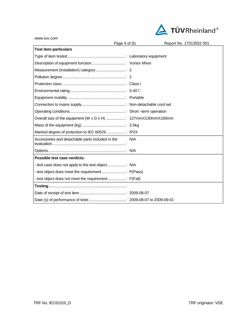
Type of item tested....................................................... : Laboratory equipment
Description of equipment function................................ : Vortex Mixer
Measurement (installation) category............................ : 2
Pollution degree............................................................ : 2
Protection class ............................................................ : Class I
Environmental rating..................................................... : 5-40
Equipment mobility ....................................................... : Portable
Connection to mains supply ......................................... : Non-detachable cord set
Operating conditions..................................................... : Short –term operation
Overall size of the equipment (W x D x H) .................. : 127mmX130mmX160mm
Mass of the equipment (kg).......................................... : 3.5kg
Marked degree of protection to IEC 60529.................. : IP2X
Accessories and detachable parts included in the evaluation...................................................................... :
N/A
Options.......................................................................... : N/A
Possible test case verdicts:
- test case does not apply to the test object..................: N/A
- test object does meet the requirement .......................: P(Pass)
- test object does not meet the requirement .................: F(Fail)
Testing ..........................................................................:
Date of receipt of test item ............................................: 2009-08-07
Date (s) of performance of tests ...................................: 2009-08-07 to 2009-09-01
www.tuv.com
Page 5 of 91 Report No. 17013552 001
TRF No. IEC61010_D TRF originator: VDE
General remarks:
This report is not valid as a CB Test Report unless signed by an approved CB Testing Laboratory and appended to a CB Test Certificate issued by an NCB in accordance with IECEE 02.
The test results presented in this report relate only to the object tested. This report shall not be reproduced, except in full, without the written approval of the Issuing testing laboratory.
"(see Form A.#)" refers to a table included or appended to the report "(see Enclosure #)" refers to additional information appended to the report.
Comments: Summary of compliance with National Differences (for explanation of codes see below): EU Group Differences, EU Special National Conditions, EU A-Deviations, AT, BE, CA, CH, CZ, DE, DK, FI, FR, GR, HU, IL, IT, NL, NO, PL, SE, SI, SK, US. AT=Austria, BE=Belgium, CA=Canada, CH=Switzerland, CZ=Czech Republic, DE=Germany, DK=Denmark, FI=Finland, FR=France, GR=Greece, HU=Hungary, IL=Israel, IT=Italy, NL=The Netherlands, NO=Norway, PL=Poland, SE=Sweden, SI=Slovenia, SK=Slovakia, US=United States of America. This 90 pages test reports have another 10 pages photo documents.
For National Differences see end of this test report.
Factory:
Dragon Laboratory Instruments Limited F3, Block 12, Yu Hua Road 28, Area B, Konggang Industrial Development Zone, Shunyi District, Beijing 101318, P.R. China
Throughout this report a point is used as the decimal separator. List of test equipment included in this report.
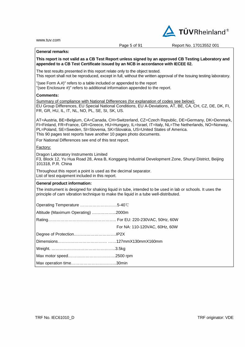
General product information:
The instrument is designed for shaking liquid in tube, intended to be used in lab or schools. It uses the principle of cam vibration technique to make the liquid in a tube well-distributed. Operating Temperature ………………………5-40
Altitude (Maximum Operating) ……………...2000m
Rating………………………………………….. For EU: 220-230VAC, 50Hz, 60W
For NA: 110-120VAC, 60Hz, 60W
Degree of Protection………………………….IP2X
Dimensions……………………………… ……127mmX130mmX160mm
Weight. ………………………………………..3.5kg
Max motor speed……….…………………….2500 rpm
Max operation time……………………………30min

www.tuv.com
Page 6 of 91 Report No. 17013552 001
TRF No. IEC61010_D TRF originator: VDE
TABLE: 1 - Test Report Index Page P
Document No.
Documents included / attached to this report (description) Page Numbers
TABLE 1 This page 1
TABLE 2 List of test equipment used for measurements 1
TABLE 3 List of safety relevant components 2
www.tuv.com
Page 7 of 91 Report No. 17013552 001
TRF No. IEC61010_D TRF originator: VDE
TABLE: 2 - Test equipment list N/A
Item Type Equipment No. Calibration date
Comments
Last1 Due
1) or interval between calibrations.
Remark: Please refer to the separate page.

www.tuv.com
Page 8 of 91 Report No. 17013552 001
IEC 61010-1
Clause Requirement + Test Result - Remark Verdict
TRF No. IEC61010_D TRF originator: VDE
TABLE: 3 - List of components and circuits relied o n for safety P
Unique component reference or location
Application/function Manufacturer trademark
(NOTE 1)
Type / model Technical data (NOTE 2)
Mark(s) of conformity evidence of acceptance
(NOTE 3 and 4)
Plug (For EU) 3VTJ2 AC250V, 10A VDE 40012265
Plug (For NA)
Connection Zhenjiang Huayin Instrument and
Electrical Equipment Co., Ltd.
3UTJ2 AC125V, 10A UL E199813
Power cord (For EU) H03W-F AC300V, 3G0.75 mm² VDE 116312
Power cord (For NA)
Connection Zhenjiang Huayin Instrument and
Electrical Equipment Co., Ltd.
2UTJ3 AC125V, 3GAWG14 UL E199813
X Capacitor (C1)
Connection AID Electronics Corporation
MEX X2, 0.22uF, 275VAC UL E183539 VDE 094710
Y Capacitor (C2, C3)
Connection TDK Corporation CD Y1, 2.2nF, 250VAC UL E37861 VDE 138526
Fuse (F1, F2)
Protection COOPER BUSSMANN INC
SR-5-2A T2A, 250V VDE 122052 UL E14853
Power Switch Protection Pronic Electronics (Shenzhen) Co., Ltd.
BR-13E-11L 250V/125VAC, 5A/10A UL E105856 VDE 40027238
Action Switch Protection OMRON Corporation SS-5GL 250V3A UL E41515 VDE 129246
TUV J9451450
www.tuv.com
Page 9 of 91 Report No. 17013552 001
IEC 61010-1
Clause Requirement + Test Result - Remark Verdict
TRF No. IEC61010_D TRF originator: VDE
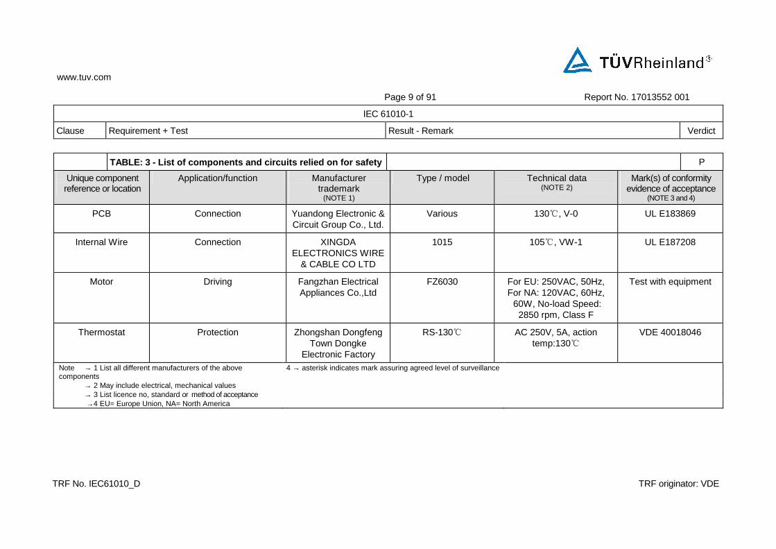
TABLE: 3 - List of components and circuits relied o n for safety P
Unique component reference or location
Application/function Manufacturer trademark
(NOTE 1)
Type / model Technical data (NOTE 2)
Mark(s) of conformity evidence of acceptance
(NOTE 3 and 4)
PCB Connection Yuandong Electronic & Circuit Group Co., Ltd.
Various 130, V-0 UL E183869
Internal Wire Connection XINGDA ELECTRONICS WIRE
& CABLE CO LTD
1015 105, VW-1 UL E187208
Motor Driving Fangzhan Electrical Appliances Co.,Ltd
FZ6030 For EU: 250VAC, 50Hz, For NA: 120VAC, 60Hz, 60W, No-load Speed:
2850 rpm, Class F
Test with equipment
Thermostat Protection Zhongshan Dongfeng Town Dongke
Electronic Factory
RS-130 AC 250V, 5A, action temp:130
VDE 40018046
Note → 1 List all different manufacturers of the above components
4 → asterisk indicates mark assuring agreed level of surveillance
→ 2 May include electrical, mechanical values → 3 List licence no, standard or method of acceptance →4 EU= Europe Union, NA= North America
www.tuv.com
Page 10 of 91 Report No. 17013552 001
IEC 61010-1
Clause Requirement + Test Result - Remark Verdict
TRF No. IEC61010_D TRF originator: VDE
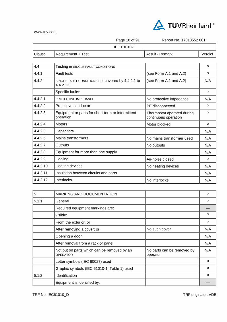
4.4 Testing in SINGLE FAULT CONDITIONS P
4.4.1 Fault tests (see Form A.1 and A.2) P
4.4.2 SINGLE FAULT CONDITIONS not covered by 4.4.2.1 to 4.4.2.12
(see Form A.1 and A.2) N/A
Specific faults: P
4.4.2.1 PROTECTIVE IMPEDANCE No protective impedance N/A
4.4.2.2 Protective conductor PE disconnected P
4.4.2.3 Equipment or parts for short-term or intermittent operation
Thermostat operated during continuous operation
P
4.4.2.4 Motors Motor blocked P
4.4.2.5 Capacitors N/A
4.4.2.6 Mains transformers No mains transformer used N/A
4.4.2.7 Outputs No outputs N/A
4.4.2.8 Equipment for more than one supply N/A
4.4.2.9 Cooling Air-holes closed P
4.4.2.10 Heating devices No heating devices N/A
4.4.2.11 Insulation between circuits and parts N/A
4.4.2.12 Interlocks No interlocks N/A
5 MARKING AND DOCUMENTATION P
5.1.1 General P
Required equipment markings are: —
visible: P
From the exterior; or P
After removing a cover; or No such cover N/A
Opening a door N/A
After removal from a rack or panel N/A
Not put on parts which can be removed by an OPERATOR
No parts can be removed by operator
N/A
Letter symbols (IEC 60027) used P
Graphic symbols (IEC 61010-1: Table 1) used P
5.1.2 Identification P
Equipment is identified by: —
www.tuv.com
Page 11 of 91 Report No. 17013552 001
IEC 61010-1
Clause Requirement + Test Result - Remark Verdict
TRF No. IEC61010_D TRF originator: VDE
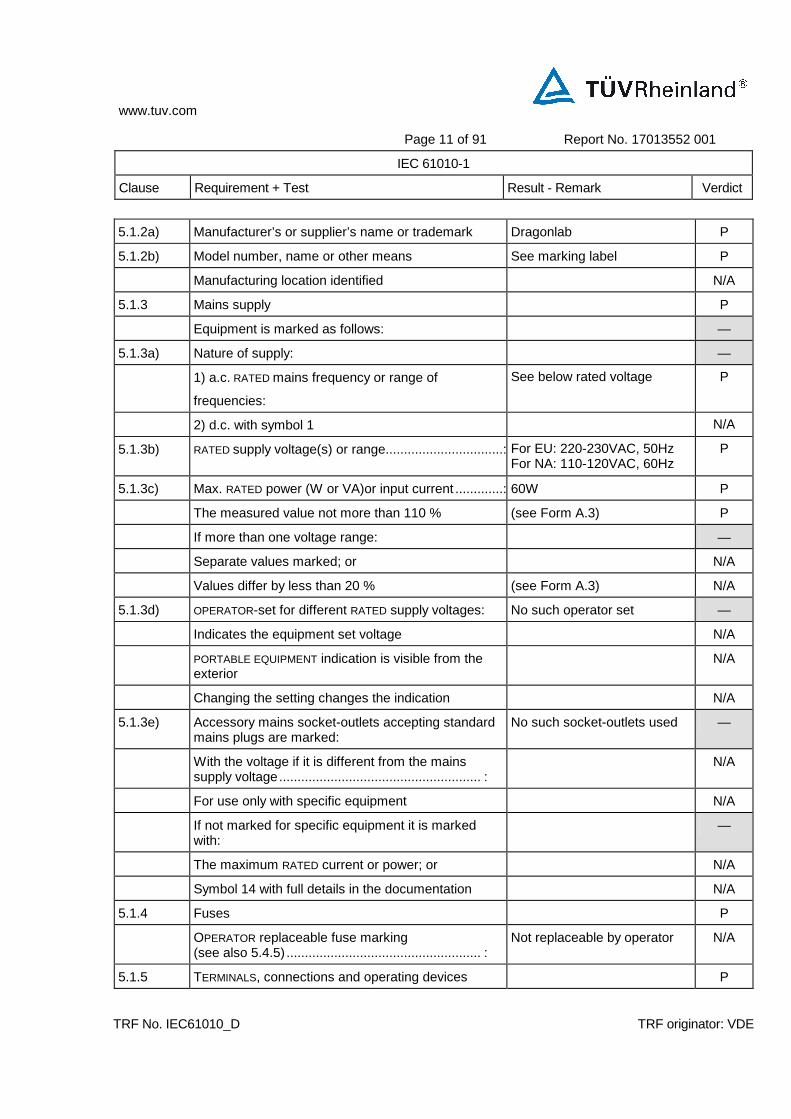
5.1.2a) Manufacturer’s or supplier’s name or trademark Dragonlab P
5.1.2b) Model number, name or other means See marking label P
Manufacturing location identified N/A
5.1.3 Mains supply P
Equipment is marked as follows: —
5.1.3a) Nature of supply: —
1) a.c. RATED mains frequency or range of
frequencies:
See below rated voltage P
2) d.c. with symbol 1 N/A
5.1.3b) RATED supply voltage(s) or range................................: For EU: 220-230VAC, 50Hz For NA: 110-120VAC, 60Hz
P
5.1.3c) Max. RATED power (W or VA)or input current .............: 60W P
The measured value not more than 110 % (see Form A.3) P
If more than one voltage range: —
Separate values marked; or N/A
Values differ by less than 20 % (see Form A.3) N/A
5.1.3d) OPERATOR-set for different RATED supply voltages: No such operator set —
Indicates the equipment set voltage N/A
PORTABLE EQUIPMENT indication is visible from the exterior
N/A
Changing the setting changes the indication N/A
5.1.3e) Accessory mains socket-outlets accepting standard mains plugs are marked:
No such socket-outlets used —
With the voltage if it is different from the mains supply voltage....................................................... :
N/A
For use only with specific equipment N/A
If not marked for specific equipment it is marked with:
—
The maximum RATED current or power; or N/A
Symbol 14 with full details in the documentation N/A
5.1.4 Fuses P
OPERATOR replaceable fuse marking (see also 5.4.5) ..................................................... :
Not replaceable by operator N/A
5.1.5 TERMINALS, connections and operating devices P

www.tuv.com
Page 12 of 91 Report No. 17013552 001
IEC 61010-1
Clause Requirement + Test Result - Remark Verdict
TRF No. IEC61010_D TRF originator: VDE
Where necessary for safety, indication of purpose of TERMINALS, connectors, controls and indicators marked
N/A
If insufficient space, symbol 14 used N/A
5.1.5.1 TERMINALS N/A
Mains supply TERMINALS identified N/A
Other TERMINAL marking ........................................ : N/A
5.1.5.1a) FUNCTIONAL EARTH TERMINALS (symbol 5 used) N/A
5.1.5.1b) PROTECTIVE CONDUCTOR TERMINALS: P
Symbol 6 is placed close to or on the TERMINAL; OR Symbol 6 marked P
Part of appliance inlet N/A
5.1.5.1c) TERMINALS of measuring and control circuits (symbol 7 used)
N/A
5.1.5.1d) HAZARDOUS LIVE TERMINALS supplied from the interior No such terminals N/A
Standard MAINS socket outlet; or N/A
RATINGS marked; or N/A
Symbol 14 used N/A
5.1.5.1e) ACCESSIBLE FUNCTIONAL EARTH TERMINALS: N/A
Self-evident; or N/A
Indication (symbol 8 acceptable) N/A
5.1.5.2 Measuring circuit TERMINALS N/A
Unless clear indication that below the limits of 50 V a.c. or 120 V d.c. to earth:
No measuring circuits N/A
Required markings are adjacent to TERMINALS; OR N/A
If insufficient space: —
On the RATING plate or scale plate; or N/A
TERMINAL is marked with symbol 14 N/A
5.1.5.2a) For CAT I measurement circuits: —
RATED voltage ....................................................... : N/A
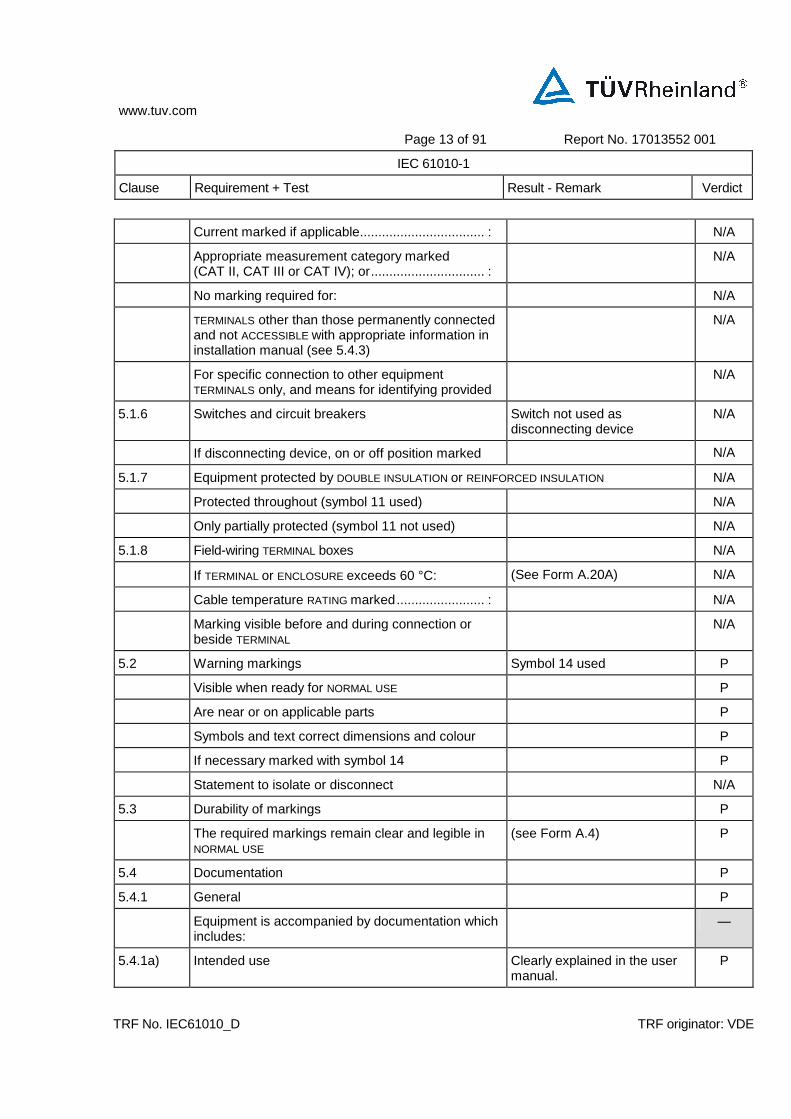
Current marked if applicable.................................. : N/A
Symbol 14 marked N/A
5.1.5.2b) For CAT II, CAT III or CAT IV measurement circuits: —
RATED voltage ....................................................... : N/A
www.tuv.com
Page 13 of 91 Report No. 17013552 001
IEC 61010-1
Clause Requirement + Test Result - Remark Verdict
TRF No. IEC61010_D TRF originator: VDE
Current marked if applicable.................................. : N/A
Appropriate measurement category marked (CAT II, CAT III or CAT IV); or............................... :
N/A
No marking required for: N/A
TERMINALS other than those permanently connected and not ACCESSIBLE with appropriate information in installation manual (see 5.4.3)
N/A
For specific connection to other equipment TERMINALS only, and means for identifying provided
N/A
5.1.6 Switches and circuit breakers Switch not used as disconnecting device
N/A
If disconnecting device, on or off position marked N/A
5.1.7 Equipment protected by DOUBLE INSULATION or REINFORCED INSULATION N/A
Protected throughout (symbol 11 used) N/A
Only partially protected (symbol 11 not used) N/A
5.1.8 Field-wiring TERMINAL boxes N/A
If TERMINAL or ENCLOSURE exceeds 60 °C: (See Form A.20A) N/A
Cable temperature RATING marked........................ : N/A
Marking visible before and during connection or beside TERMINAL
N/A
5.2 Warning markings Symbol 14 used P
Visible when ready for NORMAL USE P
Are near or on applicable parts P
Symbols and text correct dimensions and colour P
If necessary marked with symbol 14 P
Statement to isolate or disconnect N/A
5.3 Durability of markings P
The required markings remain clear and legible in NORMAL USE
(see Form A.4) P
5.4 Documentation P
5.4.1 General P
Equipment is accompanied by documentation which includes:
—
5.4.1a) Intended use Clearly explained in the user manual.
P

www.tuv.com
Page 14 of 91 Report No. 17013552 001
IEC 61010-1
Clause Requirement + Test Result - Remark Verdict
TRF No. IEC61010_D TRF originator: VDE
5.4.1b) Technical specification P
5.4.1c) Instructions for use P
5.4.1d) Name and address of manufacturer or supplier Provided in the user manual P
5.4.1e) Information specified in 5.4.2 to 5.4.5 P
5.4.1f) If marking of TERMINALS required, definition of measurement category
No measurement circuit N/A
5.4.1g) If CAT 1: N/A
Warning not to be used in CAT II, CAT III or CAT IV measurement circuits
N/A
RATINGS including RATED transient overvoltages ... : N/A
5.4.1 Warning statements and a clear explanation of warning symbols:
—
Provided in the documentation; or P
Information is marked on the equipment N/A
5.4.2 Equipment RATINGS P
Documentation includes: —
5.4.2a) Supply voltage or voltage range ............................ : For EU: 220-230VAC For NA: 110-120VAC
P
Frequency or frequency range............................... : For EU: 50Hz For NA: 60Hz
P
Power or current RATING ........................................ : 60W P
5.4.2b) Description of all input and output connections N/A
5.4.2c) RATING of insulation of external circuits, when such circuits are nowhere ACCESSIBLE
N/A
5.4.2d) Statement of the range of environmental conditions Stated in the user manual P
5.4.2e) Degree of protection (IEC 60529) IP2X P
5.4.3 Equipment installation P
Documentation includes instructions for: —
5.4.3a) Assembly, location and mounting requirements P
5.4.3b) Protective earthing P
5.4.3c) Connections to supply P
5.4.3d) PERMANENTLY CONNECTED EQUIPMENT: N/A
1) Supply wiring requirements N/A

www.tuv.com
Page 15 of 91 Report No. 17013552 001
IEC 61010-1
Clause Requirement + Test Result - Remark Verdict
TRF No. IEC61010_D TRF originator: VDE
2) If external switch or circuit-breaker, requirements and location recommendation
N/A
5.4.3e) Ventilation requirements N/A
5.4.3f) Special services (e. g. air, cooling liquid) N/A
5.4.3g) Maximum sound power level N/A
5.4.3h) Instructions about sound pressure N/A
5.4.3i) Permanently connected measuring TERMINALS: Not permanently connected equipment
N/A
Measurement category N/A
RATED maximum WORKING VOLTAGE or current N/A
5.4.4 Equipment operation P
Instructions for use include: Stated in the user manual —
5.4.4a) Identification of operating controls P
5.4.4b) Positioning for disconnection N/A
5.4.4c) Interconnection P
5.4.4d) Specification of intermittent operation limits 30min max. P
5.4.4e) Explanation of symbols used P
5.4.4f) Replacement of consumable materials No consumable materials N/A
5.4.4g) Cleaning and decontamination (see 11.2) Stated in the user manual P
5.4.4h) Listing of any poisonous or injurious gases and quantities
No such materials N/A
5.4.4i) Risk-reduction procedures relating to flammable liquids
No such liquids N/A
A statement about protection impairment if used in a manner not specified by the manufacturer
P
5.4.5 Equipment maintenance P
Instructions for RESPONSIBLE BODY include: Stated in the user manual —
Sufficient preventive maintenance and inspection information
P
Replacement of hoses or parts containing liquids, etc.
N/A
Specific battery type of user replaceable batteries No battery used N/A
Any manufacturer specified parts Clearly stated in the user manual.
P
RATING and characteristics of fuses Fuse not replaceable N/A

www.tuv.com
Page 16 of 91 Report No. 17013552 001
IEC 61010-1
Clause Requirement + Test Result - Remark Verdict
TRF No. IEC61010_D TRF originator: VDE
6 PROTECTION AGAINST ELECTRIC SHOCK (see Form A.5) P
6.1 General P
6.1.1 Requirements —
ACCESSIBLE parts not HAZADOUS LIVE in NORMAL CONDITION and SINGLE FAULT CONDITION
P
Conformity is checked by the determination of 6.2 and 6.3 followed by the tests of 6.4 to 6.11
P
6.1.2 Exceptions N/A
Capacitance test (see Forms A.6 and A.7) N/A
Parts not HAZARDOUS LIVE 10 s after interruption of supply
N/A
6.2 Determination of ACCESSIBLE parts P
6.2.1 General examination (see Form A.6) P
6.2.2 Openings above parts that are HAZARDOUS LIVE (see Form A.6) N/A
6.2.3 Openings for pre-set controls No such pre-set controls N/A
6.3 Permissible limits for ACCESSIBLE parts P
6.3.1 Values in NORMAL CONDITION (see Form A.7) P
6.3.2 Values in SINGLE FAULT CONDITION (see Form A.8) P
6.4 Protection in NORMAL CONDITION (see 6.2, 6.3.1, 6.7, 6.8 and 8.1)
P
6.4a) BASIC INSULATION (see annex D) P
6.4b) ENCLOSURES and BARRIERS Double insulation provided by plastic enclosure
P
6.4c) Impedance N/A
6.5 Protection in SINGLE FAULT CONDITION P
Additional protection is provided by: —
One or more of 6.5.1 to 6.5.3; or By protective bonding P
Automatic disconnection of the supply (6.5.4) No such device N/A
6.5.1 Protective BONDING P
ACCESSIBLE conductive parts: —
Separated by DOUBLE INSULATION or REINFORCED INSULATION; or
N/A
Bonded to the PROTECTIVE CONDUCTOR TERMINAL; or P
www.tuv.com
Page 17 of 91 Report No. 17013552 001
IEC 61010-1
Clause Requirement + Test Result - Remark Verdict
TRF No. IEC61010_D TRF originator: VDE
Separated by screen or BARRIER bonded to PROTECTIVE CONDUCTOR TERMINAL from parts which are HAZARDOUS LIVE
N/A
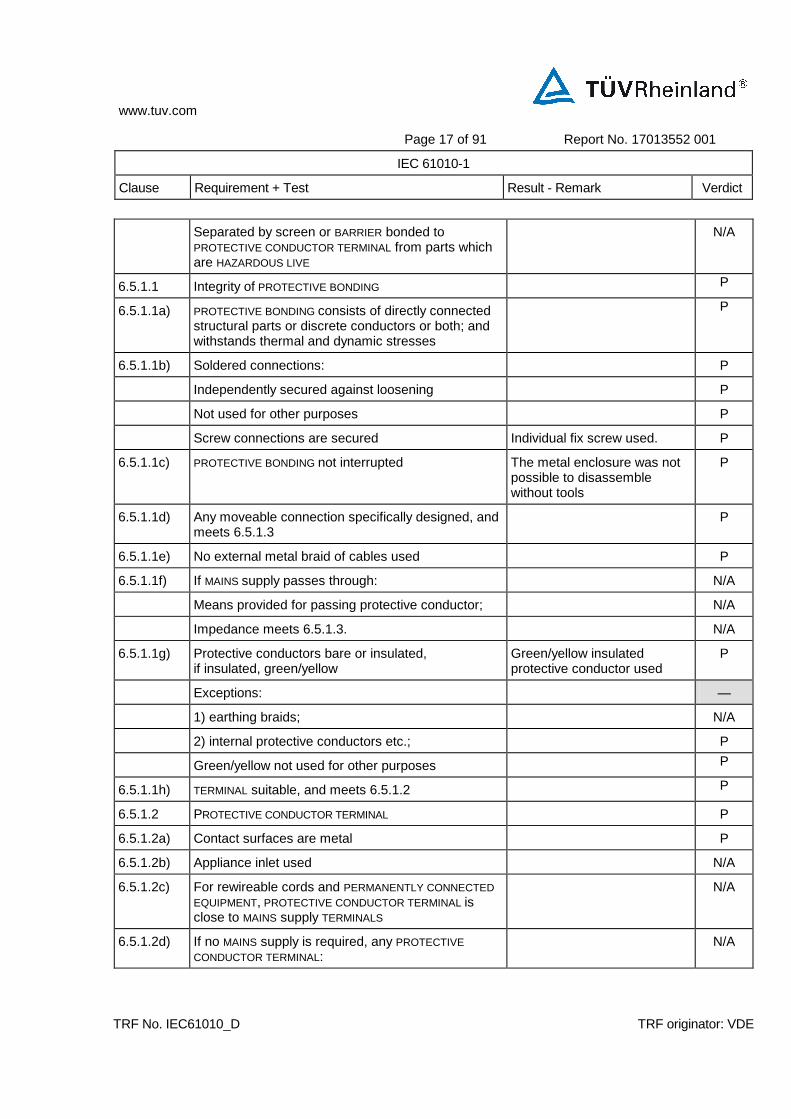
6.5.1.1 Integrity of PROTECTIVE BONDING P
6.5.1.1a) PROTECTIVE BONDING consists of directly connected structural parts or discrete conductors or both; and withstands thermal and dynamic stresses
P
6.5.1.1b) Soldered connections: P
Independently secured against loosening P
Not used for other purposes P
Screw connections are secured Individual fix screw used. P
6.5.1.1c) PROTECTIVE BONDING not interrupted The metal enclosure was not possible to disassemble without tools
P
6.5.1.1d) Any moveable connection specifically designed, and meets 6.5.1.3
P
6.5.1.1e) No external metal braid of cables used P
6.5.1.1f) If MAINS supply passes through: N/A
Means provided for passing protective conductor; N/A
Impedance meets 6.5.1.3. N/A
6.5.1.1g) Protective conductors bare or insulated, if insulated, green/yellow
Green/yellow insulated protective conductor used
P
Exceptions: —
1) earthing braids; N/A
2) internal protective conductors etc.; P
Green/yellow not used for other purposes P
6.5.1.1h) TERMINAL suitable, and meets 6.5.1.2 P
6.5.1.2 PROTECTIVE CONDUCTOR TERMINAL P
6.5.1.2a) Contact surfaces are metal P
6.5.1.2b) Appliance inlet used N/A
6.5.1.2c) For rewireable cords and PERMANENTLY CONNECTED EQUIPMENT, PROTECTIVE CONDUCTOR TERMINAL is close to MAINS supply TERMINALS
N/A
6.5.1.2d) If no MAINS supply is required, any PROTECTIVE CONDUCTOR TERMINAL:
N/A

www.tuv.com
Page 18 of 91 Report No. 17013552 001
IEC 61010-1
Clause Requirement + Test Result - Remark Verdict
TRF No. IEC61010_D TRF originator: VDE
Is near TERMINALS of circuit for which protective earthing is necessary
N/A
External if other TERMINALS external N/A
6.5.1.2e) Equivalent current-carrying capacity to MAINS supply TERMINALS
(see Form A.9) P
6.5.1.2f) If plug-in, makes first and breaks last N/A
6.5.1.2g) If also used for other bonding purposes, protective conductor:
No other purpose N/A
Applied first; N/A
Secured independently; N/A
Unlikely to be removed by servicing; or N/A
Warning marking requires replacement of protective conductor
N/A
6.5.1.2h) PROTECTIVE CONDUCTOR of measuring circuit: No need to provide protective conductor for measuring circuit.
N/A
1) Current RATING equivalent to measuring circuit TERMINAL;
N/A
2) PROTECTIVE BONDING: N/A
Not interrupted; or N/A
Indirect bonding used (see 6.5.1.5) N/A
6.5.1.2i) FUNCTIONAL EARTH TERMINALS allow independent connection
N/A
6.5.1.2j) If a binding screw used for PROTECTIVE CONDUCTOR TERMINAL:
Binding screw used P
Suitable size for bond wire P
Not smaller than M 4 (No. 6) M4 P
At least 3 turns of screw engaged More than 3 turns of screw engaged.
P
Contact pressure not capable of reduction by deformation of materials
P
Passes tightening torque test (see Form A.9) 3 times operation of assembly and disassembly tested
P
6.5.1.3 Impedance of PROTECTIVE BONDING of plug-connected equipment
(see Form A.10) P
www.tuv.com
Page 19 of 91 Report No. 17013552 001
IEC 61010-1
Clause Requirement + Test Result - Remark Verdict
TRF No. IEC61010_D TRF originator: VDE
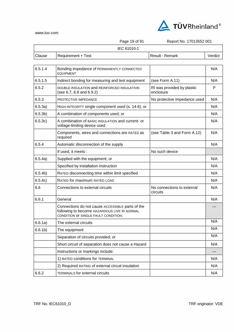
6.5.1.4 Bonding impedance of PERMANENTLY CONNECTED EQUIPMENT
N/A
6.5.1.5 Indirect bonding for measuring and test equipment (see Form A.11) N/A
6.5.2 DOUBLE INSULATION and REINFORCED INSULATION (see 6.7, 6.8 and 6.9.2)
RI was provided by plastic enclosure
P
6.5.3 PROTECTIVE IMPEDANCE No protective impedance used N/A
6.5.3a) HIGH-INTEGRITY single component used (s. 14.6); or N/A
6.5.3b) A combination of components used; or N/A
6.5.3c) A combination of BASIC INSULATION and current- or voltage-limiting device used
N/A
Components, wires and connections are RATED as required
(see Table 3 and Form A.12) N/A
6.5.4 Automatic disconnection of the supply N/A
If used, it meets : No such device
6.5.4a) Supplied with the equipment; or N/A
Specified by installation instruction N/A
6.5.4b) RATED disconnecting time within limit specified N/A
6.5.4c) RATED for maximum RATED LOAD N/A
6.6 Connections to external circuits No connections to external circuits
N/A
6.6.1 General N/A
Connections do not cause ACCESSIBLE parts of the following to become HAZARDOUS LIVE in NORMAL CONDITION or SINGLE FAULT CONDITION:
—
6.6.1a) The external circuits N/A
6.6.1b) The equipment N/A
Separation of circuits provided; or N/A
Short circuit of separation does not cause a Hazard N/A
Instructions or markings include: —
1) RATED conditions for TERMINAL N/A
2) Required RATING of external circuit insulation N/A
6.6.2 TERMINALS for external circuits N/A

www.tuv.com
Page 20 of 91 Report No. 17013552 001
IEC 61010-1
Clause Requirement + Test Result - Remark Verdict
TRF No. IEC61010_D TRF originator: VDE
TERMINALS which receive a charge from an internal capacito are not HAZARDOUS LIVE
(see Form A.7) N/A
High voltage TERMINALS energized from the interior are:
—
Not ACCESSIBLE if connected; or N/A
When unmated HAZARDOUS LIVE TERMINALS not ACCESSIBLE ; or
N/A
marked with symbol 12 N/A
6.6.3 Circuits with TERMINALS which are HAZARDOUS LIVE N/A
These circuits are: No hazardous live terminals —
Not connected to ACCESSIBLE conductive parts; or N/A
Connected to ACCESSIBLE conductive parts, but are not MAINS CIRCUITS and have one TERMINAL contact at earth potential
N/A
No ACCESSIBLE conductive parts are HAZARDOUS LIVE N/A
6.6.4 ACCESSIBLE TERMINALS for stranded conductors N/A
6.6.4a) No risk of accidental contact because: N/A
Located or shielded N/A
Self-evident or marked whether or not connected to ACCESSIBLE conductive parts
N/A
6.6.4b) ACCESSIBLE TERMINALS will not work loose N/A
6.7 CLEARANCES and CREEPAGE DISTANCES (See Form A.5 and A.13)
P
6.7.2.1 CTI requirements (See Form A.5) N/A
CTI tests performed N/A
6.8 Procedure for dielectric strength tests (See Form A.5 and A.14) P
6.9 Constructional requirements for protection against electric shock P
6.9.1 General P
If a failure could cause a HAZARD: —
6.9.1a) Security of wiring connections No wiring connection subject to mechanical stresses
N/A
6.9.1b) Screws securing removable covers No such screws N/A
6.9.1c) Accidental loosening P
Material not to be used for safety relevant insulation: No below material to be used for safety relevant insulation
—
www.tuv.com
Page 21 of 91 Report No. 17013552 001
IEC 61010-1
Clause Requirement + Test Result - Remark Verdict
TRF No. IEC61010_D TRF originator: VDE
1) Easily damaged materials not used P
2) Non-impregnated hydroscopic materials not used P
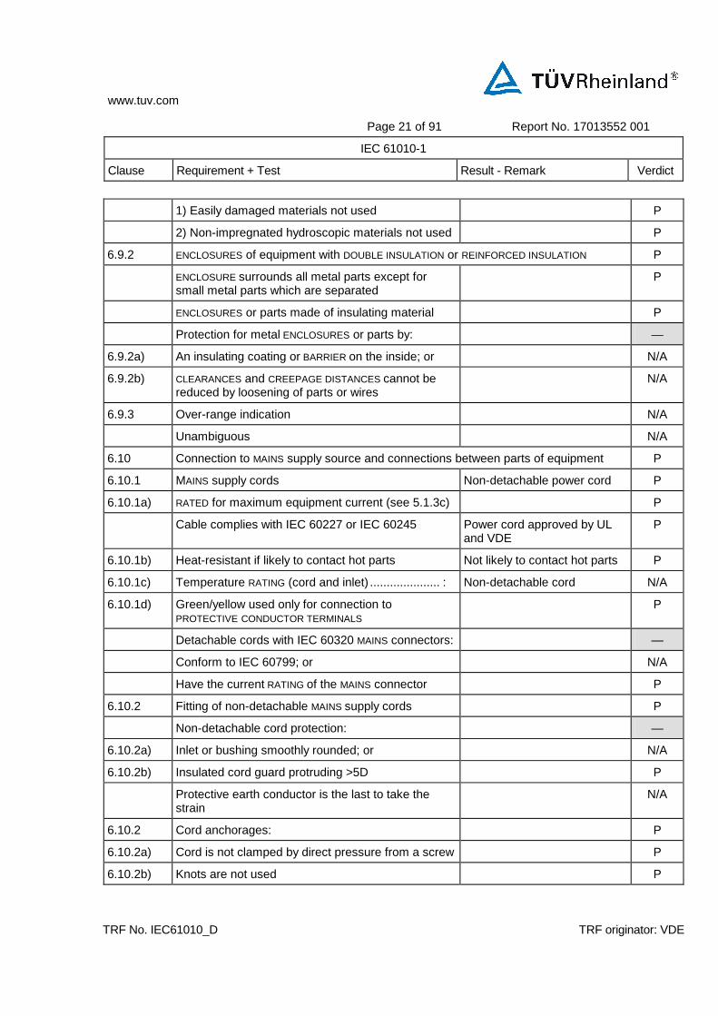
6.9.2 ENCLOSURES of equipment with DOUBLE INSULATION or REINFORCED INSULATION P
ENCLOSURE surrounds all metal parts except for small metal parts which are separated
P
ENCLOSURES or parts made of insulating material P
Protection for metal ENCLOSURES or parts by: —
6.9.2a) An insulating coating or BARRIER on the inside; or N/A
6.9.2b) CLEARANCES and CREEPAGE DISTANCES cannot be reduced by loosening of parts or wires
N/A
6.9.3 Over-range indication N/A
Unambiguous N/A
6.10 Connection to MAINS supply source and connections between parts of equipment P
6.10.1 MAINS supply cords Non-detachable power cord P
6.10.1a) RATED for maximum equipment current (see 5.1.3c) P
Cable complies with IEC 60227 or IEC 60245 Power cord approved by UL and VDE
P
6.10.1b) Heat-resistant if likely to contact hot parts Not likely to contact hot parts P
6.10.1c) Temperature RATING (cord and inlet) ..................... : Non-detachable cord N/A
6.10.1d) Green/yellow used only for connection to PROTECTIVE CONDUCTOR TERMINALS
P
Detachable cords with IEC 60320 MAINS connectors: —
Conform to IEC 60799; or N/A
Have the current RATING of the MAINS connector P
6.10.2 Fitting of non-detachable MAINS supply cords P
Non-detachable cord protection: —
6.10.2a) Inlet or bushing smoothly rounded; or N/A
6.10.2b) Insulated cord guard protruding >5D P
Protective earth conductor is the last to take the strain
N/A
6.10.2 Cord anchorages: P
6.10.2a) Cord is not clamped by direct pressure from a screw P
6.10.2b) Knots are not used P
www.tuv.com
Page 22 of 91 Report No. 17013552 001
IEC 61010-1
Clause Requirement + Test Result - Remark Verdict
TRF No. IEC61010_D TRF originator: VDE
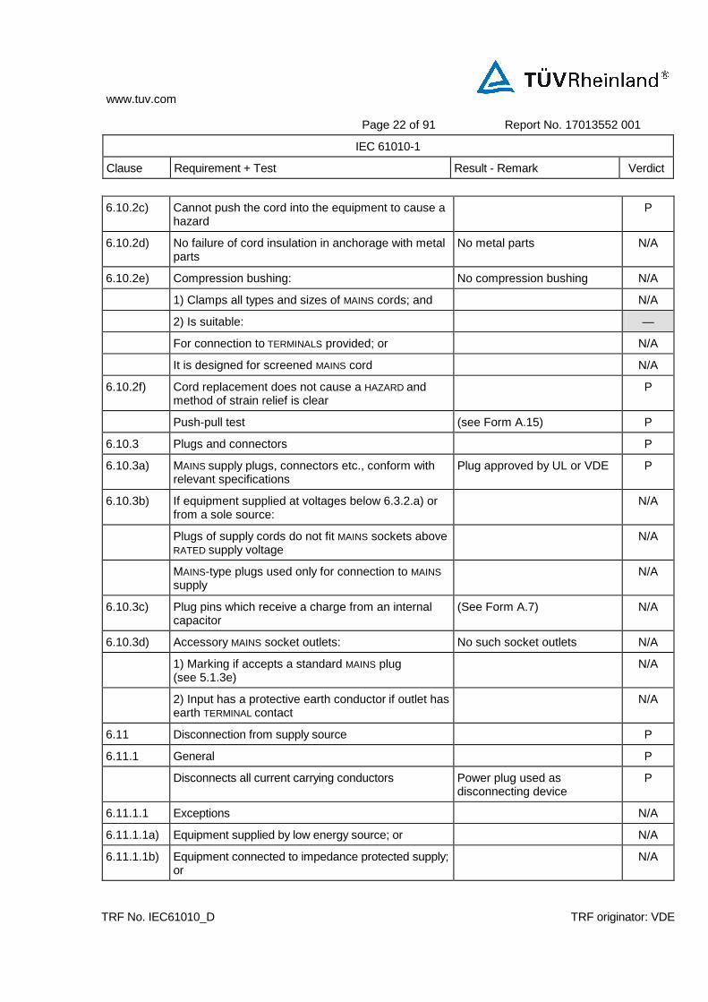
6.10.2c) Cannot push the cord into the equipment to cause a hazard
P
6.10.2d) No failure of cord insulation in anchorage with metal parts
No metal parts N/A
6.10.2e) Compression bushing: No compression bushing N/A
1) Clamps all types and sizes of MAINS cords; and N/A
2) Is suitable: —
For connection to TERMINALS provided; or N/A
It is designed for screened MAINS cord N/A
6.10.2f) Cord replacement does not cause a HAZARD and method of strain relief is clear
P
Push-pull test (see Form A.15) P
6.10.3 Plugs and connectors P
6.10.3a) MAINS supply plugs, connectors etc., conform with relevant specifications
Plug approved by UL or VDE P
6.10.3b) If equipment supplied at voltages below 6.3.2.a) or from a sole source:
N/A
Plugs of supply cords do not fit MAINS sockets above RATED supply voltage
N/A
MAINS-type plugs used only for connection to MAINS supply
N/A
6.10.3c) Plug pins which receive a charge from an internal capacitor
(See Form A.7) N/A
6.10.3d) Accessory MAINS socket outlets: No such socket outlets N/A
1) Marking if accepts a standard MAINS plug (see 5.1.3e)
N/A
2) Input has a protective earth conductor if outlet has earth TERMINAL contact
N/A
6.11 Disconnection from supply source P
6.11.1 General P
Disconnects all current carrying conductors Power plug used as disconnecting device
P
6.11.1.1 Exceptions N/A
6.11.1.1a) Equipment supplied by low energy source; or N/A
6.11.1.1b) Equipment connected to impedance protected supply; or
N/A

www.tuv.com
Page 23 of 91 Report No. 17013552 001
IEC 61010-1
Clause Requirement + Test Result - Remark Verdict
TRF No. IEC61010_D TRF originator: VDE
6.11.1.1c) Equipment constitues an impedance protected load N/A
6.11.2 Requirements according to type of equipment P
6.11.2.1 PERMANENTLY CONNECTED EQUIPMENT and multi-phase equipment:
N/A
Employs switch or circuit-breaker Not permanently connected or multi-phase equipment
N/A
If switch or circuit-breaker is not part of the equipment, documentation specifies:
—
6.11.2.1a) Switch or circuit-breaker to be included in building installation
N/A
6.11.2.1b) Location N/A
6.11.2.1c) Marking N/A
6.11.2.2 Single-phase cord-connected equipment P
Equipment is provided with: —
6.11.2.2a) Switch or circuit-breaker; or N/A
6.11.2.2b) Appliance coupler (disconnectable without TOOL); or N/A
6.11.2.2c) Separable plug (without locking device) P
6.11.2.3 HAZARDS arising from function No hazards arising from function
N/A
Emergency switch N/A
Emergency switch ≤ 1 m from the moving part N/A
6.11.3 Disconnecting devices Plug used as disconnecting device
P
Electrically close to the supply P
6.11.3.1 Switches and circuit-breakers N/A
When used as disconnection device: —
Meets IEC 60947-1 and IEC 60947-3 N/A
Marked to indicate function N/A
Not incorporated in MAINS cord N/A
Does not interrupt protective earth conductor N/A
If has other contacts meets separation requirements of 6.6 and 6.7
N/A
6.11.3.2 Appliance couplers and plugs P
Where an appliance coupler or separable plug is used as the disconnecting device (see 6.11.2.2):
—

www.tuv.com
Page 24 of 91 Report No. 17013552 001
IEC 61010-1
Clause Requirement + Test Result - Remark Verdict
TRF No. IEC61010_D TRF originator: VDE
Readily identifiable and easily reached by the OPERATOR
P
Single-phase PORTABLE EQUIPMENT cord length not more than 3 m
P
Protective earth conductor connected first and disconnected last
P
7 PROTECTION AGAINST MECHANICAL HAZARDS P
7.1 General P
Conformity is checked by 7.2 to 7.6 P
7.2 Moving parts The moving parts can shake, no hazards could occur
P
Moving parts not able to crush, etc. (see also 6.11.2.3)
N/A
If OPERATOR access permitted: —
7.2a) Access requires TOOL N/A
7.2b) Statement about training N/A
7.2c) Warning markings or symbol 14 N/A
7.3 Stability P
Marking of non-automatic means N/A
Conformity tests: —
7.3a) 10° tilt test P
7.3b) Multi-directional force test N/A
7.3c) Downward force test Not floor standing N/A
7.4 Provisions for lifting and carrying N/A
Handles or grips withstand four times weight N/A
Equipment more than 18 kg : Less than 18kg —
Has means for lifting or carrying; or N/A
Directions in documentation N/A
7.5 Wall mounting N/A
Mounting brackets withstand four times weight N/A
7.6 Expelled parts Expelled parts could not happen
N/A
Equipment contains or limits the energy N/A
www.tuv.com
Page 25 of 91 Report No. 17013552 001
IEC 61010-1
Clause Requirement + Test Result - Remark Verdict
TRF No. IEC61010_D TRF originator: VDE
Protection not removable without the aid of a TOOL N/A
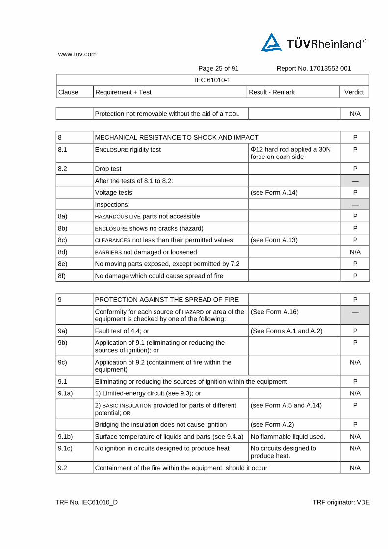
8 MECHANICAL RESISTANCE TO SHOCK AND IMPACT P
8.1 ENCLOSURE rigidity test Φ12 hard rod applied a 30N force on each side
P
8.2 Drop test P
After the tests of 8.1 to 8.2: —
Voltage tests (see Form A.14) P
Inspections: —
8a) HAZARDOUS LIVE parts not accessible P
8b) ENCLOSURE shows no cracks (hazard) P
8c) CLEARANCES not less than their permitted values (see Form A.13) P
8d) BARRIERS not damaged or loosened N/A
8e) No moving parts exposed, except permitted by 7.2 P
8f) No damage which could cause spread of fire P
9 PROTECTION AGAINST THE SPREAD OF FIRE P
Conformity for each source of HAZARD or area of the equipment is checked by one of the following:
(See Form A.16)
—
9a) Fault test of 4.4; or (See Forms A.1 and A.2) P
9b) Application of 9.1 (eliminating or reducing the sources of ignition); or
P
9c) Application of 9.2 (containment of fire within the equipment)
N/A
9.1 Eliminating or reducing the sources of ignition within the equipment P
9.1a) 1) Limited-energy circuit (see 9.3); or N/A
2) BASIC INSULATION provided for parts of different potential; OR
(see Form A.5 and A.14) P
Bridging the insulation does not cause ignition (see Form A.2) P
9.1b) Surface temperature of liquids and parts (see 9.4.a) No flammable liquid used. N/A
9.1c) No ignition in circuits designed to produce heat No circuits designed to produce heat.
N/A
9.2 Containment of the fire within the equipment, should it occur N/A

www.tuv.com
Page 26 of 91 Report No. 17013552 001
IEC 61010-1
Clause Requirement + Test Result - Remark Verdict
TRF No. IEC61010_D TRF originator: VDE
9.2a) Energizing of the equipment is controlled by an OPERATOR held switch
N/A
9.2b) Enclosure is conform with constructional requirements of 9.2.1; and
See below 9.2.1 N/A
Requirements of 9.4b) or c) are met N/A
9.2.1 Constructional requirements N/A
9.2.1a) Insulated wires have flammability classification FV1 or better
(see Table: 3 or Form A.17) N/A
Connectors and insulating material have flammability classification FV2 or better
(see Table: 3 or Form A.17) N/A
9.2.1b) The enclosure is constructed as follows: N/A
1) Bottom constructed with: —
No openings; or N/A
Extent as specified in figure 7; or N/A
Baffles as specified in figure 6; or N/A
Perforated as specified in Table 12; or N/A
Metal screen with a mesh N/A
2) Sides have no openings as specified in figure 7 N/A
3) Material of ENCLOSURE and any baffle or flame barrier is made of:
—
Metal (except magnesium); or N/A
Non metallic materials have flammability classification FV1 or better
(see Table: 3 or Form A.17)
N/A
4) ENCLOSURE and any baffle or flame barrier have adequate rigidity
N/A
9.3 Limited-energy circuit N/A
9.3a) Potential not more than 30 r.m.s. and 42.4 V peak, or 60 V dc
(see Form A.18) N/A
9.3b) Current limited by one of following means: N/A
1) Inherently or by impedance; or N/A
2) Overcurrent protective device; or N/A
3) A regulating network limits also in SINGLE FAULT CONDITION
N/A
9.3c) Is separated by at least BASIC INSULATION N/A
If overcurrent protective device used: —

www.tuv.com
Page 27 of 91 Report No. 17013552 001
IEC 61010-1
Clause Requirement + Test Result - Remark Verdict
TRF No. IEC61010_D TRF originator: VDE
Fuse or a non adjustable electromechanical device N/A
9.4 Requirements for equipment containing or using flammable liquids N/A
Flammable liquids contained in or specified for use with equipment do not cause spread of fire
No flammable liquids contained or used.
N/A
Risk is reduced to a tolerable level : (see Form A.19) —
9.4a) The temperature of surface or parts in contact with flammable liquids is 25 °C below fire point
N/A
9.4b) The quantity of liquid is limited N/A
9.4c) Flames are contained within the equipment N/A
Detailed instructions for risk-reduction provided N/A
9.5 Overcurrent protection Fuse used P
Devices not in the protective conductor P
Fuses or single-pole circuit-breakers not fitted in neutral (multi-phase)
Not fitted in neutral P
9.5.1 PERMANENTLY CONNECTED EQUIPMENT N/A
Overcurrent device: —
Fitted within the equipment; or N/A
Specified in manufacturer’s instructions N/A
9.5.2 Other equipment P
Protection within the equipment P
10 EQUIPMENT TEMPERATURE LIMITS AND RESISTANCE TO HEAT P
10.1 Surface temperature limits for protection against burns P
Easily touched surfaces within the limits (see Form A.20A) P
Heated surfaces necessary for functional reasons exceeding specified values:
—
Are recognizable as such by appearance or function; or
N/A
Are marked with symbol 13 N/A
Guards are not removable without TOOL N/A
10.2 Temperatures of windings P
Limits not exceeded in: (see Form A.20A)
—
NORMAL CONDITION P

www.tuv.com
Page 28 of 91 Report No. 17013552 001
IEC 61010-1
Clause Requirement + Test Result - Remark Verdict
TRF No. IEC61010_D TRF originator: VDE
SINGLE FAULT CONDITION P
10.3 Other temperature measurements P
Following measurements conducted if applicable: (see Form A.20A) —
10.3a) Value of 60 °C of field-wiring TERMINAL box not exceeded
N/A
10.3b) Surface of flammable liquids and parts in contact with this liquids
N/A
10.3c) Surface of non-metallic ENCLOSURES P
10.3d) Parts made of insulating material supporting parts connected to MAINS supply
P
10.3e) TERMINALS carrying a current more than 0.5 A P
10.4 Conduct of temperature test (see Form A20) P
10.5 Resistance to heat P
10.5.1 Integrity of CLEARANCE and CREEPAGE DISTANCES
(See Form A.13) P
10.5.2 Non-metallic ENCLOSURES Performed on plastic enclosure
P
After treatment:
—
No HAZARDOUS LIVE parts ACCESSIBLE; P
Tests of 8.1 and 8.2 (See Form A.13) P
In case of doubt, tests of 6.8 (without humidity preconditioning)
(See Form A.14) P
10.5.3 Insulating material P
10.5.3a) Parts supporting parts connected to MAINS supply P
10.5.3b) TERMINALS carrying a current more than 0.5 A P
Examination of material data; or N/A
in case of doubt: —
1) Ball pressure test; or P
2) Vicat softening testof ISO 306 N/A
11 PROTECTION AGAINST HAZARDS FROM FLUIDS P
11.1 General P
11.2 Cleaning (See Form A.23) P
11.3 Spillage (See Form A.23) P

www.tuv.com
Page 29 of 91 Report No. 17013552 001
IEC 61010-1
Clause Requirement + Test Result - Remark Verdict
TRF No. IEC61010_D TRF originator: VDE
11.4 Overflow (See Form A.23)
P
11.5 Battery electrolyte N/A
Battery electrolyte leakage presents no hazard No battery used N/A
11.6 Specially protected equipment (See Form A.23) N/A
11.7 Fluid pressure and leakage N/A
11.7.1 Maximum pressure................................................... : (See Form A.24) N/A
Maximum pressure of any part does not exceed PRATED
N/A
11.7.2 Leakage and rupture at high pressure (See Form A.24) N/A
Test to IEC 60335 (refrigeration only) N/A
11.7.3 Leakage from low-pressure parts (See Form A.24) N/A
11.7.4 Overpressure safety device N/A
Does not operate in NORMAL USE N/A
Meets ISO 4126-1; and N/A
It is conform with: —
11.7.4a) Connected as close as possible to parts intended to be protected
N/A
11.7.4b) Easy access for inspection, maintenance and repair N/A
11.7.4c) Adjustment only with TOOL N/A
11.7.4d) No discharge towards person N/A
11.7.4e) No HAZARD from deposit of discharged material N/A
11.7.4f) Adequate discharge capacity N/A
11.7.4g) No shut-off valve between overpressure safety device and protected parts
N/A
12 PROTECTION AGAINST RADIATION, INCLUDING LASER SOURCES, AND AGAINST SONIC AND ULTRASONIC PRESSURE
N/A
12.1 General N/A
Equipment provides protection N/A
12.2 Equipment producing ionizing radiation N/A
12.2.1 Ionizing radiation (See Form A.25) N/A
12.2.2 Accelerated electrons No accelerated electrons N/A
12.3 Ultra-violet (UV) radiation N/A

www.tuv.com
Page 30 of 91 Report No. 17013552 001
IEC 61010-1
Clause Requirement + Test Result - Remark Verdict
TRF No. IEC61010_D TRF originator: VDE
No unintentional and HAZARDOUS escape of UV radiation
No UV used N/A
12.4 Micro-wave radiation N/A
Power density does not exceed 10 W/m2 ...................: N/A
12.5 Sonic and ultrasonic pressure N/A
12.5.1 Sound level (See Form A.26) N/A
12.5.2 Ultrasonic pressure (See Form A.26) N/A
12.6 Laser sources (IEC 60825-1) No laser source N/A
13 PROTECTION AGAINST LIBERATED GASES, EXPLOSION AND IMPLOSION N/A
13.1 Poisonous and injurious gases No such gases N/A
Attached data/test reports demonstrate conformity N/A
13.2 Explosion and implosion N/A
13.2.1 Components No components liable to explode
N/A
Components liable to explode: —
Pressure release device provided; or N/A
Apparatus incorporates OPERATOR protection (see also 7.6)
N/A
Pressure release device: —
Discharge without danger N/A
Cannot be obstructed N/A
13.2.2 Batteries and battery charging N/A
If explosion or fire hazard could occur: —
Protection incorporated in the equipment; or N/A
Instructions specify batteries with built-in protection N/A
In case of wrong type of battery used: —
No HAZARD; or N/A
Warning by marking and within instructions N/A
Equipment with means to charge rechargeable batteries:
—
Warning against the charging of non-rechargeable batteries; and
N/A
Type of rechargeable battery indicated; or N/A

www.tuv.com
Page 31 of 91 Report No. 17013552 001
IEC 61010-1
Clause Requirement + Test Result - Remark Verdict
TRF No. IEC61010_D TRF originator: VDE
Symbol 14 used N/A
Battery compartment design (See Form A.27)
N/A
Single component failure N/A
Polarity reversal test N/A
13.2.3 Implosion of cathode ray tubes N/A
If maximum face dimensions > 160 mm ....................: —
Intrinsically protected and correctly mounted; or N/A
ENCLOSURE provides protection: N/A
If non-intrinsically protected: —
Screen not removable without TOOL N/A
If glass screen, not in contact with surface of tube N/A
13.2.4 Equipment RATED for high pressure (See 11.7) N/A
14 COMPONENTS P
14.1 General P
Where safety is involved, components meet relevant requirements
(see Table: 3) P
14.2 Motors P
14.2.1 Motor temperatures P
Does not present a HAZARD when stopped or prevented form starting; or
(See Form A.20) P
Protected by overtemperature or thermal protection device conform with 14.3
Over temperature device used P
14.2.2 Series excitation motors No such excitation motors used.
N/A
Connected direct to device, if overspeeding causes a HAZARD
N/A
14.3 Overtemperature protection devices P
Devices operating in a SINGLE FAULT CONDITION (See Form A.28) P
14.3a) Reliable function is ensured P
14.3b) RATED to interrupt maximum current and voltage P
14.3c) Does not operate in NORMAL USE P
14.4 Fuse holders No fuse holder used N/A

www.tuv.com
Page 32 of 91 Report No. 17013552 001
IEC 61010-1
Clause Requirement + Test Result - Remark Verdict
TRF No. IEC61010_D TRF originator: VDE
No access to HAZARDOUS LIVE parts N/A
14.5 Mains voltage selecting devices N/A
Accidental change not possible N/A
14.6 HIGH INTEGRITY components No such components N/A
Used in applicable positions (see Table 3) N/A
Conforms with IEC publications N/A
Single electronic device not used N/A
14.7 Mains transformers tested outside equipment (see Forms A.29 and A.30)
N/A
14.8 Printed circuit boards P
Data shows conformity with FV-1 of IEC 60707 or better; or
V-0 P
Test shows conformity with FV-1 of IEC 60707 or better; or
See Form A.17 N/A
Thin film flexible PCB with limited-energy circuit used
N/A
14.9 Circuits or components used as transient overvoltage limiting devices
N/A
After test, no sign of overload or degradation N/A
15 PROTECTION BY INTERLOCKS No interlocks N/A
15.1 General . N/A
Interlocks are designed to remove a hazard before OPERATOR exposed
N/A
15.2 Prevention of reactivation N/A
15.3 Reliability N/A
Single fault unlikely to occur; or N/A
Cannot cause a HAZARD N/A
16 TEST AND MEASUREMENT EQUIPMENT N/A
16.1 Current measuring circuits (see Form A.31)
N/A
16.2 Multifunction meters and similar equipment (see Form A.32) N/A
No HAZARD from: —
www.tuv.com
Page 33 of 91 Report No. 17013552 001
IEC 61010-1
Clause Requirement + Test Result - Remark Verdict
TRF No. IEC61010_D TRF originator: VDE
RATED input voltage combinations N/A
Settings of functions N/A
Settings of range controls N/A
ANNEX F ROUTINE TESTS N/A
Manufacturer’s declaration N/A

www.tuv.com
Page 34 of 91 Report No. 17013552 001
IEC 61010-1
Clause Requirement + Test Result - Remark Verdict
TRF No. IEC61010_D TRF originator: VDE
4.4.2 TABLE: Summary of SINGLE FAULT CONDITIONS Form A.1 P
Subclause Title Does not apply
Carried out
Comments
4.4.2.1 PROTECTIVE IMPEDANCE X --
4.4.2.2 Protective conductor -- X see Form A.8
4.4.2.3 Equipment or parts for short-term or intermittent operation
-- X Thermostat operated during continuous operation
4.4.2.4 Motors -- X Motor blocked
4.4.2.5 Capacitors X --
4.4.2.6 Mains transformers Attach drawing of MAINS Txs showing all protective devices (see Forms A.29 and A.30)
X --
4.4.2.7 Outputs X --
4.4.2.8 Equipment for more than one supply X --
4.4.2.9 Cooling
– air holes closed -- X
– fans stopped X --
– coolant stopped X --
4.4.2.10 Heating devices
– timer overridden X --
– temperature controller overridden X --
– loss of cooling liquid X --
– overfilled or empty or both X --
4.4.2.11 Insulation between circuits and parts X --
4.4.2.12 Interlocks X --
List below all SINGLE FAULT CONDITIONS not covered by 4.4.2.1 to 4.4.2.12:
Supplementary information :( see Form A.2 for details of tests) All single fault tests performed on both EU type and NA type
www.tuv.com
Page 35 of 91 Report No. 17013552 001
IEC 61010-1
Clause Requirement + Test Result - Remark Verdict
TRF No. IEC61010_D TRF originator: VDE
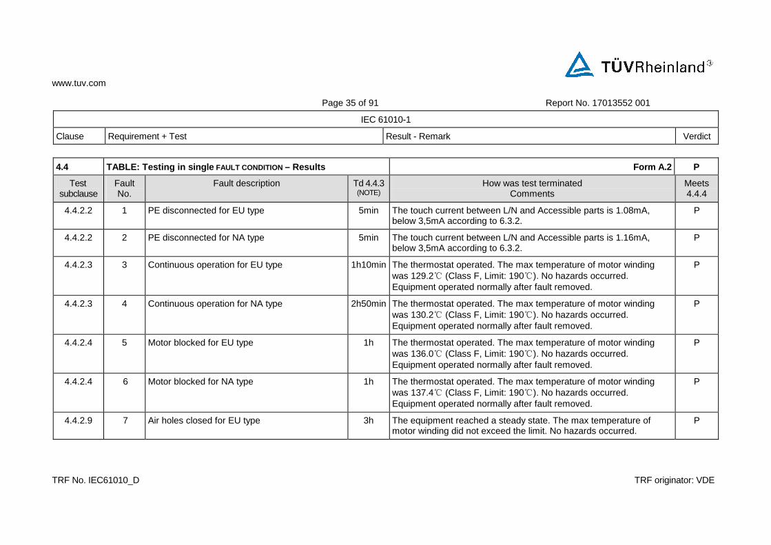
4.4 TABLE: Testing in single FAULT CONDITION – Results Form A.2 P
Test subclause
Fault No.
Fault description Td 4.4.3 (NOTE)
How was test terminated Comments
Meets 4.4.4
4.4.2.2 1 PE disconnected for EU type 5min The touch current between L/N and Accessible parts is 1.08mA, below 3,5mA according to 6.3.2.
P
4.4.2.2 2 PE disconnected for NA type 5min The touch current between L/N and Accessible parts is 1.16mA, below 3,5mA according to 6.3.2.
P
4.4.2.3 3 Continuous operation for EU type 1h10min The thermostat operated. The max temperature of motor winding was 129.2 (Class F, Limit: 190). No hazards occurred. Equipment operated normally after fault removed.
P
4.4.2.3 4 Continuous operation for NA type 2h50min The thermostat operated. The max temperature of motor winding was 130.2 (Class F, Limit: 190). No hazards occurred. Equipment operated normally after fault removed.
P
4.4.2.4
5 Motor blocked for EU type 1h The thermostat operated. The max temperature of motor winding was 136.0 (Class F, Limit: 190). No hazards occurred. Equipment operated normally after fault removed.
P
4.4.2.4 6 Motor blocked for NA type 1h The thermostat operated. The max temperature of motor winding was 137.4 (Class F, Limit: 190). No hazards occurred. Equipment operated normally after fault removed.
P
4.4.2.9 7 Air holes closed for EU type 3h The equipment reached a steady state. The max temperature of motor winding did not exceed the limit. No hazards occurred.
P
www.tuv.com
Page 36 of 91 Report No. 17013552 001
IEC 61010-1
Clause Requirement + Test Result - Remark Verdict
TRF No. IEC61010_D TRF originator: VDE
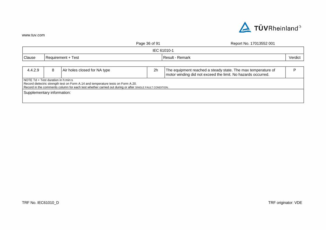
4.4.2.9 8 Air holes closed for NA type 2h The equipment reached a steady state. The max temperature of motor winding did not exceed the limit. No hazards occurred.
P
NOTE Td = Test duration in h:min:s Record dielectric strength test on Form A.14 and temperature tests on Form A.20. Record in the comments column for each test whether carried out during or after SINGLE FAULT CONDITION.
Supplementary information:

www.tuv.com
Page 37 of 91 Report No. 17013552 001
IEC 61010-1
Clause Requirement + Test Result - Remark Verdict
TRF No. IEC61010_D TRF originator: VDE
5.1.3c) TABLE: Mains supply Form A.3 P
Marked rating ........... : For EU: 220-230VAC
For NA: 110-120VAC
—
Phase ........................ : Single —
Frequency ................ : For EU: 50Hz
For NA: 60Hz
—
Current .................... : --A —
Power ...................... : 60W —
Power ...................... : --VA —
Test Voltage Frequency Current Power in Power in Comments
No. V Hz A W VA
Vortex Mixer MX-S
1 253 50 -- 54 -- Steady condition
2 198 50 -- 26 -- Steady condition
3 132 60 -- 47.5 -- Steady condition
4 99 60 -- 25 -- Steady condition
Note: Measurements are only required for marked ratings.
Supplementary information:
Equipment working according to the user manual at normal working condition and procedure.
www.tuv.com
Page 38 of 91 Report No. 17013552 001
IEC 61010-1
Clause Requirement + Test Result - Remark Verdict
TRF No. IEC61010_D TRF originator: VDE
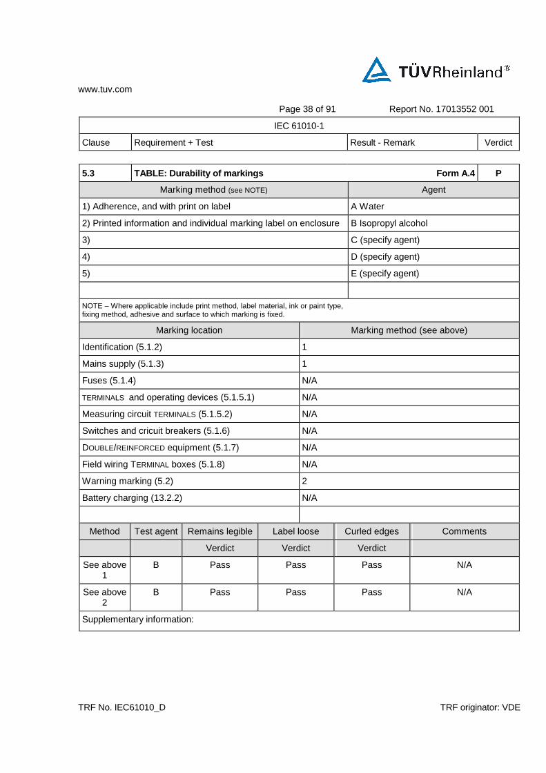
5.3 TABLE: Durability of markings Form A.4 P
Marking method (see NOTE) Agent
1) Adherence, and with print on label A Water
2) Printed information and individual marking label on enclosure B Isopropyl alcohol
3) C (specify agent)
4) D (specify agent)
5) E (specify agent)
NOTE – Where applicable include print method, label material, ink or paint type, fixing method, adhesive and surface to which marking is fixed.
Marking location Marking method (see above)
Identification (5.1.2) 1
Mains supply (5.1.3) 1
Fuses (5.1.4) N/A
TERMINALS and operating devices (5.1.5.1) N/A
Measuring circuit TERMINALS (5.1.5.2) N/A
Switches and cricuit breakers (5.1.6) N/A
DOUBLE/REINFORCED equipment (5.1.7) N/A
Field wiring TERMINAL boxes (5.1.8) N/A
Warning marking (5.2) 2
Battery charging (13.2.2) N/A
Method Test agent Remains legible Label loose Curled edges Comments
Verdict Verdict Verdict
See above 1
B Pass Pass Pass N/A
See above 2
B Pass Pass Pass N/A
Supplementary information:

www.tuv.com
Page 39 of 91 Report No. 17013552 001
IEC 61010-1
Clause Requirement + Test Result - Remark Verdict
TRF No. IEC61010_D TRF originator: VDE
6 TABLE: Protection against electric shock - Block diagram of system Form A.5 P
Pollution degree.......: II Measurement category (overvoltage category)...: II P
Location or Insulation type
Maximum working
CREEPAGE DISTANCE (NOTE 3)
CLEARANCE (NOTE 3)
Test voltage
Comments
description (NOTE 1) voltage (NOTE 2)
PWB mm
CTI Other mm
CTI Mm (NOTE 2) V
L/N-Plastic enclosure RI
120VAC (for NA) -- -- 12 100 6 1344
Required cl.=1.0mm cr.=3.2mm
L/N-Metal enclosure BI
120VAC (for NA) -- -- 12 100 6 840
Required cl.=0.5mm cr.=1.6mm
L/N-Mixing head RI
120VAC (for NA) -- -- 12 100 6 1344
Required cl.=1.0mm cr.=3.2mm
L/N-Metal core of mixing head
BI 120VAC (for NA) -- -- 12 100 6 840
Required cl.=0.5mm cr.=1.6mm
L/N-Plastic enclosure RI
230VAC (for EU) -- -- 12 100 6 2224
Required cl.=3.0mm cr.=6.0mm
L/N-Metal enclosure BI
230VAC (for EU) -- -- 12 100 6 1390
Required cl.=1.5mm cr.=3.0mm

www.tuv.com
Page 40 of 91 Report No. 17013552 001
IEC 61010-1
Clause Requirement + Test Result - Remark Verdict
TRF No. IEC61010_D TRF originator: VDE
6 TABLE: Protection against electric shock - Block diagram of system Form A.5 P
L/N-Mixing head RI
230VAC (for EU) -- -- 12 100 6 2224
Required cl.=3.0mm cr.=6.0mm
L/N-Metal core of mixing head
BI 230VAC (for EU) -- -- 12 100 6 1390
Required cl.=1.5mm cr.=3.0mm
NOTE 1 – Type of insulation: NOTE 2 - Types of voltage NOTE 3 - INSTALLATION CATEGORIES
BI = BASIC INSULATION Peak impulse test voltage (pulse) (OVERVOLTAGE CATEGORIES) DI = DOUBLE INSULATION r.m.s. or POLLUTION DEGREES which differ from PI = PROTECTIVE IMPEDANCE d.c. these should be shown under "Comments". RI = Reinforced INSULATION peak SI = Supplementary INSULATION
Supplementary Information:
1. The EU type and the NA type have the same internal structure. The clearance and creepage value are also the same.
2. Clearance requirements as below:
For voltage line-to-neutral a.c. r.m.s. 120V/230V
Basic insulation requirement of clearance is 0.5mm/1.5mm Reinforced insulation requirement of clearance is 1mm/3mm
3. Creepage requirements as below:
For voltage line-to-neutral a.c. r.m.s. 110V/230V, Pollution degree 2 and Material group III considered.
Basic insulation requirement of Creepage is 1.6mm/3mm Reinforced insulation requirement of Creepage is 3.2mm/6mm
www.tuv.com
Page 41 of 91 Report No. 17013552 001
IEC 61010-1
Clause Requirement + Test Result - Remark Verdict
TRF No. IEC61010_D TRF originator: VDE
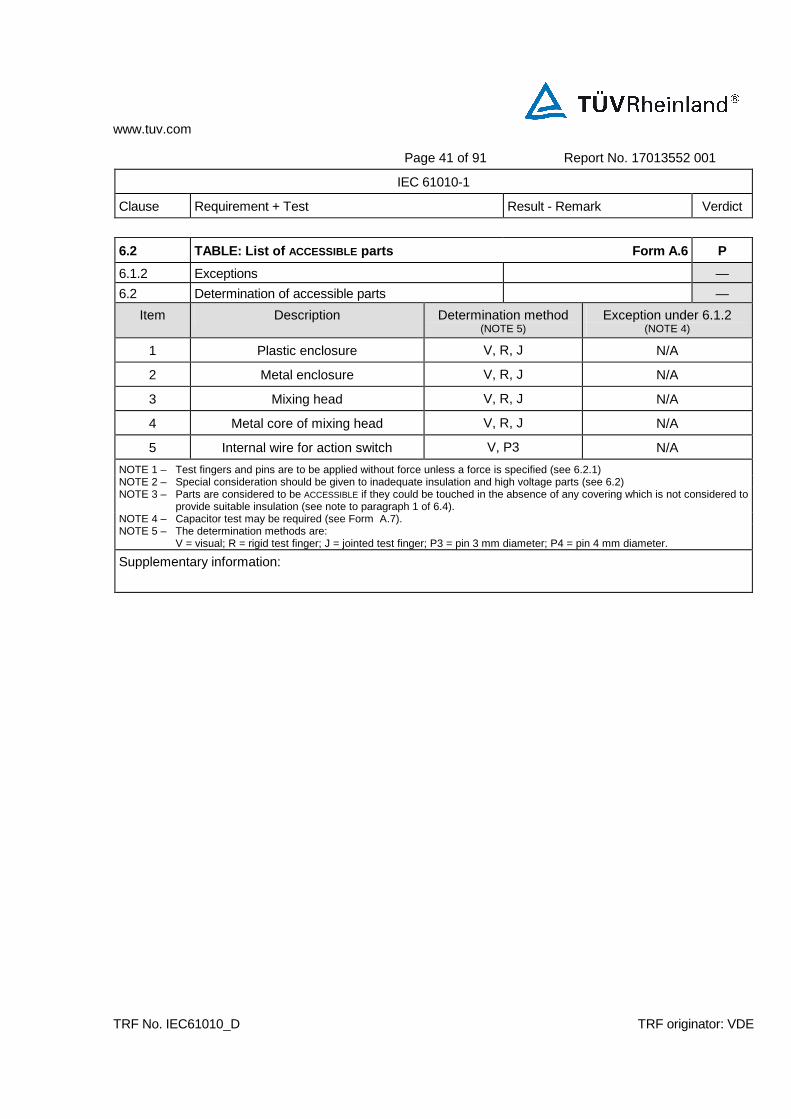
6.2 TABLE: List of ACCESSIBLE parts Form A.6 P
6.1.2 Exceptions —
6.2 Determination of accessible parts —
Item Description Determination method (NOTE 5)
Exception under 6.1.2 (NOTE 4)
1 Plastic enclosure V, R, J N/A
2 Metal enclosure V, R, J N/A
3 Mixing head V, R, J N/A
4 Metal core of mixing head V, R, J N/A
5 Internal wire for action switch V, P3 N/A
NOTE 1 – Test fingers and pins are to be applied without force unless a force is specified (see 6.2.1) NOTE 2 – Special consideration should be given to inadequate insulation and high voltage parts (see 6.2) NOTE 3 – Parts are considered to be ACCESSIBLE if they could be touched in the absence of any covering which is not considered to
provide suitable insulation (see note to paragraph 1 of 6.4). NOTE 4 – Capacitor test may be required (see Form A.7). NOTE 5 – The determination methods are:
V = visual; R = rigid test finger; J = jointed test finger; P3 = pin 3 mm diameter; P4 = pin 4 mm diameter.
Supplementary information:
www.tuv.com
Page 42 of 91 Report No. 17013552 001
IEC 61010-1
Clause Requirement + Test Result - Remark Verdict
TRF No. IEC61010_D TRF originator: VDE
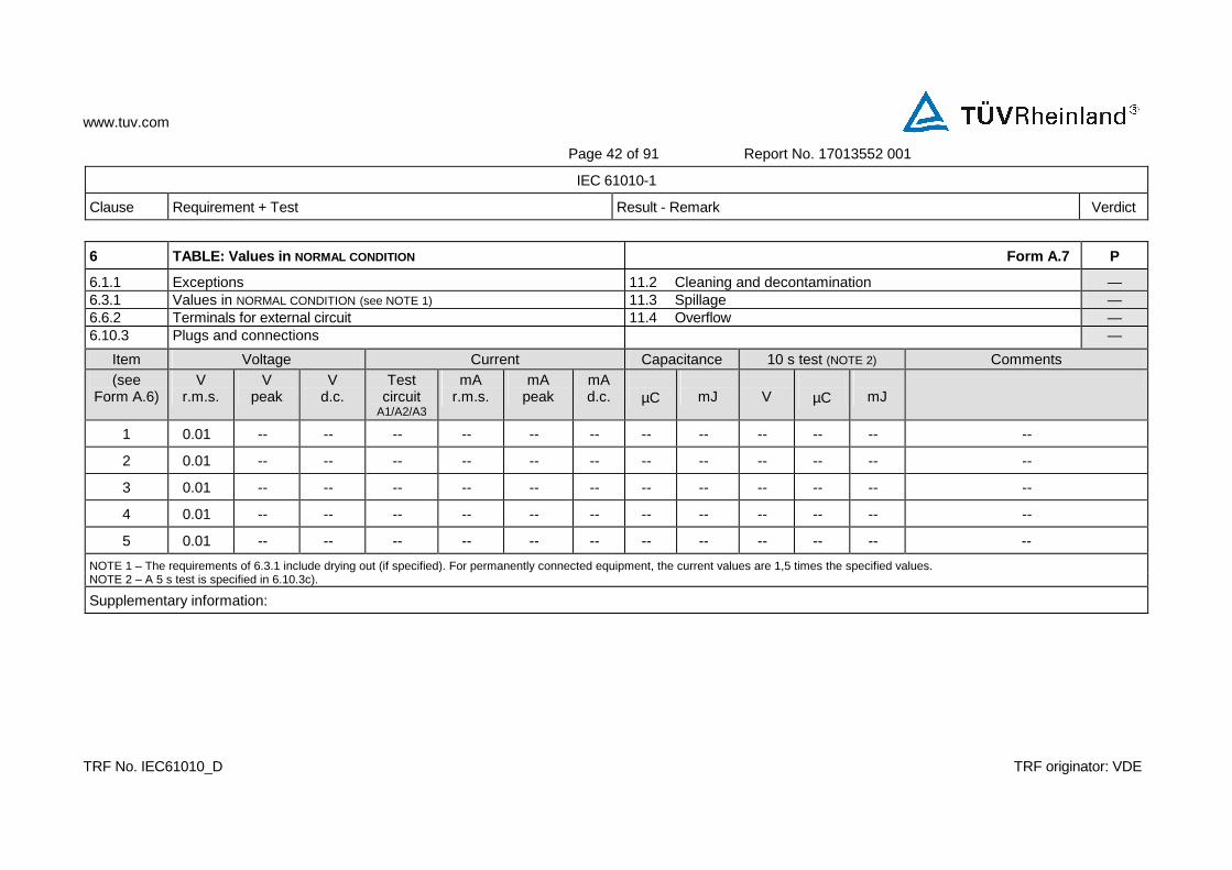
6 TABLE: Values in NORMAL CONDITION Form A.7 P
6.1.1 Exceptions 11.2 Cleaning and decontamination — 6.3.1 Values in NORMAL CONDITION (see NOTE 1) 11.3 Spillage — 6.6.2 Terminals for external circuit 11.4 Overflow — 6.10.3 Plugs and connections —
Item Voltage Current Capacitance 10 s test (NOTE 2) Comments (see
Form A.6) V
r.m.s. V
peak V
d.c. Test
circuit A1/A2/A3
mA r.m.s.
mA peak
mA d.c.
µC
mJ
V
µC
mJ
1 0.01 -- -- -- -- -- -- -- -- -- -- -- --
2 0.01 -- -- -- -- -- -- -- -- -- -- -- --
3 0.01 -- -- -- -- -- -- -- -- -- -- -- --
4 0.01 -- -- -- -- -- -- -- -- -- -- -- --
5 0.01 -- -- -- -- -- -- -- -- -- -- -- --
NOTE 1 – The requirements of 6.3.1 include drying out (if specified). For permanently connected equipment, the current values are 1,5 times the specified values. NOTE 2 – A 5 s test is specified in 6.10.3c).
Supplementary information:

www.tuv.com
Page 43 of 91 Report No. 17013552 001
IEC 61010-1
Clause Requirement + Test Result - Remark Verdict
TRF No. IEC61010_D TRF originator: VDE
6.3.2 TABLE: Values in SINGLE FAULT CONDITION Form A.8 P
Item Subclause and
Voltage Transient (see NOTE)
Current Capacitance
(See Form A.6)
fault No. (see FormA.2)
V r.m.s.
V peak
V d.c.
V
s
Test circuit
A1/A2/A3
mA r.m.s.
mA peak
mA d.c.
µF (NOTE)
Comments
Item 2, 4 1-2 0.01 -- -- -- -- A2 1.08 (EU) 1.16 (NA)
-- -- -- Limit for current level in single fault condition is 3.5mA r.m.s
Item 1, 3, 5 3-8 0.01 -- -- -- -- -- -- -- -- -- --
Item 1-5 1-8 0.01 -- -- -- -- -- -- -- -- -- --
NOTE – Transient voltages must be below the limits given from Figure 1 and the capacitance below the limits from figure 2 of IEC 61010-1.
Supplementary information:

www.tuv.com
Page 44 of 91 Report No. 17013552 001
IEC 61010-1
Clause Requirement + Test Result - Remark Verdict
TRF No. IEC61010_D TRF originator: VDE
6.5.1.1 TABLE: Cross-sectional area of bonding cond uctors Form A.9 P
Conductor location Cross-sectional area mm2
Verdict
Power cord: L, N, G (for EU) 3G 0.75 mm² P
Power cord: L, N, G (For NA) 3G 14AWG P
6.5.1.2 TABLE: Tighting torque test P
Conductor location Size of Screw Tighting torque
Nm
Verdict
Protective earthing terminal M4 1.2 P
Supplementary information:
www.tuv.com
Page 45 of 91 Report No. 17013552 001
IEC 61010-1
Clause Requirement + Test Result - Remark Verdict
TRF No. IEC61010_D TRF originator: VDE
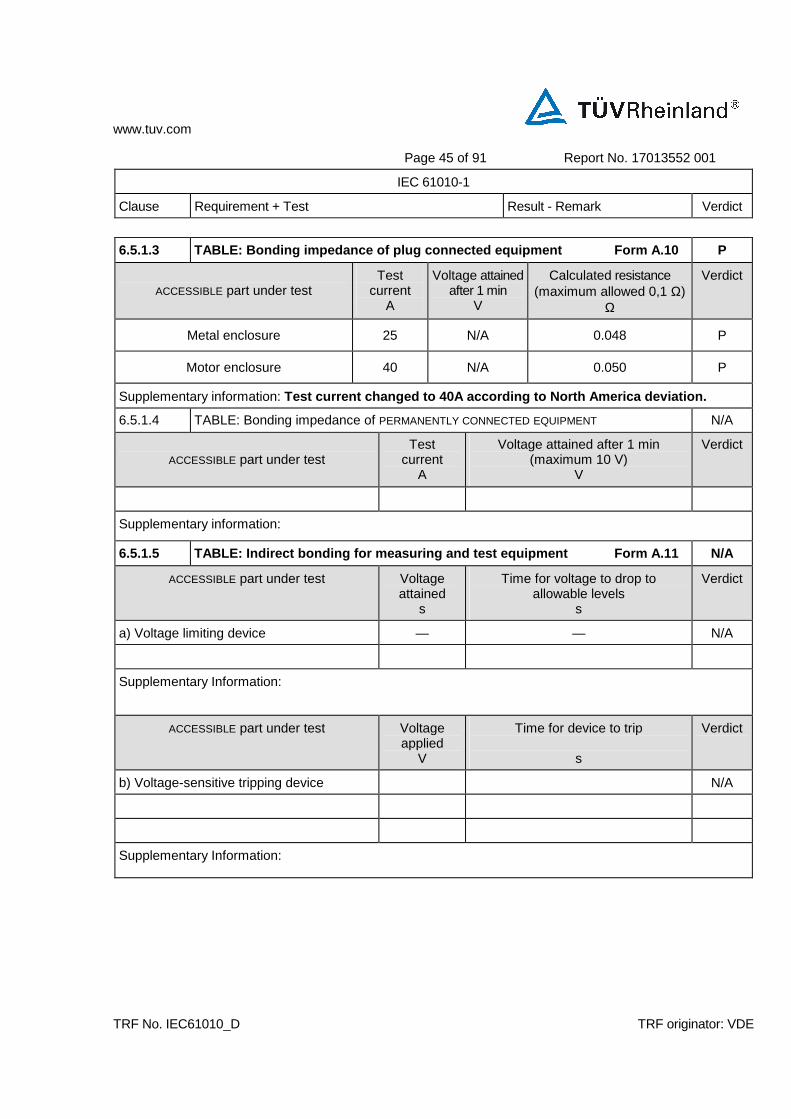
6.5.1.3 TABLE: Bonding impedance of plug connected equipment Form A.10 P
ACCESSIBLE part under test
Test current
A
Voltage attained after 1 min
V
Calculated resistance (maximum allowed 0,1 Ω)
Ω
Verdict
Metal enclosure 25 N/A 0.048 P
Motor enclosure 40 N/A 0.050 P
Supplementary information: Test current changed to 40A according to North Ame rica deviation.
6.5.1.4 TABLE: Bonding impedance of PERMANENTLY CONNECTED EQUIPMENT N/A
ACCESSIBLE part under test
Test current
A
Voltage attained after 1 min (maximum 10 V)
V
Verdict
Supplementary information:
6.5.1.5 TABLE: Indirect bonding for measuring and t est equipment Form A.11 N/A
ACCESSIBLE part under test Voltage attained
s
Time for voltage to drop to allowable levels
s
Verdict
a) Voltage limiting device — — N/A
Supplementary Information:
ACCESSIBLE part under test Voltage applied
V
Time for device to trip s
Verdict
b) Voltage-sensitive tripping device N/A
Supplementary Information:

www.tuv.com
Page 46 of 91 Report No. 17013552 001
IEC 61010-1
Clause Requirement + Test Result - Remark Verdict
TRF No. IEC61010_D TRF originator: VDE
6.5.3 TABLE: PROTECTIVE IMPEDANCE Form A.12 N/A
A high INTEGRITY single component
Component Location Comments
A combination of components
Component Location Comments
Note:
A combination of BASIC INSULATION and a current or voltage limiting device
Component Location Comments
Supplementary information:

www.tuv.com
Page 47 of 91 Report No. 17013552 001
IEC 61010-1
Clause Requirement + Test Result - Remark Verdict
TRF No. IEC61010_D TRF originator: VDE
6.7 TABLE: C LEARANCES and CREEPAGE DISTANCES Form A.13 P
8 Mechanical resistance to shock and impact P
10.5.1 Integrity of CLEARANCES and CREEPAGE DISTANCES P Location Measured
(initial – 6.7) Verdict Mechanical tests (note) Test at
max. Measured after test
(if required) Verdict
(see Form A.5)
CREEPAGE DISTANCE
CLEARANCE Applied force
Rigidity (8.1)
Drop (8.2)
RATED ambient
CREEPAGE DISTANCE
CLEARANCE Comments
mm mm (6.7) N Static Dynamic Normal Hand-held/ Plug-in
(10.5.1) mm mm
L/N-Plastic enclosure
12 6 P 30N 30N 5J Yes N/A 40oC 12 6 P --
Motor winding-
Core
12 6 P 30N 30N 5J Yes N/A 40oC 12 6 P --
Motor winding -Mixing head
12 6 P 30N 30N 5J Yes N/A 40oC 12 6 P --
Motor winding -
Metal core of mixing
head
12 6 P 30N 30N 5J Yes N/A 40oC 12 6 P --
NOTE – Refer to Form A.14 for dielectric strength tests following the above tests.

www.tuv.com
Page 48 of 91 Report No. 17013552 001
IEC 61010-1
Clause Requirement + Test Result - Remark Verdict
TRF No. IEC61010_D TRF originator: VDE
6.7 TABLE: C LEARANCES and CREEPAGE DISTANCES Form A.13 P
8 Mechanical resistance to shock and impact P
10.5.1 Integrity of CLEARANCES and CREEPAGE DISTANCES P Location Measured
(initial – 6.7) Verdict Mechanical tests (note) Test at
max. Measured after test
(if required) Verdict
(see Form A.5)
CREEPAGE DISTANCE
CLEARANCE Applied force
Rigidity (8.1)
Drop (8.2)
RATED ambient
CREEPAGE DISTANCE
CLEARANCE Comments
mm mm (6.7) N Static Dynamic Normal Hand-held/ Plug-in
(10.5.1) mm mm
Supplementary information:
www.tuv.com
Page 49 of 89 Report No. 17013552 001
IEC 61010-1
Clause Requirement + Test Result - Remark Verdict
TRF No. IEC61010_D TRF originator: VDE
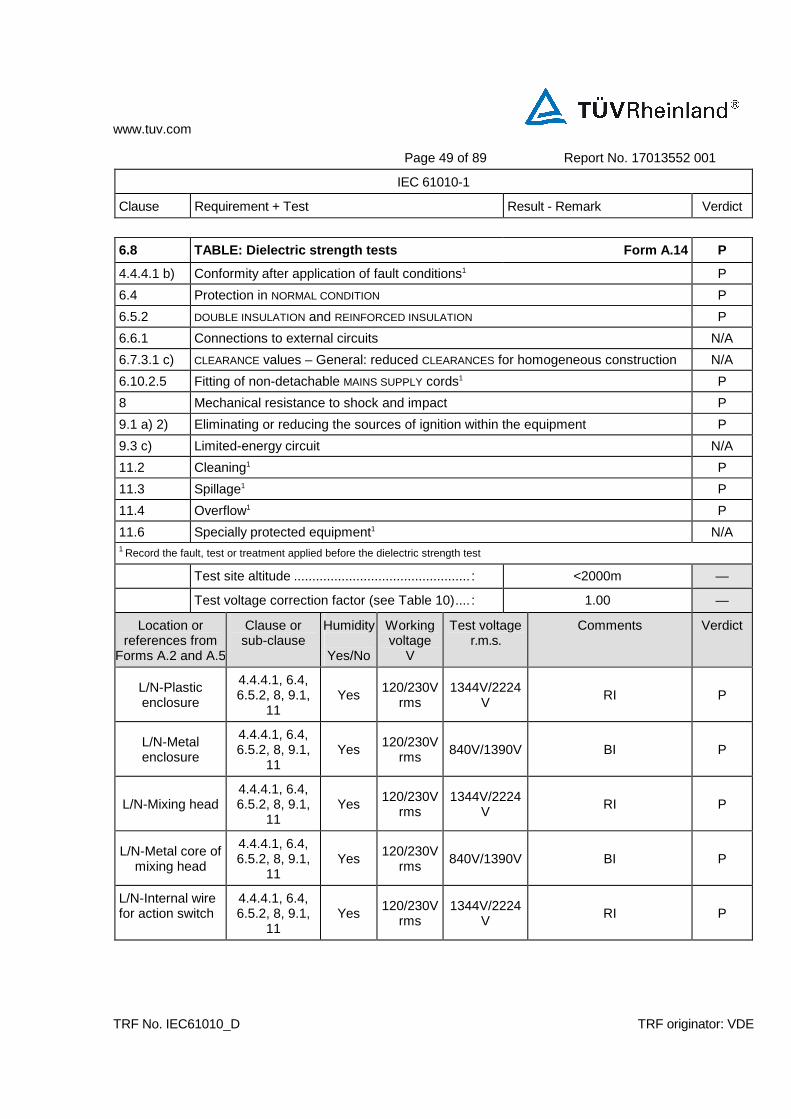
6.8 TABLE: Dielectric strength tests Form A.14 P
4.4.4.1 b) Conformity after application of fault conditions1 P
6.4 Protection in NORMAL CONDITION P
6.5.2 DOUBLE INSULATION and REINFORCED INSULATION P
6.6.1 Connections to external circuits N/A
6.7.3.1 c) CLEARANCE values – General: reduced CLEARANCES for homogeneous construction N/A
6.10.2.5 Fitting of non-detachable MAINS SUPPLY cords1 P
8 Mechanical resistance to shock and impact P
9.1 a) 2) Eliminating or reducing the sources of ignition within the equipment P
9.3 c) Limited-energy circuit N/A
11.2 Cleaning1 P
11.3 Spillage1 P
11.4 Overflow1 P
11.6 Specially protected equipment1 N/A 1 Record the fault, test or treatment applied before the dielectric strength test
Test site altitude ................................................ : <2000m —
Test voltage correction factor (see Table 10).... : 1.00 —
Location or references from
Forms A.2 and A.5
Clause or sub-clause
Humidity
Yes/No
Working voltage
V
Test voltage r.m.s.
Comments Verdict
L/N-Plastic enclosure
4.4.4.1, 6.4, 6.5.2, 8, 9.1,
11 Yes
120/230Vrms
1344V/2224V RI P
L/N-Metal enclosure
4.4.4.1, 6.4, 6.5.2, 8, 9.1,
11 Yes
120/230Vrms 840V/1390V BI P
L/N-Mixing head 4.4.4.1, 6.4, 6.5.2, 8, 9.1,
11 Yes
120/230Vrms
1344V/2224V RI P
L/N-Metal core of mixing head
4.4.4.1, 6.4, 6.5.2, 8, 9.1,
11 Yes
120/230Vrms 840V/1390V BI P
L/N-Internal wire for action switch
4.4.4.1, 6.4, 6.5.2, 8, 9.1,
11 Yes
120/230Vrms
1344V/2224V RI P
www.tuv.com
Page 49 of 89 Report No. 17013552 001
IEC 61010-1
Clause Requirement + Test Result - Remark Verdict
TRF No. IEC61010_D TRF originator: VDE
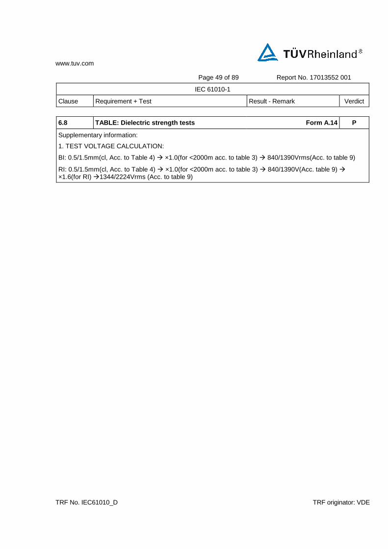
6.8 TABLE: Dielectric strength tests Form A.14 P
Supplementary information:
1. TEST VOLTAGE CALCULATION:
BI: 0.5/1.5mm(cl, Acc. to Table 4) ×1.0(for <2000m acc. to table 3) 840/1390Vrms(Acc. to table 9)
RI: 0.5/1.5mm(cl, Acc. to Table 4) ×1.0(for <2000m acc. to table 3) 840/1390V(Acc. table 9) ×1.6(for RI) 1344/2224Vrms (Acc. to table 9)
www.tuv.com
Page 49 of 89 Report No. 17013552 001
IEC 61010-1
Clause Requirement + Test Result - Remark Verdict
TRF No. IEC61010_D TRF originator: VDE
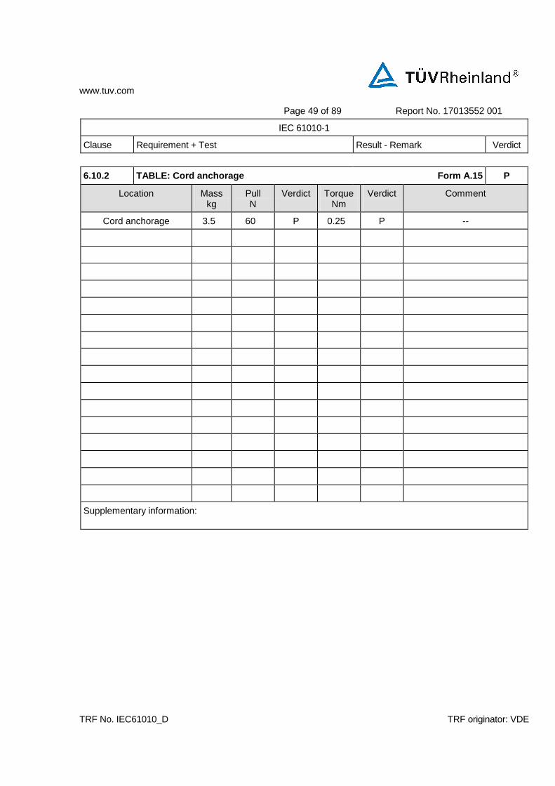
6.10.2 TABLE: Cord anchorage Form A.15 P
Location Mass kg
Pull N
Verdict
Torque Nm
Verdict
Comment
Cord anchorage 3.5 60 P 0.25 P --
Supplementary information:
www.tuv.com
Page 52 of 91 Report No. 17013552 001
IEC 61010-1
Clause Requirement + Test Result - Remark Verdict
TRF No. IEC61010_D TRF originator: VDE
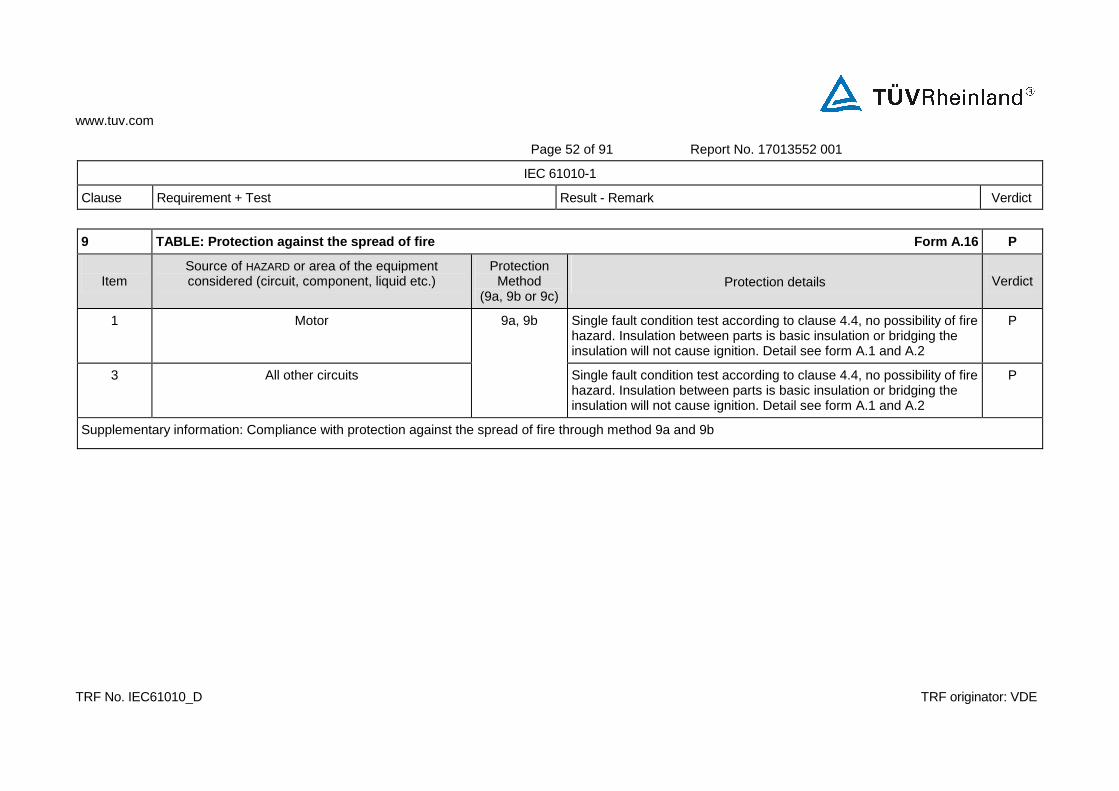
9 TABLE: Protection against the spread of fire Form A.16 P
Item
Source of HAZARD or area of the equipment considered (circuit, component, liquid etc.)
Protection Method
(9a, 9b or 9c)
Protection details
Verdict
1 Motor Single fault condition test according to clause 4.4, no possibility of fire hazard. Insulation between parts is basic insulation or bridging the insulation will not cause ignition. Detail see form A.1 and A.2
P
3 All other circuits
9a, 9b
Single fault condition test according to clause 4.4, no possibility of fire hazard. Insulation between parts is basic insulation or bridging the insulation will not cause ignition. Detail see form A.1 and A.2
P
Supplementary information: Compliance with protection against the spread of fire through method 9a and 9b
www.tuv.com
Page 53 of 91 Report No. 17013552 001
IEC 61010-1
Clause Requirement + Test Result - Remark Verdict
TRF No. IEC61010_D TRF originator: VDE
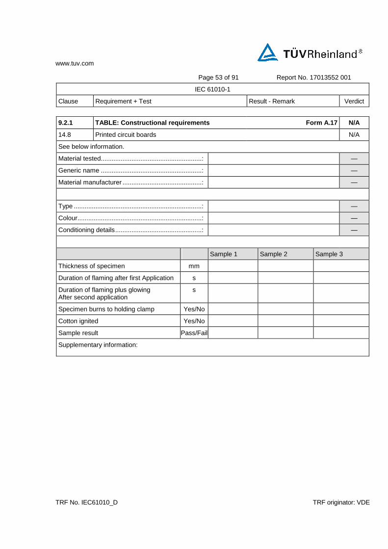
9.2.1 TABLE: Constructional requirements Form A.17 N/A
14.8 Printed circuit boards N/A
See below information.
Material tested........................................................: —
Generic name ........................................................: —
Material manufacturer ............................................: —
Type .......................................................................: —
Colour.....................................................................: —
Conditioning details................................................: —
Sample 1 Sample 2 Sample 3
Thickness of specimen mm
Duration of flaming after first Application s
Duration of flaming plus glowing After second application
s
Specimen burns to holding clamp Yes/No
Cotton ignited Yes/No
Sample result Pass/Fail
Supplementary information:
www.tuv.com
Page 54 of 91 Report No. 17013552 001
IEC 61010-1
Clause Requirement + Test Result - Remark Verdict
TRF No. IEC61010_D TRF originator: VDE
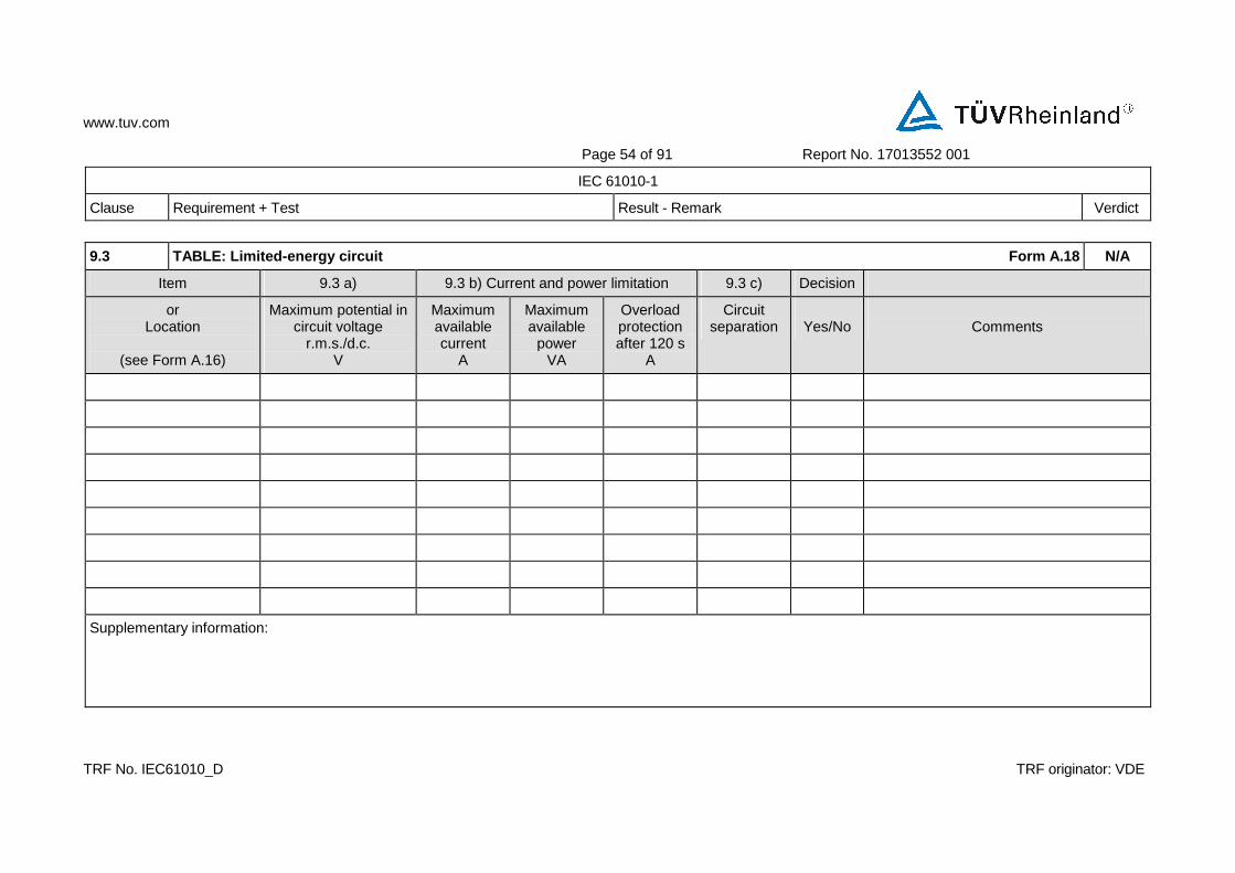
9.3 TABLE: Limited-energy circuit Form A.18 N/A
Item 9.3 a) 9.3 b) Current and power limitation 9.3 c) Decision
or Location
(see Form A.16)
Maximum potential in circuit voltage
r.m.s./d.c. V
Maximum available current
A
Maximum available
power VA
Overload protection after 120 s
A
Circuit separation
Yes/No
Comments
Supplementary information:

www.tuv.com
Page 55 of 91 Report No. 17013552 001
IEC 61010-1
Clause Requirement + Test Result - Remark Verdict
TRF No. IEC61010_D TRF originator: VDE
9.4 TABLE: Requirements for equipment containing or using flammable liquids Form A.19 N/A
Type of liquid 9.4 Flammable liquids Verdict
b) quantity c) Containment
Supplementary information:

www.tuv.com
Page 56 of 91 Report No. 17013552 001
IEC 61010-1
Clause Requirement + Test Result - Remark Verdict
TRF No. IEC61010_D TRF originator: VDE
10. TABLE : Temperature Measurements Form A.20A-1 P
10.1 Surface temperature limits - NORMAL CONDITION P
10.2 Temperature of windings- NORMAL CONDITION P
10.3 Other temperature measurements P
Operating conditions: Normal Operation according to the user manual
Frequency .......... : 50 Hz Test room ambient temperature (ta) .. : 26.2 °C
Voltage............... : 253 V Test duration ..................................... : h 30 min
Part / Location tm
°C tc
°C tmax
°C Verdict Comments
Normal operation
1. Power plug 27.1 40.9 80 P --
2. Internal wire 53.6 67.4 105 P --
3. Connector for Motor 55.9 69.7 85 P --
4. Inductance (L1) 27.3 41.1 70 P --
5. X capacitor (C1) 66.7 80.5 85 P --
6. PCB 63.9 77.7 130 P --
7. Transistor (Q1) 71.5 85.3 105 P --
8. Fuse (F1) 61.2 75 -- P --
9. Motor winding 107.2 121 155 P --
10. Bobbin of motor 99.4 113.2 155 P --
11. Button 29.3 43.1 80 P --
NOTE 1 - tm = measured temperature tc = tm corrected (tm–ta+ 40 °°°°C or max. RATED ambient) tmax = maximum permitted temperature NOTE 2 - See also 14.1 with reference to component operating conditions NOTE 3 - Record values for NORMAL CONDITION and / or SINGLE FAULT CONDITION in this Form use additional form if necessary NOTE 4 - See Form A.20B for details of winding temperature measurements
Supplementary information:

www.tuv.com
Page 57 of 91 Report No. 17013552 001
IEC 61010-1
Clause Requirement + Test Result - Remark Verdict
TRF No. IEC61010_D TRF originator: VDE
10. TABLE : Temperature Measurements Form A.20A-2 P
10.1 Surface temperature limits - NORMAL CONDITION P
10.2 Temperature of windings- NORMAL CONDITION P
10.3 Other temperature measurements P
Operating conditions: Normal Operation according to the user manual
Frequency .......... : 50 Hz Test room ambient temperature (ta) .. : 24.7 °C
Voltage............... : 198 V Test duration ..................................... : h 30 min
Part / Location tm
°C tc
°C tmax
°C Verdict Comments
Normal operation
1. Power plug 27.9 43.2 80 P --
2. Internal wire 59.6 74.9 105 P --
3. Connector for Motor 65.4 80.7 85 P --
4. Inductance (L1) 28.6 43.9 70 P --
5. X capacitor (C1) 66.7 80.5 85 P --
6. PCB 70.7 86 130 P --
7. Transistor (Q1) 77.9 93.2 105 P --
8. Fuse (F1) 68.7 84 -- P --
9. Motor winding 91.9 107.2 155 P --
10. Bobbin of motor 87.7 103 155 P --
11. Button 36.2 51.5 80 P --
NOTE 1 - tm = measured temperature tc = tm corrected (tm–ta+ 40 °°°°C or max. RATED ambient) tmax = maximum permitted temperature NOTE 2 - See also 14.1 with reference to component operating conditions NOTE 3 - Record values for NORMAL CONDITION and / or SINGLE FAULT CONDITION in this Form use additional form if necessary NOTE 4 - See Form A.20B for details of winding temperature measurements
Supplementary information:
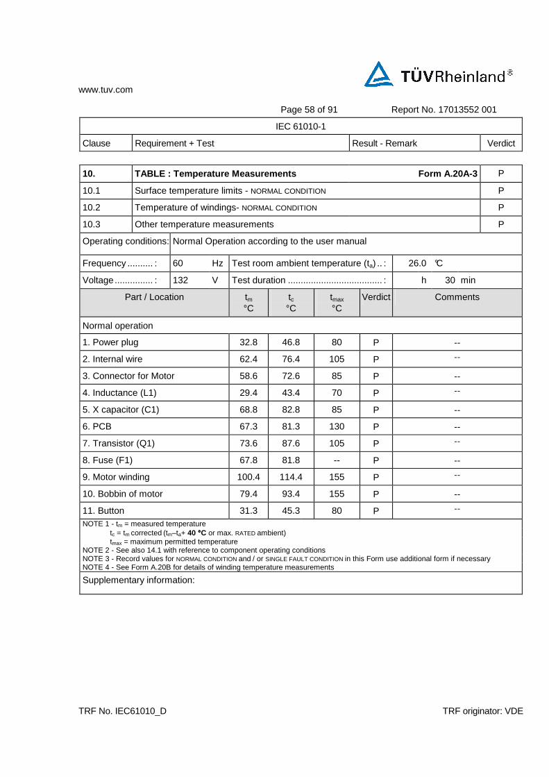
www.tuv.com
Page 58 of 91 Report No. 17013552 001
IEC 61010-1
Clause Requirement + Test Result - Remark Verdict
TRF No. IEC61010_D TRF originator: VDE
10. TABLE : Temperature Measurements Form A.20A-3 P
10.1 Surface temperature limits - NORMAL CONDITION P
10.2 Temperature of windings- NORMAL CONDITION P
10.3 Other temperature measurements P
Operating conditions: Normal Operation according to the user manual
Frequency .......... : 60 Hz Test room ambient temperature (ta) .. : 26.0 °C
Voltage............... : 132 V Test duration ..................................... : h 30 min
Part / Location tm
°C tc
°C tmax
°C Verdict Comments
Normal operation
1. Power plug 32.8 46.8 80 P --
2. Internal wire 62.4 76.4 105 P --
3. Connector for Motor 58.6 72.6 85 P --
4. Inductance (L1) 29.4 43.4 70 P --
5. X capacitor (C1) 68.8 82.8 85 P --
6. PCB 67.3 81.3 130 P --
7. Transistor (Q1) 73.6 87.6 105 P --
8. Fuse (F1) 67.8 81.8 -- P --
9. Motor winding 100.4 114.4 155 P --
10. Bobbin of motor 79.4 93.4 155 P --
11. Button 31.3 45.3 80 P --
NOTE 1 - tm = measured temperature tc = tm corrected (tm–ta+ 40 °°°°C or max. RATED ambient) tmax = maximum permitted temperature NOTE 2 - See also 14.1 with reference to component operating conditions NOTE 3 - Record values for NORMAL CONDITION and / or SINGLE FAULT CONDITION in this Form use additional form if necessary NOTE 4 - See Form A.20B for details of winding temperature measurements
Supplementary information:

www.tuv.com
Page 59 of 91 Report No. 17013552 001
IEC 61010-1
Clause Requirement + Test Result - Remark Verdict
TRF No. IEC61010_D TRF originator: VDE
10. TABLE : Temperature Measurements Form A.20A-4 P
10.1 Surface temperature limits - NORMAL CONDITION P
10.2 Temperature of windings- NORMAL CONDITION P
10.3 Other temperature measurements P
Operating conditions: Normal Operation according to the user manual
Frequency .......... : 60 Hz Test room ambient temperature (ta) .. : 28.1 °C
Voltage............... : 99 V Test duration ..................................... : h 30 min
Part / Location tm
°C tc
°C tmax
°C Verdict Comments
Normal operation
1. Power plug 28.6 40.5 80 P --
2. Internal wire 67.2 79.1 105 P --
3. Connector for Motor 64.2 76.1 85 P --
4. Inductance (L1) 29.6 41.5 70 P --
5. X capacitor (C1) 66.6 78.5 85 P --
6. PCB 65.7 77.6 130 P --
7. Transistor (Q1) 70 81.9 105 P --
8. Fuse (F1) 66 77.9 -- P --
9. Motor winding 81.6 93.5 155 P --
10. Bobbin of motor 72.1 84 155 P --
11. Button 34.7 46.6 80 P --
NOTE 1 - tm = measured temperature tc = tm corrected (tm–ta+ 40 °°°°C or max. RATED ambient) tmax = maximum permitted temperature NOTE 2 - See also 14.1 with reference to component operating conditions NOTE 3 - Record values for NORMAL CONDITION and / or SINGLE FAULT CONDITION in this Form use additional form if necessary NOTE 4 - See Form A.20B for details of winding temperature measurements
Supplementary information:

www.tuv.com
Page 60 of 91 Report No. 17013552 001
IEC 61010-1
Clause Requirement + Test Result - Remark Verdict
TRF No. IEC61010_D TRF originator: VDE
10.2 TABLE: Temperature of windings Resistance method Temperature Measurements
Form A.20B N/A
4.4.2.6 MAINS Transformers N/A
14.2.1 Motor temperatures N/A
Operating conditions:
Frequency ............... : Hz Test room ambient temperature (ta1/ta2)... : / °C (initial / final)
Voltage.................... : Test duration ............................................ : h min
Part / Designation Rcold
Ω Rwarm
Ω Current
A tr K
tc
°C tmax
°C Verdict Comments
NOTE 1- Rcold = initial resistance Rwarm = final resistance tr = temperature rise tc = tr corrected (tc= tr - ta2 - ta1 + [40 °C or max RATED ambient]) tmax = maximum permitted temperature NOTE 2 - Indicate insulation class (IEC 85) under comments (optional) NOTE 3 - Record values for NORMAL CONDITION and / or SINGLE FAULT CONDITION in this Form use additional form if necessary
Supplementary information: Temperature sensors was positioned on motor winding directly
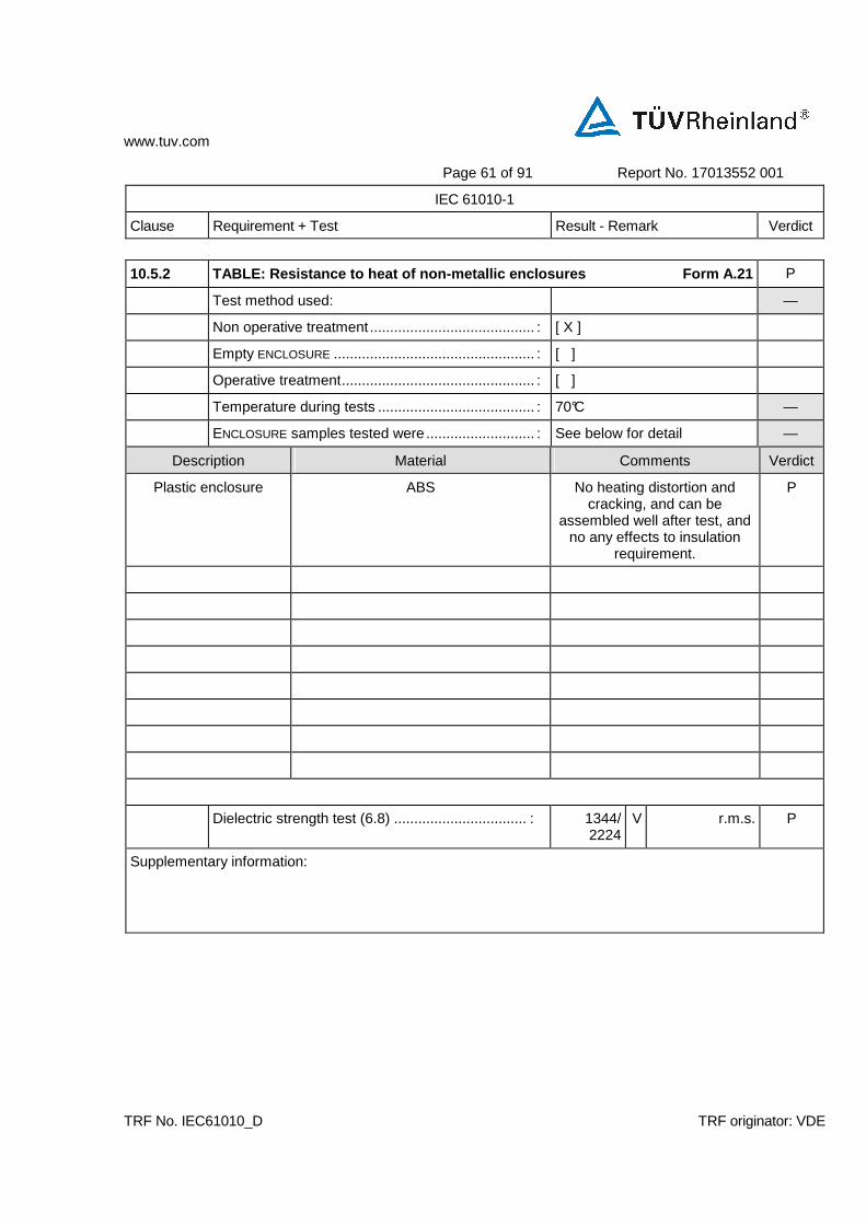
www.tuv.com
Page 61 of 91 Report No. 17013552 001
IEC 61010-1
Clause Requirement + Test Result - Remark Verdict
TRF No. IEC61010_D TRF originator: VDE
10.5.2 TABLE: Resistance to heat of non-metallic en closures Form A.21 P
Test method used: —
Non operative treatment ......................................... : [ X ]
Empty ENCLOSURE .................................................. : [ ]
Operative treatment................................................ : [ ]
Temperature during tests ....................................... : 70°C —
ENCLOSURE samples tested were ........................... : See below for detail —
Description Material Comments Verdict
Plastic enclosure ABS No heating distortion and cracking, and can be
assembled well after test, and no any effects to insulation
requirement.
P
Dielectric strength test (6.8) ................................. : 1344/ 2224
V r.m.s. P
Supplementary information:

www.tuv.com
Page 62 of 91 Report No. 17013552 001
IEC 61010-1
Clause Requirement + Test Result - Remark Verdict
TRF No. IEC61010_D TRF originator: VDE
10.5.3 TABLE: Insulating Materials Form A.22 P
10.5.3a) Ballpressure test P
Max. allowed impression diameter ......................... : 2 mm —
Part Test temperature °C
Impression Diameter (mm)
Verdict
Bobbin of motor winding 125 1.2 P
Supplementary information:
.
10.5.3b) Vicat softening test (ISO 306) N/A
Part Vicat softening temperature °C
Thickness of sample (mm)
Verdict
Supplementary information: N/A
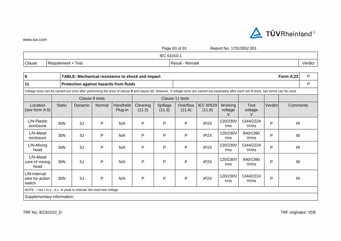
www.tuv.com
Page 63 of 91 Report No. 17013552 001
IEC 61010-1
Clause Requirement + Test Result - Remark Verdict
TRF No. IEC61010_D TRF originator: VDE
8 TABLE: Mechanical resistance to shock and impact Form A.23 P
11 Protection against hazards from fluids P
Voltage tests can be carried out once after performing the tests of clause 8 and clause 11. However, if voltage tests are carried out separately after each set of tests, two forms can be used.
Clause 8 tests Clause 11 tests
Location (see form A.5)
Static Dynamic Normal Handheld Plug-in
Cleaning (11.2)
Spillage (11.3)
Overflow (11.4)
IEC 60529 (11.6)
Working voltage
V
Test voltage
V
Verdict Comments
L/N-Plastic enclosure
30N 5J P N/A P P P IP2X 120/230Vrms
1344/2224 Vrms
P RI
L/N-Metal enclosure
30N 5J P N/A P P P IP2X 120/230Vrms
840/1390 Vrms
P BI
L/N-Mixing head
30N 5J P N/A P P P IP2X 120/230Vrms
1344/2224 Vrms
P RI
L/N-Metal core of mixing
head 30N 5J P N/A P P P IP2X
120/230Vrms
840/1390 Vrms P BI
L/N-Internal wire for action switch
30N 5J P N/A P P P IP2X 120/230V
rms 1344/2224
Vrms P RI
NOTE – Use r.m.s., d.c. or peak to indicate the used test voltage.
Supplementary information:
www.tuv.com
Page 64 of 91 Report No. 17013552 001
IEC 61010-1
Clause Requirement + Test Result - Remark Verdict
TRF No. IEC61010_D TRF originator: VDE
11.7.2 TABLE: Leakage and rupture at high pressure Form A.24 N/A
Part
Maximum permissible
working pressure
MPa
Test
pressure
MPa
Leakage
YES / NO
Burst
YES / NO
Comments
Supplementary information:
11.7.3 Leakage from low-pressure parts N/A
Part
Test pressure
MPa
Leakage
YES / NO
Comments
Supplementary information:
www.tuv.com
Page 65 of 91 Report No. 17013552 001
IEC 61010-1
Clause Requirement + Test Result - Remark Verdict
TRF No. IEC61010_D TRF originator: VDE
12.2.1 TABLE: Ionizing radiation Form A 25 N/A
Locations tested
Measured values µSv/h
Verdict
Comments
Supplementary information:

www.tuv.com
Page 66 of 91 Report No. 17013552 001
IEC 61010-1
Clause Requirement + Test Result - Remark Verdict
TRF No. IEC61010_D TRF originator: VDE
12.5.1 TABLE: Sound level Form A.26 N/A
Locations tested Measured values dBA
Calculated maximum sound pressure level
a)
b)
c)
d)
e)
Supplementary information:
12.5.2 Ultrasonic pressure N/A
Locations tested Measured values Comments
dB kHz
At OPERATOR’S normal position
At 1 m from the ENCLOSURE
a)
b)
c)
d)
e)
NOTE – No limit is specified at present, but a limit of 110 dB above the reference pressure value of 20 µPa is under consideration for applicable frequencies between 20 kHz and 100 kHz.
Supplementary information:
www.tuv.com
Page 67 of 91 Report No. 17013552 001
IEC 61010-1
Clause Requirement + Test Result - Remark Verdict
TRF No. IEC61010_D TRF originator: VDE
13.2.2 TABLE: Batteries Form A.27 N/A
Battery load and charging circuit diagram: N/A
Battery type............................................................. : —
Battery manufacturer/model/catalogue No............. : —
Battery ratings ........................................................ : —
Reverse polarity instalment test N/A
Single component failures Verdict
Component Open circuit Short circuit
Supplementary information:

www.tuv.com
Page 68 of 91 Report No. 17013552 001
IEC 61010-1
Clause Requirement + Test Result - Remark Verdict
TRF No. IEC61010_D TRF originator: VDE
14.3 TABLE: Overtemperature protection devices Form A.28 N/A
Reliability test
Component Type (note)
Verdict
Comments
Thermostat SR P --
NOTE:
NSR = non-self-resetting (10 times) NR = non-resetting (1 time) SR = self-resetting (200 times)
Supplementary information: Thermostat approved by VDE.

www.tuv.com
Page 69 of 91 Report No. 17013552 001
IEC 61010-1
Clause Requirement + Test Result - Remark Verdict
TRF No. IEC61010_D TRF originator: VDE
4.4.2.6 TABLE: Mains transformer Form A.29 N/A
4.4.2.6.1 Short circuit N/A
14.7.1 MAINS transformers tested outside equipment N/A
Type ............................ : —
Manufacturer............... : —
Test in equipment N/A
Test on bench N/A
Test repeated inside equipment (see 14.7) N/A
Optional – Insulation class (IEC 60085) of the lowest RATED winding ............ : —
Winding identification
Type of Protector for winding (Note 1)
Elapsed time
Current, A primary
secondary
Winding temperature, °C primary
(see Note 2) secondary
Tissue paper / cheesecloth OK ? (Pass / Fail)
Voltage tests (see Note 3)
primary to secondary V AC
Verdict
Note 1: Primary fuse - PF / ( ) A Secondary fuse - SF / ( ) A Overtemperature protection - OP / (100) °C Impedance protection - Z
Note 2: Indicate method of measurement TC = with thermocouple R = resistance method If resistance method is used,record resistance in cold and warm condition in FormA.20B!
Note 3: Record the voltage applied and the type of voltage (r.m.s. / d.c. / peak) and for results use NB = no breakdown or B = breakdown
Supplementary information:

www.tuv.com
Page 70 of 91 Report No. 17013552 001
IEC 61010-1
Clause Requirement + Test Result - Remark Verdict
TRF No. IEC61010_D TRF originator: VDE
4.4.2.6 TABLE: Mains transformer Form A.30 N/A
14.7.2 Overload tests (for mains transformers) N/A
Type ............................ : —
Manufacturer............... : —
Test in equipment
Test on bench
Test repeated inside equipment (see 14.7)
Optional – Insulation class (IEC 60085) of the lowest RATED winding ............ : —
Winding identification
Type of Protector for winding (Note 1)
Elapsed time
Current, A primary
secondary
Winding temperature, °C primary
(see Note 2) secondary
Tissue paper / cheesecloth OK ? (Pass / Fail)
Voltage tests (see Note 3)
primary to secondary ______ V ____
primary to core ______ V ____
secondary to secondary ______ V ____
secondary to core ______ V ____
Verdict
Note 1: Primary fuse - PF / ( ) A Secondary fuse - SF / ( ) A Overtemperature protection - OP / ( ) °C Impedance protection - Z
Note 2: Indicate method of measurement TC = with thermocouple R = resistance method If resistance method is used,record resistance in cold and warm condition in FormA.20B!
Note 3: Record the voltage applied and the type of voltage (r.m.s. / d.c. / peak) and for results use NB = no breakdown or B = breakdown
Supplementary information:
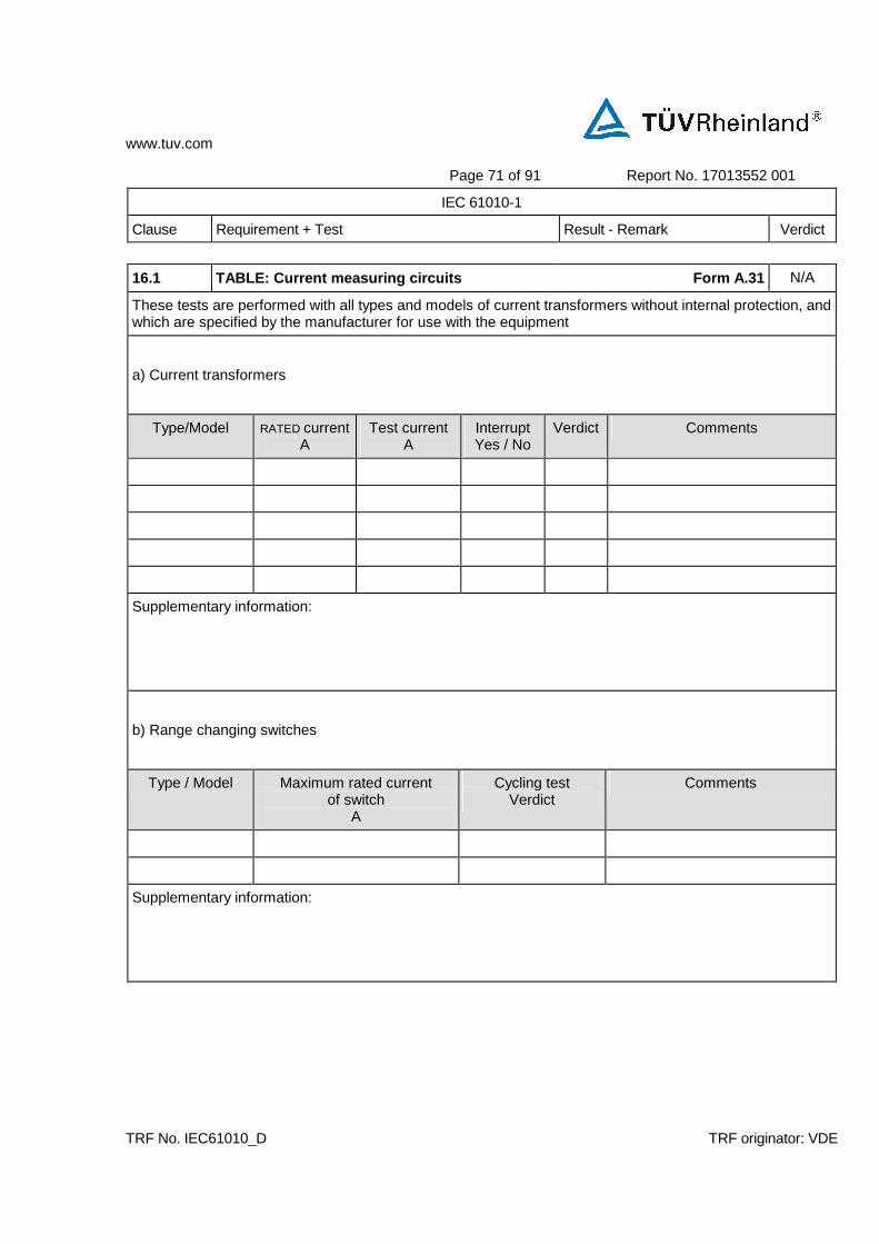
www.tuv.com
Page 71 of 91 Report No. 17013552 001
IEC 61010-1
Clause Requirement + Test Result - Remark Verdict
TRF No. IEC61010_D TRF originator: VDE
16.1 TABLE: Current measuring circuits Form A.31 N/A
These tests are performed with all types and models of current transformers without internal protection, and which are specified by the manufacturer for use with the equipment
a) Current transformers
Type/Model RATED current A
Test current A
Interrupt Yes / No
Verdict Comments
Supplementary information:
b) Range changing switches
Type / Model Maximum rated current of switch
A
Cycling test Verdict
Comments
Supplementary information:

www.tuv.com
Page 72 of 91 Report No. 17013552 001
IEC 61010-2-010
Clause Requirement + Test Result - Remark Verdict
TRF No. IEC61010_D TRF originator: VDE
16.2 TABLE: Multifunctional meters and similar equi pment Form A. 32 N/A
Operating conditions............................................... : —
Maximum RATED voltage applied (V) ...................... : —
Measurement category........................................... : —
Test source limit (KVA)........................................... : —
Function Range Verdict
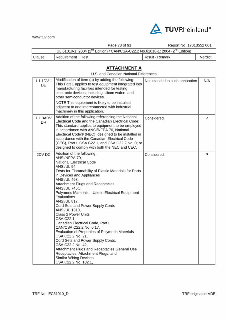
www.tuv.com
Page 73 of 91 Report No. 17013552 001
UL 61010-1: 2004 (2nd Edition) / CAN/CSA-C22.2 No.61010-1: 2004 (2nd Edition)
Clause Requirement + Test Result - Remark Verdict
TRF No. IEC61010_D TRF originator: VDE
ATTACHMENT A U.S. and Canadian National Differences
1.1.1DV.1 DE
Modification of item (a) by adding the following: This Part 1 applies to test equipment integrated into manufacturing facilities intended for testing electronic devices, including silicon wafers and other semiconductor devices.
NOTE This equipment is likely to be installed adjacent to and interconnected with industrial machinery in this application.
Not intended to such application N/A
1.1.3ADV DR
Addition of the following referencing the National Electrical Code and the Canadian Electrical Code: This standard applies to equipment to be employed in accordance with ANSI/NFPA 70, National Electrical Code® (NEC); designed to be installed in accordance with the Canadian Electrical Code (CEC), Part I, CSA C22.1, and CSA C22.2 No. 0; or designed to comply with both the NEC and CEC.
Considered. P
2DV DC Addition of the following: ANSI/NFPA 70, National Electrical Code ANSI/UL 94, Tests for Flammability of Plastic Materials for Parts in Devices and Appliances ANSI/UL 498, Attachment Plugs and Receptacles ANSI/UL 746C, Polymeric Materials – Use in Electrical Equipment Evaluations ANSI/UL 817, Cord Sets and Power Supply Cords ANSI/UL 1310, Class 2 Power Units CSA C22.1, Canadian Electrical Code, Part I CAN/CSA C22.2 No. 0.17, Evaluation of Properties of Polymeric Materials CSA C22.2 No. 21, Cord Sets and Power Supply Cords. CSA C22.2 No. 42, Attachment Plugs and Receptacles General Use Receptacles, Attachment Plugs, and Similar Wiring Devices CSA C22.2 No. 182.1,
Considered. P

www.tuv.com
Page 74 of 91 Report No. 17013552 001
UL 61010-1: 2004 (2nd Edition) / CAN/CSA-C22.2 No.61010-1: 2004 (2nd Edition)
Clause Requirement + Test Result - Remark Verdict
TRF No. IEC61010_D TRF originator: VDE
Industrial Type, Special Use Attachment Plugs, Receptacles, and Connectors CSA C22.2 No. 182.2, Industrial Locking Type, Special Use Attachment Plugs, Receptacles, and Connectors CSA C22.2 No. 182.3, Special Use Attachment Plugs, Receptacles, and Connectors CAN/CSA C22.2 No. 223, Power Supplies With Extra-Low Voltage Class 2 Outputs
P
4.4.4.1DV D2
Modification of item (b) in Clause 4.4.4.1: Replace the word conformity with humidity in the second sentence.
P
5.1.6DV D2 Modification: Replace the reference to Clause 6.11.2.5 with 6.11.3.1 in the first paragraph.
N/A
5.4.1DV D2 Modification by adding items (h) and (i) to Clause 5.4.1:
N/A
h) for equipment which for safety reasons requires specific probe assemblies, or probe assemblies with specific characteristics, the documentation shall indicate that probe assemblies which meet the manufacturer’s specifications shall be used.
Not for such application N/A
i) for equipment intended to detect the presence of a hazardous voltage, the instructions shall provide guidance on how to determine that the equipment is functioning correctly.
Not for such application N/A
6.3.1DV D2 Replacement of item (a) with the following: Voltage levels are 30 V r.m.s. and 42,4 V peak or 60 V d.c. For equipment RATED for use in WET LOCATIONS, the voltage levels are 16 V r.m.s. and 22,6 V peak or 35 V d.c.
Considered. P
6.3.2DV D2 Replacement of item (a) with the following: Voltage levels are 50 V r.m.s. and 70 V peak or 120 V d.c. For equipment RATED for use in WET LOCATIONS, the voltage levels are 33 V r.m.s. and 46,7 V peak or 70 V d.c. For temporary voltages, the levels are those of figure 1, measured across a 50 k resistor.
Considered. P
6.5.1.4DV D2
Modification: Add the following to the end of the last sentence of the second paragraph and shall not exceed 4 V a.c. r.m.s. or d.c for certification to Canadian requirements (in accordance with Clause 3.4.2.1 of CSA C22.2 No. 0.4).
N/A
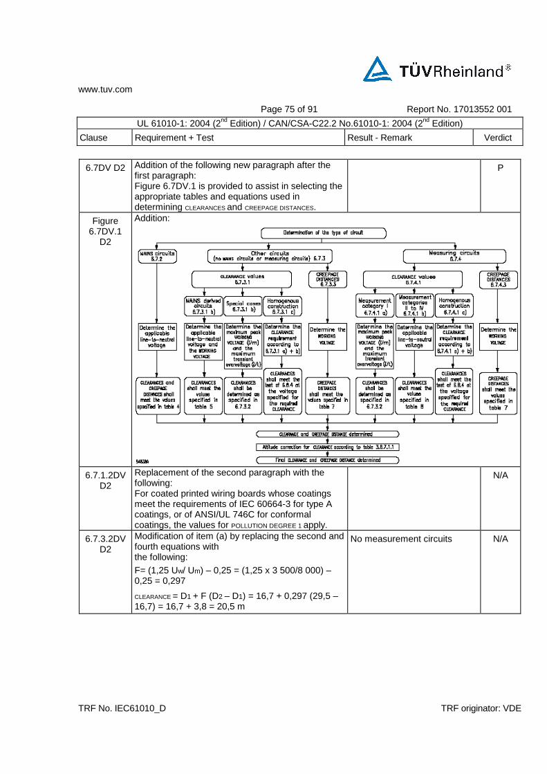
www.tuv.com
Page 75 of 91 Report No. 17013552 001
UL 61010-1: 2004 (2nd Edition) / CAN/CSA-C22.2 No.61010-1: 2004 (2nd Edition)
Clause Requirement + Test Result - Remark Verdict
TRF No. IEC61010_D TRF originator: VDE
6.7DV D2 Addition of the following new paragraph after the first paragraph: Figure 6.7DV.1 is provided to assist in selecting the appropriate tables and equations used in determining CLEARANCES and CREEPAGE DISTANCES.
P
Figure 6.7DV.1
D2
Addition:
6.7.1.2DV D2
Replacement of the second paragraph with the following: For coated printed wiring boards whose coatings meet the requirements of IEC 60664-3 for type A coatings, or of ANSI/UL 746C for conformal coatings, the values for POLLUTION DEGREE 1 apply.
N/A
6.7.3.2DV D2
Modification of item (a) by replacing the second and fourth equations with the following:
F= (1,25 Uw/ Um) – 0,25 = (1,25 x 3 500/8 000) – 0,25 = 0,297
CLEARANCE = D1 + F (D2 – D1) = 16,7 + 0,297 (29,5 – 16,7) = 16,7 + 3,8 = 20,5 m
No measurement circuits N/A
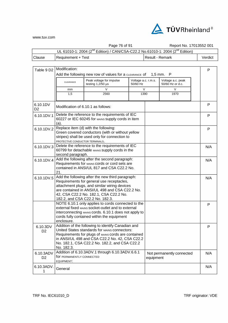
www.tuv.com
Page 76 of 91 Report No. 17013552 001
UL 61010-1: 2004 (2nd Edition) / CAN/CSA-C22.2 No.61010-1: 2004 (2nd Edition)
Clause Requirement + Test Result - Remark Verdict
TRF No. IEC61010_D TRF originator: VDE
Table 9 D2 Modification:
Add the following new row of values for a CLEARANCE of 1,5 mm. P
CLEARANCE Peak voltage for impulse testing 1,2/50 µs
Voltage a.c. r.m.s. 50/60 Hz
Voltage a.c. peak 50/60 Hz or d.c.
mm V V V
1,5 2560 1390 1970
P
6.10.1DV D2
Modification of 6.10.1 as follows: P
6.10.1DV.1 Delete the reference to the requirements of IEC 60227 or IEC 60245 for MAINS supply cords in item (a).
P
6.10.1DV.2 Replace item (d) with the following: Green covered conductors (with or without yellow stripes) shall be used only for connection to PROTECTIVE CONDUCTOR TERMINALS.
P
6.10.1DV.3 Delete the reference to the requirements of IEC 60799 for detachable MAINS supply cords in the second paragraph.
N/A
6.10.1DV.4 Add the following after the second paragraph: Requirements for MAINS cords or cord sets are contained in ANSI/UL 817 and CSA C22.2 No. 21.
N/A
6.10.1DV.5 Add the following after the new third paragraph: Requirements for general use receptacles, attachment plugs, and similar wiring devices are contained in ANSI/UL 498 and CSA C22.2 No. 42, CSA C22.2 No. 182.1, CSA C22.2 No. 182.2, and CSA C22.2 No. 182.3.
N/A
NOTE 6.10.1 only applies to cords connected to the external fixed MAINS socket-outlet and to external interconnecting MAINS cords. 6.10.1 does not apply to cords fully contained within the equipment enclosure.
P
6.10.3DV D2
Addition of the following to identify Canadian and United States standards for MAINS connectors: Requirements for plugs of MAINS cords are contained in ANSI/UL 498 and CSA C22.2 No. 42, CSA C22.2 No. 182.1, CSA C22.2 No. 182.2, and CSA C22.2 No. 182.3.
P
6.10.3ADV D2
Addition of 6.10.3ADV.1 through 6.10.3ADV.6.6.1 for PERMANENTLY CONNECTED
EQUIPMENT:
Not permanently connected equipment
N/A
6.10.3ADV.1
General N/A
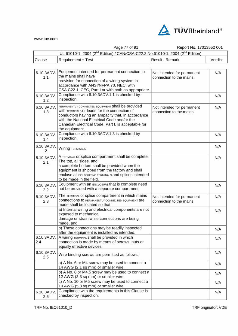
www.tuv.com
Page 77 of 91 Report No. 17013552 001
UL 61010-1: 2004 (2nd Edition) / CAN/CSA-C22.2 No.61010-1: 2004 (2nd Edition)
Clause Requirement + Test Result - Remark Verdict
TRF No. IEC61010_D TRF originator: VDE
6.10.3ADV.1.1
Equipment intended for permanent connection to the mains shall have provision for connection of a wiring system in accordance with ANSI/NFPA 70, NEC, with CSA C22.1, CEC, Part I or with both as appropriate.
Not intended for permanent connection to the mains
N/A
6.10.3ADV.1.2
Compliance with 6.10.3ADV.1.1 is checked by inspection.
N/A
6.10.3ADV.1.3
PERMANENTLY CONNECTED EQUIPMENT shall be provided with TERMINALS or leads for the connection of conductors having an ampacity that, in accordance with the National Electrical Code and/or the Canadian Electrical Code, Part I, is acceptable for the equipment.
Not intended for permanent connection to the mains
N/A
6.10.3ADV.1.4
Compliance with 6.10.3ADV.1.3 is checked by inspection.
N/A
6.10.3ADV.2
Wiring TERMINALS N/A
6.10.3ADV.2.1
A TERMINAL or splice compartment shall be complete. The top, all sides, and a complete bottom shall be provided when the equipment is shipped from the factory and shall enclose all FIELD WIRING TERMINALS and splices intended to be made in the field.
N/A
6.10.3ADV.2.2
Equipment with an ENCLOSURE that is complete need not be provided with a separate compartment.
N/A
6.10.3ADV.2.3
The TERMINAL or splice compartment in which mains connections to PERMANENTLY CONNECTED EQUIPMENT are made shall be located so that:
Not intended for permanent connection to the mains
N/A
a) Internal wiring and electrical components are not exposed to mechanical damage or strain while connections are being made, and
N/A
b) These connections may be readily inspected after the equipment is installed as intended.
N/A
6.10.3ADV.2.4
A wiring TERMINAL shall be provided in which connection is made by means of screws, nuts or equally effective devices.
N/A
6.10.3ADV.2.5
Wire binding screws are permitted as follows: N/A
a) A No. 6 or M4 screw may be used to connect a 14 AWG (2,1 sq mm) or smaller wire.
N/A
b) A No. 8 or M4.5 screw may be used to connect a 12 AWG (3,3 sq mm) or smaller wire.
N/A
c) A No. 10 or M5 screw may be used to connect a 10 AWG (5,3 sq mm) or smaller wire.
N/A
6.10.3ADV.2.6
Compliance with the requirements in this Clause is checked by inspection.
N/A
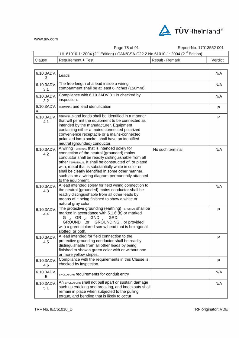
www.tuv.com
Page 78 of 91 Report No. 17013552 001
UL 61010-1: 2004 (2nd Edition) / CAN/CSA-C22.2 No.61010-1: 2004 (2nd Edition)
Clause Requirement + Test Result - Remark Verdict
TRF No. IEC61010_D TRF originator: VDE
6.10.3ADV.3
Leads N/A
6.10.3ADV.3.1
The free length of a lead inside a wiring compartment shall be at least 6 inches (150mm).
N/A
6.10.3ADV.3.2
Compliance with 6.10.3ADV.3.1 is checked by inspection.
N/A
6.10.3ADV.4
TERMINAL and lead identification P
6.10.3ADV.4.1
TERMINALS and leads shall be identified in a manner that will permit the equipment to be connected as intended by the manufacturer. Equipment containing either a mains-connected polarized convenience receptacle or a mains-connected polarized lamp socket shall have an identified neutral (grounded) conductor.
P
6.10.3ADV.4.2
A wiring TERMINAL that is intended solely for connection of the neutral (grounded) mains conductor shall be readily distinguishable from all other TERMINALS. It shall be constructed of, or plated with, metal that is substantially white in color or shall be clearly identified in some other manner, such as on a wiring diagram permanently attached to the equipment.
No such terminal N/A
6.10.3ADV.4.3
A lead intended solely for field wiring connection to the neutral (grounded) mains conductor shall be readily distinguishable from all other leads by means of it being finished to show a white or natural gray color.
N/A
6.10.3ADV.4.4
The protective grounding (earthing) TERMINAL shall be marked in accordance with 5.1.6 (b) or marked G,GR,GND,GRD, GROUND,or GROUNDING or provided with a green colored screw head that is hexagonal, slotted, or both.
P
6.10.3ADV.4.5
A lead intended for field connection to the protective grounding conductor shall be readily distinguishable from all other leads by being finished to show a green color with or without one or more yellow stripes.
P
6.10.3ADV.4.6
Compliance with the requirements in this Clause is checked by inspection.
P
6.10.3ADV.5
ENCLOSURE requirements for conduit entry N/A
6.10.3ADV.5.1
An ENCLOSURE shall not pull apart or sustain damage such as cracking and breaking, and knockouts shall remain in place when subjected to the pulling, torque, and bending that is likely to occur.
N/A

www.tuv.com
Page 79 of 91 Report No. 17013552 001
UL 61010-1: 2004 (2nd Edition) / CAN/CSA-C22.2 No.61010-1: 2004 (2nd Edition)
Clause Requirement + Test Result - Remark Verdict
TRF No. IEC61010_D TRF originator: VDE
6.10.3ADV.5.2
ENCLOSURES having sheet metal members with a thickness no less than 0,81 mm if of uncoated sheet steel, no less than 0,86 mm if of galvanized sheet steel, no less than 1,11 mm if of sheet aluminum, and no less than 1,09 mm if of sheet copper or sheet brass are not required to be tested in accordance with 6.10.3ADV.5.1.
N/A
6.10.3ADV.5.3
Compliance with the requirements in this Clause is checked by performing the tests of 6.10.3ADV.6.
N/A
6.10.3ADV.6
Conduit ENCLOSURE entry tests N/A
6.10.3ADV.6.1
General N/A
6.10.3ADV.6.1.1
After each of the tests in 6.10.3ADV.6.2 – 6.10.3ADV.6.5, the equipment shall meet the criteria defined in 6.10.3ADV.5.
N/A
NOTE Enclosures complying with ANSI/UL 50 are deemed to comply with 6.10.3ADV.6.2 and 6.10.3ADV.6.3.
N/A
6.10.3ADV.6.2
Conduit pull-out test N/A
6.10.3ADV.6.2.1
The ENCLOSURE shall be suspended by a length of rigid conduit installed in one wall of the ENCLOSURE or mounted as intended in service, and a pulling force of 200 lbs (890 N) shall be applied for 5 min to a length of conduit installed in the opposite wall (or wall with conduit entry if ENCLOSURE is mounted rather than suspended).
N/A
6.10.3ADV.6.3
Conduit torque test N/A
6.10.3ADV.6.3.1
The ENCLOSURE shall be securely mounted as intended in service. A torque in accordance with table 6.10.3ADV.6.3.1.1 shall be applied to a length of installed conduit in a direction tending to tighten the connection. The lever arm shall be measured from the center of the conduit.
N/A
Table 6.10.3ADV.
6.3.1.1
D2 Addition: Table 6.10.3ADV.6.3.1.1 – Tightening torque for conduit
Trade size of conduit, Tightening torque,
in lb-in (N•m)
3/4 and smaller (end-of-line ENCLOSURE) 200 (22,6)
3/4 and smaller 800 (90,4)
1, 1-1/4, 1-1/2 1000 (113)
2 and larger 1600 (181) NOTE An end-of-line ENCLOSURE is an ENCLOSURE that is intended to be connected at the end of a run of conduit and has only one 3/4-in maximum trade size opening for the connection of conduit.
N/A
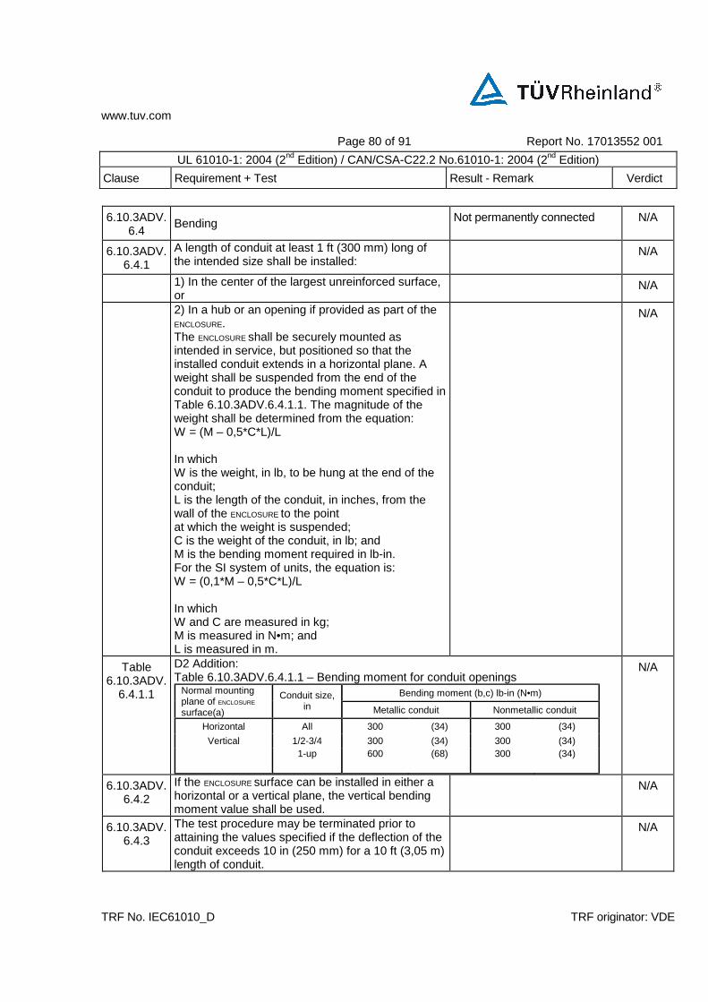
www.tuv.com
Page 80 of 91 Report No. 17013552 001
UL 61010-1: 2004 (2nd Edition) / CAN/CSA-C22.2 No.61010-1: 2004 (2nd Edition)
Clause Requirement + Test Result - Remark Verdict
TRF No. IEC61010_D TRF originator: VDE
6.10.3ADV.6.4
Bending Not permanently connected N/A
6.10.3ADV.6.4.1
A length of conduit at least 1 ft (300 mm) long of the intended size shall be installed:
N/A
1) In the center of the largest unreinforced surface, or
N/A
2) In a hub or an opening if provided as part of the ENCLOSURE. The ENCLOSURE shall be securely mounted as intended in service, but positioned so that the installed conduit extends in a horizontal plane. A weight shall be suspended from the end of the conduit to produce the bending moment specified in Table 6.10.3ADV.6.4.1.1. The magnitude of the weight shall be determined from the equation: W = (M – 0,5*C*L)/L In which W is the weight, in lb, to be hung at the end of the conduit; L is the length of the conduit, in inches, from the wall of the ENCLOSURE to the point at which the weight is suspended; C is the weight of the conduit, in lb; and M is the bending moment required in lb-in. For the SI system of units, the equation is: W = (0,1*M – 0,5*C*L)/L In which W and C are measured in kg; M is measured in N•m; and L is measured in m.
N/A
Table 6.10.3ADV.
6.4.1.1
D2 Addition: Table 6.10.3ADV.6.4.1.1 – Bending moment for conduit openings
Bending moment (b,c) lb-in (N•m) Normal mounting plane of ENCLOSURE
surface(a)
Conduit size, in Metallic conduit Nonmetallic conduit
Horizontal All 300 (34) 300 (34)
Vertical 1/2-3/4 300 (34) 300 (34)
1-up 600 (68) 300 (34)
N/A
6.10.3ADV.6.4.2
If the ENCLOSURE surface can be installed in either a horizontal or a vertical plane, the vertical bending moment value shall be used.
N/A
6.10.3ADV.6.4.3
The test procedure may be terminated prior to attaining the values specified if the deflection of the conduit exceeds 10 in (250 mm) for a 10 ft (3,05 m) length of conduit.
N/A

www.tuv.com
Page 81 of 91 Report No. 17013552 001
UL 61010-1: 2004 (2nd Edition) / CAN/CSA-C22.2 No.61010-1: 2004 (2nd Edition)
Clause Requirement + Test Result - Remark Verdict
TRF No. IEC61010_D TRF originator: VDE
6.10.3ADV.6.4.4
For an end-of-line ENCLOSURE as defined in the note of Table6.10.3ADV.6.3.1.1, the bending moment shall be 150 lb-in (17,0 N•m).
N/A
6.10.3ADV.6.5
Knockouts N/A
6.10.3ADV.6.5.1
A knockout shall be subjected to a force of 20 lb (89 N) applied at right angles by means of a mandrel with a 1/4-in (6,4-mm) diameter flat end. The mandrel shall be applied at the point most likely to cause movement of the knockout.
N/A
6.10.3ADV.6.6
Continuity of bonding P
6.10.3ADV.6.6.1
An enclosure made of insulating material, either wholly or in part, shall have an acceptable bonding means to provide continuity of bonding between all metallic conduits entering the enclosure.
P
6.11DV D2 Modification of the title: Add and maintaining polarity to the end of the Clause title.
N/A
6.11.3ADV Addition of requirement for polarity of connections: Any line-connected single-pole switch, any center contact of a lampholder, and any automatic control with a marked off position shall be connected to a TERMINAL or lead intended for connection to the ungrounded conductor of the supply circuit.
N/A
8DV D2 Modification of the title: Add and resistance to UV radiation to the end of the Clause title.
N/A
8.2ADV D2 Addition of nonmetallic enclosure requirement: Nonmetallic enclosures intended for outdoor use shall meet the UV resistance requirements of ANSI/UL 746C or of C22.2 No. 0.17, or of both as appropriate. NOTE ANSI/UL 746, clause 27, requires a 1000 hour UV/water exposure preconditioning using a xenon-arc or alternatively, a 720 hour UV/water exposure preconditioning using twin carbon-arcs. CSA C22.2 No. 0.17, clause 5.9, only permits the 1000 hour UV/water exposure preconditioning.
Not intended for outdoor use N/A
9.2.1DV D2 Addition of the following to the end of item (a): Flame RATINGS of ANSI/UL 94 V-0, V-1, and V-2 are equivalent to the flammability classifications of IEC 60707 FV-0, FV-1, and FV-2, respectively.
Protection via methods 9 a) and b)
N/A
NOTE Flame ratings FT-1 of CSA C22.2 No. 0.3 and VW-1 ANSI/UL 1581 are considered acceptable for insulated wire and cable.
N/A
9.5ADV D2 Addition of the following for connections to overcurrent protective devices:
P
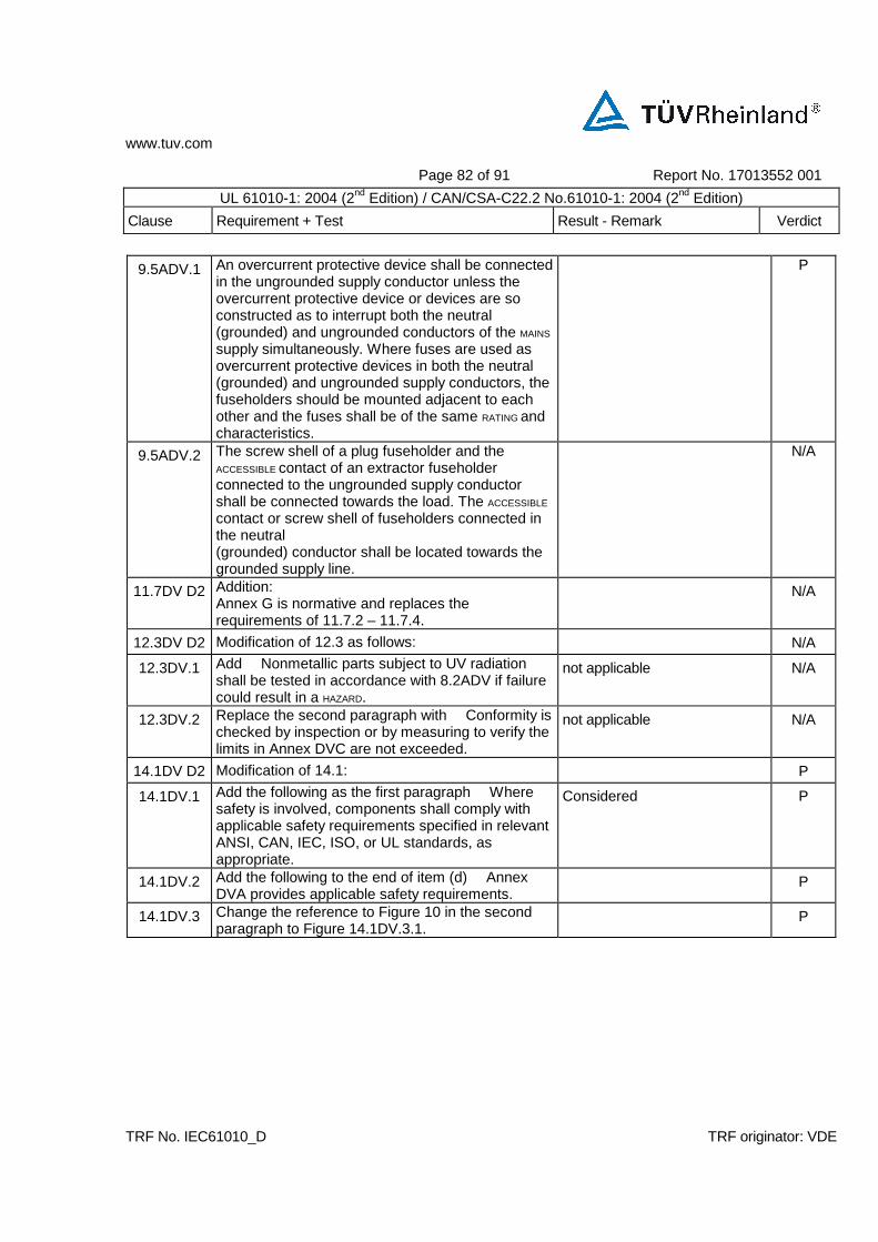
www.tuv.com
Page 82 of 91 Report No. 17013552 001
UL 61010-1: 2004 (2nd Edition) / CAN/CSA-C22.2 No.61010-1: 2004 (2nd Edition)
Clause Requirement + Test Result - Remark Verdict
TRF No. IEC61010_D TRF originator: VDE
9.5ADV.1 An overcurrent protective device shall be connected in the ungrounded supply conductor unless the overcurrent protective device or devices are so constructed as to interrupt both the neutral (grounded) and ungrounded conductors of the MAINS
supply simultaneously. Where fuses are used as overcurrent protective devices in both the neutral (grounded) and ungrounded supply conductors, the fuseholders should be mounted adjacent to each other and the fuses shall be of the same RATING and characteristics.
P
9.5ADV.2 The screw shell of a plug fuseholder and the ACCESSIBLE contact of an extractor fuseholder connected to the ungrounded supply conductor shall be connected towards the load. The ACCESSIBLE
contact or screw shell of fuseholders connected in the neutral (grounded) conductor shall be located towards the grounded supply line.
N/A
11.7DV D2 Addition: Annex G is normative and replaces the requirements of 11.7.2 – 11.7.4.
N/A
12.3DV D2 Modification of 12.3 as follows: N/A
12.3DV.1 Add Nonmetallic parts subject to UV radiation shall be tested in accordance with 8.2ADV if failure could result in a HAZARD.
not applicable N/A
12.3DV.2 Replace the second paragraph with Conformity is checked by inspection or by measuring to verify the limits in Annex DVC are not exceeded.
not applicable N/A
14.1DV D2 Modification of 14.1: P
14.1DV.1 Add the following as the first paragraph Where safety is involved, components shall comply with applicable safety requirements specified in relevant ANSI, CAN, IEC, ISO, or UL standards, as appropriate.
Considered P
14.1DV.2 Add the following to the end of item (d) Annex DVA provides applicable safety requirements.
P
14.1DV.3 Change the reference to Figure 10 in the second paragraph to Figure 14.1DV.3.1.
P

www.tuv.com
Page 83 of 91 Report No. 17013552 001
UL 61010-1: 2004 (2nd Edition) / CAN/CSA-C22.2 No.61010-1: 2004 (2nd Edition)
Clause Requirement + Test Result - Remark Verdict
TRF No. IEC61010_D TRF originator: VDE
Figure 14.1DV.3.1
DE
Addition:
P
14.8DV D2 Addition of the following to the end of the first paragraph: Flame RATINGS of ANSI/UL 94 and CAN/CSA C22.2 No. 0.17, V-0, V-1, and V-2, are equivalent to the flammability classifications of IEC 60707 FV-0, FV-1, and FV-2, respectively.
P
14.9ADV D2
Addition of 14.9ADV.1 through 14.9ADV.2.2 for Electromagnetic Compatibility (EMC) materials:
N/A
14.9ADV.1 Conductive coatings No such coating N/A
14.9ADV.1.1
The bond of a conductive (metallic) coating applied to a polymeric part shall be evaluated.
N/A
14.9ADV.1.2
Compliance with the requirements in 14.9ADV.1 is checked by:
N/A
a) Evaluating the bond in accordance with the requirements for Adhesives in ANSI/UL 746C and/or CSA C22.2 No. 0.17, or
N/A
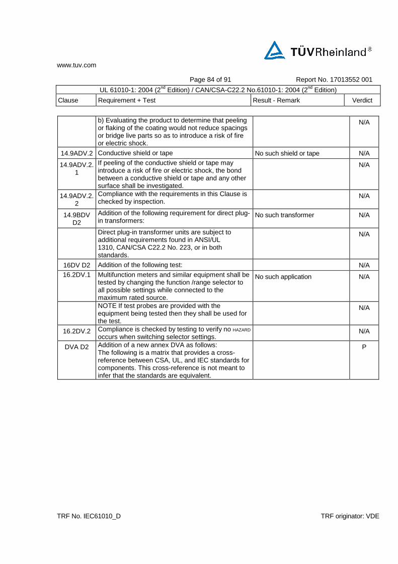
www.tuv.com
Page 84 of 91 Report No. 17013552 001
UL 61010-1: 2004 (2nd Edition) / CAN/CSA-C22.2 No.61010-1: 2004 (2nd Edition)
Clause Requirement + Test Result - Remark Verdict
TRF No. IEC61010_D TRF originator: VDE
b) Evaluating the product to determine that peeling or flaking of the coating would not reduce spacings or bridge live parts so as to introduce a risk of fire or electric shock.
N/A
14.9ADV.2 Conductive shield or tape No such shield or tape N/A
14.9ADV.2.1
If peeling of the conductive shield or tape may introduce a risk of fire or electric shock, the bond between a conductive shield or tape and any other surface shall be investigated.
N/A
14.9ADV.2.2
Compliance with the requirements in this Clause is checked by inspection.
N/A
14.9BDV D2
Addition of the following requirement for direct plug-in transformers:
No such transformer N/A
Direct plug-in transformer units are subject to additional requirements found in ANSI/UL 1310, CAN/CSA C22.2 No. 223, or in both standards.
N/A
16DV D2 Addition of the following test: N/A 16.2DV.1 Multifunction meters and similar equipment shall be
tested by changing the function /range selector to all possible settings while connected to the maximum rated source.
No such application N/A
NOTE If test probes are provided with the equipment being tested then they shall be used for the test.
N/A
16.2DV.2 Compliance is checked by testing to verify no HAZARD
occurs when switching selector settings. N/A
DVA D2 Addition of a new annex DVA as follows: The following is a matrix that provides a cross-reference between CSA, UL, and IEC standards for components. This cross-reference is not meant to infer that the standards are equivalent.
P
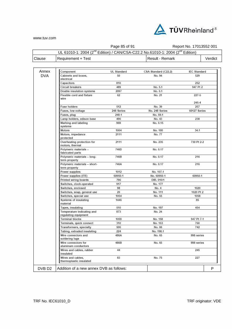
www.tuv.com
Page 85 of 91 Report No. 17013552 001
UL 61010-1: 2004 (2nd Edition) / CAN/CSA-C22.2 No.61010-1: 2004 (2nd Edition)
Clause Requirement + Test Result - Remark Verdict
TRF No. IEC61010_D TRF originator: VDE
Annex DVA
DVB D2 Addition of a new annex DVB as follows: P
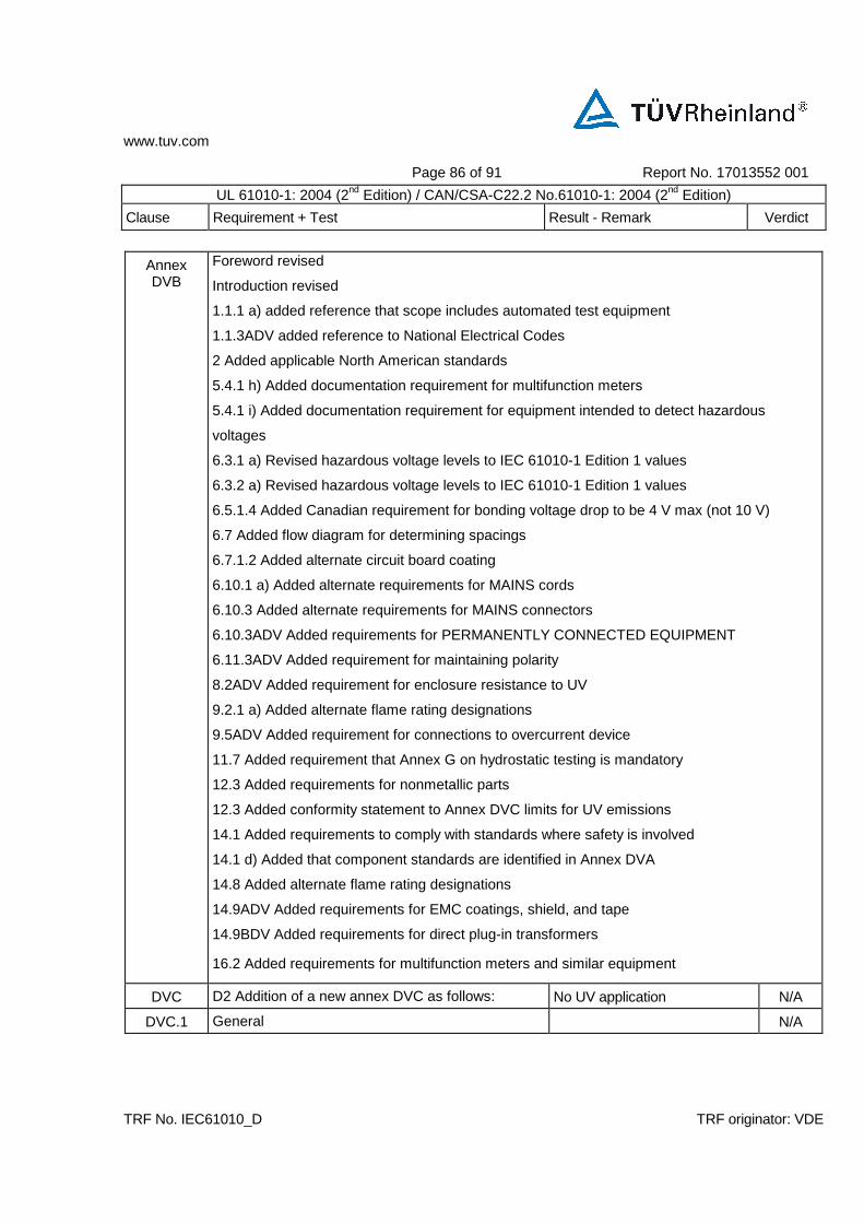
www.tuv.com
Page 86 of 91 Report No. 17013552 001
UL 61010-1: 2004 (2nd Edition) / CAN/CSA-C22.2 No.61010-1: 2004 (2nd Edition)
Clause Requirement + Test Result - Remark Verdict
TRF No. IEC61010_D TRF originator: VDE
Annex DVB
Foreword revised
Introduction revised
1.1.1 a) added reference that scope includes automated test equipment
1.1.3ADV added reference to National Electrical Codes
2 Added applicable North American standards
5.4.1 h) Added documentation requirement for multifunction meters
5.4.1 i) Added documentation requirement for equipment intended to detect hazardous
voltages
6.3.1 a) Revised hazardous voltage levels to IEC 61010-1 Edition 1 values
6.3.2 a) Revised hazardous voltage levels to IEC 61010-1 Edition 1 values
6.5.1.4 Added Canadian requirement for bonding voltage drop to be 4 V max (not 10 V)
6.7 Added flow diagram for determining spacings
6.7.1.2 Added alternate circuit board coating
6.10.1 a) Added alternate requirements for MAINS cords
6.10.3 Added alternate requirements for MAINS connectors
6.10.3ADV Added requirements for PERMANENTLY CONNECTED EQUIPMENT
6.11.3ADV Added requirement for maintaining polarity
8.2ADV Added requirement for enclosure resistance to UV
9.2.1 a) Added alternate flame rating designations
9.5ADV Added requirement for connections to overcurrent device
11.7 Added requirement that Annex G on hydrostatic testing is mandatory
12.3 Added requirements for nonmetallic parts
12.3 Added conformity statement to Annex DVC limits for UV emissions
14.1 Added requirements to comply with standards where safety is involved
14.1 d) Added that component standards are identified in Annex DVA
14.8 Added alternate flame rating designations
14.9ADV Added requirements for EMC coatings, shield, and tape
14.9BDV Added requirements for direct plug-in transformers
16.2 Added requirements for multifunction meters and similar equipment
DVC D2 Addition of a new annex DVC as follows: No UV application N/A
DVC.1 General N/A

www.tuv.com
Page 87 of 91 Report No. 17013552 001
UL 61010-1: 2004 (2nd Edition) / CAN/CSA-C22.2 No.61010-1: 2004 (2nd Edition)
Clause Requirement + Test Result - Remark Verdict
TRF No. IEC61010_D TRF originator: VDE
DVC.1.1 These threshold limit values (TLVs) refer to ultraviolet (UV) radiation in the spectral region between 180 and 400 nm and represent conditions under which it is believed that nearly all workers may be repeatedly exposed without adverse health effects. These values for exposure of the eye or the skin apply to UV radiation from arc, gas, and vapor discharges, fluorescent and incandescent sources, and solar radiation, but they do not apply to UV lasers (see the TLVs for lasers). These values do not apply to UV radiation exposure of photosensitive individuals or of individuals concomitantly exposed to photosensitizing agents. These exposures to the eye do not apply to aphakics. (See light and near-infrared radiation TLVs). These values should be used as guides in the control of exposure to continuous sources where the exposure durations shall not be less than 0.1 sec.
N/A
DVC.1.2 These values should be used as guides in the control of exposure to UV sources and should not be regarded as a fine line between safe and dangerous levels.
N/A
DVC.2 Recommended values N/A
DVC.2.1 The TLVs for occupational exposure to UV radiation incident upon skin or eye where irradiance values are known and exposure time is controlled are as follows:
N/A
a) For the near UV spectral region (320 to 400 nm), total irradiance incident upon the unprotected eye should not exceed 1.0 W/cm2 for periods greater than 103 seconds (approximately 16 minutes) and for exposure times less than 103 seconds should not exceed 1.0 J/cm2.
N/A
b) The UV radiant exposure incident upon the unprotected skin or eye should not exceed the values given in Table DVC.4.1 or Figure DVC.4.1 within an 8 hour period.
N/A

www.tuv.com
Page 88 of 91 Report No. 17013552 001
UL 61010-1: 2004 (2nd Edition) / CAN/CSA-C22.2 No.61010-1: 2004 (2nd Edition)
Clause Requirement + Test Result - Remark Verdict
TRF No. IEC61010_D TRF originator: VDE
c) To determine the effective irradiance of a broad band source weighted against the peak of the spectral effectiveness curve (270 nm), the following weighting formula should be used: Eeff = E S In which Eeff is the effective irradiance relative to a monochromatic source at 270 nm in W/cm2
[J/(s•cm2)]; E is the spectral irradiance in W/(cm2•nm); S is the relative spectral effectiveness (unitless);
is the band width in nm.
N/A
d) For most white-light sources and all open arcs, the weighting of spectral irradiance between 200 and 315 nm should suffice to determine the effective irradiance. Only specialized UV sources designed to emit UV-A radiation would normally require spectral weighting from 315 to 400 nm.
N/A
e) Permissible exposure time in seconds for exposure to actinic UV radiation incident upon the unprotected skin or eye may be computed by dividing 0.003 J/cm2 by Eeff in W/cm2. The exposure time may also be determined using Table DVC.4.2 which provides exposure times corresponding to effective irradiances in µW/cm2.
N/A
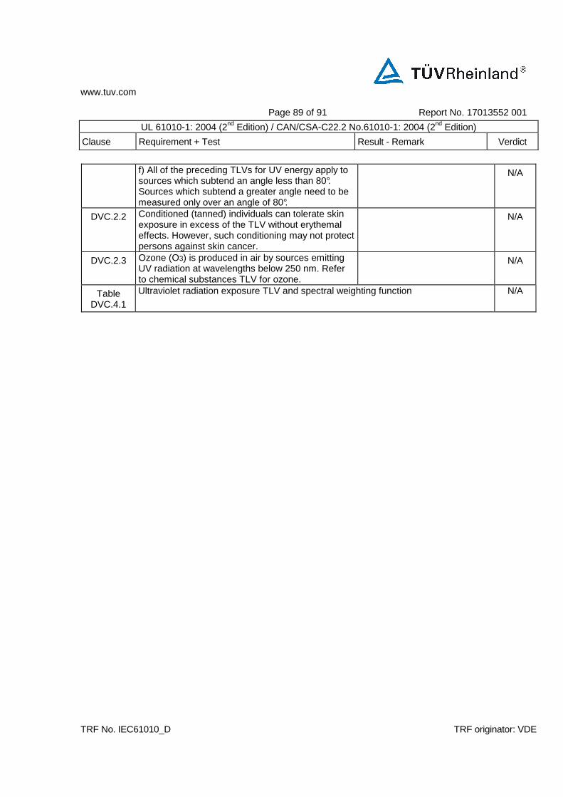
www.tuv.com
Page 89 of 91 Report No. 17013552 001
UL 61010-1: 2004 (2nd Edition) / CAN/CSA-C22.2 No.61010-1: 2004 (2nd Edition)
Clause Requirement + Test Result - Remark Verdict
TRF No. IEC61010_D TRF originator: VDE
f) All of the preceding TLVs for UV energy apply to sources which subtend an angle less than 80°. Sources which subtend a greater angle need to be measured only over an angle of 80°.
N/A
DVC.2.2 Conditioned (tanned) individuals can tolerate skin exposure in excess of the TLV without erythemal effects. However, such conditioning may not protect persons against skin cancer.
N/A
DVC.2.3 Ozone (O3) is produced in air by sources emitting UV radiation at wavelengths below 250 nm. Refer to chemical substances TLV for ozone.
N/A
Table DVC.4.1
Ultraviolet radiation exposure TLV and spectral weighting function N/A
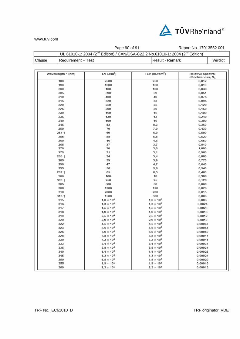
www.tuv.com
Page 90 of 91 Report No. 17013552 001
UL 61010-1: 2004 (2nd Edition) / CAN/CSA-C22.2 No.61010-1: 2004 (2nd Edition)
Clause Requirement + Test Result - Remark Verdict
TRF No. IEC61010_D TRF originator: VDE
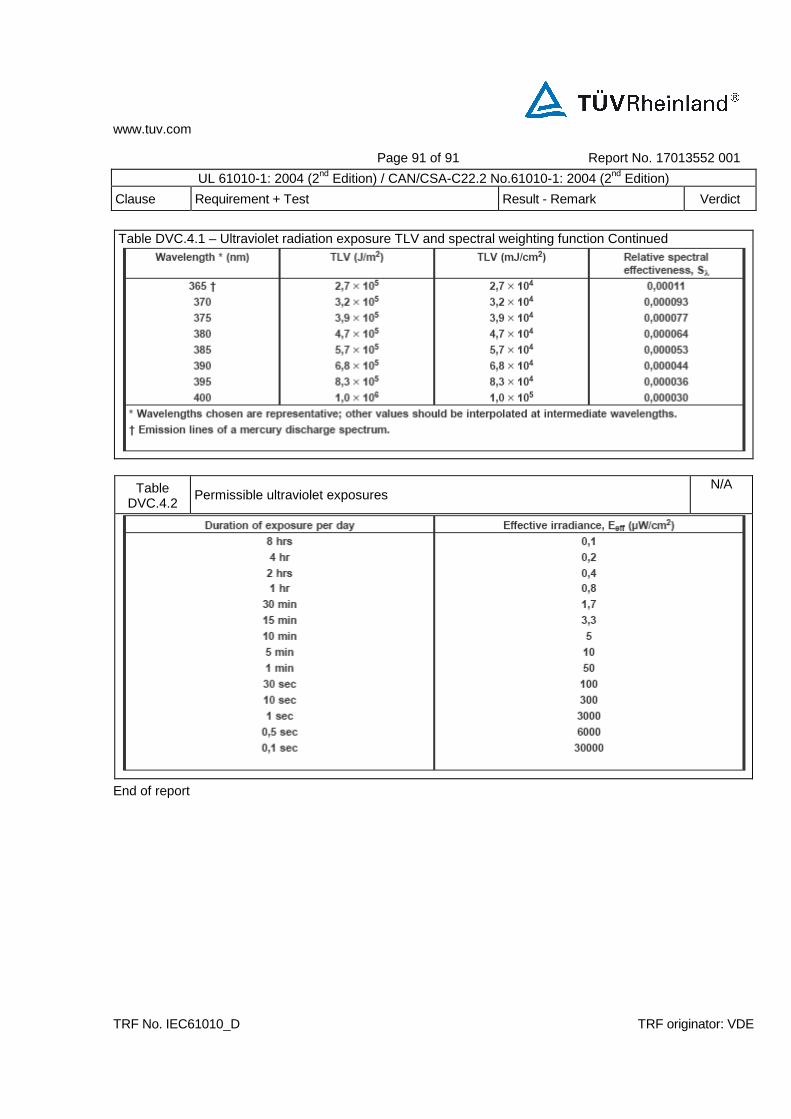
www.tuv.com
Page 91 of 91 Report No. 17013552 001
UL 61010-1: 2004 (2nd Edition) / CAN/CSA-C22.2 No.61010-1: 2004 (2nd Edition)
Clause Requirement + Test Result - Remark Verdict
TRF No. IEC61010_D TRF originator: VDE
Table DVC.4.1 – Ultraviolet radiation exposure TLV and spectral weighting function Continued
Table DVC.4.2
Permissible ultraviolet exposures N/A
End of report