test plan for the evaluation of in situ thermal … · ineel/ext-03-00059 revision 0 project no....
TRANSCRIPT
I NEEL/EXT-03-00059 Revision 0
Project No. 23378
Test Plan for the Evaluation of In Situ Thermal Desorption and Grouting Technologies for Operable Unit 7-13/74
Neal A. Yancey Peter G. Shaw David F. Nickelson Gretchen E. Matthern Guy G. Loomis
October 2003
Idaho National Engineering and Environmental Laboratory Bechtel BWXT Idaho. LLC
INEEL/EXT-03-00059 Revision 0
Project No. 23378
Test Plan for the Evaluation of In Situ Thermal Desorption and Grouting Technologies for
Operable Unit 7-13/14
Neal A. Yancey Peter G. Shaw
David F. Nickelson Gretchen E. Matthern
Guy G. Loomis
October 2003
Idaho Completion Project Idaho Falls, Idaho 83415
Prepared for the U.S. Department of Energy
Assistant Secretary for Environmental Management Under DOE Idaho Operations Office
Contract DE-AC07-991D13727

ABSTRACT
This test plan provides the technical aspects and procedures required for conducting a Comprehensive Environmental Response, Compensation, and Liability Act preremedial design investigation for Waste Area Group 7, Operable Unit 7-13/14. The test plan supports the evaluation of in situ thermal desorption, in situ grouting, and ex situ grouting as technologies applicable to wastes buried at the Operable Unit 7-13/14.
Data from these tests will be used to support the Operable Unit 7-13/14 Remedial Investigation/Feasibility Study and ultimately the Operable Unit 7-13/14 Record of Decision. In situ thermal desorption will be evaluated for buried Rocky Flats Plant transuranic wastes. In situ grouting will be evaluated for application on buried transuranic and nontransuranic wastes. Ex situ grouting will be evaluated for Pad A waste. Testing will be performed with cold (nonradioactive) surrogates, hot (radioactive) surrogates, and actual waste (as appropriate and available). The tests will be conducted at laboratory scale.
... 111

CONTENTS ...
ABSTRACT ........................................................................................................................................... iii
ACRONYMS ......................................................................................................................................... xi
1 . INTRODUCTION ......................................................................................................................... 1
. . 1.1 Description of the Wastes .................................................................................................... 1
1.2 Contaminants of Concern .................................................................................................... 3
2 . SCOPE .......................................................................................................................................... 4
2.1 Application of In Situ Thermal Desorption .......................................................................... 4
2.2 Application of In Situ Grouting ........................................................................................... 7
2.3 Application of Ex Situ Grouting .......................................................................................... 9
2.4 Past Work ............................................................................................................................ 9
2.5 Purpose ............................................................................................................................. 10
. . 2.6 Test Objectives .................................................................................................................. 10
2.6. I
2.6.2 2.6.3 2.6.4 2.6.5 2.6.6
2.6.7 2.6.8
Develop Data to Support Contaminant Transport Modeling for Treated Waste Forms 11 Evaluate Dur .................................................................... 12 Evaluate the Release of Radionuclide Particulate During Grouting ......................... 13 Evaluate WaxfixB for Use as a Grout ..................................................................... 13 Quantify Major Emissions as Wastes and Soils are Slowly Heated .......................... 15 Determine the Degree of Hazardous Organic Contaminant and Nitrate Removal and/or Destruction from Soil and Waste 15 Test Potential Mixtures of Organics and Nitrates for Reactivity .............................. 16 Data Use and Priority for Required Tests ................................................................ 17
3 . ORGANIZATION AND RESPONSIBILITIES ........................................................................... 25
. . . . 3.1 Responsibilities ................................................................................................................. 25
. . 3.2 Training ............................................................................................................................ 26
4 . TEST DESCRIPTION ................................................................................................................. 27
4.1 SDA Targeted Waste Types ............................................................................................... 27
4.1.1 TRU Pits and Trenches ........................................................................................... 27 4.1.2 Non-TRU Pits and Trenches, and Soil Vault Rows Waste Surrogate ....................... 33 4.1.3 Pad A Waste .......................................................................................................... 33
V

4.2 In Situ Thermal Desorption ............................................................................................... 34
4.2.1 Testing Overview ................................................................................................... 34 4.2.2 General Test Procedures ......................................................................................... 35 4.2.3 Required Test-Compositional Analysis ................................................................ 36 4.2.4 Required Test-Reactivity ..................................................................................... 36 4.2.5 Required Tests-Nitrate and Organic Decomposition and Off-Gas 40 4.2.6 Required Test-Leachability 44
4.3 In Situ Grouting ................................................................................................................. 48
4.3.1 In Situ Grouting Testing Overview ......................................................................... 50 4.3.2 General Test Procedures ......................................................................................... 50 4.3.3 ISG of TRU Pits and Trenches Waste ..................................................................... 51 4.3.4 ISG of ISTD Treated TRU Waste Matri 60 4.3.5 ISG of non-TRU Pits and Trenches and 63
4.4 Ex Situ Grouting ............................................................................................................... 66
4.4.1 Required Test-Compositional Analysis of Pad A Waste ....................................... 67 4.4.2 Required Test-Leaching ....................................................................................... 67
4.5 Required Equipment. Materials. and Facilities for ISTD. ISG. and ESG Tests .................... 69
4.5.1 Equipment for ISTD, ISG. and ESG Tests 69 4.5.2 Materials ................................................................................................................ 69 4.5.3 Laboratory Facilities .............................................................................................. 71 4.5.4 Laboratory Reactivity and Off-Gas Measurements .................................................. 71
. . .
4.6 Contingency ...................................................................................................................... 72
5 . IMPLEMENTING PROCEDURES ............................................................................................. 73
5.1 Management and Technical Procedures ............................................................................. 73
5.2 Sample and Analysis Management .................................................................................... 73
5.3 Procedures Not Applicable ................................................................................................ 75
5.4 Procedure Modifications .................................................................................................... 75
6 . SEQUENCE OF ACTIVITIES .................................................................................................... 76
7 . QUALITY ASSURANCE ........................................................................................................... 77
. . 7.1 Data Quality Objectives ..................................................................................................... 77
7.2 Analytical Data Categories ................................................................................................ 77
7.3 Test Plan Modification ...................................................................................................... 78
8 . HEALTH AND SAFETY ............................................................................................................ 79
vi
9 . WASTE MANAGEMENT .......................................................................................................... 80
9.1 Testing Wastes .................................................................................................................. 80
9.2 Waste Minimization and Pollution Prevention ................................................................... 80
9.3 Handling. Storage. and Disposition .................................................................................... 80
10 . DATA ANALYSIS AND INTERPRETATION .......................................................................... 81
10.1 Data Reduction for All Tests ............................................................................................. 81
10.2 Data Validation for All Tests ............................................................................................. 81
10.3 Procedures for Assessing Data ........................................................................................... 82
10.3.1 Notation ................................................................................................................. 82 10.3.2 Estimation of the Variance of the Measurement Process ......................................... 82
10.4 Sample Shipping and Data Reporting ................................................................................ 83
10.4.1 Sample Containers and Container Labels .................................... 10.4.2 Sample Numbering Scheme ....................................................... 10.4.3 Laboratory Logbooks ....... .......................................................... 10.4.4 Sample Custody .................................. 10.4.5 Chain of Custody Record ....................................... 10.4.6 Reporting of Analytical Results ..............................
................................................ 84 ............................ 84 ............................ 84
10.5 Data Evaluation and Analysis ............................................................................................ 84
85 85
10.5.1 Spikes .............................. .......................................................... 10.5.2 Blanks .............................. .......................................................... 10.5.3 Replicates ........................................... ................................................ 85
10.6 Data Interpretation ............................................................................................................. 86
. . . . 10.6.1 Actinide Leachablllty ............................................................................................. 86 10.6.2 Nitrate and Organic Chloride Decomposition ......................................................... 87
10.7 Data Collection Techniques ............................................................................................... 87
10.8 Document Management and Sample Handling ................................................................... 87
10.8.1 Data ....................................................................................................................... 87 10.8.2 Test Plan, Documents, and Logbooks ..................................................................... 88
11 . REFERENCES ............................................................................................................................ 90
Appendix A-List of Equipment for ISTD. ISG/ESG ............................................................................ 95
Appendix B-Expected Composition of Waste Samples from Pit 9 ..................................................... 101
vii
1.
2.
3.
4.
5.
6.
7.
8.
9.
1.
2.
3.
4.
5.
6.
7.
8.
9.
10.
11.
12.
13.
14.
15.
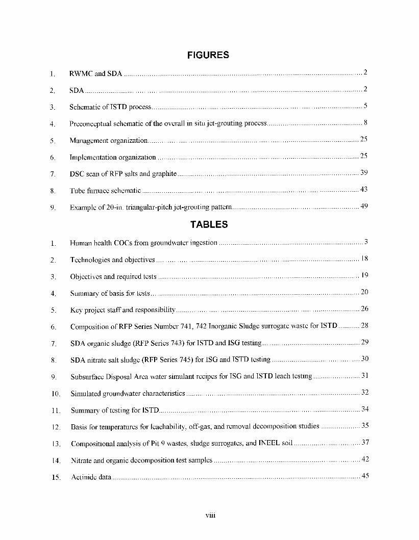
FIGURES
RWMC and SDA .......................................................................................................................... 2
..... 2 ................................................. ................................................
Schematic of ISTD process ................................................. ...................................... 5
Preconceptual schematic of the overall in situ j et-grouting process.. ..........................................
... 25
.................... 25
.................................................... 39
... 43
.................... 49
Management organization.. ..................... ................................................
Implementation organization . . .................................................
DSC scan of W P salts and graphite .........................
Tube hrnace schematic .......................... ................................................
Example of 20-in. triangular-pitch jet-grouting pattern.. ...........................
TABLES
Human health COCs from groundwater ingestion ....................
Technologies and objectives ....................................
Objectives and required tests ..................
Summary of basis for tests.. ....
Key project staff and responsibility.. ........................
...................................... 3
.................................................... 18
... 19
.................... 20
.................................................... 26
................................................
.................................................
Composition of W P Series Number 74 1, 742 Inorganic Sludge surrogate waste for ISTD
.................... 29 SDA organic sludge ( W P Series 743) for ISTD and ISG testing ..............
SDA nitrate salt sludge ( W P Series 745) for ISG and ISTD testing ............................................. 30
Subsurface Disposal Area water simulant recipes for ISG and ISTD leach testing.. ..
Simulated groundwater characteristics ................................................. .................... 32
Summary of testing for ISTD.. .................................................
Basis for temperatures for leachability, off-gas, and removal decomposition studies
Compositional analysis of Pit 9 wastes, sludge surrogates, and INEEL soil
Nitrate and organic decomposition test samples .......................
... 31
.................................... 34
... 35
.................... 37
.................................... 42
... 45 Actinide data .......................................... ................................................
Vl l l
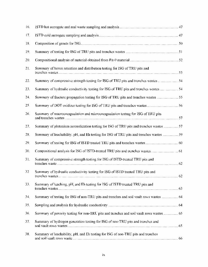
16 . ISTD hot surrogate and real waste sampling and analysis ............................................................. 47
17 .
18 .
19 .
20 .
21 .
22 .
23 .
24 .
25 .
26 .
27 .
28 .
29 .
30 .
31 .
32 .
33 .
34 .
35 .
36 .
37 .
38 .
ISTD cold surrogate sampling and analysis .................................................................................. 47
. . Composition of grouts for ISG ..................................................................................................... 50
Summary of testing for ISG of TRU pits and trenches wastes ...................................................... 51
Compositional analysis of material obtained from Pit-9 material .................................................. 52
Summary of boron retention and distribution testing for ISG of TRU pits and trenches wastes ............................................................................................................................ 53
Summary of compressive strength testing for ISG of TRU pits and trenches wastes ..................... 54
Summary of hydraulic conductivity testing for ISG of TRU pits and trenches wastes ................... 54
Summary of fracture propagation testing for ISG of TRU pits and trenches wastes ...................... 55
Summary of DOT oxidizer testing for ISG of TRU pits and trenches wastes ................................ 56
Summary of macroencapsulation and microencapsulation testing for ISG of TRU pits and trenches wastes ..................................................................................................................... 57
Summary of plutonium aerosolization testing for ISG of TRU pits and trenches wastes ............... 57
Summary of leachability. pH. and Eh testing for ISG of TRU pits and trenches wastes ................ 59
Summary of testing for ISG of ISTD treated TRU pits and trenches wastes .................................. 60
Compositional analysis for ISG of ISTD-treated TRU pits and trenches wastes ............................ 61
Summary of compressive strength testing for ISG of ISTD-treated TRU pits and trenches waste ............................................................................................................................. 62
Summary of hydraulic conductivity testing for ISG of ISTD treated TRU pits and trenches wastes ............................................................................................................................ 62
Summary of leaching. pH. and Eh testing for ISG of ISTD treated TRU pits and trenches wastes ............................................................................................................................ 63
Summary of testing for ISG of non-TRU pits and trenches and soil vault rows wastes ................. 64
Sampling and analysis for hydraulic conductivity ........................................................................ 64
Summary of porosity testing for non-TRU pits and trenches and soil vault rows wastes ............... 65
Summary of hydrogen generation testing for ISG of non-TRU pits and trenches and soil vault rows wastes .................................................................................................................. 65
Summary of leachability. pH. and Eh testing for ISG of non-TRU pits and trenches and soil vault rows waste ............................................................................................................. 66
ix
39. Composition of solidification agents for Pad A salt solidification.. ..................................
40. Compositional analysis of Pad A waste.. .. ...........................................
41. Sampling and analysis for leaching of real waste ................. ......................................... 68
68
............. 74
42. Technologies and required tests ............................. ...........................................
Sampling and Analysis Management Program implementing procedures .......... 43.
44. Preliminary sequence of tests and activities ........................................ ........................... 76
X
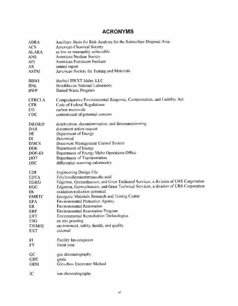
ACRONYMS
A B M ACS ALARA ANS API AR ASTM
BBWI BNL BWP
CERCLA CFR co COC
D&D&D DAR DE DI DMCS DOE
DOT DSC
DOE-ID
EDF EDTA EG&G EGG Eh EMRTC EPA ER ERP ERT ESG ESH&Q EXT
FI FY
GC GDE GEM
IC
Ancillary Basis for f i sk Analysis for the Subsurface Disposal Area American Chemical Society as low as reasonably achievable American Nuclear Society American Petroleum Institute annual report American Society for Testing and Materials
Bechtel BWXT Idaho, LLC Brookhaven National Laboratory Buried Waste Program
Comprehensive Environmental Response, Compensation, and Liability Act Code of Federal Regulations carbon monoxide contaminant of potential concern
deactivation, decontamination, and decommissioning document action request Department of Energy Deionized Document Management Control System Department of Energy Department of Energy Idaho Operations Office Department of Transportation differential scanning calorimetry
Engineering Design File Ethylenediaminetetraacedic acid Edgerton, Germeshausen, and Grier Technical Services, a division of URS Corporation Edgerton, Germeshausen, and Grier Technical Services, a division of URS Corporation oxidation-reduction potential Energetic Materials Research and Testing Center Environmental Protection Agency Environmental Restoration Environmental Restoration Program Environmental Remediation Technologies ex situ grouting environment, safety, health, and quality external
Facility Investigation fiscal year
gas chromatography guide Glovebox Excavator Method
ion chromatography
x1

ICP-MS IDEQ IHR INEEL INEL INTEC IRC ISG ISTD ITRP
LLC
MCP
NA NRC
ou PCE
PLN PH
QAMS
Redox RFO RFP RI/F S RPD RWMC
SA SAP SDA SMO sow SR SSR STD STP SVOA sw TBD TC TCA TCE TCLP TOC
inductively coupled plasma-mass spectrometry Idaho Department of Environmental Quality Industrial Hazards Review Idaho National Engineering and Environmental Laboratory Idaho National Engineering Laboratory (predecessor of the INEEL) Idaho Nuclear Technology and Engineering Center INEEL Research Center in situ grouting (defined as in situ jet grouting for purposes of this test plan) in situ thermal desorption Independent Technical Review Panel
Limited Liability Company
Management Control Procedure
not applicable Nuclear Regulatory Commission
Operable Unit
tetrachloroethylene acid-base character plan
quality assurance management staff
oxidatiodreduction potential Rocky Flats Operation Rocky Flats Plant Remedial InvestigatiodFeasibility Study relative percent difference Radioactive Waste Management Complex
spiked added Sampling and Analysis Plan Subsurface Disposal Area Sample Management Office Statement of Work sample result spiked sample result standard standard temperature and pressure Semi Volatile Organics Analysis Solid Waste
to be determined thermocouple trichloroethane trichloroethylene toxicity characteristic leaching procedure total organic carbon
xii

TOX TPR TR TRU
U.S. USC
VOA voc WAG WM WSRC WTD
total organic halide technical procedure technical review transuranic
United States United States Code
volatile organic analysis volatile organic compound
Waste Area Group Waste Management (department) Westinghouse Savannah fiver Company Waste Technology Development
xiii

x1v
Test Plan for the Evaluation of In Situ Thermal Desorption and Grouting Technologies for
Operable Unit 7-13/14
1. INTRODUCTION
This test plan presents the technical details for conducting bench tests to determine the effectiveness and implementability of in situ thermal desorption (ISTD), in situ grouting (ISG), and ex situ grouting (ESG) on buried waste at the Subsurface Disposal Area (SDA) of the Idaho National Engineering and Environmental Laboratory (INEEL). Remediation of the SDA is being performed under the Comprehensive Environmental Response, Compensation, and Liability Act (CERCLA, 42 United States Code [USC] 9 9601 et seq.). In situ grouting and ISTD are treatment options being considered for remedial action. Studies for ISTD and ISG will be performed on surrogate and actual transuranic (TRU) waste from the SDA. In situ grouting tests will also be performed on surrogate non-TRU waste. Ex situ grouting bench tests will be performed on Pad A waste.
The purpose of this test plan is to provide additional data for the U.S. Department of Energy (DOE) to aid in determining the efficacy of ISTD, ISG, and ESG as treatments for wastes at the SDA. Data generated during the test plan will be incorporated into the Waste Area Group (WAG) 7 Operable Unit (0U)- 13/14 Remedial Investigation/Feasibility Study (RI/FS). Data collected from this testing will be used to help evaluate the safety, implementability, and effectiveness of the technologies and for risk evaluation of alternatives considered in the Feasibility Study.
A series of cold (nonradioactive) tests will be performed initially to establish the approach for hot (radioactive) testing. Engineers plan to conduct hot tests using appropriate spiked surrogate wastes, material to be retrieved from Pit 9 by the OU 7-10 Glovebox Excavator Method Project (as available), and material from Pad A. All preparations for hot testing, including safety documentation, will be completed before accepting material from Pit 9 or Pad A and will be documented separately.
1.1 Description of the Wastes
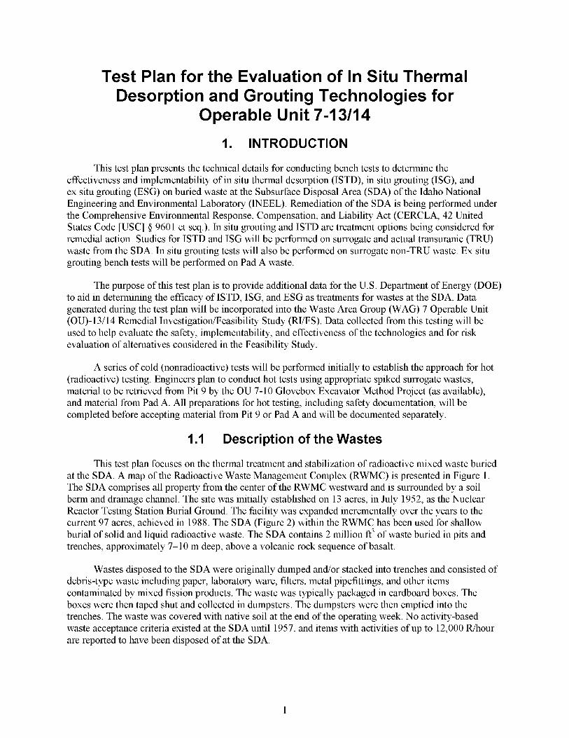
This test plan focuses on the thermal treatment and stabilization of radioactive mixed waste buried at the SDA. A map of the Radioactive Waste Management Complex (RWMC) is presented in Figure 1. The SDA comprises all property from the center of the RWMC westward and is surrounded by a soil berm and drainage channel. The site was initially established on 13 acres, in July 1952, as the Nuclear Reactor Testing Station Burial Ground. The facility was expanded incrementally over the years to the current 97 acres, achieved in 1988. The SDA (Figure 2) within the RWMC has been used for shallow burial of solid and liquid radioactive waste. The SDA contains 2 million ft3 of waste buried in pits and trenches, approximately 7-10 m deep, above a volcanic rock sequence of basalt.
Wastes disposed to the SDA were originally dumped and/or stacked into trenches and consisted of debris-type waste including paper, laboratory ware, filters, metal pipefittings, and other items contaminated by mixed fission products. The waste was typically packaged in cardboard boxes. The boxes were then taped shut and collected in dumpsters. The dumpsters were then emptied into the trenches. The waste was covered with native soil at the end of the operating week. No activity-based waste acceptance criteria existed at the SDA until 1957, and items with activities of up to 12,000 Rhour are reported to have been disposed of at the SDA.
1


Rocky Flats Plant (RFP) TRU waste was also disposed of in the SDA. The RFP wastes consisted of debris-type wastes and process sludges containing oil and chlorinated solvents adsorbed onto calcium silicate. The sludge and debris, including cloth, metal, wood, asphalt, glass, and plastic were containerized in metal drums or wooden crates and stacked horizontally in pits and trenches among the mixed/fission-product wastes from the SDA.
In situ thermal desorption is focused on remediating the chlorinated organics (methylene chloride, trichloroethylene [TCE], 1,1,1 trichloroethane [TCA], and carbon tetrachloride) in the organic sludge and the nitrate salts. In situ grouting and ESG can physically stabilize waste and retard migration of most hazardous inorganics and radionuclides. In addition, ISG-treated areas of the SDA (and ESG waste forms where they are reburied) will support hture capping components and minimize subsidence.
1.2 Contaminants of Concern
The Ancillary Basis for fisk Analysis for the Subsurface Disposal Area (ABRA) (Holdren et al. 2002) identified human health and potential ecological contaminants of concern (COCs) associated with buried waste. The exposure pathway with the majority of the COCs and highest risk was groundwater ingestion. Other pathways having unacceptable risk from one or more COCs include soil ingestion, inhalation, external exposure, and crop ingestion from surface uptake. Because it is presumed that an engineered barrier would be included as part of any selected remedy, which would mitigate surface exposure pathways that contribute to human risk, the OU 7-13/14 RI/FS will focus on remediating specific COCs that represent groundwater risk. Groundwater COCs are concentrated in several waste forms as follows:
0 Actinides. The majority of the actinides are contained in the RFP sludge buried within the TRU pits and trenches and Pad A.
0 Activation and Fission Products. Waste streams containing activation and mixed fission products consist mainly of metal, reactor core components, resins, and irradiated he1 material.
VOCs. The VOC COCs are contained in the RFP organic sludge and are located in the TRU pits and trenches.
Nitrates. SDA nitrates are contained in the RFP sludge and are located in Pad A and the TRU pits.
Results of the risk assessment were presented in the ABRA. The COCs addressed in this test plan consist of constituents identified in the ABRA and the Second Revision to the Scope of Work for the OU 7-13/14 Waste Area Group 7 Comprehensive Remedial Investigation Feasibility Study (INEL 1995) for the groundwater-exposed pathway exhibiting a hazard index greater than 1 or a carcinogenic risk greater than or equal to 1 x The COCs are presented in Table 1.
Table 1. Human health COCs from groundwater innestion. Contaminant of Concern Risk Range Hazard Index
Am-241, C-14, C1-36,I-129, Nb-94, Np-237, Tc-99, U-233, Cumulative Not Applicable
methylene chloride Pu-238, Pu-239, and Pu-240 Special Case Not Applicable
U-234, U-235, U-236, U-238, carbon tetrachloride and > i 10”
Carbon tetrachloride, nitrate salts, and tetrachloroethylene Not Applicable >1
Note 1: Peak risk values are from Table 7-1 of the ABRA. Note 2: The individual peak risk values rage from >IO9 to >IO3; the cumulative peak risk is therefore >IO3 (BRA).
3

2. SCOPE
This test plan is designed to obtain data to evaluate the safety and viability of ISTD, ISG, and ESG treatment options for wastes buried at the SDA. Data generated during the test plan will be incorporated into the pending WAG 7 OU-l3/14 Remedial Investigation/Feasibility Study, prepared for the DOE Idaho Operations Office (DOE-ID).
Studies and investigations conducted during the RI/FS are considered removal actions by EPA and are undertaken pursuant to Section 104(b) of CERCLA. As such, it is EPA’s policy that the RI/FS-related activities described in this test plan, when conducted onsite, will comply with applicable or relevant and appropriate requirements (ARARs) “to the extent practicable, considering the exigencies of the situation” (Federal Register, Volume 55, No. 46, March 1990, 8756). A listing of ARARs will be developed and presented in the project waste management plan (Section 9) to ensure protective and compliant management of investigation-derived waste and test residuals associated with this test plan. It is noted here (and is discussed hrther in the project waste management plan) that investigation-derived waste transported to off-Site locations (i.e., off the INEEL site) must comply with applicable requirements of the CERCLA off-Site Rule (40 CFR 300.400, “Procedures for Planning and Implementing Off-Site Response Actions”).
If additional test objectives are required, this test plan may be revised to include those objectives, or the objectives will be added to a hture test plan.
2.1 Application of In Situ Thermal Desorption
The ISTD portion of this test plan is designed to obtain laboratory and bench data necessary to determine if thermal desorption is a viable treatment option for the wastes buried at the SDA. Lab testing will also generate samples for testing effectiveness of grouting waste that has undergone thermal desorption. Up to this point, ISTD has been applied only to organic contaminated soil sites (this work has been successhl at bench and field scale) (Vinegar et al. 1998 and Vinegar 1997). Buried containerized waste, radioactive metals, and nitrate salts have not yet been treated by ISTD. In situ thermal desorption is being considered for areas in the SDA with high organics.
The ISTD process under consideration uses electric resistance heaters to heat a region of the subsurface soil (see Figure 3) and waste to a prescribed temperature. Vapors generated by this heating process are collected by an aboveground off-gas system. In situ thermal desorption can reduce the amount of contaminants in the subsurface by volatilization or, at higher temperatures, by degradation.
In most applications of ISTD, two types of boreholes are used. One type provides heat and vapor removal; it contains an electrical resistance heater surrounded with coarse sand to ensure good thermal contact between the heater and the subsurface and to maintain an annulus of high permeability for the removal of vapor from the heated zone. The second type of borehole provides heat only; it also contains an electrical resistance heater surrounded with coarse sand, but is closed at the surface. Heating boreholes are placed around heatinghapor removal boreholes (see Figure 3). The heaters in the boreholes operate at temperatures of 400-825°C. The temperatures in the surrounding waste zone (the process temperatures) can be significantly below the heater temperature. Contaminants are moved from the ambient temperature outer regions toward the hotter treatment region and the borehole by applying a slight vacuum to the borehole. In situ thermal desorption can be done at a range of temperatures. The process temperature for applying ISTD to SDA wastes has not been selected, so a range of temperatures up to 450°C will be tested.
4
Filter
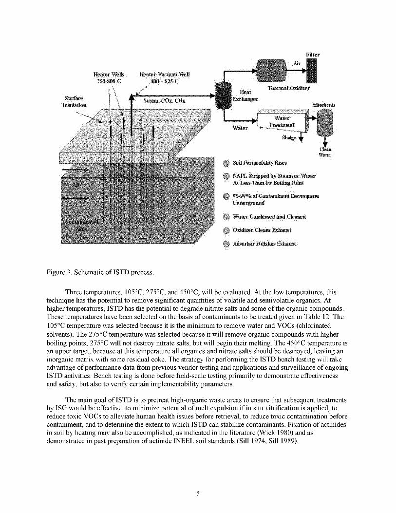
Figure 3 . Schematic of ISTD process
Three temperatures, 105"C, 275"C, and 450"C, will be evaluated. At the low temperatures, this technique has the potential to remove significant quantities of volatile and semivolatile organics. At higher temperatures, ISTD has the potential to degrade nitrate salts and some of the organic compounds. These temperatures have been selected on the basis of contaminants to be treated given in Table 12. The 105°C temperature was selected because it is the minimum to remove water and VOCs (chlorinated solvents). The 275°C temperature was selected because it will remove organic compounds with higher boiling points; 275°C will not destroy nitrate salts, but will begin their melting. The 450°C temperature is an upper target, because at this temperature all organics and nitrate salts should be destroyed, leaving an inorganic matrix with some residual coke. The strategy for performing the ISTD bench testing will take advantage of performance data from previous vendor testing and applications and surveillance of ongoing ISTD activities. Bench testing is done before field-scale testing primarily to demonstrate effectiveness and safety, but also to verify certain implementability parameters.
The main goal of ISTD is to pretreat high-organic waste areas to ensure that subsequent treatments by ISG would be effective, to minimize potential of melt expulsion if in situ vitrification is applied, to reduce toxic VOCs to alleviate human health issues before retrieval, to reduce toxic contamination before containment, and to determine the extent to which ISTD can stabilize contaminants. Fixation of actinides in soil by heating may also be accomplished, as indicated in the literature (Wick 1980) and as demonstrated in past preparation of actinide INEEL soil standards (Sill 1974, Sill 1989).
5

An additional goal of the bench-scale testing is to determine the off-gases generated by the process to support hll-scale system design. Although the formation of chlorinated organic compounds, such as dioxidhrans has been observed in incinerators, their formation downstream of the ISTD thermal oxidizer has never been observed. Dioxins/hrans are generated in a temperature range of 2O0-45O0C, so there is a potential for dioxidhran formation using ISTD. There are several potential sources of chlorine: volatile organic compounds (VOCs), plastic from PPE and trash, and sodium chloride in the nitrate salts. The VOCs have relatively low boiling points and are expected to be removed below 200°C (most will come off with the water at 100°C). The chloride from the plastic and nitrate salts could be available in the 200-450°C range, however, the ISTD system operates under low oxygen conditions, laminar flow, and long residence times, all of which do not favor dixodhran formation. In addition, the off-gas processing that will be a part of the ISTD system will include a thermal oxidizer unit that will destroy any organic compounds (including dioxirdhrans) exiting the borehole. The testing of the off-gas stream (before a thermal oxidizer) during the drum scale testing of ISTD with organics and nitrate salts will include analysis for dioxins and hrans.
Other COCs such as C-14, Tc-99,I-129, and Nb-94, though not directly targeted by ISTD, are present in wastes buried at the SDA. These elements would also be affected by the heating process. Carbon and iodine may be found in the off-gas, but Tc-99 and Nb-94 may also be immobilized by the heating process based on their chemistry and INEEL soil structure (Sill 1974). The effectiveness of ISTD in removing COCs and fixing metals will be the target of this testing. In evaluating ISTD for application to specific wastes, some of the aspects to be considered include the following:
Heated Waste Interactions. Potential reactive interactions between combustible debris, organic sludge, and nitrate salt sludge, must be investigated. A primary safety (implementability) factor for ISTD is heating waste materials, such as nitrate salts, next to paper and machine cutting oils without causing uncontrolled reactions. Since these wastes are present in the TRU pits and trenches, reactivity of nitrates and organic material will be determined in a series of assessment tests.
Degree of Organic Destruction. The ability for ISTD to remove or destroy organic and chlorinated organic COCs is a major reason for testing. The degree to which these contaminants are removed will depend on the temperature applied and the specific COC.
Fixation ofActinides. The ability of heat to fix actinides will be determined through bench testing. Fixation may occur on the waste residue or on soil. Past work indicates an effective fixation of actinides to a soil matrix upon heating (Wick 1980; Sill 1974, 1989).
Gas Evolution and Temperature of Operation. A range of temperatures will be studied. Gases generated during heating will be used to monitor the heating process.
Physical Stability. The post-ISTD site may require hrther stabilization by ISG to fill voids in the waste and associated soils. Heated samples will be prepared for grout testing. The ISTD material will vary from an ash form to a greaselike substance. Depending upon the matrix, grout will be mixed in different ways from blenders to paddle-wheel mixers. The grout vendors will be used to direct mixing of the grouts and identify interferences.
Contaminant Release during In Situ Thermal Desorption and Secondary Waste Generation. All aspects of the in situ heating process must be examined to evaluate the potential for contaminant release to the environment from both the well emplacement operation and during treatment. The off-gas system will be designed to prevent particulates from being released to the atmosphere. The
6

gas types generated will be investigated. The performance of designed safety systems (collection well and off-gas systems) must be evaluated against safety and as low as reasonably achievable (ALARA) goals established for the project.
2.2 Application of In Situ Grouting
This test plan is designed to obtain data necessary to evaluate the effectiveness of ISG to treat the waste buried at the SDA. It will also determine the effectiveness of grouting waste that has undergone thermal desorption first. While in situ grouting can be accomplished via several methods, for the SDA, in situ jet grouting has been determined to be most appropriate. Permeation grouting at low pressure with beam vibration has been tested on surrogate waste. The INEEL undisturbed soils are very tight. Good mixing of the waste and grout was difficult to accomplish. Also, areas of heavy debris (such as constitute most of the SDA) hindered flow; therefore, in this test plan, ISG refers to in situ jet grouting. ISG uses a specially designed rotary percussion drill rig to deliver and intimately mix grout with soil, debris, and contaminants in the subsurface (Figure 4 presents a preconceptual schematic of the overall system. The sheet piles would be placed at the edge of the region to be grouted and there would be some space between the jet grouting nozzle and the sheet pile.). The grout is injected at approximately 6,000 psi through small nozzles. Information gathered in previous testing (Technology for Application in Buried Transuranic Waste Sites, INEEL/EXT-02-0233, Rev. 0 August 2002) indicates that the jet grouting process will not always cut through a waste drum. (To cut through a waste drum, the nozzle must be very close to the drum and the jet must be in contact with the drum long enough to erode or puncture the drum. Corroded metal is easier to cut through than noncorroded metal.) The jet grouting process, therefore, is accomplished on a 20411. triangular pitch matrix, which guarantees that each 55-gal drum will be punctured and filled with as much grout as the voids in the drum will allow. In addition, with that matrix, each large box will be punctured with multiple application of the grout. This high pressure combined with the dense grout provides the energy required to mix the grout and subsurface materials. Each injection of grout in homogenous soil forms a cylinder and a series of diagonally offset columns is used to form a continuous monolith. Injection of grout in nonhomogenous waste can form an extensive monolith beyond the immediate cylinder depending on voids and types of containers. Multiple injections intersect to form a continuous monolith. Grouts must be specially designed for ISG to meet the viscosity, particle size, and set times required for effective operation of the grouting rig. Past bench- and field-scale testing have demonstrated the feasibility of the four grouts being tested.
The ISG process has been demonstrated for application only to buried waste containing actinides and hazardous wastes found in the TRU pits and trenches. The ISG process has not yet been demonstrated for non-TRU waste (non-TRU Pits 7, 8, 13-16; Trenches 11-58; and Soil vault rows 1-20) that contains gamma or beta radiation sources and which poses a potential health and safety threat to operational personnel. In situ grouting is being considered for general SDA application.
The main goal for ISG is physical stabilization of waste and immobilization of COCs. To establish the suitability of the ISG as a possible waste treatment applicable to the SDA, the grouting process and/or the resultant grout/waste monolith must exhibit the following attributes:
0 Monolith Durability. The life expectancy of the in situ grout material to provide protection to human health and the environment will be inferred through testing and empirical derivations from its dissolution during leach testing. Matrices such as waste or soil may interfere with and interact with the grout. The resultant monolith is expected to be a complicated heterogeneous mixture of pockets of neat grouts, competent regions of grouts and waste, and even regions in which the amount or type of waste and soil (interferent) may retard curing or detract from grout performance; however, over all, the expected net effect is a large decrease in hydraulic conductivity over the acres of buried waste at the SDA and a complete elimination of the potential for subsidence.
7
Vent
L Drill rig
1 1 Building II I I
03-GA50030-03
System in Jet Grouting Mode
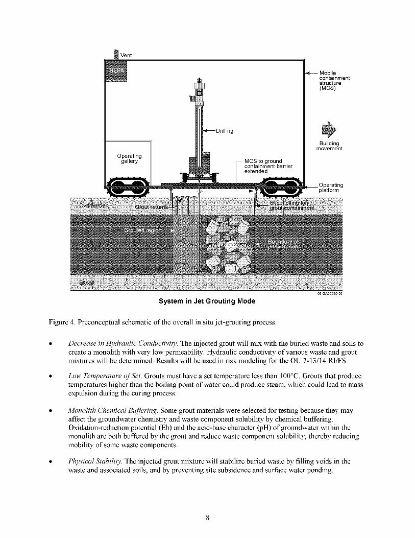
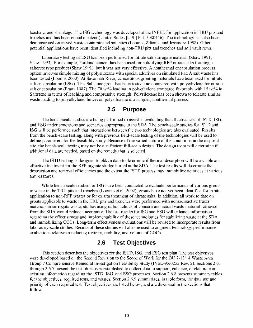
Figure 4. Preconceptual schematic of the overall in situ jet-grouting process.
0 Decrease in Hydraulic Conductivity. The injected grout will mix with the buried waste and soils to create a monolith with very low permeability. Hydraulic conductivity of various waste and grout mixtures will be determined. Results will be used in risk modeling for the OU 7-13/14 RI/FS.
Low Temperature of Set. Grouts must have a set temperature less than 100°C. Grouts that produce temperatures higher than the boiling point of water could produce steam, which could lead to mass expulsion during the curing process.
Monolith Chemical Buffering. Some grout materials were selected for testing because they may affect the groundwater chemistry and waste component solubility by chemical buffering. Oxidation-reduction potential (Eh) and the acid-base character (pH) of groundwater within the monolith are both buffered by the grout and reduce waste component solubility, thereby reducing mobility of some waste components.
0 Physical Stability. The injected grout mixture will stabilize buried waste by filling voids in the waste and associated soils, and by preventing site subsidence and surface water ponding.
8

0 Minimize Contaminant Release during ISG. All aspects of the grout emplacement process must be examined to evaluate the potential for contaminant release to the environment from the operation. The performance of designed safety systems must be evaluated against safety and ALARA goals established for the project.
0 GroutMaste Compatibility. Waste matrices such as nitrate salts and organic sludges, when mixed with grout, may interfere with grout curing. It is important to use grouts that are tolerant of these interferences (good monolith formation and low hydraulic conductivity).
0 Encapsulate Contaminants. The grout material should encapsulate the waste components.
2.3 Application of Ex Situ Grouting
Ex situ grouting (ESG) is being considered for treatment of the Pad A salt waste, which is stored on an asphalt pad on the ground surface. Ex situ grouting includes selection of an appropriate grout and the design of an approach to transfer the waste from Pad A to a mixing system where existing containers could be opened, the waste contents mixed with grout, and waste-grout mix placed in containers for disposal. This test plan only addresses the selection of an appropriate grout for the stabilization of Pad A salt waste. Two candidate grouts have been identified for testing on the actual Pad A waste.
The main goal for ESG of Pad A salts is to reduce mobility of uranium, a major COC associated with the nitrate salts. To establish the suitability of the ESG option as a possible waste treatment applicable to the salts, the grouthalt waste form must exhibit the following:
0 Monolith Durability. The grout and salt waste form should maintain its physical stability and encapsulation properties for a time frame of significant magnitude relative to the expected duration of the COCs.
0 Physical Stability. A successhl grout/waste mixture will have minimal voids and a minimum unconfined compressive strength of 50 psi. Testing will compare each grout’s performance.
0 GroutMaste Compatibility. The grout must be compatible with the salt waste matrix. It is essential for the grout to tolerate high salt loadings.
0 Encapsulate Contaminants. The grout material must encapsulate the salts and minimize mobility of COCs - ANS 16.1 for radionuclides and TCLP for EPA toxic metals.
2.4 Past Work
In situ thermal desorption has features that make it a viable process alternative for remediation of WAG 7 VOCs. Since this removal is purely temperature dependent and independent of physical factors and based on limited field testing, it should be robust enough for operation in metals, debris, and containerized waste as well as soil (Shaw 1999). The treatment destroys targeted organic COCs, other organic chemicals, and nitrate salts. It will also destroy organic materials such as polyethylene, polyvinyl chloride, latex, paper, ion exchange resins, solvents, machine oil, asphalt, and heavy oils in the waste and soil. In situ thermal desorption will decompose most organics and all inorganic nitrate salts if temperatures are allowed to go beyond 400°C. It will sinter the SDA soils (fine-grained, approximately 40% clay, 50% silt, and 10% sand), permanently altering the soil structure.
Many of the basic physical data for ISG have already been obtained for the various grouts (Loomis 2002). These parameters include hydraulic conductivity, compressive strength, tensile strength, heat of hydration, initial and final gel times, pressure filtration, viscosity, density, Eh and pH in the
9
leachate, and shrinkage. The ISG technology was developed at the INEEL for application in TRU pits and trenches and has been issued a patent (United States [U.S.] Pat. 5980446). The technology has also been demonstrated on mixed-waste contaminated soil sites (Loomis, Zdinals, and Jessmore 1998). Other potential applications have been identified including non-TRU pits and trenches and soil vault rows.
Laboratory testing of ESG has been performed for nitrate salt surrogate material (Shaw 1991; Shaw 1993). For example, Portland cement has been used for solidifying RFP nitrate salts forming a saltcrete type product (Shaw 1991), but it was not very effective. A nonthermal encapsulation process option involves simple mixing of polysiloxane with special additives on simulated Pad A salt waste has been tested (Loomis 2000). At Savannah fiver, cementitous grouting materials have been used for nitrate salt encapsulation (ESG). This Saltstone grout has been tested and compared with polyethylene for nitrate salt encapsulation (Franz 1987). The 70 wt% loading in polyethylene compared favorably with 15 wt% in Saltstone in terms of leaching and compressive strength. Polysiloxane has been shown to tolerate similar waste loading to polyethylene; however, polysiloxane is a simpler, nonthermal process.
2.5 Purpose
The bench-scale studies are being performed to assist in evaluating the effectiveness of ISTD, ISG, and ESG under conditions and scenarios appropriate to the SDA. The bench-scale studies for ISTD and ISG will be performed such that interactions between the two technologies are also evaluated. Results from the bench-scale testing, along with previous field-scale testing of the technologies will be used to define parameters for the feasibility study. Because of the varied nature of the conditions in the disposal site, the bench-scale testing may not be a sufficient hll-scale design. The design team will determine if additional data are needed, based on the remedy that is selected.
The ISTD testing is designed to obtain data to determine if thermal desorption will be a viable and effective treatment for the RFP organic sludge buried at the SDA. The test results will determine the destruction and removal efficiencies and the extent the ISTD process may immobilize actinides at various temperatures.
While bench-scale studies for ISG have been conducted to evaluate performance of various grouts to waste in the TRU pits and trenches (Loomis et al. 2002), grouts have not yet been identified for in situ application to non-RFP wastes or for ex situ treatment of nitrate salts. In addition, all work to date on grouts applicable to waste in the TRU pits and trenches were performed with nonradioactive tracer materials in surrogate waste; studies using radionuclides of concern and actual waste material retrieved from the SDA would reduce uncertainty. The test results for ISG and ESG will enhance information regarding the effectiveness and implementability of these technologies for stabilizing waste at the SDA and immobilizing COCs. Long-term effectiveness evaluations will be revised to incorporate results from laboratory-scale studies. Results of these studies will also be used to augment technology performance evaluations relative to reducing toxicity, mobility, and volume of COCs.
2.6 Test Objectives
This section describes the objectives for the ISTD, ISG, and ESG test plan. The test objectives were developed based on the Second Revision to the Scope of Work for the OU 7-13/14 Waste Area Group 7 Comprehensive Remedial Investigation Feasibility Study (INEL-95/0253 Rev. 2). Sections 2.6.1 through 2.6.7 present the test objectives established to collect data to support, enhance, or elaborate on existing information regarding the ISTD, ISG, and ESG processes. Section 2.6.8 presents summary tables for the objectives, required tests, and wastes. Section 2.6.9 summarizes, in table form, the data use and priority of each required test. Test objectives are listed below, and are discussed in the sections that follow:
10
1.
2.
3 .
4.
5 .
6.
7 .
Develop data to support contaminant transport modeling for treated waste forms
Evaluate durability of grouted waste
Evaluate release of radionuclide particulate during grouting
Evaluate WaxfixB for use as a grout
Quantify major emissions as wastes and soils are slowly heated
Determine the degree of hazardous organic contaminant and nitrate removal and/or destruction from soil and waste
Test potential mixtures of organics and nitrates for reactivity.
2.6.1 Develop Data to Support Contaminant Transport Modeling for Treated Waste Forms
2.6.7.7 Applicability
0 ISTD of TRU pits and trenches
0 ISG of ISTD pretreated TRU pits and trenches
0 ISG of TRU pits and trenches
0 ISG of non-TRU pits and trenches and soil vault rows
0 ESG of Pad A salts.
2.6.7.2 contaminants in the final waste form after ISG or ESG. In addition, these data will be used to determine changes in leachability of actinides from the waste and surrounding soil following ISTD heating.
2.6.7.3 baseline compositional data for all other tests.
Purpose. Data obtained from these tests will be used in the modeling of migration of
Required Tests. Compositional analysis of Pad A wastes and waste from Pit 9 will provide
Compressive strength will be used as an objective standard to be used for defining a cohesive (that is stand-alone) monolith and determining the maximum waste loading for a grout. Previous work with grout/waste mixtures has shown that unconfined compressive strength is a good indicator for a cohesive monolith and a good predictor for maximum waste loading for a grout. This testing applies to ISG-treated wastes and will be done using cold surrogates.
Hydraulic conductivity will be measured for ISG-treated wastes using cold surrogates. The hydraulic conductivity measurements will indicate the potential for water to move through a grouted waste form.
Porosity will be estimated for ISG-treated wastes using cold surrogates. The porosity measurements will provide data on the size and degree of connection of the pores in the grouted waste forms; this information helps in discerning the potential for water transport through the grouted waste form.
11
Fracture propagation evaluation of the ISG-treated wastes will also be performed using cold surrogates. The fracture propagation tests will estimate the aperture and distribution of the cracks in a grouted waste form. Understanding the fracture propagation is important for estimating the relative surface area to volume ratio that will exist in grouted waste forms in the future. This ratio is important to estimating the diffusion pathway for contaminants, and is an important parameter for modeling.
The potential for the release of gas-phase VOCs from mixtures of WaxfixB for ISG will be evaluated in two ways. Microencapsulation tests will involve intimate mixing of the WaxfixB and organic compounds. Macroencapsulation tests will involve the placement of a pocket of organic compound within a block of WaxfixB. Both tests will be performed using cold surrogates in a sealed gas chamber.
Leachability will be determined for ISTD-, ISG-, and ESG-treated wastes using the accelerated version of American Nuclear Society (ANS) 16.1 (American Society for Testing and Materials [ASTM] 1992), Kd, or toxicity characteristic leaching procedure (TCLP), as appropriate. Cold and hot surrogates, in addition to actual waste, will be used in these tests. The leach testing will provide data on the release rate of contaminants from the treated waste.
Measurement of Eh and pH will give an indication of the chemical buffering of the final in situ waste form. These tests will be done on the leachate from leaching tests conducted for ISTD- and ISG-treated wastes using hot surrogates or actual waste.
2.6.1.4 from the treated waste and compare it to the predicted release rate from untreated waste. The test results will also support the risk assessment, risk model, and performance evaluation portion of the OU 7-13/14 Feasibility Study. The data quality must be sufficient to establish the estimated release rates for contaminants that remain on soil and waste matrices after treatment.
Data Use. These data will support modeling to estimate the release rate of contaminants
2.6.2 Evaluate Durability of Grouted Waste
2.6.2.1 Applicability
0 ISG of TRU pits and trenches
0 ISG of ISTD treated TRU pits and trenches
2.6.2.2 grouted waste form for short-term tests.
ISG of non-TRU waste pits and trenches and soil vault rows.
Purpose. To provide data to compare grouts and infer the long-term physical stability of the
2.6.2.3 the grouted waste form to compression while in the subsurface. These data will help establish the magnitude of physical stresses required to promote fracture propagation. These tests will be done for ISG waste forms using cold surrogates.
Required Tests. Compressive strength of grouted waste forms estimates the resistance of
Hydraulic conductivity will be measured for ISG-treated wastes using cold surrogates. The hydraulic conductivity measurements will indicate of the potential for water to move through a grouted waste form.
Porosity will be estimated for ISG-treated wastes using cold surrogates. The porosity measurements will provide data on the size and degree of connection of the pores in the grouted waste
12
forms; this information helps in discerning the potential for water transport through the grouted waste form.
Fracture propagation evaluation of the grout waste forms (ISG treated waste) will be performed using cold surrogates. The cold surrogates will be either neat grout or grout mixed with surrogate waste. The fracture propagation tests will estimate the aperture and distribution of the cracks in a grouted waste form. These data are important to help estimate the potential for preferential pathways for water to develop within the grouted waste form.
Measurement of Eh and pH will give an indication of the chemical buffering of the final in situ waste form. These tests will be done on the leachate from leaching tests conducted for ISG- and ESG-treated wastes using hot surrogates or actual waste.
2.6.2.4 physical stability of the grouted waste forms. Hydraulic conductivity for all of the grouts except WaxfixB was completed previously (Loomis 2002).
Data Use. The physical property data from these tests will be used to predict the long-term
2.6.3 Evaluate the Release of Radionuclide Particulate During Grouting
2.6.3.1 Applicability
0 ISG of TRU pits and trenches
0 ISG of ISTD treated TRU pits and trenches.
2.6.3.2 TRU pits and trenches. A primary issue is the aerosolization of plutonium fines from soilcretegrout returns associated with the grouting process. Grout returns are mixtures of neat grout and soil or other material within the waste seam that has come to the surface via the annulus formed by the waste and the drill steel. In the present case, the management of grout returns has been greatly simplified by the use of an xyz positional system suspended by bridge crane above the waste pit or trench. Using this system, grout returns are actually encouraged as an indicator of complete void filling in the waste.
2.6.3.3 glovebox using actual plutonium fines (hot surrogate) mixed with grout and soil. The release of plutonium will be measured from mixtures of grout/soil/contaminant mixture that have set. An airflow will be applied to the samples and the amount of plutonium entrained in the airflow will be measured. The final test design will be completed after additional discussions with the engineers raising the safety issue and the laboratory personnel performing the test. The airflow rate and the amount of abrasive action during the airflow are important considerations in test design. The test will be conducted in a glovebox (or similar appropriate containment) with a pump to control the airflow and filtratiodcollection system to capture particulates. An Anderson impact filter (or similar instrument) will be used to collect and determine the size distribution of the particulate.
2.6.3.4 Data Use. If it can be shown that essentially no aerosolization of plutonium originates from the cured grout return during the jet grouting process, design engineers can take credit for the cured grout return as a barrier to contaminant spread, which can simplify the design of the grout delivery system.
Purpose. This task will investigate the potential spread of contaminants while grouting
Required Tests. Plutonium aerosolization will be evaluated using a specially designed
2.6.4 Evaluate WaxfixB for Use as a Grout
2.6.4.1 Applicability
0 ISG of TRU pits and trenches
13
0 ISG of ISTD treated TRU pits and trenches
0 ISG of non-TRU waste pits and trenches and soil vault rows
0 ESGofPadA.
2.6.4.2 WaxfixB as an in situ grout for TRU and non-TRU wastes since WaxfixB has not been as extensively tested as the other in situ grouts proposed in this test plan.
Purpose. The purpose of these tests is to better understand the advantages and limitations of
2.6.4.3 surrogates. One of the issues is that the moderating properties of WaxfixB grout could increase the potential for a criticality in the TRU pits and trenches. The solution to this potential issue is the addition of Boron- 10 (a poison for nuclear reactions) at 1 g/L in the molten wax and ensuring that the distribution remains at that concentration during the cooling process (up to 5 days in duration). The concentration of boron- 10 is based on criticality calculations for emplacement in and around a postulated critical mass of Pu-239 (Farnsworth et al. 1999, INEEL 1999). The boron-10 is essentially inert in the wax and is expected to be functional as long as the WaxfixB. Information coming from a criticality review (documentation forthcoming) of the application of grout and wax in the SDA may eliminate the need for the boron. The laboratory tests will include slow (5-day) cooling of WaxfixB with boron-10 alone and slow cooling of WaxfixB with boron-10 that has migrated into a column of soil. The purpose of the soil test is to access the potential for boron-10 to be filtered from the WaxfixB as it migrates from the original placement site during cooling (this would be an issue mainly at the edges of a monolith).
Required Tests. Boron retention and distribution in WaxfixB will be tested using cold
Compressive strength will be measured for wastes (cold surrogates) grouted with WaxfixB. The compressive strength results will define the formation of a freestanding monolith.
Hydraulic conductivity will be measured for ISG-treated wastes using cold surrogates. The hydraulic conductivity measurements will indicate the potential for water to move through a grouted waste form.
Another issue is the oxidizer potential of the nitrate salts on the added WaxfixB material within the TRU pits and trenches. A Department of Transportation (DOT) oxidizer test on the mixtures of WaxfixB and nitrate salts (cold surrogate) will determine if there is any potential reactivity.
The potential for the release of gas phase VOCs from mixtures of WaxfixB and waste will be evaluated in two ways using cold surrogates. Microencapsulation tests will involve intimate mixing of the WaxfixB and organic compounds. Macroencapsulation tests will involve the placement of an organic compound mass within a block of WaxfixB. Both tests will be performed in a sealed gas chamber.
The potential for hydrogen gas generation because of radiolysis in paraffin-based grout materials will be assessed by using samples of WaxfixB mixed with radionuclides (hot surrogates) in a sealed chamber and measuring for hydrogen release to the chamber. Hydrogen gas generation is not thought to be a major problem in WaxfixB solidification but will be studied in the literature to verify projected rates of formation for alpha attack on saturated hydrocarbons. The formation of large quantities of gas in wax will be mitigated by the diffusion of the hydrogen through the WaxfixB. The hydrogen gas generation test will provide an estimate of the rate of hydrogen generation from the interaction of radionuclides with WaxfixB. This estimate will be used to determine if hydrogen formation is an issue of concern for WaxfixB in the radiation fields expected to be generated by the waste.
14
2.6.4.4 Data Use. The data will be used to address potential criticality and reactivity concerns that may be encountered with specific types and concentrations of contaminants and to determine the off-gas potential of mixtures of WaxfixB and VOCs to assess the migration of VOCs from grouted buried waste sites. In addition, the hydrogen gas generation rate of WaxfixB mixed with radionuclides because of the radiolysis process will be assessed.
2.6.5 Quantify Major Emissions as Wastes and Soils are Slowly Heated
2.6.5.1 Applicability
0 ISTD of TRU pits and trenches wastes.
2.6.5.2 heated for off-gas design, and monitoring the ISTD process.
2.6.5.3 provide baseline compositional data for all other tests.
Purpose. Determine primary off-gas constituents and concentrations as wastes and soils are
Required Tests. Compositional analysis of Pit 9 wastes (TRU pits and trenches waste) will
Emissions will be measured while heating soil and wastes. During waste heating, hazardous organics and cold and hot surrogates for nitrates are both decomposed and volatized. Most destruction occurs in the ground with some organics and a variety of inorganic gases passing through the off-gas treatment system (Vinegar 1998). The off-gas system must be able to destroy the trace organics and must resist corrosive acidic gases (HC1, NO,, and possibly SO2) produced during the heating process. The off-gas concentrations of NO,, CO, SO2, C02 and HC1 and particulates will be determined as temperature is raised at different rates. Portable multihnction combustion analyzers can directly measure these gases. Samples can also be obtained by dissolution of the gases in slightly basic water and the anions (NO3-, -NO2-, -SO3-, and C1 -) determined by standard ion chromatography. This method is the same as used on the solid samples to determine residual nitrates. Tracer concentrations in particulates will be determined by inductive coupled plasma mass spectrometry.
A mass balance will be calculated based on analysis of the sample material after heating and the emissions measurements.
2.6.5.4 Data Use. The data will help identify the off-gas processing requirements for hll-scale test planning. The CO and C02 releases determine the relative amounts of combustion and pyrolysis occurring. The gas proportion measurements will also assist in monitoring the type of waste being heated and any nitrate organic reactions. In addition, these data will support the generation of safety and design data for the OU 7-13/14.
2.6.6 Determine the Degree of Hazardous Organic Contaminant and Nitrate Removal and/or Destruction from Soil and Waste
2.6.6.1 Applicability
2.6.6.2 the waste.
ISTD of TRU pits and trenches wastes.
Purpose. Quantify the removal and/or destruction of chlorinated VOCs and nitrate salts in
2.6.6.3 baseline compositional data for all other tests.
Required Tests. Pit 9 wastes (TRU pits and trenches waste) will be analyzed to provide
15
Samples will be analyzed at each temperature range to quantify chlorinated VOC and nitrate concentrations. This method involves purge and trap and gas chromatography (GC) analysis of a solid sample. Nitrate is determined by standard ion chromatography methods after dissolution of nitrates from solid residues into water. Postsample characterization will verify removal/destruction in both simulated and radioactive samples.
A mass balance will be calculated based on analysis of the sample material after ISTD treatment and the initial compositional analysis before ISTD treatment.
2.6.6.4 efficiency for COCs in the TRU pits and trenches wastes. The data will also be used to generate design data for the pending OU 7-13/14 Feasibility Study.
2.6.7
Data Use. The data will help establish anticipated ISTD mediated removal/destruction
Test Potential Mixtures of Organics and Nitrates for Reactivity
2.6.7.1 Applicability
2.6.7.2 exothermically during heating by ISTD.
ISTD of TRU pits and trenches.
Purpose. To determine if mixtures of nitrate salt sludge and organic sludge will react
2.6.7.3 destruction) the organic concentration to facilitate the implementation of ISG, reduce VOCs to facilitate implementation of in situ vitrification, reduce VOCs before capping, or reduce VOCs to minimize the risk during retrieval. The processing of organic sludge and nitrate sludge must not result in uncontrolled reactions that might breach the off-gas collection and treatment system.
Required Tests. In situ thermal desorption must be able to reduce (through removal or
The safety portion of this bench testing will be similar to that previously performed (Dick 1990, Shaw 2002). This work will be done using cold surrogates. Previous safety studies on in situ vitrification type heating have determined that phosgene formation is impossible under the slow heating conditions of ISTD and lack of precursors. Phosgene requires dry, high-temperature destruction of organic chlorides. Volatile organic compounds in organic sludge are all emitted with the steam; as such, they are not present in a dry, high-temperature environment. Modeling of ISTD on SDA organic waste verifies that phosgene formation is negligible at ISTD conditions with the volatile precursors (Myron Kuhlman 2003, ISTD Simulations for the INEEL RWMC SDA, MK Solutions, Houston, Texas). The slow heating does not contribute to uncontrolled reactions for the following reasons :
The volatile organic contaminants will be removed or destroyed before the temperature of combustion for the debris is reached. Differential scanning calorimetry tests will be conducted with combinations of nitrates and oil to better estimate the nature of the exothermic reactions between nitrates and oil.
There is a large temperature gap between organic pyrolysis (275°C) and nitrate decomposition (450°C)
0 There is lack of oxidizing material. There is insufficient air to provide for uncontrolled reactions (i.e., underground fire) and the oxygen that would be available from the decomposition of the nitrates is a fraction of that required to consume the combustible material.
Reactive mixtures of nitrate and organic material currently existing in the SDA are extremely unlikely. Nitrates are always packaged in discrete drums, as are organics (both debris and sludges).
16

No environmental mixing mechanism combines and intimately mixes these discrete waste streams. Furthermore, any mixing that might occur underground would, by definition, involve significant dilution with surrounding soil, water, and other waste. Less than 1% of organic sludge drums and nitrate drums are estimated to be co-located at a high (4 drums/m2) density or greater. Nitrate salts do not react with organic sludges even when a controlled drum-scale mixture is prepared and heated. The only existing reactive carbon sources in RWMC are graphite and paper debris. The former is much rarer than organic sludges. Graphite is usually found as chunks packed in discrete drums with no waste-driven internal-corrosion mechanism. Debris drums are low-density carbon sources with even less likelihood of mixing or flowing than a granular sludge or oily liquid (Becker et al. 1998, Clements 1982, Clements & Kudera 1985)
Safety testing being performed under this test plan will use internally heated nitrate organic mixtures to determine if exothermic reactions will occur.
Emission monitoring and post-sample characterization will be used to monitor the heating of simulated organic and nitrate-containing samples. Gases will be monitored, particularly NO,, during heating for reactivity assessment and to assist hture design and operation of the off-gas system.
2.6.7.4 establish temperature ranges where such reactions will not occur.
Data Use. The data will be used to determine if exothermic reactions occur and, if so, to
2.6.7.5 combinations are presented in Table 2 and Table 3 . Additional details on specific tests for each of the wastes and technologies are presented in Section 4.
Summary of Objectives. The test plan objectives and associated technology and waste
2.6.8 Data Use and Priority for Required Tests
Table 4 presents the data use and priority for each required test. A relative priority is indicated for the required tests based on the timeframe in which the data will be used. The data needed immediately for modeling, implementability, effectiveness, and safety is designated by an “I” in Table 4. The data that supports a more complete hndamental understanding of effectiveness or modeling in the longer term is designated by a “L” in Table 4.
17
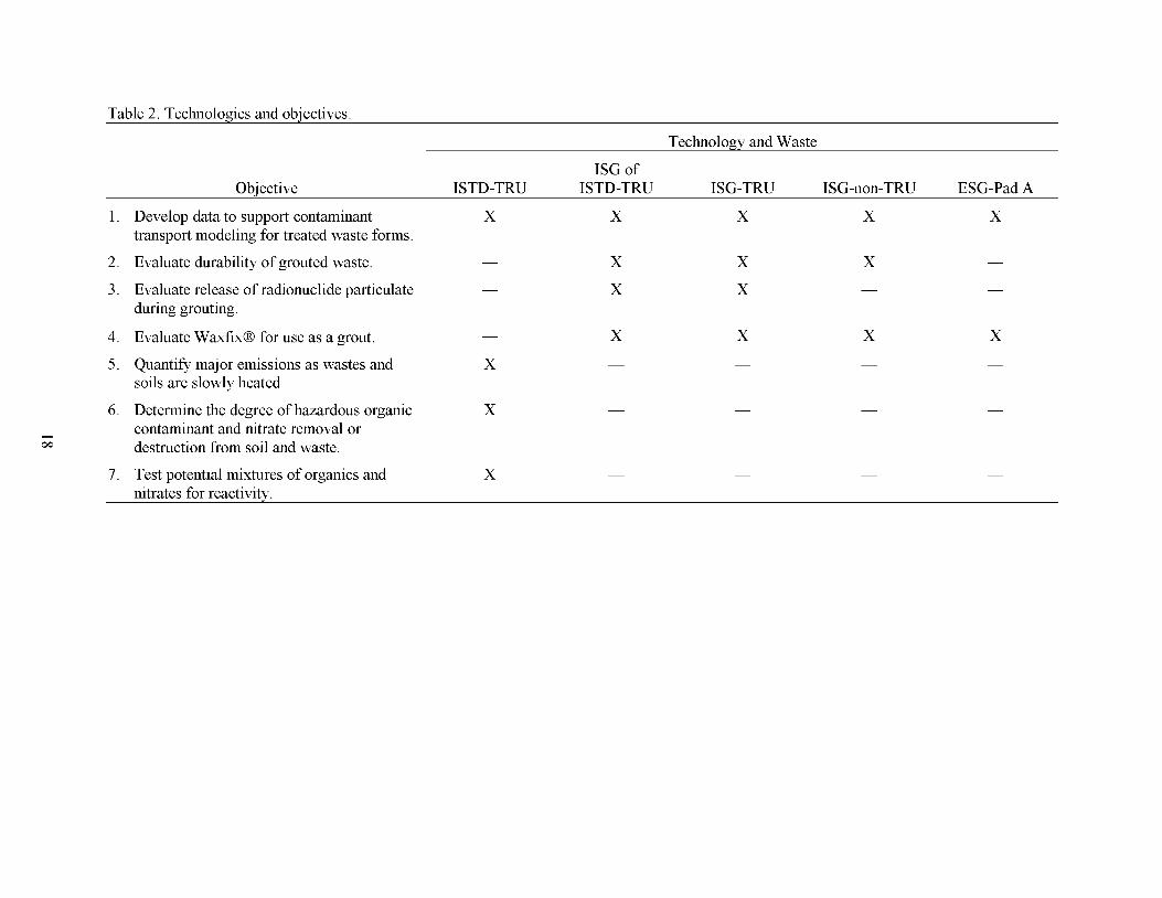
Table 2. Technologies and obiectives
Technoloav and Waste
ISG of Objective ISTD-TRU ISTD-TRU ISG-TRU ISG-non-TRU ESG-Pad A
1.
2.
3 .
4.
5 .
6.
7 .
Develop data to support contaminant transport modeling for treated waste forms.
Evaluate durability of grouted waste.
Evaluate release of radionuclide particulate during grouting.
Evaluate WaxfixB for use as a grout.
Quantify major emissions as wastes and soils are slowly heated.
Determine the degree of hazardous organic contaminant and nitrate removal or destruction from soil and waste.
Test potential mixtures of organics and
-
X
X
X
X
X
X
X -
X
X
X
X -
X
X -
X -
nitrates for reactivity.
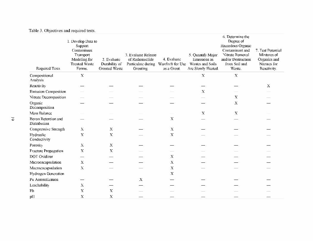
Table 3 . Obiectives and reauired tests. 6. Determine the
Degree of 1. Develop Data to support Hazardous Organic
Contaminant Contaminant and 7. Test Potential Transport 3. Evaluate Release 5 . Quantify Major Nitrate Removal Mixtures of
Modeling for 2. Evaluate of Radionuclide 4. Evaluate Emissions as and/or Destruction Organics and Treated Waste Durability of Particulate during Waxfix@ for Use Wastes and Soils from Soil and Nitrates for
Required Tests Forms. Grouted Waste. Grouting. as a Grout. Are Slowly Heated. Waste. Reactivity.
Compositional Analysis Reactivity Emission Composition Nitrate Decomposition Organic Decomposition Mass Balance Boron Retention and Distribution Compressive Strength Hydraulic Conductivity Porosity Fracture Propagation DOT Oxidizer Microencapsulation Macroencapsulation Hydrogen Generation Pu Aerosolization Leachability Eh DH
x x x
x -
-
x x x
x -
x -
-
x
x x
x x
x x
x x -
x x
x x -
-
x x x x
x x x
-
x x

Table 4. Summarv of basis for tests Applicable
Required Tests Objective Wastes Data Use Information/ Data Generated Priority Compositional L 5 , 6 TRU Analysis Pad A
Reactivity 7 TRU
Emissions Composition
5 TRU
Nitrate Decomposition 6 TRU N 0
Organic Decomposition
6 TRU
Modeling, Effectiveness, Implementability, Safety-The compositional analysis of the sample will support the calculation of before and after treatment comparisons, such as mass balance. Implementability, Safety-These tests will provide basic thermodynamic data on the heating of mixtures of organic sludge and nitrate salt sludge.
Implementability-Data on the emissions are important to properly designing the off-gas treatment system for the full scale unit. This information will assist in specifying the requirements for materials for the off-gas treatment system. Effectiveness-This test will provide an estimate of which, and to what degree, of the nitrate salt compounds in the TRU waste are expected to be degraded as they move toward the heat source and exit borehole. The amount of nitrate destruction is expected to depend on the treatment temperature. These data will also be used to estimate the final magnitude of the remaining source term after treatment with ISTD. Effectiveness-Past work with ISTD has demonstrated that some organic compounds are degraded before exiting the borehole. This test will estimate which, and to what degree, of the organic compounds in the TRU waste are expected to be degraded as they move toward the heat source and exit borehole. The amount of organic destruction is expected to depend on the treatment temperature. These data will also be used to estimate the final magnitude of the remaining source term after
Quantify the composition of the I material
Quantitative estimate of the heat generatiodenergy release from heating a range of specified mixtures of wastes Quantify the concentration and composition of CO, C02, NOx, organics, and particulates in the off-gas stream during ISTD
I
I
Quantify the change in mass of nitrate salts after treatment with ISTD as a function of the ISTD process temperature
I
Quantify the change in mass and I composition of organic compounds after treatment with ISTD as a function of the ISTD process temperature
treatment with ISTD. -
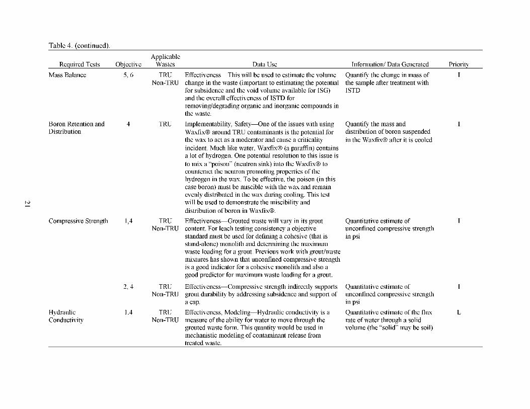
Table 4. (continued). Applicable
Required Tests Objective Wastes Data Use Information/ Data Generated Priority
Non-TRU change in the waste (important to estimating the potential the sample after treatment with for subsidence and the void volume available for ISG) ISTD and the overall effectiveness of ISTD for removing/degra&ng organic and inorganic compounds in the waste.
Waxfix@ around TRU contaminants is the potential for the wax to act as a moderator and cause a criticality incident. Much like water, Waxfix@ (a paraffin) contains a lot of hydrogen. One potential resolution to th~s issue is to mix a “poison” (neutron sink) into the Waxfix@ to counteract the neutron promoting properties of the hydrogen in the wax. To be effective, the poison (in this case boron) must be miscible with the wax and remain evenly distributed in the wax during cooling. This test will be used to demonstrate the miscibility and distribution of boron in Waxfix@.
Mass Balance 5,6 TRU Effectiveness-This will be used to estimate the volume Quantify the change in mass of I
Boron Retention and 4 TRU Implementability, Safety-One of the issues with using Quantify the mass and I Distribution distribution of boron suspended
in the Waxfix@ after it is cooled
E
Compressive Strength 1,4 TRU Effectiveness-Grouted waste will vary in its grout Quantitative estimate of Non-TRU content. For leach testing consistency a objective
standard must be used for defining a cohesive (that is stand-alone) monolith and determining the maximum waste loading for a grout. Previous work with groutlwaste mixtures has shown that unconfined compressive strength is a good indicator for a cohesive monolith and also a good predictor for maximum waste l o a d q for a grout.
unconfined compressive strength in psi
I
2,4 TRU Effectiveness-Compressive strength indnectly supports Quantitative estimate of I Non-TRU grout durability by addressing subsidence and support of
a cap. in psi
Non-TRU measure of the ability for water to move through the grouted waste form. This quantity would be used in mechanistic modeling of contaminant release from treated waste.
unconfined compressive strength
Hydraulic 1,4 TRU Effectiveness, Modeling-Hydraulic conductivity is a Quantitative estimate of the flux L Conductivity rate of water through a solid
volume (the “solid’ may be soil)
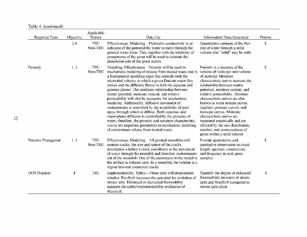
Table 4. (continued).
Porosity
Applicable Required Tests Objective Wastes Data Use Information/ Data Generated Priority
2,4 TRU Effectiveness, Modeling-Hydraulic conductivity is an Quantitative estimate of the flux L Non-TRU indicator of the potential for water to move through the
grouted waste form. This, together with the solubility of components of the grout will be used to estimate the dissolution rate of the grout matrix.
Non-TRU mechanistic modeling of release from treated waste and is volume of voids per unit volume a fundamental modeling input that controls both the of material. Moisture interstitial velocity at which a given Darcian water flux characteristic curves measure the moves and the dffusive fluxes in both the aqueous and relationship between matric gaseous phases. The nonlinear relationship between potential, moisture content, and matric potential, moisture content, and relative relative permeability. Moisture permeability will also be necessary for mechanistic characteristic curves are also modeling. Additionally, diffusive movement of known as water release curves, contaminants is controlled by the availability of pore capillary pressure curves, and space through which to dffuse. Both aqueous- and theta-psi curves. Moisture vapor-phase dffusion is controlled by the presence of characteristic curves are water; therefore, the porosity and moisture characteristic measured empirically and are curves are important parameters in mechanistic modeling affected by the size distribution, of contaminant release from treated waste. number, and connectedness of
pores within a solid volume
Non-TRU contain cracks; the size and nature of the cracks qualitative observation on crack determines whether a crack contributes to the movement length, aperture, connectivity, of water through the monolith and therefore contaminants and frequency in neat grout out of the monolith. One of the parameters in the model is samples the surface to volume ratio. In a monolith, the volume is a region between connected cracks.
whether Waxfix@ increases the potential for oxidation of flammability mixtures of nitrate nitrate salts. Enhanced or decreased flammability salts and Waxfix@ compared to supports the safetyhmplementability evaluation of nitrate salts alone Waxfix@.
rate of water through a solid volume (the “solid’ may be soil)
1,2 TRU Modeling, Effectiveness-Porosity will be used in Porosity is a measure of the L
Fracture Propagation 1,2 TRU Effectiveness, Modeling-All grouted monoliths will Provide quantitative and
4 TRU Implementability, Safety-These tests will demonstrate Quantify the degree of enhanced I
L
DOT Oxidizer

Table 4. (continued). Applicable
Required Tests Objective Wastes Data Use Microencapsulation L 4 TRU Effectiveness-This test with Waxfix@ completes a set
of tests that were previously completed for the other three grouts. This test provides quantitative insight on the mechanism of release of organic surrounded by grout.
Pu Aerosolization
Leachability (Radionuclides, Inorganics and Organics)
Macroencapsulation L 4 TRU Effectiveness-This test with Waxfix@ completes a set of tests that were previously completed for the other three grouts. This test provides quantitative insight on the mechanism of release of organic surrounded by grout.
Non-TRU safety/implementation issue is the generation of hydrogen from the radolysis of hydrogen containing molecules in the grout from the radation emitted by the waste when it is mixed with the grout. Waxfix@ is a paraffin-based grout and therefore contains a high percentage of hydrogen. This test will mix a known amount of radionuclides with a sample of Waxfix@ grout and measure the generation rate of hydrogen compared to a sample of Waxfix@ grout without radionuclides.
contaminants from grout returns which have cured (are dry) is a potential safety concern. The data from th~s test will be used to estimate the potential and amount of TRU contaminants released into the air from grout that comes to the surface as a part of the jet grouting process.
1 TRU Modeling, Effectiveness-The leach index will be Non-TRU converted into a dffusion coefficient for each
Pad A contaminant which will be used in the modeling to estimate the rate of contaminant release from the treated waste over time.
Hydrogen Generation 4 TRU Implementability, Safety-One potential
3 TRU Implementability, Safety-Aerosolization of TRU
Information/ Data Generated Priority Quantitative estimate of the I release rate of VOCs from a waste/grout configuration
Quantitative estimate of the I release rate of VOCs from a waste/grout configuration
Quantitative estimate of the I generation rate of hydrogen
Quantitative estimate of I aerosolization rate during mixing of grout and waste
For ANS 16.1 provide a quantitative estimate of the diffusion-based leach rate of contaminants (rad, inorganic, organic). For Kd provide a quantative estimate of the partition coefficient between waste form and simulated groundwater
I
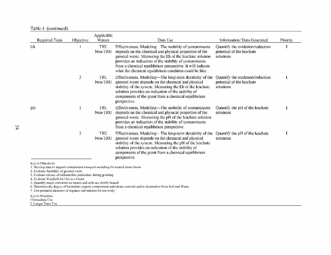
Table 4. (continued). Applicable
Required Tests Objective Wastes Data Use Information/ Data Generated Priority Eh
PH
1 TRU Non-TRU
2 TRU Non-TRU
1 TRU Non-TRU
2 TRU Non-TRU
Effectiveness, Modeling-The mobility of contaminants Quantify the oxidatiodreduction I depends on the chemical and physical properties of the grouted waste. Measuring the Eh of the leachate solution provides an indcation of the stability of contaminants from a chemical equilibrium perspective. It will indcate what the chemical equilibrium condition could be like.
grouted waste depends on the chemical and physical stability of the system. Measuring the Eh of the leachate solution provides an indcation of the stability of components of the grout from a chemical equilibrium perspective. Effectiveness, Modeling-The mobility of contaminants depends on the chemical and physical properties of the grouted waste. Measuring the pH of the leachate solution provides an indcation of the stability of contaminants from a chemical equilibrium perspective. Effectiveness, Modeling-The long-term durability of the Quantify the pH of the leachate grouted waste depends on the chemical and physical solutions stability of the system. Measuring the pH of the leachate solution provides an indcation of the stability of components of the grout from a chemical equilibrium perspective.
potential of the leachate solutions
Effectiveness, Modeling-The long-term durability of the Quantify the oxidatiodreduction I potential of the leachate solutions
Quantify the pH of the leachate solutions
I
Key to Objectives 1. Develop data to support contaminant transport modeling for treated waste forms 2. Evaluate durability of grouted waste 3. Evaluate release of radionuclide particulate during grouting 4. Evaluate WaxfixB for Use as a Grout 5. Quantify major emissions as wastes and soils are slowly heated 6 . Determine the degree of hazardous organic contaminant and nitrate removal and/or destruction from Soil and Waste 7. Test potential mixtures of organics and nitrates for reactivity
Key to Priorities: I Immediate Use L Longer Term Use
I
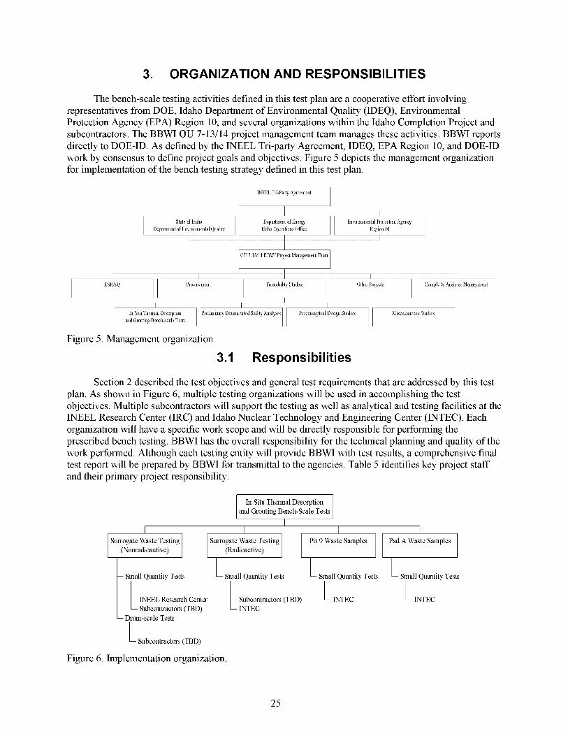
3. ORGAN IZATlON AND RESPONS I BI LIT1 ES
The bench-scale testing activities defined in this test plan are a cooperative effort involving representatives from DOE, Idaho Department of Environmental Quality (IDEQ), Environmental Protection Agency (EPA) Region 10, and several organizations within the Idaho Completion Project and subcontractors. The BBWI OU 7-13/14 project management team manages these activities. BBWI reports directly to DOE-ID. As defined by the INEEL Tri-party Agreement, IDEQ, EPA Region 10, and DOE-ID work by consensus to define project goals and objectives. Figure 5 depicts the management organization for implementation of the bench testing strategy defined in this test plan.
WEEL Tri-Party Agreement
Department ofEnergy Environmental Protection Agency Department of Environmental Quality Idaho Operations Office
~ OU 7-13/14 BBWIProject Management Team
i s x * y ~ ? ~ F ~ T ~ F Sample & Analysis Management
Figure 5 . Management organization.
3.1 Res pons i bi I ities
Section 2 described the test objectives and general test requirements that are addressed by this test plan. As shown in Figure 6, multiple testing organizations will be used in accomplishing the test objectives. Multiple subcontractors will support the testing as well as analytical and testing facilities at the INEEL Research Center (IRC) and Idaho Nuclear Technology and Engineering Center (INTEC). Each organization will have a specific work scope and will be directly responsible for performing the prescribed bench testing. BBWI has the overall responsibility for the technical planning and quality of the work performed. Although each testing entity will provide BBWI with test results, a comprehensive final test report will be prepared by BBWI for transmittal to the agencies. Table 5 identifies key project staff and their primary project responsibility.
In Situ Thermal Desorption
Surrogate Waste Testing (Nonradioactive)
Surrogate Waste Testing
- Small Quantity Tests Small Quantity Tests
INEEL Research Center INTEC INTEC c Subcontractors (TBD) - Drum-scale Tests
Subcontractors (TBD)
Figure 6. Implementation organization.
25

Table 5. Key project staff and responsibility. Project Responsibility Team Member
Agencies DOE WAG 7 Project Manager EPA Region 10 WAG 7 Project Manager IDEQ WAG 7 Project Manager
Project Director John Schaffer
WAG 7 OU 13/14 Project Manager Frank Webber Treatability Studies Project Manager Brandt Meagher Bench-scale Testing Technical Lead Gretchen Matthern Grouting Principal Investigators Guy Loomis
Neal Yancey
Jeff Snook &ck Poeton Ted LivieratodDaryl Koch
BBWI
ISTD Principal Investigators Peter Shaw Dave Nickelson
Sample and Analysis Management INTEC Ken Brewer Health and Safety Kelly Wooley Quality Charlie Chebul Waste Generator Services Jeff Messaros Environmental Brent Burton Procurement Alan French
Testing To be determined Analytical To be determined Material Suppliers To be determined
To be determined
Subcontractors
3.2 Training
Training requirements are established by each testing organization and are specific to the testing facility and identified hazards posed by testing. Before initiating testing at INEEL facilities, hazard checklists and mitigation plans will be prepared as prescribed by INEEL Management Control Procedure (MCP)-357 1, Independent Huzurd Review. Specific training requirements not already addressed by the facility’s authorization basis will be identified through the Independent Hazard Review. Training records for BBWI testing personnel will be reviewed to ensure that job-specific training requirements have been addressed and are up to date.
Subcontracted organizations will be required to verify that subcontractor personnel are adequately trained to conduct the testing work scope by providing related training records and certifications to the BBWI Procurement Vendor Data Coordinator. Selected vendors must be able to demonstrate compliance with all core hnctions of the DOE Integrated Safety Management System.
26
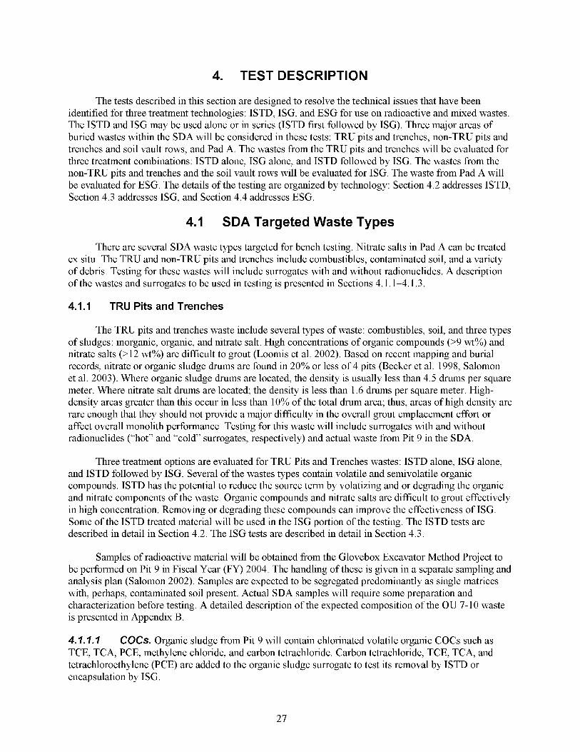
4. TEST DESCRIPTION
The tests described in this section are designed to resolve the technical issues that have been identified for three treatment technologies: ISTD, ISG, and ESG for use on radioactive and mixed wastes. The ISTD and ISG may be used alone or in series (ISTD first followed by ISG). Three major areas of buried wastes within the SDA will be considered in these tests: TRU pits and trenches, non-TRU pits and trenches and soil vault rows, and Pad A. The wastes from the TRU pits and trenches will be evaluated for three treatment combinations: ISTD alone, ISG alone, and ISTD followed by ISG. The wastes from the non-TRU pits and trenches and the soil vault rows will be evaluated for ISG. The waste from Pad A will be evaluated for ESG. The details of the testing are organized by technology: Section 4.2 addresses ISTD, Section 4.3 addresses ISG, and Section 4.4 addresses ESG.
4.1 SDA Targeted Waste Types
There are several SDA waste types targeted for bench testing. Nitrate salts in Pad A can be treated ex situ. The TRU and non-TRU pits and trenches include combustibles, contaminated soil, and a variety of debris. Testing for these wastes will include surrogates with and without radionuclides. A description of the wastes and surrogates to be used in testing is presented in Sections 4.1.1-4.1.3.
4.1.1 TRU Pits and Trenches
The TRU pits and trenches waste include several types of waste: combustibles, soil, and three types of sludges: inorganic, organic, and nitrate salt. High concentrations of organic compounds (>9 wt%) and nitrate salts (>12 wt%) are difficult to grout (Loomis et al. 2002). Based on recent mapping and burial records, nitrate or organic sludge drums are found in 20% or less of 4 pits (Becker et al. 1998, Salomon et al. 2003). Where organic sludge drums are located, the density is usually less than 4.5 drums per square meter. Where nitrate salt drums are located; the density is less than 1.6 drums per square meter. High- density areas greater than this occur in less than 10% of the total drum area; thus, areas of high density are rare enough that they should not provide a major difficulty in the overall grout emplacement effort or affect overall monolith performance. Testing for this waste will include surrogates with and without radionuclides (“hot” and “cold’ surrogates, respectively) and actual waste from Pit 9 in the SDA.
Three treatment options are evaluated for TRU Pits and Trenches wastes: ISTD alone, ISG alone, and ISTD followed by ISG. Several of the wastes types contain volatile and semivolatile organic compounds. ISTD has the potential to reduce the source term by volatizing and or degrading the organic and nitrate components of the waste. Organic compounds and nitrate salts are difficult to grout effectively in high concentration. Removing or degrading these compounds can improve the effectiveness of ISG. Some of the ISTD treated material will be used in the ISG portion of the testing. The ISTD tests are described in detail in Section 4.2. The ISG tests are described in detail in Section 4.3.
Samples of radioactive material will be obtained from the Glovebox Excavator Method Project to be performed on Pit 9 in Fiscal Year (FY) 2004. The handling of these is given in a separate sampling and analysis plan (Salomon 2002). Samples are expected to be segregated predominantly as single matrices with, perhaps, contaminated soil present. Actual SDA samples will require some preparation and characterization before testing. A detailed description of the expected composition of the OU 7-10 waste is presented in Appendix B.
4.7.7.7 COCs. Organic sludge from Pit 9 will contain chlorinated volatile organic COCs such as TCE, TCA, PCE, methylene chloride, and carbon tetrachloride. Carbon tetrachloride, TCE, TCA, and tetrachloroethylene (PCE) are added to the organic sludge surrogate to test its removal by ISTD or encapsulation by ISG.
27

4.1.1.2 Surrogates for TRU Pit and Trench Wastes. Simulated waste, soil, and actual SDA samples will be used for the bench- and drum-scale ISTD testing and the ISG testing. Preparation of surrogates (sludges, nitrate salts) is the first step of the bench test. Valuable information, baseline data, and method verification can be obtained when heating spiked soils and waste surrogate matrices such as nitrate salts and sludges.
Inorganic Sludge Surrogate. The simulated inorganic sludge formulation is based on the average composition of inorganic precipitates in the original RFP 741 and 742 sludge (Landman 198 1, Clements 1982) and previous surrogates developed to represent these sludges (Low 1985, Low et al. 1987, Loomis and Low 1988) as shown in Table 6. The inorganic sludge surrogate will contain some RWMC lake-bed soil, other inorganic salts, water with terbium added, and some nitrate salts. The actual RFP wastes are estimated to have contained 40-70 wt% water, to which 10-20 wt% cement was added when the sludge was placed in drums. At 20 wt% cement, the sludge-cement mixture would likely resemble a consolidated rather than an unconsolidated material. To be conservative with respect to evaluating the performance of ISG and ISTD, the amount of water and cement has been minimized to maximize the concentration of inorganic salts and create an unconsolidated material. This approach is consistent with previous testing activities (Low 1985, Low et al. 1987, Loomis and Low 1988).
Table 6. Composition of RFP Series Number 741, 742 Inorganic Sludge surrogate waste for ISTD.
Soil 20” CaC03, 10 Water 20” Portland cement 10
Compound Weight Percentage
Rare-earth tracer CaN03 NaN03,
Na2HP04 7H20 KNo3
2 3 10 5
20
a. INEEL soil contains 15 &YO water.
Organic Sludge Surrogate. A simulated organic sludge will be prepared using the average constituents of the original RFP Series 743 organic sludge as shown in Table 7. Two different estimates of organic sludge compositions have been developed based on several reports (Clements 1982, Vigil 1989, Liekhaus 1991, and Arrenholz and Knight 1991). The earlier 1982 and 1989 assessments gave the approximate organic liquid content of SDA sludges based on sludge preparation and shipping records. The 1991 assessments have been updated, based on the following:
Calculations from recent vapor removal by the organic contamination vadose zone system
Newly found records as RFP sludge preparation areas are decontaminated
0 Recent shallow sampling of organic vapor between waste pits.
28
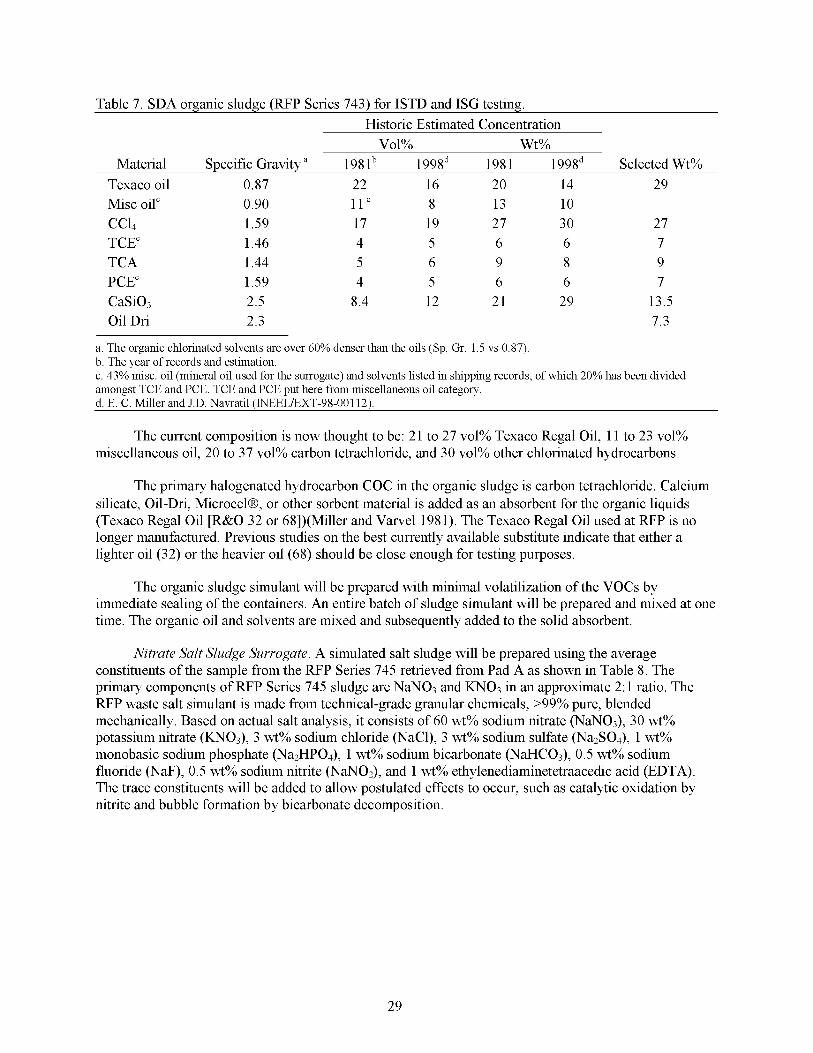
Table 7. SDA organic sludge (RFP Series 743) for ISTD and ISG testing. Historic Estimated Concentration
Vol% Wt% Material Specific Gravity a 1981b 199Sd 1981 199Sd Selected Wt%
Texaco oil 0.87 22 16 20 14 29 Misc oil' 0.90 11' 8 13 10 C c 4 1.59 17 19 27 30 27 TCE' 1.46 4 5 6 6 7 TCA 1.44 5 6 9 8 9 PCE' 1.59 4 5 6 6 7 CaSi03 2.5 8.4 12 21 29 13.5 Oil Dri 2.3 7.3
a. The organic chlorinated solvents are over 60% denser than the oils (Sp. Gr. 1.5 vs 0.87). b. The year of records and estimation. c. 43% misc. oil (mineral oil used for the surrogate) and solvents listed in shpping records, of which 20% has been divided amongst TCE and PCE. TCE and PCE put here from miscellaneous oil category. d. E. C. Miller and J.D. Navratil (INEELEXT-98-00112).
The current composition is now thought to be: 21 to 27 vol% Texaco Regal Oil, 11 to 23 vol% miscellaneous oil, 20 to 37 vol% carbon tetrachloride, and 30 vol% other chlorinated hydrocarbons.
The primary halogenated hydrocarbon COC in the organic sludge is carbon tetrachloride. Calcium silicate, Oil-Dri, MicrocelB, or other sorbent material is added as an absorbent for the organic liquids (Texaco Regal Oil [R&O 32 or 68])(Miller and Varve1 1981). The Texaco Regal Oil used at RFP is no longer manufactured. Previous studies on the best currently available substitute indicate that either a lighter oil (32) or the heavier oil (68) should be close enough for testing purposes.
The organic sludge simulant will be prepared with minimal volatilization of the VOCs by immediate sealing of the containers. An entire batch of sludge simulant will be prepared and mixed at one time. The organic oil and solvents are mixed and subsequently added to the solid absorbent.
Nitrate Salt Sludge Surrogate. A simulated salt sludge will be prepared using the average constituents of the sample from the RFP Series 745 retrieved from Pad A as shown in Table 8 . The primary components of RFP Series 745 sludge are NaN03 and KN03 in an approximate 2: 1 ratio. The RFP waste salt simulant is made from technical-grade granular chemicals, >99% pure, blended mechanically. Based on actual salt analysis, it consists of 60 wt% sodium nitrate (NaN03), 30 wt% potassium nitrate (KN03), 3 wt% sodium chloride (NaCl), 3 wt% sodium sulfate (Na2S04), 1 wt% monobasic sodium phosphate (Na2HP04), 1 wt% sodium bicarbonate (NaHC03), 0.5 wt% sodium fluoride (NaF), 0.5 wt% sodium nitrite (NaN02), and 1 wt% ethylenediaminetetraacedic acid (EDTA). The trace constituents will be added to allow postulated effects to occur, such as catalytic oxidation by nitrite and bubble formation by bicarbonate decomposition.
29
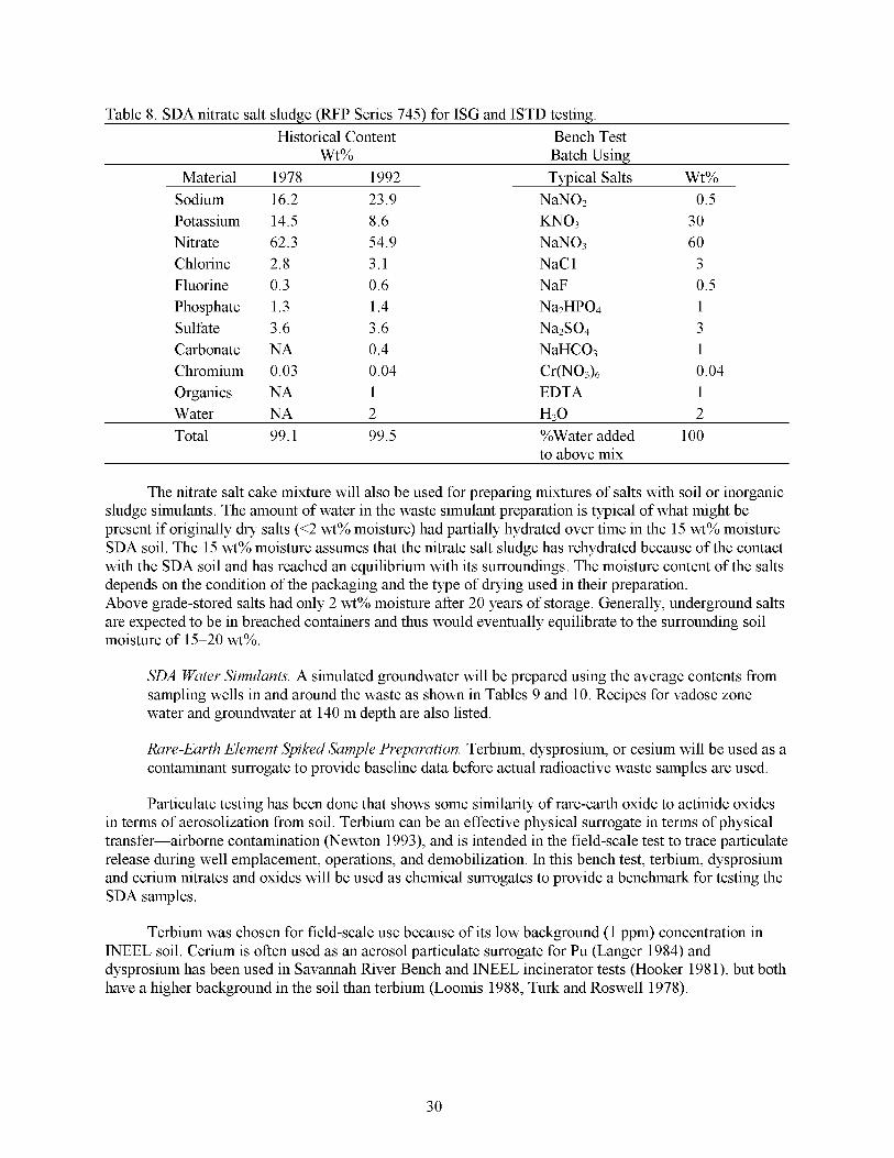
Table 8. SDA nitrate salt sludge (RFP Series 745) for ISG and ISTD testing. Historical Content Bench Test
Wt% Batch Using Material 1978 1992 Typical Salts Wt%
Sodium 16.2 23.9 NaN02 0.5 Potassium 14.5 8.6 KNo3 30 Nitrate 62.3 54.9 NaN03 60 Chlorine 2.8 3.1 NaC 1 3 Fluorine 0.3 0.6 NaF 0.5 Phosphate 1.3 1.4 Na2HP04 1 Sulfate 3.6 3.6 Na2S04 3 Carbonate NA 0.4 NaHC03 1 Chromium 0.03 0.04 cr(No3)6 0.04 Organics NA 1 EDTA 1 Water NA 2 H2O 2 Total 99.1 99.5 %Water added 100
to above mix
The nitrate salt cake mixture will also be used for preparing mixtures of salts with soil or inorganic sludge simulants. The amount of water in the waste simulant preparation is typical of what might be present if originally dry salts (<2 wt% moisture) had partially hydrated over time in the 15 wt% moisture SDA soil. The 15 wt% moisture assumes that the nitrate salt sludge has rehydrated because of the contact with the SDA soil and has reached an equilibrium with its surroundings. The moisture content of the salts depends on the condition of the packaging and the type of drying used in their preparation. Above grade-stored salts had only 2 wt% moisture after 20 years of storage. Generally, underground salts are expected to be in breached containers and thus would eventually equilibrate to the surrounding soil moisture of 15-20 wt%.
SDA Water Simulants. A simulated groundwater will be prepared using the average contents from sampling wells in and around the waste as shown in Tables 9 and 10. Recipes for vadose zone water and groundwater at 140 m depth are also listed.
Rare-Earth Element Spiked Sample Preparation. Terbium, dysprosium, or cesium will be used as a contaminant surrogate to provide baseline data before actual radioactive waste samples are used.
Particulate testing has been done that shows some similarity of rare-earth oxide to actinide oxides in terms of aerosolization from soil. Terbium can be an effective physical surrogate in terms of physical transfer-airborne contamination (Newton 1993), and is intended in the field-scale test to trace particulate release during well emplacement, operations, and demobilization. In this bench test, terbium, dysprosium and cerium nitrates and oxides will be used as chemical surrogates to provide a benchmark for testing the SDA samples.
Terbium was chosen for field-scale use because of its low background (1 ppm) concentration in INEEL soil. Cerium is often used as an aerosol particulate surrogate for Pu (Langer 1984) and dysprosium has been used in Savannah Ever Bench and INEEL incinerator tests (Hooker 198 l), but both have a higher background in the soil than terbium (Loomis 1988, Turk and Roswell 1978).
30
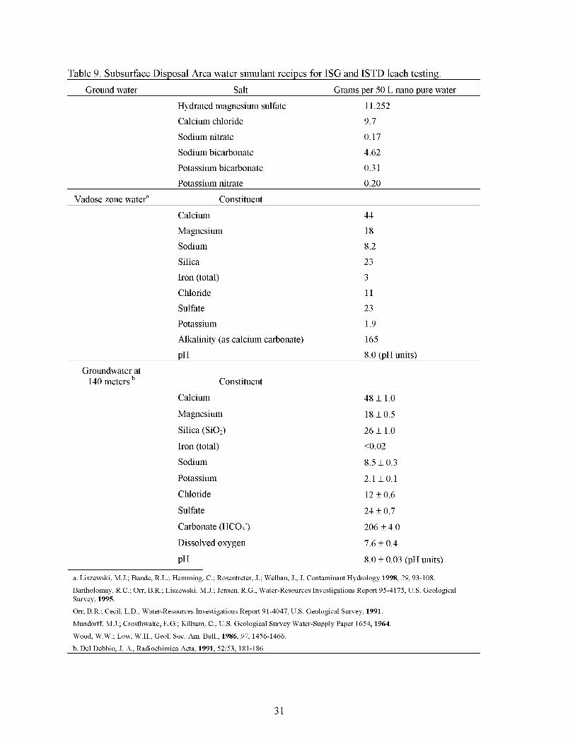
Table 9. Subsurface Disposal Area water simulant recipes for ISG and ISTD leach testing.
Ground water Salt Grams Der 50 L nano pure water Hydrated magnesium sulfate Calcium chloride
11.252 9.7
Sodium nitrate 0.17 Sodium bicarbonate 4.62 Potassium bicarbonate 0.3 I Potassium nitrate 0.20
Vadose zone watera Constituent Calcium 44 Magnesium 18 Sodium Silica Iron (total) Chloride Sulfate
8.2 23 3 11 23
Potassium 1.9 Alkalinity (as calcium carbonate) 165 PH 8.0 (pH units)
Groundwater at 140 meters Constituent
Calcium 48 f 1.0 Magnesium
Silica (Si02)
Iron (total) Sodium
18 f 0.5
26 f 1.0 <o .02
8.5 f 0.3
Potassium 2.1 f O . l
Chloride 12 f 0.6
Sulfate 24 f 0.7
Carbonate (HCO?.) 206 f 4.0
Dissolved oxygen 7.6 f 0.4
PH 8.0 f 0.03 (pH units)
a. Liszewski, M.J.; Bunde, R.L.; Hemming, C.; Rosentreter, J.; Welhan, J., J. Contaminant Hydrology 1998, 29, 93-108.
Bartholomay, R.C.; Orr, B.R.; Liszewski, M.J.; Jensen, R.G., Water-Resources Investigations Report 95-4175, U.S. Geological Survey, 1995.
Orr, B.R.; Cecil, L.D., Water-Resources Investigations Report 91-4047, U.S. Geological Survey, 1991.
Mundorff, M.J.; Crosthwaite, E.G.; Kilburn, C., U.S. Geological Survey Water-Supply Paper 1654, 1964.
Wood, W.W.; Low, W.H., Geol. SOC. Am. Bull., 1986,97, 1456-1466.
b. Del Debbio. J. A,. Radiochimica Acta. 1991. 52/53. 181-186
31
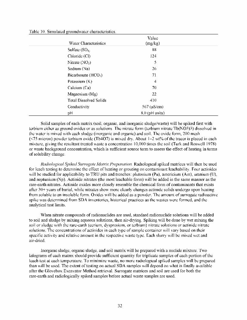
Table 10. Simulated groundwater characteristics Value
Water Characteristics (mgk3) Sulfate (SO,, 88
Nitrate (NO3) 5 Chloride (Cl) 124
Sodium (Na) 26 Bicarbonate (HC03) 71 Potassium (K) 4
Magnesium (Mg) 22 Calcium (Ca) 70
Total Dissolved Solids 410 Conductivity 567 (pS/cm) DH 8.0 (DH units)
Solid samples of each matrix (soil, organic, and inorganic sludge/waste) will be spiked first with terbium either as ground oxides or as solutions. The nitrate form (terbium nitrate Tb(N03)3) dissolved in the water is mixed with each sludge (inorganic and organic) and soil. The oxide form, 200 mesh (<75 micron) powder terbium oxide (Tb407) is mixed dry. About 1-2 wt% of the tracer is placed in each mixture, giving the resultant treated waste a concentration 10,000 times the soil (Turk and Roswell 1978) or waste background concentration, which is sufficient source term to assess the effect of heating in terms of solubility change.
Radiological Spiked Surrogate Matrix Preparation. Radiological spiked matrices will then be used for leach testing to determine the effect of heating or grouting on contaminant leachability. Four actinides will be studied for applicability to TRU pits and trenches: plutonium (Pu), americium (Am), uranium (U), and neptunium (Np). Actinide nitrates (the most leachable form) will be added in the same manner as the rare-earth nitrates. Actinide oxides more closely resemble the chemical form of contaminants that exists after 30+ years of burial, while nitrates show more clearly changes actinide solids undergo upon heating from soluble to an insoluble form. Oxides will be added as a powder. The amount of surrogate radioactive spike was determined from SDA inventories, historical practices as the wastes were formed, and the analytical test limits.
When nitrate compounds of radionuclides are used, standard radionuclide solutions will be added to soil and sludge by mixing aqueous solutions, then air-drying. Spiking will be done by wet mixing the soil or sludge with the rare-earth (cerium, dysprosium, or terbium) nitrate solutions or actinide nitrate solutions. The concentrations of actinides in each type of sample container will vary based on their specific activity and relative amount in the respective waste type. Each slurry will be mixed wet and air-dried.
Inorganic sludge, organic sludge, and soil matrix will be prepared with a nuclide mixture. Two kilograms of each matrix should provide sufficient quantity for triplicate samples of each portion of the leach test at each temperature. To minimize waste, no more radiological spiked samples will be prepared than will be used. The extent of testing on actual SDA samples will depend on what is finally available after the Glovebox Excavator Method retrieval. Surrogate matrices and soil are used for both the rare-earth and radiologically spiked samples before actual waste samples are used.
32
Debris Surrogate. Debris surrogate will consist of combustible (such as paper, rags, gloves, cardboard, PPE, and plastic) and noncombustible materials (such as cement, metal, asphalt, soil, and glass). The exact proportions of the materials will be determined before testing. Debris surrogates are highly variable, as the waste was not created in a “factorylike process“ as the sludges were. Any mixture of common paper trash is suitable for this study. For the combustible debris surrogate we will be using the following: rags 40 w/o; paper towels 40 w/o; polyethylene 10 w/o; ABS plastic 5 w/o; and PVC plastic 5 w/o.
4.1.2 Non-TRU Pits and Trenches, and Soil Vault Rows Waste Surrogate
In situ grouting is also being evaluated for treatment of non-TRU pits and trenches, and soil vault rows waste. Pits 7, 8, and 13-16, trenches 11-58, and soil vault rows 1-20 contain non-TRU waste. This waste consists mainly of contaminated debris and soil. No actual non-TRU waste from the SDA will be used in these tests. Testing will be done using hot surrogates composed of soil spiked with radionuclides.
4.1.2.1 COCs. Tc-99, C-14,I-129, andNb-94
4.1.2.2 Non-TRU wastes have been generated from a variety of processes. Contaminated soil will be used as the waste matrix, since debris surrogates are only practical in field-scale testing where they can be properly scaled. Specific wastes such as the beryllium blocks and the remote-handled waste that was disposed of in cribs, vessels, and tanks. will not be simulated in this test plan. Wastes that will be simulated (actual wastes will also be used in some cases) in this test plan include: organic sludge, inorganic sludge, nitrate salt sludge, and debris waste from TRU Pits and Trenches, contaminated soil from non-TRU pits and trenches, and nitrate salts from Pad A.
Surrogates for non-TRU Pits and Trenches and Soil Vaults Rows Wastes.
Hot Surrogate Preparation. Tc-99, C-14, Nb-94, and 1-129 will be used to make surrogates.
INEEL soil will be spiked first with Nb either as ground oxides or as solutions. The nitrate form, niobium nitrate (NbN05) dissolved in the water is mixed with soil. The oxide form, 200 mesh (<75 micron) powder Niobium oxide (Nbz05) is mixed dry. About 1-2 wt% of the tracer is placed in each mixture, giving the resultant treated waste a concentration 10,000 times the soil or waste background concentration and sufficient source term to access the effect of grouting in terms of solubility.
Technetium nitrate (and C-14 as carbonate or in steel) will be deposited in the same manner as Nb-94. Technetium oxide or Technate salts more closely resemble the chemical form of the metal that exists after 30+ years of burial, while nitrates show more clearly the effect grouts have in preventing leaching of soluble species or changing soluble to an insoluble form. Actual SDA non-TRU waste will not be provided so the proper physical and chemical state that determines leaching and the proper matrix to test will have to be simulated. The amount of surrogate radioactive spike is based on determined SDA inventories, historical practices as non-TRU waste has been generated, and analytical test limits.
4.1.3 Pad A Waste
Ex situ grouting is being evaluated for treatment of Pad A waste.
4.1.3.1 60 wt% sodium nitrate flakes with about 400 ppm soluble chromate (much as Cr+6) and 180 pCi/g uranium as the primary hazardous and radioactive components. Samples from a retrieved Pad A drum have been obtained and will be used for this mixing study. The objective of this study is to test encapsulation agents to see if uranium and nitrate will be immobilized.
Composition of Pad A Waste. Pad A salts consist of 30 wt% potassium nitrate and
33
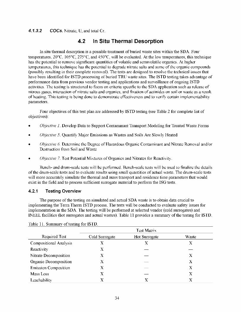
4.7.3.2 COCs. Nitrate, U, and total Cr
4.2 In Situ Thermal Desorption
In situ thermal desorption is a possible treatment of buried waste sites within the SDA. Four temperatures, 20"C, 105"C, 275"C, and 450"C, will be evaluated. At the low temperatures, this technique has the potential to remove significant quantities of volatile and semivolatile organics. At higher temperatures, this technique has the potential to degrade nitrate salts and some of the organic compounds (possibly resulting in their complete removal). The tests are designed to resolve the technical issues that have been identified for ISTD processing of buried TRU waste sites. The ISTD testing takes advantage of performance data from previous vendor testing and applications and surveillance of ongoing ISTD activities. The testing is structured to focus on criteria specific to the SDA application such as release of nitrous gases, interaction of nitrate salts and organics, and fixation of actinides on soil or waste as a result of heating. This testing is being done to demonstrate effectiveness and to verify certain implementability parameters.
Four objectives of this test plan are addressed by ISTD testing (see Table 2 for complete list of objectives) :
Objective 1. Develop Data to Support Contaminant Transport Modeling for Treated Waste Forms
0 Objective 5. Quantify Major Emissions as Wastes and Soils Are Slowly Heated
Objective 6. Determine the Degree of Hazardous Organic Contaminant and Nitrate Removal and/or Destruction from Soil and Waste
0 Objective 7. Test Potential Mixtures of Organics and Nitrates for Reactivity.
Bench- and drum-scale tests will be performed. Bench-scale tests will be used to finalize the details of the drum-scale tests and to evaluate results using small quantities of actual waste. The drum-scale tests will more accurately simulate the thermal and mass transport and residence time parameters that would exist in the field and to process sufficient surrogate material to perform the ISG tests.
4.2.1 Testing Overview
The purpose of the testing on simulated and actual SDA waste is to obtain data crucial to implementing the Terra Therm ISTD process. The tests will be conducted to evaluate safety issues for implementation in the SDA. The testing will be performed at selected vendor (cold surrogates) and INEEL facilities (hot surrogates and actual wastes). Table 11 provides a summary of the testing for ISTD.
Table 1 1. Summary of testing for ISTD. Test Matrix
Required Test Cold Surrogate Hot Surrogate Waste Compositional Analysis X X X Reactivity X - -
Nitrate Decomposition X X Organic Decomposition X X Emission Composition X X
Leachability X X X
-
-
-
- Mass Loss X X
34

The basic experimental sequence is as follows:
1. Waste and contaminant surrogates are prepared
2. Samples are heated
3. Off-gas monitoring and reactivity testing are performed during the heating process
4. Leach and residue testing is performed on treated samples
5. Ensure the final form of the material is suitable for the grouts that are proposed for use.
This experimental design is as simple and direct as possible to manage costs, minimize wastes (as radiological materials will be used), and address specific primary effectiveness and safety objectives.
For all matrices, qualitative observation will be made describing the physical characteristics of the waste types as they are heated. For surrogate matrices, quantitative data to be collected include off-gas concentrations, observed reactivity of nitrates with organics, decomposition of nitrates and organics, leachability of simulated COCs, and nitrate and organic chloride concentrations on treated wastes.
For actual Pit 9 waste, quantitative data to be collected include off-gas concentrations, decomposition of nitrates and organics, COC leach ability, and COC and other waste constituent concentrations. Radiological laboratories will be required to heat and test leaching after heating of any radiological spiked or waste samples from Pit 9.
4.2.2 General Test Procedures
Each matrix (organic and inorganic sludge waste and soil for leachability; organic sludge and nitrate salts for removal) will be tested at four temperature ranges as shown in Table 12. The test temperatures were chosen both as potential operational goals and because of critical changes that occur in some of the waste matrices at that temperature.
Table 12. Basis for temperatures for leachability, off-gas, and removal decomposition studies.
"C "C Reason Comments Target Range
20 15 to 25 Control Ambient temperature
105 90 to 120 Boiling point of water Removal of water, organic chloride solvents
275 250 to 300 Nitrate salt eutectic melting Melting of salts some pyrolysis/ point decomposition of organics and plastics,
carbonate removal
450 450 to 500 Minimum average final Decomposition of nitrates, Reactivity zone temperature
For lab-scale tests, each sample will be placed in the tube hrnace, brought to the stated temperature, and held there for 24 hours. This laboratory condition is for the sake of testing at specific minimum target temperatures. Field temperatures will gradually rise throughout the waste. Specific areas could see a much faster or slower rate of temperature increase. In situ thermal desorption can only establish a minimum and maximum target temperature. The minimum is usually found at a distance one half the well spacing and a maximum temperature is adjacent to a heater well, approaching the
35

temperature of the heating elements. The waste will be brought to at least the minimum target temperature. In the field, most of the waste will be at this temperature for much longer than a day because the process is estimated to take at least 2 months.
After heating, samples will be allowed to cool. Mass loss and leachability will be determined. While the temperature is raised, the off-gas composition and concentrations will be measured and reactivity examined. The sample is allowed to cool to ambient for all leach measurements. The primary reason is this case simulates the condition of the waste after ISTD has been employed and water has slowly returned to the dry site. Secondarily, the measurements must be comparable to the before-heating leach case. Thirdly, there is no leaching at raised temperature in underground waste. The ISTD process off-gas system is not moved until underground off-gas products (generally CO, C02) return to ambient levels. The spacing for the next installation of the ISTD equipment is based on the requirement that all waste be raised to at least a minimum temperature to achieve effective treatment. Off-gas composition, rather than temperature, will be used to monitor the cessation of ISTD-induced reactions.
In past ISTD field experience with soils contaminated with organics, vapors exiting the off-gas treatment system have contained concentrations of carbon dioxide (less than 2.0%), carbon monoxide (less than 100 ppm), low total hydrocarbon levels (less than 100 ppm), and water vapor. After the water is removed, the levels of total hydrocarbon decrease as co-distillation ceases and pyrolysis and combustion begin. As organic material pyrolizes, a greater amount of carbon monoxide is encountered.
The amount of water removed from INEEL test soil or sludges will be determined by weighing the sample and comparing to the weight after raising the temperature to 105°C. This is similar to the weight-loss-upon-heating standard method for water content. In the organic sludge, this will include the weight of volatile organic chlorides removed. The weight loss at other temperatures will be measured by comparing before and after weights. Required precision is *15 wt% on replicate samples. Water may be added to the surrogate waste form, though the water is mainly measured when soil is part of the surrogate mixture. Weight loss of both water and organics requires off-gas measurements coupled with calculation. Water can also be collected on silica gel and its weight determined directly.
4.2.3 Required Test-Compositional Analysis
A compositional analysis of Pit 9 wastes, sludge surrogates, and INEEL soil will be done before and after ISTD treatment to support mass balance calculations and leach testing. Table 13 presents the analyses to be performed.
4.2.4 Required Test-Reactivity
All of the previous remediations using ISTD have been on contaminated soil sites (Vinegar, Stegemeier, Sheldon 1997). There is no field information on the reactivity and off-gas effects of slowly heating debris and drummed containers of nitrate salts, such as RFP nitrate salts buried in the SDA with combustible debris type waste or organic sludge material.
Though corrosion is expected to have affected the integrity of most of the drummed waste, corrosion may not have removed the drum from consideration as a mixing barrier. Examination of retrieved drums has shown that plastic bags may remain intact, providing some degree of barrier to mixing. In situ thermal desorption will be applied before jet grouting, so the primary mode for mixing will be subsidence before or during ISTD treatment. The subsidence is not expected to result in a high degree of mixing between the nitrate salts and other materials in the buried waste; however, testing will be done with mixtures of nitrate salts and other materials in the buried waste to determine outcome if mixing did occur.
36
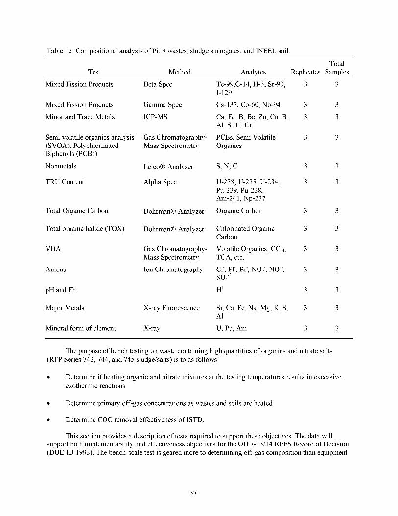
Table 13. Compositional analvsis of Pit 9 wastes. sludge surrogates. and INEEL soil.
Total Test Method Analytes Replicates Samples
Mixed Fission Products Beta Spec Tc-99,C-14, H-3, Sr-90, 3 3
Mixed Fission Products Gamma Spec CS-137, CO-60, Nb-94 3 3
Minor and Trace Metals ICP-MS Ca, Fe, B, Be, Zn, Cu, B, 3 3
Semi volatile organics analysis Gas Chromatography- PCBs, Semi Volatile 3 3
1-129
Al, S, Ti, Cr
(SVOA), Polychlorinated Mass Spectrometry Organics Biphenyls (PCBs)
Nonmetals LeicoB Analyzer s, N, c 3 3
TRU Content Alpha Spec U-238, U-235, U-234, 3 3 PU-239, PU-238, Am-241, Np-237
Total Organic Carbon DohrmanB Analyzer Organic Carbon 3 3
Total organic halide (TOX) DohrmanB Analyzer Chlorinated Organic 3 3 Carbon
VOA
Anions
Gas Chromatography- Volatile Organics, CC4, 3 3
Ion Chromatography Cl-, Fl-, Br-, NO;, NOs-, 3 3
Mass Spectrometry TCA, etc.
soi2 pH and Eh H+ 3 3
Major Metals X-ray Fluorescence Si, Ca, Fe, Na, Mg, K, S, 3 3
Mineral form of element X-ray U, Pu, Am 3 3
A1
The purpose of bench testing on waste containing high quantities of organics and nitrate salts (RFP Series 743, 744, and 745 sludge/salts) is to as follows:
Determine if heating organic and nitrate mixtures at the testing temperatures results in excessive exothermic reactions
0 Determine primary off-gas concentrations as wastes and soils are heated
0 Determine COC removal effectiveness of ISTD.
This section provides a description of tests required to support these objectives. The data will support both implementability and effectiveness objectives for the OU 7-13/14 RI/FS Record of Decision (DOE-ID 1993). The bench-scale test is geared more to determining off-gas composition than equipment
37
that would be used in a large-scale, continuously running system; however, information is gathered that would support off-gas-treatment system selection or design will be included in the final report.
Reactive mixtures of nitrate and organic material currently existing in the SDA are extremely unlikely. Nitrates are always packaged in discrete drums, as are organics (both debris and sludges). No environmental mixing mechanism combines and intimately mixes these discrete waste streams. Furthermore, any mixing that might occur underground would, by definition, involve significant dilution with surrounding soil, water, and other waste. Less than 1% of organic sludge drums and nitrate drums are estimated to be co-located at a high density (4-drums/ square meter or greater). Nitrate salts do not react with organic sludges even when a controlled drum-scale mixture is prepared and heated. The only reactive carbon sources that exist in RWMC are graphite and paper debris. The former is much rarer than organic sludges. Graphite is usually found as chunks packed in discrete drums with no waste-driven internal-corrosion mechanism. Debris drums are low-density carbon sources with even less likelihood of mixing or flowing than a granular sludge or oily liquid (Becker et al. 1998, Clements 1982, Clements & Kudera 1985).
The ISTD process can effectively destroy the nitrate salts as potential oxidizers at temperatures above 3 10°C. Reactivity studies have been done on surrogate and actual salts (Heiser 1999). Heating past the eutectic melting point of the salts (2 10-250°C) to decomposition (270-3 10°C) effectively destroys sodium nitrate and potassium nitrate, which are potential oxidizers; however, if sufficient nitrates are present in intimate contact with finely divided reducing material such as carbon, reactions may be induced before the decomposition is complete.
The RFP nitrate salt sludge surrogate and organic material (organic sludge and combustible debris) will be used alone and in mixtures. Organic material will consist of graphite, oil, or charred combustibles similar to that tested previously (Dick 2001; INEEL 2000). Nitrate salt sludge and organic sludge surrogate mixtures will be mixed intimately and thoroughly. This will provide a definite upper boundary (worst case) in purity, physical form, and degree of mixing. The granulated nitrate salt sludge and organic sludge will also be tested with the inert ingredients (soil) present.
Reactivity measurement will be performed to determine if uncontrolled reactions occur when heating SDA wastes as follows:
Instrumental measurements using differential scanning calorimetry (DSC) analysis
0 Drum-scale 5-55 gal reactivity "cook offs."
4.2.4.7 reactivity, temperature of reaction, and magnitude of reaction during heating. The DSC is a small-scale measurement (0.02 to 0.1 g) performed on a bench-top laboratory instrument. The DSC gives a graphical output (see Figure 7 for an example) of any exotherms of reactivity as the sample is heated. The outputs are the time, temperature, and extent of the reactivity as the sample heats. A variety of powdered chemical mixtures can be easily tested and results generally correlate with large-scale reactivity.
Differential Scanning Calorimetry. Differential scanning calorimetry measures
For testing, a nitrate and carbon sample (graphite, paper char, oil) will be ground, weighed, and added to the platinum boat. The mixture is heated slowly at a prescribed rate such as l"C/minute. The heat absorbed (in the case of endothermic-nitrate decomposition or organic pyrolysis) or given off (in the case of exothermic-organic oxidation) is obtained by comparing these results to the boat containing no sample or a reference sample. At 450"C, nitrate is completely decomposed, any nitrate organic reactivity has occurred (depending on mixture, sample weight and heating rate), and the measurement is then
38

terminated. Exotherms after the nitrate mix is melted (approximately 220°C) are noted and compared to previous nitrate salt DSC runs.
Differential scanning calorimetry has been performed on surrogate and actual RFP nitrate salts with machine oil, paraffin, polystyrene, polyethylene graphite, or cellulose. Cellulose and alkali nitrate salts are the most reactive with a reactive exotherm near the decomposition temperature of 320°C. The nitrate salt graphite mixtures also react but at a much higher temperature above 400°C. Both of these measurements were confirmed by larger scale reactivity tests of cellulose or graphitehitrate mixtures. None of the other organichitrate mixtures showed exotherms. This was confirmed by larger-scale reactivity tests of oil at various concentrations. Differential scanning calorimetry of the actual RFP salts did show slight exotherms from 400°C to 500°C possibly from the 1% organic they contain. Further testing will be performed to support the safety assessment (Dick 1999).
Figure 7 shows an actual DSC scan from a stoichiometric (87% nitrate, 13% carbon) mixture of graphite and actual RFP salts (ITW 1999). The calorimetry scan shows the melting point (endotherm) eutectic of the sodium nitrate (250°C) and potassium nitrate (210°C). The reactivity (exotherm) of the graphite nitrate reaction above 400°C that was seen in the large-scale reactivity tests (Dick 2000) is
File Name: GRAP-01 DO0 Temp Program Sample Name: Pad A Salt/Graphite 87/13 Weigk 21,8l[mg] tW&l [CI [min]
Rate Hold Temp Hold Tim
Cell: Platinum 10.0 500.0 0.0 DSC Atmosphere: Nitrogen
mW/mg
f-
I
-1.8 d
Figure 7. DSC scan of RFP salts and graphite.
39
The data from both the DSC lab-scale and larger bench-scale heating will help to determine that ISTD heating will not cause any excessive reactivity if nitrate salts come in contact with some organics, are mixed, and heated. The bench-test results should be sufficient to verify the safety of slowly heating high concentrations of nitrate salt waste.
4.2.4.2 Drum-scale Test Previous ISTD remediation projects have been on low concentrations (<1 wt%) of organic hazardous contaminants in soil (Vinegar, Stegemeier, Sheldon 1997). There is no field information on the effects of slowly heating containerized waste, particularly drums of organic sludges or nitrate salts, or especially actual RFP nitrate salts present in WAG 7 buried debris type waste.
The test should qualitatively determine the relationship between off-gas and reactivity during the heating process and establish the relationships of the temperature to decomposition and reactivity. Drum quantities of nitrate salts will be heated internally to observe potential effects that cannot be scaled down (such as debris nitrate interaction) and generate material for subsequent grout studies. The drum-scale testing can be done on 5-gal containers containing up to 15 kg of organics added to a 5-gal pail (bulk density of 0.8-1.2), and still leave space for 5-10 kg of nitrate salt mix (bulk density of 0.8).
4.2.5 Required Tests-Nitrate and Organic Decomposition and Off-Gas
There is no specific off-gas information on the effects of slowly heating large amounts of nitrate salt sludge, organic sludges, or debris type waste as done in ISTD. The off-gas test will (a) determine off-gas products of ISTD when decomposing organics (organic chlorides, oils and debris) and nitrate salts and (b) relate them to the removal/destruction process. The test will assist, in proper desigdoperation of the off-gas treatment system. The data will augment reactivity and removal testing and provide information for the feasibility study alternative evaluation. The purposes of both the lab-scale and drum-scale testing are to monitor decomposition of waste containing nitrate salts and organics in terms of off-gas .
All of the previous ISTD remediations have been on organic hazardous contaminants in soil (Vinegar, Stegemeier, Sheldon 1997). This past ISTD remediation field experience thermally desorbed mostly soil containing over 2 wt% organic chlorides. Vapors exiting the off-gas treatment system, other than air, consisted of low concentrations of carbon dioxide (less than 2.0%), carbon monoxide (less than 100 ppm), low total hydrocarbon or VOC levels (less than 100 ppm), and water vapor. After the water is removed, the levels of VOC go down as co-distillation ceases and pyrolysis and combustion begin. As organic material pyrolizes, a greater amount of carbon monoxide is encountered.
Previous testing has included heating a sealed drum containing volatile organics and higher concentration organic debris tests. Both indicate that even brand-new drums and heterogeneous debris can be remediated safely with ISTD. Results are documented in previous test and work plans (Shaw 1999, Shaw 2000). The heating of a drum with buffering soils is a worst-case test in terms of off-gas. Subsequent tests will employ soil to simulate this effect. The ISTD heating process is conductive; thus, there are no shielding effects over time. The soil itself is typically the least heat-conductive material found in waste and thus, when heated, all waste within it is also heated. The heating process is slow enough that heating the cold zones away from the heaters without heating all substances closer to the heater is impossible.
As in the reactivity testing, salts and/or various mixtures of nitrate salt sludge surrogate, soil, debris, or organic sludge surrogate will be heated slowly, simulating the ISTD process. The nitrate salt sludge surrogate, organic sludge surrogate, or mixtures of organics and nitrates are slowly heated to maximum temperature 450°C for 24 hours while attached to a system capturing gases generated until heat is turned off. The rate of gas generation, degree of decomposition, and off-gas composition-type and amounts, are a hnction of temperature.
40
At some temperature, destruction of the nitrate salts, organic chlorides, and organics is complete. Decomposition studies of both surrogate and actual RFP salts indicate that heating past the eutectic melting point of the salts (220°C) initiates the endothermic decomposition (in the 270 to 3 10°C range) of sodium nitrate and potassium nitrate. The off-gas composition measured during this period should give the degree of decomposition. Samples of the waste matrix at each temperature range at or near 105°C and 275°C will be removed before maximum temperature is reached. These samples will be analyzed for organics and nitrates to determine the removal or decomposition of those compounds at each temperature. The drum test requires a thermal desorption test bed, whereas the bench-scale uses small quantities in a tube hrnace.
For example, every gram of nitrate salt sludge surrogate decomposed may release up to 0.40 g nitrous oxide (NO,) gases (about 0.2 liters of NO, gas at standard temperature and pressure [STP]) depending on the reduction mixture (carbon present) and the amount of oxygen and nitrogen that forms. This amounts in English units to about 28 gal of NO, gas/lb of salts. Sulhr dioxide (SO2), carbon dioxide (C02), and carbon monoxide (CO) will also be encountered in the off-gas stream from some of the debris or oils during organic sludge oxidation or pyrolysis. Hydrogen chloride VOCs will be encountered initially (up to the boiling point of water is reached) in the off-gas stream from the chlorinated hydrocarbon vaporization and destruction. The data will assist setting up and operating the off-gas system for the ISTD process and also help determine the state of decomposition of nitrates and organics during their heating.
Table 14 summarizes the parameters to be measured during the test. The baseline number of samples required was obtained by multiplying parameters-temperatures, sample types, and matrices. Since most samples will have replicates, the quality control load may be greater than 50%. The decomposition phase has solid and gaseous analysis of salts and sludges. Liquid samples obtained from the nonradiological leachate are analyzed for Tb by inductively coupled plasma-mass spectrometry (ICP-MS) using the standard EPA procedures (EPA 1983). Solid samples are examined with x-ray fluorescence to identify the mineral composition. The procedure is the standard method used for soil samples.
The gas generation and degree of both organic and nitrate salt decomposition is a hnction of temperature. The gas composition will be measured and the composition of the remaining alkali residue will be determined. The data will indicate what types of gases leave and residues remain, while slowly heating the various sludges found in SDA waste (including nitrate salt sludge waste). The weight loss from nitrate salt sludge or organic sludge will be determined by the standard weight-loss-on-heating method. A mass balance with the off-gas content will be calculated.
In this test, both surrogate and actual salt samples with nitrate or carbonaceous matrices will be heated to verify complete removal of COCs (nitrates and organic chlorides). This test is performed in conjunction with off-gas testing. Decomposition testing will be performed first on surrogate nitrate evaporate salts and organic sludges to directly verify complete NO3 and organic chloride (like CC4) removal/destruction. Actual salts and sludges retrieved from Pit 9 may also be analyzed, heated, and reanalyzed.
The removal efficiency is a parameter that can be used in the existing WAG 7-13/14-risk model to quantify source removal and the change in risk. The effectiveness of in situ destruction of oil and other organic waste matrices and alteration of soil, CaSi03, and clay will also evaluated. The results will also be applicable to the lower concentrations of nitrate salt cake waste found with the inorganic sludges and chlorinated organics in debris (for example rags with oil and solvent on them) expected in the buried TRU pits at the SDA.
41
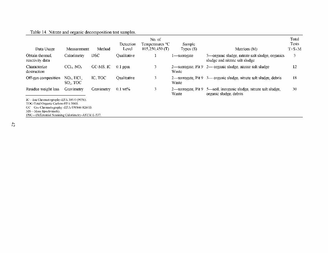
Table 14. Nitrate and organic decomposition test samples. No. of Total
Detection Temperatures "C Sample Tests Data Usage Measurement Method Level 105,250,450 (T) Types (9 Matrices (M) TxSxM
Obtain thermal, Calorimetry DSC Qualitative 1 1 -surrogate 3-organic sludge, nitrate salt sludge, organics 3 reactivity data
destruction Waste
SO2, TOC Waste
sludge and nitrate salt sludge Characterize CC14, NO3 GC-MS, IC 0.1 ppm 3 2-surrogate, Pit 9 2- organic sludge, nitrate salt sludge 12
Off-gas composition NO,, HC1, IC, TOC Qualitative 3 2-surrogate, Pit 9 3- organic sludge, nitrate salt sludge, debris 18
Residue weight loss Gravimetry Gravimetry 0.1 wt% 3 2-surrogate, Pit 9 5-soil, inorganic sludge, nitrate salt sludge, 30
IC-Ion Chromatography-EPA 300.0 (9056). TOC-Total Organic Carbon-EPA 9060. GC-Gas Chromatography -EPA-SW846 8260B. MS-Mass Spectrometry. DSC-Differential Scanning Calorimetry-ASTM E-537.
Waste organic sludge, debris
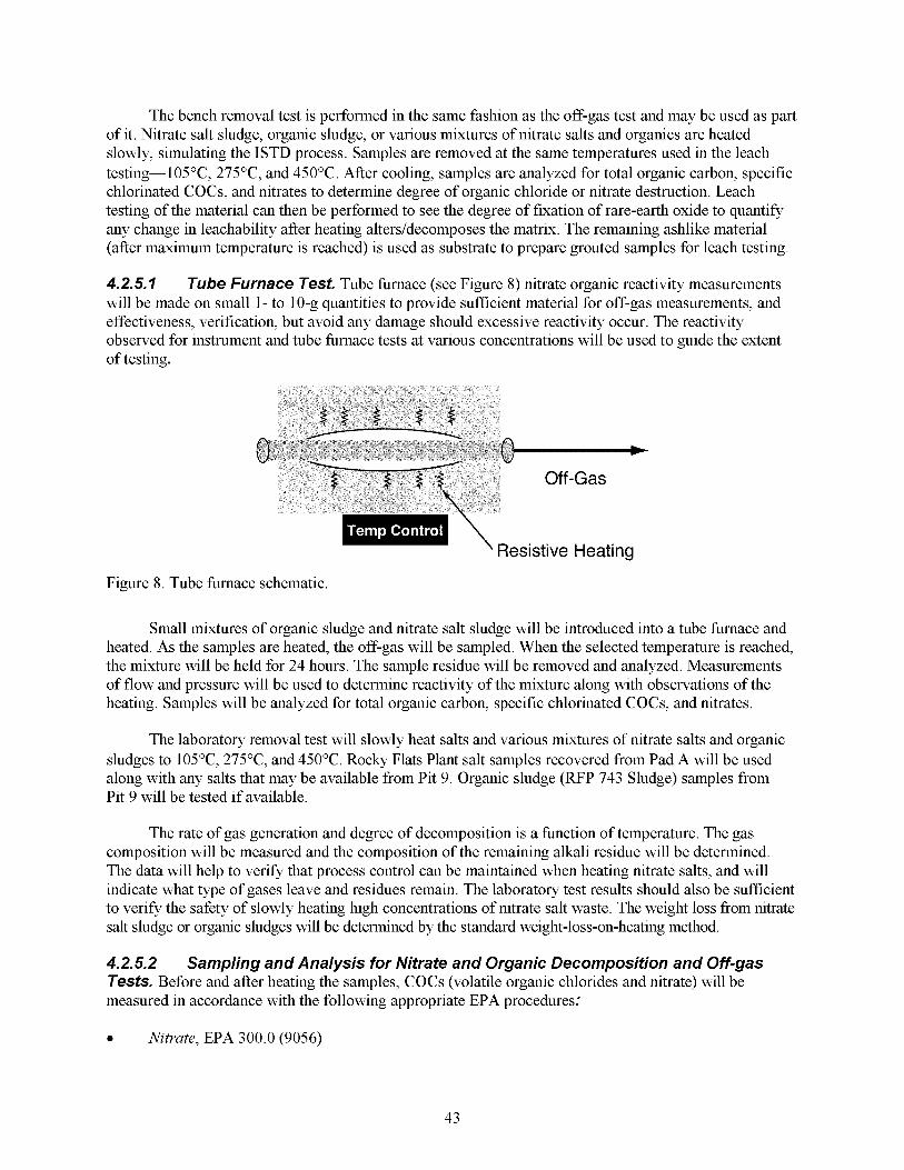
The bench removal test is performed in the same fashion as the off-gas test and may be used as part of it. Nitrate salt sludge, organic sludge, or various mixtures of nitrate salts and organics are heated slowly, simulating the ISTD process. Samples are removed at the same temperatures used in the leach testing-l05"C, 275"C, and 450°C. After cooling, samples are analyzed for total organic carbon, specific chlorinated COCs, and nitrates to determine degree of organic chloride or nitrate destruction. Leach testing of the material can then be performed to see the degree of fixation of rare-earth oxide to quantify any change in leachability after heating alters/decomposes the matrix. The remaining ashlike material (after maximum temperature is reached) is used as substrate to prepare grouted samples for leach testing.
4.2.5.7 Tube Furnace Test- Tube hrnace (see Figure 8) nitrate organic reactivity measurements will be made on small 1- to 10-g quantities to provide sufficient material for off-gas measurements, and effectiveness, verification, but avoid any damage should excessive reactivity occur. The reactivity observed for instrument and tube hrnace tests at various concentrations will be used to guide the extent of testing.
Resistive Heating
Figure 8 . Tube hrnace schematic.
Small mixtures of organic sludge and nitrate salt sludge will be introduced into a tube hrnace and heated. As the samples are heated, the off-gas will be sampled. When the selected temperature is reached, the mixture will be held for 24 hours. The sample residue will be removed and analyzed. Measurements of flow and pressure will be used to determine reactivity of the mixture along with observations of the heating. Samples will be analyzed for total organic carbon, specific chlorinated COCs, and nitrates.
The laboratory removal test will slowly heat salts and various mixtures of nitrate salts and organic sludges to 105"C, 275"C, and 450°C. Rocky Flats Plant salt samples recovered from Pad A will be used along with any salts that may be available from Pit 9. Organic sludge (RFP 743 Sludge) samples from Pit 9 will be tested if available.
The rate of gas generation and degree of decomposition is a hnction of temperature. The gas composition will be measured and the composition of the remaining alkali residue will be determined. The data will help to verify that process control can be maintained when heating nitrate salts, and will indicate what type of gases leave and residues remain. The laboratory test results should also be sufficient to verify the safety of slowly heating high concentrations of nitrate salt waste. The weight loss from nitrate salt sludge or organic sludges will be determined by the standard weight-loss-on-heating method.
4.2.5.2 Tests. Before and after heating the samples, COCs (volatile organic chlorides and nitrate) will be measured in accordance with the following appropriate EPA procedures:
Sampling and Analysis for Nitrate and Organic Decomposition and Off-gas
0 Nitrate, EPA 300.0 (9056)
43

0 Total Organic Carbon, EPA 9060
0 Volatile Organic Chlorides. EPA-SW846 8260B.
The degree of COC removal is a hnction of temperature. Samples of waste material at each temperature will be analyzed. The weight loss is determined by the standard weight-loss-on-heating method. At mid temperatures with incomplete removal, a mass balance with the off-gas content measured above will be attempted (see Table 14).
4.2.6 Required Test-Leachability
Though the primary purpose of ISTD is to destroy organic contaminants, any retardation of actinide leaching is desirable.
The purpose of the leach testing is to evaluate any changes in mobility of actinide contaminants upon heating soils and sludges to demonstrate the effectiveness of the ISTD process at immobilizing these inorganic COCs from aqueous transport. During the ISTD process, buried waste is heated such that chemical and physical changes occur both in the matrix and the contaminants. Nonvolatile metals and radionuclides may remain unchanged or partition into new or altered phases of soil and waste during treatment. The changes in soil and waste from heating may alter the mobility of some nonvolatile COCs.
Actinide fixation on the soil and waste is best studied at the laboratory scale because of the following:
Data are not scale-dependent, and thus can be obtained without field-scale testing
Data cannot be obtained from a nonradioactive simulated field-scale test
Data are needed to hlly understand the effects of treatment to support post-ROD design
Data are more easily quantifiable because the media can be better characterized before treatment.
The leach test will be performed on three types of material:
0
0
0
Rare-earth elements spiked surrogate matrices
Radiological actinide spiked surrogate matrices
Soil and waste samples from Glovebox Excavator Method Pit 9 retrieval.
Quantifying the change in actinide contaminant leachability from SDA waste media can benefit as input to the residual risk modeling for TRU COCs after the ISTD-process. Subsurface Disposal Area radiological Glovebox Excavator Method-produced waste samples will be used to determine the effect of heat on the leachability of actinides and other inorganic COCs remaining in the waste following ISTD. This testing will quantify physical and chemical changes that might change leaching properties and evaluate actinide contaminant fate and transport in SDA waste media, before and after heating.
In this phase of the bench testing, surrogate and SDA Glovebox Excavator Method-produced waste samples (matrices and contaminants) will be heated in a controlled bench setting. After cooling, samples are analyzed and leach tested to quantify any change in leachability after heating alters, or even decomposes, the matrix.
A substantial amount of information exists on the movement of TRU material from and through various soils. Many bench studies have been done on leaching of actinides and mixed fission products
44
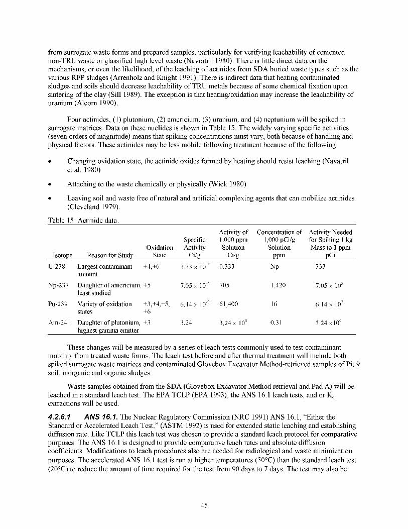
from surrogate waste forms and prepared samples, particularly for verifying leachability of cemented non-TRU waste or glassified high level waste (Navratril 1980). There is little direct data on the mechanisms, or even the likelihood, of the leaching of actinides from SDA buried waste types such as the various RFP sludges (Arrenholz and Knight 1991). There is indirect data that heating contaminated sludges and soils should decrease leachability of TRU metals because of some chemical fixation upon sintering of the clay (Sill 1989). The exception is that heating/oxidation may increase the leachability of uranium (Alcorn 1990).
Four actinides, (1) plutonium, (2) americium, (3) uranium, and (4) neptunium will be spiked in surrogate matrices. Data on these nuclides is shown in Table 15. The widely varying specific activities (seven orders of magnitude) means that spiking concentrations must vary, both because of handling and physical factors. These actinides may be less mobile following treatment because of the following:
Changing oxidation state, the actinide oxides formed by heating should resist leaching (Navatril et al. 1980)
Attaching to the waste chemically or physically (Wick 1980)
Leaving soil and waste free of natural and artificial complexing agents that can mobilize actinides (Cleveland 1979).
Table 15. Actinide data Activity of Concentration of
Specific 1,000 ppm 1,000 pCilg Oxidation Activity Solution Solution
Isotope Reason for Study State Cilg Cilg PPm U-238 Largest contaminant +4,+6 3.33 x 0.333 NP
amount
least studied Np-237 Daughter of americium, +5 7.05 x 705 1,420
Pu-239 Variety of oxidation +3,+4,+5, 6.14 x 61,400 16 states +6
Activity Needed for Spiking 1 kg Mass to 1 ppm
pCi 333
7.05 io5
6.14 io7
Am-24 1 Daughter of plutonium, +3 3.24 3.24 x lo6 0.3 1 3.24 x10⁹ highest gamma emitter
These changes will be measured by a series of leach tests commonly used to test contaminant mobility from treated waste forms. The leach test before and after thermal treatment will include both spiked surrogate waste matrices and contaminated Glovebox Excavator Method-retrieved samples of Pit 9 soil, inorganic and organic sludges.
leached in a standard leach test. The EPA TCLP (EPA 1993), the ANS 16.1 leach tests, and or Kd
extractions will be used.
4.2.6.7 ANS 76.7. The Nuclear Regulatory Commission (NRC 1991) ANS 16.1, “Either the Standard or Accelerated Leach Test,” (ASTM 1992) is used for extended static leaching and establishing diffusion rate. Like TCLP this leach test was chosen to provide a standard leach protocol for comparative purposes. The ANS 16.1 is designed to provide comparative leach rates and absolute diffusion coefficients. Modifications to leach procedures also are needed for radiological and waste minimization purposes. The accelerated ANS 16.1 test is run at higher temperatures (50°C) than the standard leach test (20°C) to reduce the amount of time required for the test from 90 days to 7 days. The test may also be
Waste samples obtained from the SDA (Glovebox Excavator Method retrieval and Pad A) will be
45
modified to use a groundwater simulant (as will be done in this test plan) in place of the standard deionized water (DI) water to more accurately reflect the conditions expected in the field. . The composition of recharge/infiltration water is variable, starting off as slightly acidic distilled water (rain) and quickly approaching the composition of ground water as it interacts with the soil. To minimize variation, ground water is generally used for leach testing, where distilled water is not used, for both comparability and standardization purposes. For testing of the solidification agents for nitrate salt sludge, the salts in addition to dissolved contaminants like chromium can be monitored.
4.2.6.2 for granular soils and wastes. Triplicate samples of solids (organic sludge, inorganic sludge, and soil) obtained from each of the temperature ranges will be leach tested. The samples are coarsely ground to small (<9 mm) particles for handling. The surface area is determined by calculation based on sieve size. Samples that are 1-5 g are weighed to the nearest mg in an acid-washed glass test tube.
The Kd test ratio of liquid to solid is maintained at 10: 1, but the required volume can be as low as 10 mL if using 1 g of sample. The analytes are actinides. The initial extractant is the same pH 8 ground-water simulant used in ANS 16.1. Agitation times are initially 24 hours. The supernatant is collected and its concentration is compared with the original concentration in the solid. The result can be verified by washing the solid once with methanol, then digesting it and confirm that the mass balances.
assigned per unit mass of soil in mg/Kg. [M]solutlon is the dissolved concentration of metal in equilibrium with the solid in mg/L. In dilute solutions, a plot of [MI in solution (abscissa) as a hnction of [MI assigned to solid (ordinate) should be linear. Treat with regression analysis and the slope = Kd.
4.2.6.3 (involving hot surrogates and real waste) are listed in Table 16. Sufficient surrogates will be prepared for the bench tests to allow triplicates of each type of leach test on material processed at each of the four ISTD process temperatures, including ambient. Solutions of Am, Pu, Np, and U nitrate will be added to INEEL soil, organic sludge surrogate, and inorganic sludge surrogate. Each waste matrix will be made up nominally to a concentration of 2 nCi/g. Terbium is one rare-earth element used in existing cold pits and will be used in bench tests along with cerium and dysprosium for nonradiological spiking on each matrix. Testing will also be done with Pit 9 sludges (organic, inorganic, and nitrate salt, as available) and INEEL
Kd. The Kd has been used in the past for radionuclide leaching and needs little modification
The measured Kd = [M]so~l~/[M]so~utlon; the units of measure are mL/g. [MIsolld is the amount of metal
Sampling and Analysis for Leaching. Sampling and analysis for ISTD leaching tests
soil.
0
0
0
0
0
The concentration of spiking depends on the following:
Results from characterization activities
Standardized solutions available
Leach amounts and potential retention expected
Radiological and rare-earth analysis detection limits
Radiological limits for this type of waste and test in INEEL laboratories.
46
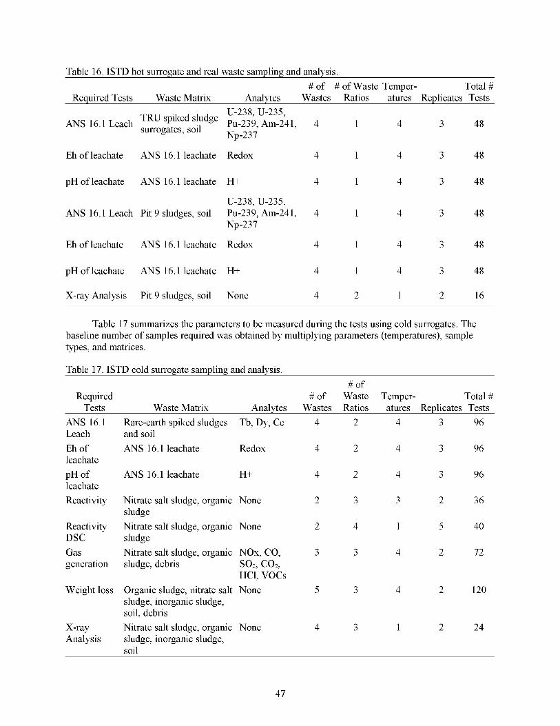
Table 16. ISTD hot surrogate and real waste sampling and analysis. # of # of Waste Temper- Total #
Required Tests Waste Matrix Analytes Wastes Ratios atures Replicates Tests
Eh of leachate ANS 16.1 leachate Redox
pH of leachate ANS 16.1 leachate H+
U-238, U-235, ANS 16.1 Leach Pit 9 sludges, soil Pu-239, Am-241,
Np-237
Eh of leachate ANS 16.1 leachate Redox
pH of leachate ANS 16.1 leachate H+
X-ray Analysis Pit 9 sludges, soil None
4 1 4 3 48
4 1 4 3 48
4 1 4 3 48
4 1 4 3 48
4 1 4 3 48
4 1 4 3 48
4 2 1 2 16
Required Tests
ANS 16.1 Leach Eh of leachate pH of leachate Reactivity
Reactivity DSC Gas generation
Weight loss
X-ray Analysis
-
Table 17 summarizes the parameters to be measured during the tests using cold surrogates. The baseline number of samples required was obtained by multiplying parameters (temperatures), sample types, and matrices.
Table 17. ISTD cold surrogate sampling and analysis.
-
# of # of Waste Temper- Total #
Waste Matrix Analytes Wastes Ratios atures Replicates Tests Rare-earth spiked sludges Tb, Dy, Ce 4 2 4 3 96 and soil ANS 16.1 leachate Redox 4 2 4 3 96
ANS 16.1 leachate H+ 4 2 4 3 96
Nitrate salt sludge, organic None 2 3 3 2 36 sludge Nitrate salt sludge, organic None 2 4 1 5 40 sludge Nitrate salt sludge, organic NOx, CO, 3 3 4 2 72 sludge, debris so2, co2,
Organic sludge, nitrate salt None 5 3 4 2 120 HC1, VOCs
sludge, inorganic sludge, soil, debris Nitrate salt sludge, organic None 4 3 1 2 24 sludge, inorganic sludge, soil
47
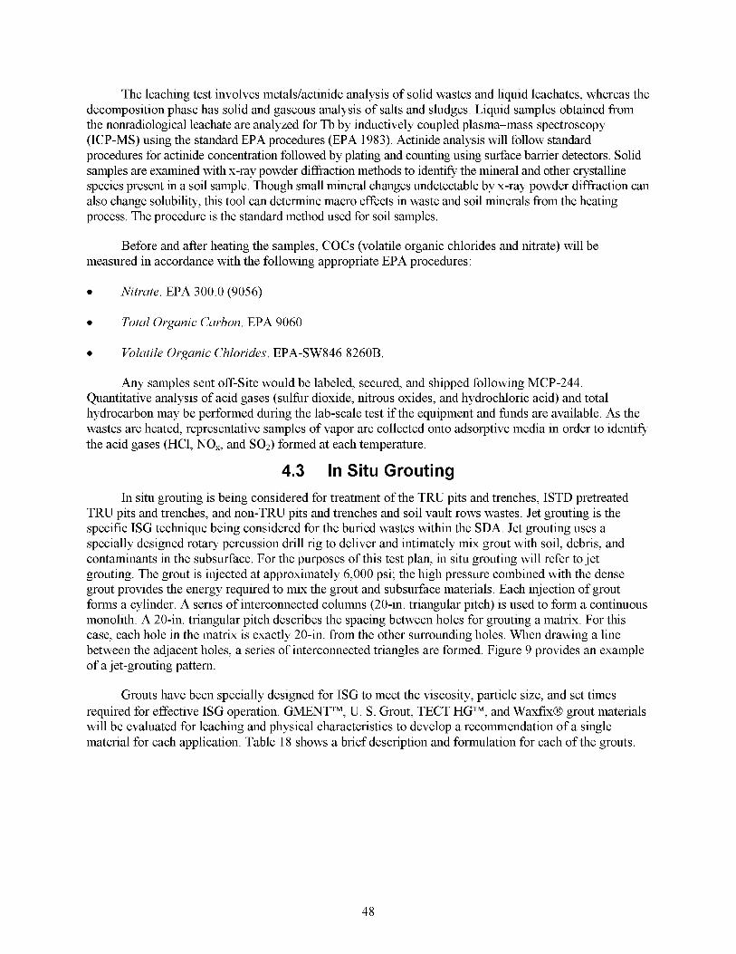
The leaching test involves metaldactinide analysis of solid wastes and liquid leachates, whereas the decomposition phase has solid and gaseous analysis of salts and sludges. Liquid samples obtained from the nonradiological leachate are analyzed for Tb by inductively coupled plasma-mass spectroscopy (ICP-MS) using the standard EPA procedures (EPA 1983). Actinide analysis will follow standard procedures for actinide concentration followed by plating and counting using surface barrier detectors. Solid samples are examined with x-ray powder difiaction methods to identify the mineral and other crystalline species present in a soil sample. Though small mineral changes undetectable by x-ray powder diffraction can also change solubility, this tool can determine macro effects in waste and soil minerals from the heating process. The procedure is the standard method used for soil samples.
Before and after heating the samples, COCs (volatile organic chlorides and nitrate) will be measured in accordance with the following appropriate EPA procedures :
Nitrate. EPA 300.0 (9056)
Total Organic Carbon. EPA 9060
Volatile Organic Chlorides. EPA-SW846 8260B.
Any samples sent off-Site would be labeled, secured, and shipped following MCP-244. Quantitative analysis of acid gases (sulhr dioxide, nitrous oxides, and hydrochloric acid) and total hydrocarbon may be performed during the lab-scale test if the equipment and hnds are available. As the wastes are heated, representative samples of vapor are collected onto adsorptive media in order to identify the acid gases (HC1, NO,, and SOz) formed at each temperature.
4.3 In Situ Grouting In situ grouting is being considered for treatment of the TRU pits and trenches, ISTD pretreated
TRU pits and trenches, and non-TRU pits and trenches and soil vault rows wastes. Jet grouting is the specific ISG technique being considered for the buried wastes within the SDA. Jet grouting uses a specially designed rotary percussion drill rig to deliver and intimately mix grout with soil, debris, and contaminants in the subsurface. For the purposes of this test plan, in situ grouting will refer to jet grouting. The grout is injected at approximately 6,000 psi; the high pressure combined with the dense grout provides the energy required to mix the grout and subsurface materials. Each injection of grout forms a cylinder. A series of interconnected columns (20-in. triangular pitch) is used to form a continuous monolith. A 20411. triangular pitch describes the spacing between holes for grouting a matrix. For this case, each hole in the matrix is exactly 20-in. from the other surrounding holes. When drawing a line between the adjacent holes, a series of interconnected triangles are formed. Figure 9 provides an example of a jet-grouting pattern.
Grouts have been specially designed for ISG to meet the viscosity, particle size, and set times required for effective ISG operation. GMENTTM, U. S. Grout, TECT HGTM, and WaxfixB grout materials will be evaluated for leaching and physical characteristics to develop a recommendation of a single material for each application. Table 18 shows a brief description and formulation for each of the grouts.
48
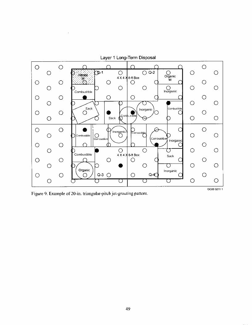
Layer 1 Long-Term Disposal I
0 0 0
0 0 0
0 0 0
0 0 0
0 0 0
0 0 0
0 0 0
0 0 0
0 4 x 4
1 Combustible +%-Lo 8
0 0
0 C, C 0 0
0 Q-K) C 0 0
8-fl BOX Sack
Inorganic
0
0
0
0 -
0
0
0
0
0
0
0
0
0
0
0
0
0
0
0
0
0
0
0
0 GCOO 0211 1
Figure 9. Example of 20-in. triangular-pitch jet-grouting pattern.
49
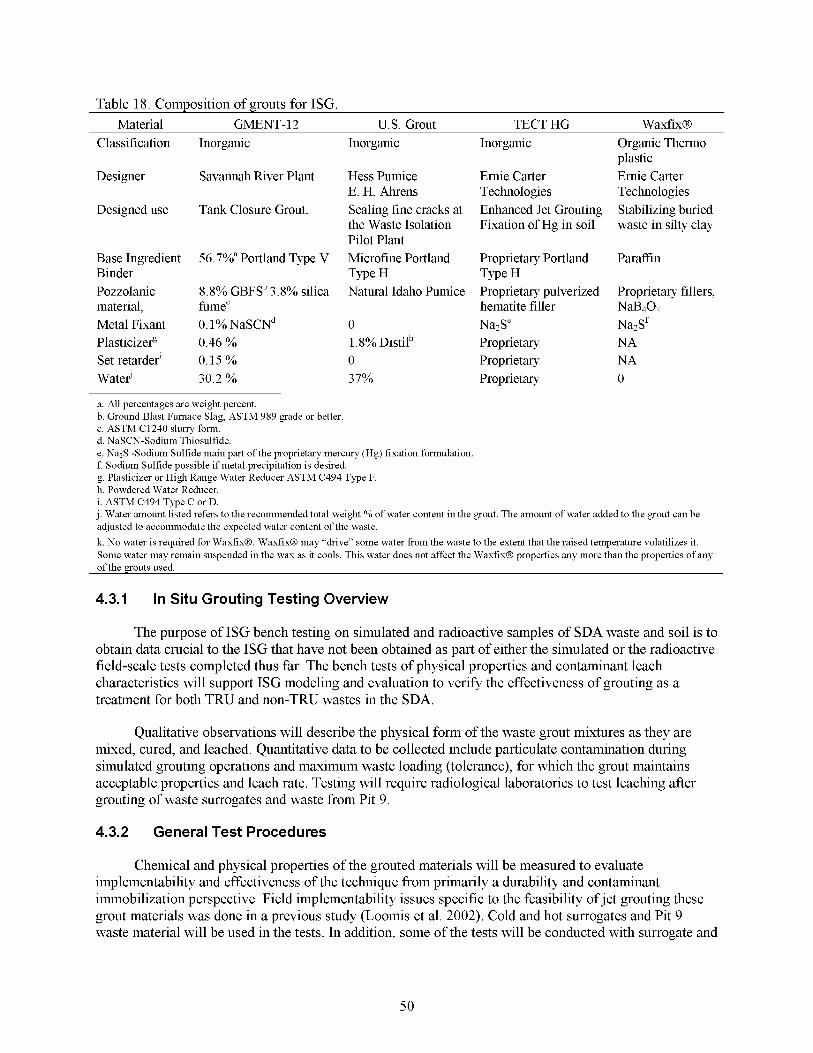
Table 18. Composition of grouts for ISG. Material GMENT- 12 U.S. Grout TECT HG Waxfix@
Classification Inorganic
Designer Savannah River Plant
Designed use Tank Closure Grout.
Base Ingredient 56.7%" Portland Type V Binder Pozzolanic 8.8% GBFSb 3.8% silica material, hmec Metal Fixant 0.1% NaSCNd Plasticizefl 0.46 % Set retarder' 0.15 % Water' 30.2 %
a. All percentages are weight percent. b. Ground Blast Furnace Slag, ASTM 989 grade or better c. ASTM C1240 slurry form. d. NaSCN-Sodium Thiosulfide.
Inorganic
Hess Pumice E. H. Ahrens Sealing fine cracks at the Waste Isolation Pilot Plant Microfine Portland Type H Natural Idaho Pumice
0 1.8% Distilh 0 37%
Inorganic
Ernie Carter Technologies Enhanced Jet Grouting Fixation of Hg in soil
Proprietary Portland Type H Proprietary pulverized hematite filler Na2Se Proprietary Proprietary Proprietary
Organic Thermo plastic Ernie Carter Technologies Stabilizing buried waste in silty clay
Paraffin
Proprietary fillers, Na407 Na2Sf NA NA 0
e. NazS -Sodium Sulfide main part of the proprietary mercury (Hg) fixation formulation. f Sodium Sulfide possible if metal precipitation is desired. g. Plasticizer or High Range Water Reducer ASTM C494 Type F. h. Powdered Water Reducer. i. ASTM C494 Type C or D. j . Water amount listed refers to the recommended total weight YO of water content in the grout. The amount of water added to the grout can be adjusted to accommodate the expected water content of the waste. k. No water is required for WaxfixB. WaxfixB may "drive" some water from the waste to the extent that the raised temperature volatilizes it. Some water may remain suspended in the wax as it cools. This water does not affect the WaxfixB properties any more than the properties of any of the grouts used.
4.3.1 In Situ Grouting Testing Overview
The purpose of ISG bench testing on simulated and radioactive samples of SDA waste and soil is to obtain data crucial to the ISG that have not been obtained as part of either the simulated or the radioactive field-scale tests completed thus far. The bench tests of physical properties and contaminant leach characteristics will support ISG modeling and evaluation to verify the effectiveness of grouting as a treatment for both TRU and non-TRU wastes in the SDA.
Qualitative observations will describe the physical form of the waste grout mixtures as they are mixed, cured, and leached. Quantitative data to be collected include particulate contamination during simulated grouting operations and maximum waste loading (tolerance), for which the grout maintains acceptable properties and leach rate. Testing will require radiological laboratories to test leaching after grouting of waste surrogates and waste from Pit 9.
4.3.2 General Test Procedures
Chemical and physical properties of the grouted materials will be measured to evaluate implementability and effectiveness of the technique from primarily a durability and contaminant immobilization perspective. Field implementability issues specific to the feasibility of jet grouting these grout materials was done in a previous study (Loomis et al. 2002). Cold and hot surrogates and Pit 9 waste material will be used in the tests. In addition, some of the tests will be conducted with surrogate and
50

waste material previously treated via ISTD. Four grouts will be used in testing (Table 18). The test grouts were chosen from previous field testing for their jet “groutability” and bench testing of compatibility with waste matrices present at SDA.
Each waste matrix is mixed with a candidate grout, poured into mold and cured at 100% humidity for 14 days. Physical properties and leachability of the resulting monoliths will be determined. Particulates resulting during grouting will be measured and hydrogen generation from actual wastes in a grouted matrix will be examined. The physical strength of a particular waste matrix or INEEL soil and grout mix will be determined by mixing progressively higher amounts of waste with grout and measuring compressive strength.
4.3.3 ISG of TRU Pits and Trenches Waste
Four objectives of the test plan are addressed by the bench testing relating to the TRU pits and trenches.
Objective 1. Develop Data to Support Contaminant Transport Modeling for Treated Waste Forms.
0 Objective 2. Evaluate Durability of Grouted Waste.
0 Objective 3. Evaluate release of radionuclide particulate during grouting.
0 Objective 4. Evaluate WaxfixB for use as a grout.
Table 19 provides a summary of the testing for ISG of TRU pits and trenches wastes
Table 19. Summary of testing for ISG of TRU pits and trenches wastes.
Test Matrix
Required Test Cold Surrogate Hot Surrogate Waste - Compositional Analysis X
Compressive Strength X - -
Boron Retention and Distribution X - -
Hydraulic Conductivity X - -
Fracture Propagation
DOT Oxidizer
X
X
Macroencapsulation X - -
Microencapsulation X - -
Leachability X X
PH X X
- Plutonium Aerosolization X -
-
-
- Eh X X
51
4.3.3.7 composited samples of each waste type obtained from Pit 9 before using the waste in other tests. It is expected that three types of waste will be obtained: organic sludge, inorganic sludge, and nitrate salt sludge. Each waste type will be received in several jars. The jars will be combined before analysis to simplify the subsequent tests.
Required Test-Compositional Analysis. Compositional analysis will be performed on
Sampling and Analysis for Compositional Analysis. For a summary of sampling and analysis data for compositional analysis for ISG of TRU pits and trenches wastes, see Table 20.
Table 20. Compositional analysis of material obtained from Pit-9 material.
Total Test Method Analytes Replicates Samples
Mixed Fission Products
Mixed Fission Products
Minor and Trace Metals
SVOA, Polychlorinated Biphenyls (PCBs)
Nonmetals
Eh of wash
TRU Content
Total Organic Carbon
TOX
VOA
Anions of wash
pH of wash
Major Metals
Ash
Beta Spec
Gamma Spec
ICP-MS
Gas Chromatography- Mass Spectrometry
Leico@ Analyzer
ASTM D 1498-76
Alpha Spec
Dohrman@ Analyzer
Dohrman@ Analyzer
Gas Chromatography- Mass Spectrometry
Ion Chromatography
X-ray Fluorescence
Muffle Furnace
Tc-99, C-14, H-3, Sr-90, 1-129
CS-137, CO-60, Nb-94
Ca, Fe, B, Be, Zn, Cu, B, Al, S, Ti, Cr
Polychlorinated Biphenyls (PCBs), Semi Volatile Organics
s, N, c Redox
U-238, U-235, U-234, PU-239, Pu-238, Am-241, Np-237
Organic Carbon
Chlorinated Organic Carbon
Volatile Organics, CC4, TCA etc
Cl-, Fl-, Br-, NO;, NOs-, SOi2
H+
Si, Ca, Fe, Na, Mg, K, S, A1
Si, Ca, Fe, Mg, Na, K, S, 0, A1
3 3
3 3
3 3
3 3
3 3
3 3
3 3
3 3
3 3
3 3
3 3
3 3
3 3
3 3
4.3.3.2 with a past ISG treatability study, it was determined that WaxfixB grout material could not keep the particulate Boron- 10 (B- 10 contained in NaB407 dissolved in glycerin) additive suspended in the wax during the 5-day controlled cooling process. New information has indicated that the reformulated
Required Test-Boron Retention and Distribution. During bench testing associated
52
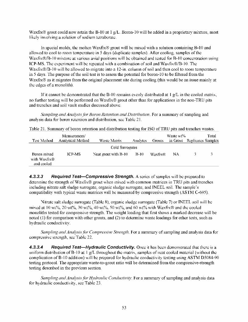
WaxfixB grout could now retain the B-10 at 1 g/L. Boron-10 will be added in a proprietary mixture, most likely involving a solution of sodium tetraborate.
In special molds, the molten WaxfixB grout will be mixed with a solution containing B-10 and allowed to cool to room temperature in 5 days (duplicate samples). After cooling, samples of the WaxfixB/B- 10 mixture at various axial positions will be obtained and tested for B- 10 concentration using ICP-MS. The experiment will be repeated with a combination of soil and WaxfixB/B-10. The WaxfixB/B-10 will be allowed to migrate into a 12411. column of soil and then cool to room temperature in 5 days. The purpose of the soil test is to assess the potential for boron-10 to be filtered from the WaxfixB as it migrates from the original placement site during cooling (this would be an issue mainly at the edges of a monolith).
If it cannot be demonstrated that the B-10 remains evenly distributed at 1 g/L in the cooled matrix, no hrther testing will be performed on WaxfixB grout other than for applications in the non-TRU pits and trenches and soil vault studies discussed above.
Sampling and Analysis for Boron Retention and Distribution. For a summary of sampling and analysis data for boron retention and distribution, see Table 2 1.
Table 2 1. Summarv of boron retention and distribution testing for ISG of TRU Dits and trenches wastes
Measurement/ Waste wt% Total Test Method Analytical Method Waste Matrix Analytes Grouts in Grout Replicates Samples
Cold Surrogates Boron mixed ICP-MS Neat grout with B-10 B-10 Waxfix@ NA 3 3
with Waxfix@ and cooled
4.3.3.3 determine the strength of WaxfixB grout when mixed with common matrices in TRU pits and trenches including nitrate salt sludge surrogate, organic sludge surrogate, and INEEL soil. The sample’s compatibility with typical waste matrices will be measured by compressive strength (ASTM C-695).
Required Test-Compressive Strength. A series of samples will be prepared to
Nitrate salt sludge surrogate (Table 8), organic sludge surrogate (Table 7) or INEEL soil will be mixed at 10 wt%, 20 wt%, 30 wt%, 40 wt%, 50 wt%, and 60 wt% with WaxfixB and the cooled monoliths tested for compressive strength. The weight loading that first shows a marked decrease will be noted (1) for comparison with other grouts, and (2) to determine waste loadings for other tests, such as hydraulic conductivity.
Sampling and Analysis for Compressive Strength. For a summary of sampling and analysis data for compressive strength, see Table 22.
4.3.3.4 Required Test-Hydraulic Conductivity. Once it has been demonstrated that there is a uniform distribution of B-10 at 1 g/L throughout the matrix, samples of neat cooled material (without the complication of B- 10 addition) will be prepared for hydraulic conductivity testing using ASTM D5084-90 testing protocol. The appropriate waste-to-grout ratio will be determined from the compressive-strength testing described in the previous section.
Sampling and Analysis for Hydraulic Conductivity, For a summary of sampling and analysis data for hydraulic conductivity, see Table 23.
53
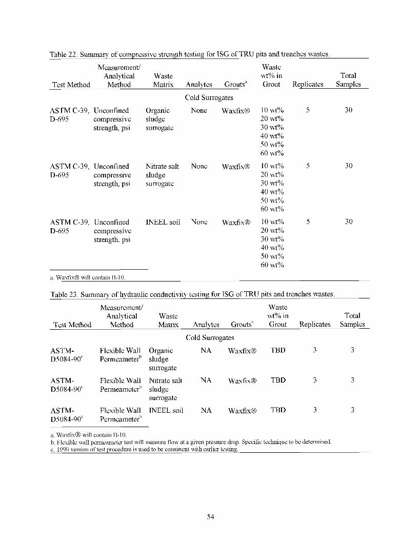
Table 22. Summary of compressive strength testing for ISG of TRU pits and trenches wastes.
Measurement/ Waste Analytical Waste wt% in Total
Test Method Method Matrix Analytes Grouts” Grout Replicates Samples
Cold Surrogates
ASTM C-39, Unconfined D-695 compressive
strength, psi
ASTM C-39, Unconfined D-695 compressive
strength, psi
ASTM C-39, Unconfined D-695 compressive
strength, psi
Organic None WaxfixB sludge surrogate
Nitrate salt None WaxfixB sludge surrogate
INEEL soil None WaxfixB
30
10 wt% 5 30 20 wt% 30 wt% 40 wt% 50 wt% 60 wt%
10 wt% 5 20 wt% 30 wt% 40 wt% 50 wt% 60 wt%
10 wt% 5 20 wt% 30 wt% 40 wt% 50 wt%
30
60 wt%
a. WaxfixB Will contain B-10.
Table 23. Summary of hydraulic conductivity testing for ISG of TRU pits and trenches wastes.
Measurement/ Waste Analytical Waste wt% in Total
Test Method Method Matrix Analytes Grouts” Grout Replicates Samples
Cold Surrogates
ASTM- Flexible Wall Organic NA WaxfixB TBD 3 3 D5084-90‘ Permeameterb sludge
ASTM- Flexible Wall Nitrate salt NA WaxfixB TBD 3 3 D5084-90‘ Permeameterb sludge
ASTM- Flexible Wall INEEL soil NA WaxfixB TBD 3 3 D5084-90‘ Permeameterb
a. Waxfix@ will contain B-IO. b. Flexible wall permeameter test will measure flow at a given pressure drop. Specific technique to be determined. c. 1990 version of test procedure is used to be consistent With earlier testing.
surrogate
surrogate
54
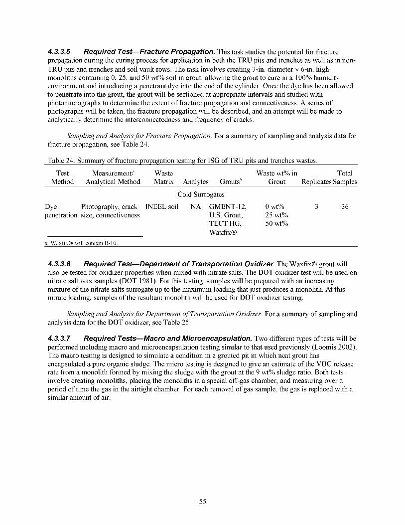
4.3.3.5 propagation during the curing process for application in both the TRU pits and trenches as well as in non- TRU pits and trenches and soil vault rows. The task involves creating 3-in. diameter x 6-in. high monoliths containing 0, 25, and 50 wt% soil in grout, allowing the grout to cure in a 100% humidity environment and introducing a penetrant dye into the end of the cylinder. Once the dye has been allowed to penetrate into the grout, the grout will be sectioned at appropriate intervals and studied with photomicrographs to determine the extent of fracture propagation and connectiveness. A series of photographs will be taken, the fracture propagation will be described, and an attempt will be made to analytically determine the interconnectedness and frequency of cracks.
Required Test-Fracture Propagation. This task studies the potential for fracture
Sampling and Analysis for Fracture Propagation. For a summary of sampling and analysis data for fracture propagation, see Table 24.
Table 24. Summary of fracture propagation testing for ISG of TRU pits and trenches wastes.
Test Measurement/ Waste Waste wt% in Total Method Analytical Method Matrix Analytes Grouts” Grout Replicates Samples
Cold Surrogates
Dye Photography, crack INEEL soil NA GMENT-12, 0 wt% 3 36 penetration size, connectiveness U.S. Grout, 25 wt%
TECT HG, 50 wt% WaxfixB
a. WaxfixB Will contain B-10.
4.3.3.6 also be tested for oxidizer properties when mixed with nitrate salts. The DOT oxidizer test will be used on nitrate salt wax samples (DOT 1981). For this testing, samples will be prepared with an increasing mixture of the nitrate salts surrogate up to the maximum loading that just produces a monolith. At this nitrate loading, samples of the resultant monolith will be used for DOT oxidizer testing.
Required Test-Department of Transportation Oxidizer. The WaxfixB grout will
Sampling and Analysis for Department of Transportation Oxidizer. For a summary of sampling and analysis data for the DOT oxidizer, see Table 25.
4.3.3.7 Required Tests-Macro and Microencapsulation. Two different types of tests will be performed including macro and microencapsulation testing similar to that used previously (Loomis 2002). The macro testing is designed to simulate a condition in a grouted pit in which neat grout has encapsulated a pure organic sludge. The micro testing is designed to give an estimate of the VOC release rate from a monolith formed by mixing the sludge with the grout at the 9 wt% sludge ratio. Both tests involve creating monoliths, placing the monoliths in a special off-gas chamber, and measuring over a period of time the gas in the airtight chamber. For each removal of gas sample, the gas is replaced with a similar amount of air.
55
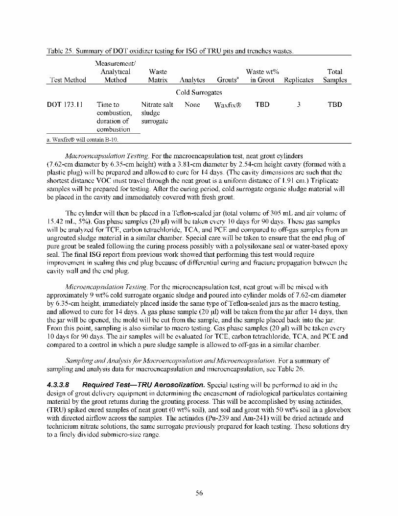
Table 25. Summarv of DOT oxidizer testing for ISG of TRU Dits and trenches wastes.
Measurement/ Analytical Waste Waste wt% Total
Test Method Method Matrix Analvtes Grouts” in Grout Replicates Samples
Cold Surrogates
DOT 173.11 Time to Nitrate salt None WaxfixB TBD 3 TBD combustion, sludge duration of surrogate combustion
a. WaxfixB Will contain B-10.
Microencapsulation Testing. For the macroencapsulation test, neat grout cylinders (7.62-cm diameter by 6.35-cm height) with a 3.81-cm diameter by 2.54-cm height cavity (formed with a plastic plug) will be prepared and allowed to cure for 14 days. (The cavity dimensions are such that the shortest distance VOC must travel through the neat grout is a uniform distance of 1.9 1 cm.) Triplicate samples will be prepared for testing. After the curing period, cold surrogate organic sludge material will be placed in the cavity and immediately covered with fresh grout.
The cylinder will then be placed in a Teflon-sealed jar (total volume of 305 mL and air volume of 15.42 mL, 5%). Gas phase samples (20 pl) will be taken every 10 days for 90 days. These gas samples will be analyzed for TCE, carbon tetrachloride, TCA, and PCE and compared to off-gas samples from an ungrouted sludge material in a similar chamber. Special care will be taken to ensure that the end plug of pure grout be sealed following the curing process possibly with a polysiloxane seal or water-based epoxy seal. The final ISG report from previous work showed that performing this test would require improvement in sealing this end plug because of differential curing and fracture propagation between the cavity wall and the end plug.
Microencapsulation Testing. For the microencapsulation test, neat grout will be mixed with approximately 9 wt% cold surrogate organic sludge and poured into cylinder molds of 7.62-cm diameter by 6.35-cm height, immediately placed inside the same type of Teflon-sealed jars as the macro testing, and allowed to cure for 14 days. A gas phase sample (20 pl) will be taken from the jar after 14 days, then the jar will be opened, the mold will be cut from the sample, and the sample placed back into the jar. From this point, sampling is also similar to macro testing. Gas phase samples (20 pl) will be taken every 10 days for 90 days. The air samples will be evaluated for TCE, carbon tetrachloride, TCA, and PCE and compared to a control in which a pure sludge sample is allowed to off-gas in a similar chamber.
Sampling and Analysis for Microencapsulation and Microencapsulation. For a summary of sampling and analysis data for macroencapsulation and microencapsulation, see Table 26.
4.3.3.8 design of grout delivery equipment in determining the encasement of radiological particulates containing material by the grout returns during the grouting process. This will be accomplished by using actinides, (TRU) spiked cured samples of neat grout (0 wt% soil), and soil and grout with 50 wt% soil in a glovebox with directed airflow across the samples. The actinides (Pu-239 and Am-241) will be dried actinide and technicium nitrate solutions, the same surrogate previously prepared for leach testing. These solutions dry to a finely divided submicro-size range.
Required Test-TRU Aerosolization. Special testing will be performed to aid in the
56
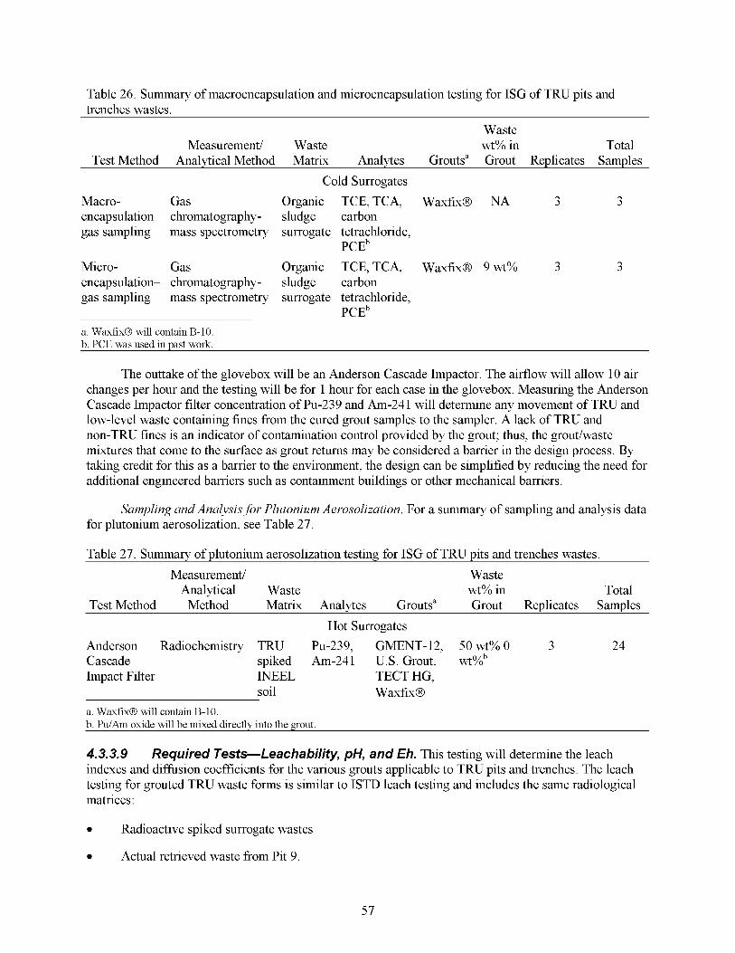
Table 26. Summary of macroencapsulation and microencapsulation testing for ISG of TRU pits and trenches wastes.
Waste Measurement/ Waste wt% in Total
Test Method Analytical Method Matrix Analytes Grouts” Grout Replicates Samples
Cold Surrogates Macro- Gas Organic TCE,TCA, WaxfixB NA 3 3 encapsulation- chromatography- sludge carbon gas sampling mass spectrometry surrogate tetrachloride,
PCEb Micro- Gas Organic TCE, TCA, WaxfixB 9 wt% 3 3 encapsulation- chromatography- sludge carbon gas sampling mass spectrometry surrogate tetrachloride,
a. WaxfixB Will contain B-10. b. PCE was used in past work.
PCEb
The outtake of the glovebox will be an Anderson Cascade Impactor. The airflow will allow 10 air changes per hour and the testing will be for 1 hour for each case in the glovebox. Measuring the Anderson Cascade Impactor filter concentration of Pu-239 and Am-24 1 will determine any movement of TRU and low-level waste containing fines from the cured grout samples to the sampler. A lack of TRU and non-TRU fines is an indicator of contamination control provided by the grout; thus, the grout/waste mixtures that come to the surface as grout returns may be considered a barrier in the design process. By taking credit for this as a barrier to the environment, the design can be simplified by reducing the need for additional engineered barriers such as containment buildings or other mechanical barriers.
Sampling and Analysis for Plutonium Aerosolization. For a summary of sampling and analysis data for plutonium aerosolization, see Table 27.
Table 27. Summary of plutonium aerosolization testing for ISG of TRU pits and trenches wastes.
Measurement/ Waste Analytical Waste wt% in Total
Test Method Method Matrix Analytes Grouts” Grout Replicates Samples
Hot Surrogates Anderson Radiochemistry TRU Pu-239, GMENT-12, 50 wt% 0 3 24 Cascade spiked Am-241 U.S. Grout, wt%b Impact Filter INEEL TECT HG,
a. WaxfixB Will contain B-10. b. PdAm oxide Will be mixed directly into the grout.
soil WaxfixB
4.3.3.9 indexes and diffusion coefficients for the various grouts applicable to TRU pits and trenches. The leach testing for grouted TRU waste forms is similar to ISTD leach testing and includes the same radiological matrices:
Required Tests-Leachability, pH, and Eh. This testing will determine the leach
Radioactive spiked surrogate wastes
Actual retrieved waste from Pit 9.
57
Soil, grout, and surrogate sludges will be prepared and spiked with nitrate solutions or metal oxides of Pu/Am/Np/U as described in Section 4.1. The spike amounts are expected to allow detection in the leachate assuming leach indexes of between 8 and 12 for the ANS 16.1 procedure or Kds in the thousands for the extractions.
The Glovebox Excavator Method project is expected to provide samples of organic sludge from Pit 9. Compositional analysis (see details in require test - compositional analysis) of this material will be performed before leach testing is done. The leach testing will use the retrieved Pit 9 sludge material in the purest form (not mixed with surrounding soil) possible. Assuming that organic sludge of similar consistency as the surrogate sludge samples used in previous studies (Loomis 2002), weight loadings of 5, 9, and 15 wt% Glovebox Excavator Method sludge will be mixed with each of the four neat grouts. A compositional analysis will be performed on the samples from Pit 9 before performing the leachability tests (see required tests-compositional analysis for details).
ANS 16.1 leach testing is performed on 2 x 4-in. right cylindrical monoliths. The resultant grout/contaminant or grout/waste mixtures are poured into 2-in. diameter x 4-in. high molds and are cured for 14 days in 100% relative humidity before leach testing. Using triplicate samples, the ANS 16.1 leaching protocol will be performed using a synthetic ground water with ph = 8 and the samples will kept in an inert atmosphere. Eh and pH of the leachate will be measured during the ANS 16.1 procedure.
While ANS 16.1 testing is designed for solid monoliths, Kd testing is designed to handle granular or particulate material. Higher loadings of organic sludge in the grouts will prevent the formation of a monolith. It is expected that in the field, there will be small regions of high organic sludge in grout (these will be surrounded by well set monolith), so some understanding of the leachability of these grouted regions is desired for modeling the overall leachability of the treated source term.
Kd leach testing will be performed on coarsely ground samples of grouted waste. A known amount (1-5 g for these tests) of ground sample is weighed into an acid-washed glass container. Extractant is added to result in a 10: 1 extractant to solid mass ratio. The initial extractant is the same pH 8 groundwater simulant used in ANS 16.1. Agitation times are initially 24 hours. The supernatant is collected and its concentration is compared with the original concentration in the solid.
The result can be verified by washing the solid once with methanol, then digesting it and confirming that the mass balances. The measured Kd = [M]solld/[M]solutlon; the units of measure are mL/g. [MIsolld is the amount of metal assigned per unit mass of soil in mg/Kg. [M]solutlon is the dissolved concentration of metal in equilibrium with the solid in mg/Liter. In dilute solutions, a plot of [MI in solution (abscissa) as a function of [MI assigned to solid (ordinate) should be linear, and the slope of the line is the value of Kd. Kds of 1,000 or greater are expected.
ANS 16.1 leach tests will be completed in triplicate using the four grouts (WaxfixB, GMENT-12, U.S. Grout, and TECT HG) neat-spiked (no soil or waste) with actinide oxides of Pu-239/Am-241/ Np-237/U-238 at a weight percent that allows detection assuming leach indexes of between 8-12 for the ANS 16.1 procedure. Leach indexes and diffusion coefficients will be determined from the procedure for Pu/Am/Np/U leaching from the matrix. Eh and pH of the leachate will be measured during this procedure.
ANS 16.1 leach tests will be completed in triplicate using 5 and 9 wt% organic sludge samples from Pit 9 and the four grouts (WaxfixB, GMENT-12, U.S. Grout, and TECT HG). Leach indexes and diffusion coefficients will be determined from the procedure for U-238, U-235, Pu-239, Am-241, and Np-237. Leach indexes and diffusion coefficient will be determined, as appropriate, based on the results of the compositional analysis of the Pit 9 material.
58
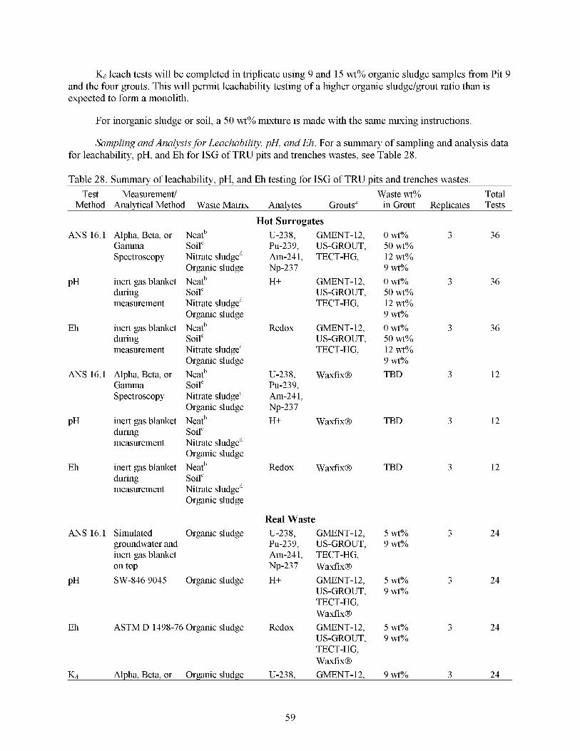
Kd leach tests will be completed in triplicate using 9 and 15 wt% organic sludge samples from Pit 9 and the four grouts. This will permit leachability testing of a higher organic sludge/grout ratio than is expected to form a monolith.
For inorganic sludge or soil, a 50 wt% mixture is made with the same mixing instructions.
Sampling and Analysis for Leachability, pH, and Eh. For a summary of sampling and analysis data for leachability, pH, and Eh for ISG of TRU pits and trenches wastes, see Table 28.
Table 28. Summary of leachability, pH, and Eh testing for ISG of TRU pits and trenches wastes. Test Measurement/ Waste wt% Total
Method Analytical Method Waste Matrix Analytes Grouts" in Grout Replicates Tests
ANS 16.1 Alpha, Beta, or Gamma Spectroscopy
PH inert gas blanket during measurement
Eh inert gas blanket during measurement
ANS 16.1 Alpha, Beta, or Gamma Spectroscopy
PH inert gas blanket during measurement
Eh inert gas blanket during measurement
Neatb Soil" Nitrate sludged Organic sludge Neatb Soil" Nitrate sludged Organic sludge Neatb Soil" Nitrate sludged Organic sludge Neatb Soil" Nitrate sludged Organic sludge Neatb Soil" Nitrate sludged Organic sludge Neatb Soil" Nitrate sludged Organic sludge
ANS 16.1 Simulated Organic sludge groundwater and inert gas blanket on top
PH SW-846 9045 Organic sludge
Eh ASTM D 1498-76 Organic sludge
Hot Surrogates U-238, GMENT-12, Pu-239, US-GROUT, Am-24 1, TECT-HG, Np-237 H+ GMENT- 12,
US-GROUT, TECT-HG,
Redox GMENT-12, US-GROUT, TECT-HG.
U-238, Waxfix@
Am-24 1,
H+ Waxfix@
Pu-239,
Np-237
Redox Waxfix@
Real Waste U-238, GMENT-12, Pu-239, US-GROUT, Am-24 1, TECT-HG, Np-237 Waxfix@ H+ GMENT- 12,
US-GROUT, TECT-HG, Waxfix@
Redox GMENT-12, US-GROUT, TECT-HG, Waxfix@
0 wt% 3 36 50 wt% 12 wt% 9 wt%
0 wt% 3 36 50 wt% 12 wt% 9 wt%
0 wt% 3 36 50 wt% 12 wt% 9 wt%
TBD 3 12
TBD
TBD
3 12
3 12
5 wt% 3 24 9 wt%
5 wt% 3 24 9 wt%
5 wt% 3 24 9 wt%
Kd Alpha, Beta, or Organic sludge U-238, GMENT-12, 9 wt% 3 24
59
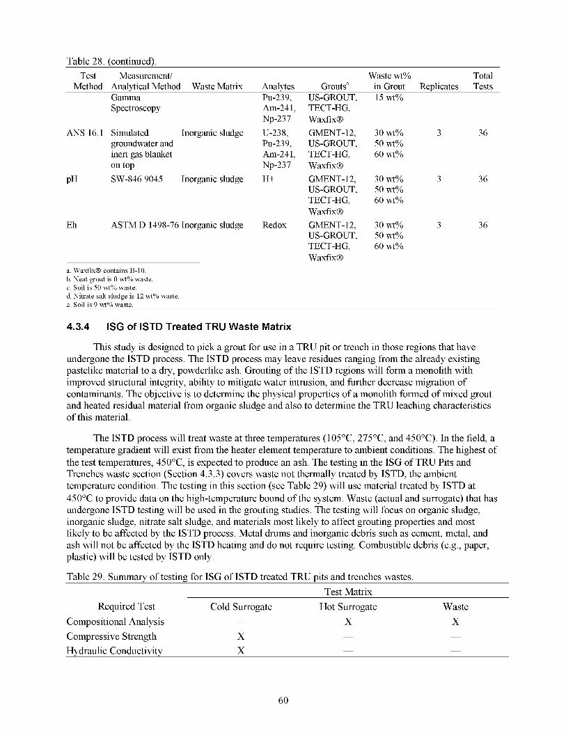
Table 28. (continued). Test Measurement/ Waste wt% Total
Method Analytical Method Waste Matrix Analytes Grouts" in Grout Replicates Tests Gamma Spectroscopy
ANS 16.1 Simulated Inorganic sludge groundwater and inert gas blanket on top
PH SW-846 9045 Inorganic sludge
Eh ASTM D 1498-76 Inorganic sludge
a. WaxfixB contains B-10. b. Neat grout is 0 wt% waste. c. Soil is 50 wt% waste. d. Nitrate salt sludge is 12 wt% waste. e. Soil is 9 wt% waste.
~
4.3.4 ISG of ISTD Treated TRU Waste Matrix
PU-239, Am-24 1, Np-237 U-238, PU-239, Am-24 1, Np-237 H+
Redox
US-GROUT, TECT-HG, Waxfix@ GMENT- 12, US-GROUT, TECT-HG, Waxfix@ GMENT- 12, US-GROUT, TECT-HG, Waxfix@ GMENT- 12, US-GROUT, TECT-HG, Waxfix@
15 wt%
30 wt% 3 36 50 wt% 60 wt%
30 wt% 3 36 50 wt% 60 wt%
30 wt% 3 36 50 wt% 60 wt%
This study is designed to pick a grout for use in a TRU pit or trench in those regions that have undergone the ISTD process. The ISTD process may leave residues ranging from the already existing pastelike material to a dry, powderlike ash. Grouting of the ISTD regions will form a monolith with improved structural integrity, ability to mitigate water intrusion, and hrther decrease migration of contaminants. The objective is to determine the physical properties of a monolith formed of mixed grout and heated residual material from organic sludge and also to determine the TRU leaching characteristics of this material.
The ISTD process will treat waste at three temperatures (105"C, 275"C, and 450°C). In the field, a temperature gradient will exist from the heater element temperature to ambient conditions. The highest of the test temperatures, 450"C, is expected to produce an ash. The testing in the ISG of TRU Pits and Trenches waste section (Section 4.3.3) covers waste not thermally treated by ISTD, the ambient temperature condition. The testing in this section (see Table 29) will use material treated by ISTD at 450°C to provide data on the high-temperature bound of the system. Waste (actual and surrogate) that has undergone ISTD testing will be used in the grouting studies. The testing will focus on organic sludge, inorganic sludge, nitrate salt sludge, and materials most likely to affect grouting properties and most likely to be affected by the ISTD process. Metal drums and inorganic debris such as cement, metal, and ash will not be affected by the ISTD heating and do not require testing. Combustible debris (e.g., paper, plastic) will be tested by ISTD only.
Table 29. Summary of testing for ISG of ISTD treated TRU pits and trenches wastes. Test Matrix
Required Test Cold Surrogate Hot Surrogate Waste - Compositional Analysis X X
Compressive Strength X - -
Hydraulic Conductivity X - -
60
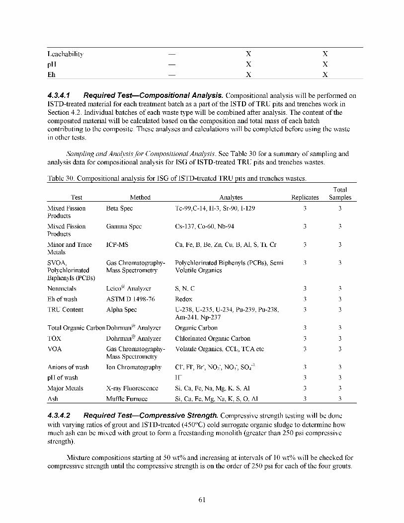
Leachability
PH Eh
X X X
X X X
4.3.4.7 ISTD-treated material for each treatment batch as a part of the ISTD of TRU pits and trenches work in Section 4.2. Individual batches of each waste type will be combined after analysis. The content of the composited material will be calculated based on the composition and total mass of each batch contributing to the composite. These analyses and calculations will be completed before using the waste in other tests.
Required Test-Compositions/ Analysis. Compositional analysis will be performed on
Sampling and Analysis for Compositional Analysis. See Table 30 for a summary of sampling and analysis data for compositional analysis for ISG of ISTD-treated TRU pits and trenches wastes.
Table 30. Compositional analvsis for ISG of ISTD-treated TRU pits and trenches wastes Total
Test Method Analytes Replicates Samples
Mixed Fission Beta Spec Products
Mixed Fission Gamma Spec Products
Minor and Trace ICP-MS Metals
SVOA, Gas Chromatography- Polychlorinated Mass Spectrometry Biphenyls (PCBs)
Nonmetals Leico@ Analyzer
Eh of wash ASTM D 1498-76
TRU Content Alpha Spec
Total Organic CarbonDohrman@ Analyzer
TOX Dohrman@ Analyzer
VOA Gas Chromatography-
Anions of wash Ion Chromatography
pH of wash
Major Metals X-ray Fluorescence
Mass Spectrometry
Tc-99,C-14, H-3, Sr-90,I-129
CS-137, CO-60, Nb-94
Ca, Fe, B, Be, Zn, Cu, B, Al, S, Ti, Cr
Polychlorinated Biphenyls (PCBs), Semi Volatile Organics
s, N, c Redox
Am-241, Np-237
Organic Carbon
Chlorinated Organic Carbon
Volatile Organics, CC14, TCA etc
U-238, U-235, U-234, Pu-239, Pu-238,
Cl-, Fl-, Br-, NO;, NO3-, SOi2
H+ Si, Ca, Fe, Na, Mg, K, S, A1
Ash
4.3.4.2 Required Test-Compressive Strength. Compressive strength testing will be done with varying ratios of grout and ISTD-treated (450°C) cold surrogate organic sludge to determine how much ash can be mixed with grout to form a freestanding monolith (greater than 250 psi compressive strength).
Muffle Furnace Si, Ca, Fe, Mg, Na, K, S, 0, A1
Mixture compositions starting at 50 wt% and increasing at intervals of 10 wt% will be checked for compressive strength until the compressive strength is on the order of 250 psi for each of the four grouts.
61
3 3
3 3
3 3
3 3
3 3
3 3
3 3
3 3
3 3
3 3
3 3
3 3
3 3 3 3
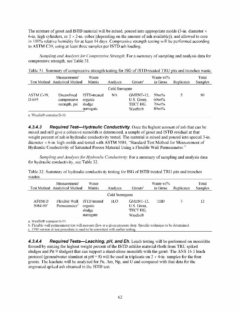
The mixture of grout and ISTD material will be mixed, poured into appropriate molds (3-in. diameter x 6-in. high cylinders, or 2 x 2-in. cubes [depending on the amount of ash available]), and allowed to cure in 100% relative humidity for at least 14 days. Compressive strength testing will be performed according to ASTM C39, using at least three samples per ISTD ash loading.
Sampling and Analysis for Compressive Strength. For a summary of sampling and analysis data for compressive strength, see Table 3 1.
Table 3 1. Summary of compressive strength testing for ISG of ISTD-treated TRU pits and trenches waste.
Test Method Analytical Method Matrix Analytes Grouts” in Grout Replicates Samples
Cold Surrogate
Measurement/ Waste Waste wt% Total
ASTM C-39, Unconfined ISTD-treated NA GMENT-12, 50wt% 5 80 D-695 compressive organic U.S. Grout, 60wt%
strength, psi sludge TECTHG, 70wt% surrogate Waxfix@ 8Owt%
a. WaxfixB contains B-10.
4.3.4.3 mixed and still give a cohesive monolith is determined, a sample of grout and ISTD residual at that weight percent of ash is hydraulic conductivity tested. The material is mixed and poured into special 3-in. diameter x 6-in. high molds and tested with ASTM 5084, “Standard Test Method for Measurement of Hydraulic Conductivity of Saturated Porous Material Using a Flexible Wall Permeameter.”
Required Test-Hydraulic Conductivity, Once the highest amount of ash that can be
Sampling and Analysis for Hydraulic Conductivity, For a summary of sampling and analysis data for hydraulic conductivity, see Table 32.
Table 32. Summary of hydraulic conductivity testing for ISG of ISTD treated TRU pits and trenches wastes.
Measurement/ Waste Waste wt% Total Test Method Analytical Method Matrix Analytes Grouts” in Grout Replicates Samples
Cold Surrogates
ASTM D Flexible Wall ISTD treated H20 GMENT-12, TBD 3 12 5084-90“ Permeameterb organic U.S. Grout,
sludge TECT HG, surrogate Waxfix@
a. WaxfixB contains B-10. b. Flexible wall permeameter test will measure flow at a given pressure drop. Specific technique to be determined. c. 1990 version of test procedure is used to be consistent with earlier testing.
4.3.4.4 formed by mixing the highest weight percent of the ISTD ashlike material (both from TRU spiked sludges and Pit 9 sludges) that can support a stand-alone monolith with the grout. The ANS 16.1 leach protocol (groundwater simulant at pH = 8) will be used in triplicate on 2 x 4-in. samples for the four grouts. The leachate will be analyzed for Pu, Am, Np, and U and compared with that data for the ungrouted spiked ash obtained in the ISTD test.
Required Tests-Leaching, pH, and Eh. Leach testing will be performed on monoliths
62
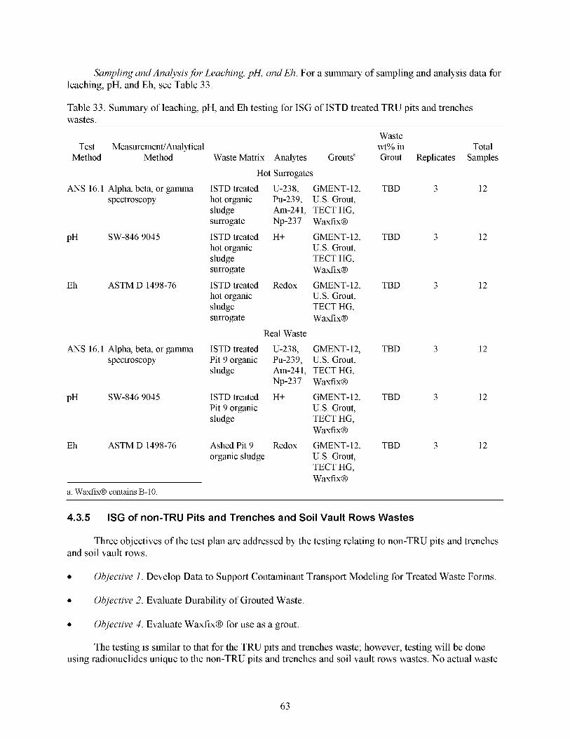
Sampling and Analysis for Leaching, pH, and Eh. For a summary of sampling and analysis data for leaching, pH, and Eh, see Table 3 3 .
Table 3 3 . Summary of leaching, pH, and Eh testing for ISG of ISTD treated TRU pits and trenches wastes.
Method Method Test Measurement/Analytical
-
ANS 16.1 Alpha, beta, or gamma spectroscopy
PH SW-846 9045
Eh ASTM D 1498-76
ANS 16.1 Alpha, beta, or gamma spectroscopy
PH SW-846 9045
Eh ASTM D 1498-76
Waste Matrix Analytes Grouts”
Hot Surrogates
ISTD treated U-238, GMENT-12, hot organic Pu-239, U.S. Grout, sludge Am-24 1, TECT HG, surrogate Np-237 Waxfix@
hot organic U.S. Grout, sludge TECT HG, surrogate Waxfix@
ISTD treated Redox GMENT-12, hot organic U.S. Grout, sludge TECT HG, surrogate Waxfix@
Real Waste
ISTD treated U-238, GMENT-12, Pit 9 organic Pu-239, U.S. Grout, sludge Am-24 1, TECT HG,
ISTD treated H+ GMENT- 12,
Np-237 Waxfix@
ISTD treated H+ GMENT- 12, Pit 9 organic U.S. Grout, sludge TECT HG,
Ashed Pit 9 Redox GMENT-12, organic sludge U.S. Grout,
TECT HG, Waxfix@
Waxfix@
a. WaxfixB contains B-10.
Waste wt% in Total Grout Replicates Samples
TBD 3 12
TBD
TBD
TBD
TBD
TBD
3 12
3 12
3 12
3 12
3 12
4.3.5 ISG of non-TRU Pits and Trenches and Soil Vault Rows Wastes
Three objectives of the test plan are addressed by the testing relating to non-TRU pits and trenches and soil vault rows.
Objective 1. Develop Data to Support Contaminant Transport Modeling for Treated Waste Forms.
0 Objective 2. Evaluate Durability of Grouted Waste.
0 Objective 4. Evaluate WaxfixB for use as a grout.
The testing is similar to that for the TRU pits and trenches waste; however, testing will be done using radionuclides unique to the non-TRU pits and trenches and soil vault rows wastes. No actual waste
63
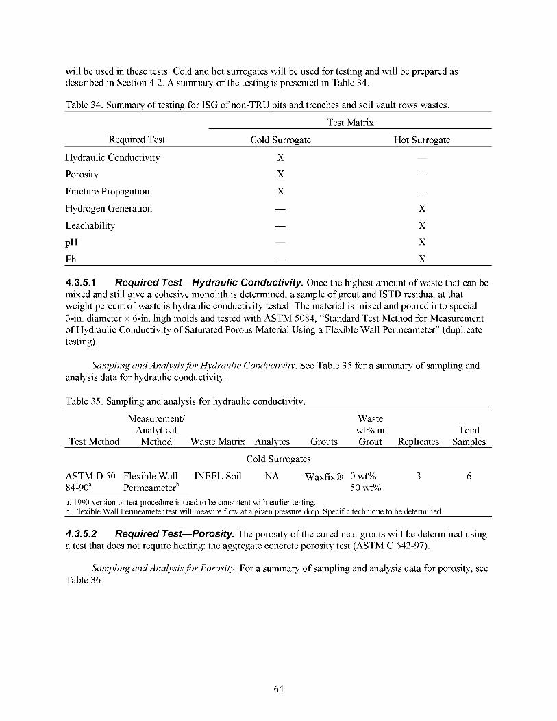
will be used in these tests. Cold and hot surrogates will be used for testing and will be prepared as described in Section 4.2. A summary of the testing is presented in Table 34.
Table 34. Summary of testing for ISG of non-TRU pits and trenches and soil vault rows wastes.
Test Matrix
Required Test Cold Surrogate Hot Surrogate
Hydraulic Conductivity X -
Porosity X -
Fracture Propagation X -
Hydrogen Generation X
Leachability X
PH X
-
-
-
- Eh X
4.3.5.1 mixed and still give a cohesive monolith is determined, a sample of grout and ISTD residual at that weight percent of waste is hydraulic conductivity tested. The material is mixed and poured into special 3-in. diameter x 6-in. high molds and tested with ASTM 5084, “Standard Test Method for Measurement of Hydraulic Conductivity of Saturated Porous Material Using a Flexible Wall Permeameter” (duplicate testing).
Required Test-Hydraulic Conductivity. Once the highest amount of waste that can be
Sampling and Analysis for Hydraulic Conductivity. See Table 35 for a summary of sampling and analysis data for hydraulic conductivity,
Table 35. Sampling and analysis for hydraulic conductivity,
Measurement/ Waste Analytical wt% in Total
Test Method Method Waste Matrix Analytes Grouts Grout Replicates Samples
Cold Surrogates
ASTM D 50 Flexible Wall INEEL Soil NA Waxfix@ O w t % 3 6 84-90” Permeameterb 50 wt%
a. 1990 version of test procedure is used to be consistent With earlier testing. b. Flexible Wall Permeameter test Will measure flow at a given pressure drop. Specific teclnnque to be determined.
4.3.5.2 a test that does not require heating: the aggregate concrete porosity test (ASTM C 642-97).
Required Test-Porosity. The porosity of the cured neat grouts will be determined using
Sampling and Analysis for Porosity. For a summary of sampling and analysis data for porosity, see Table 36.
64
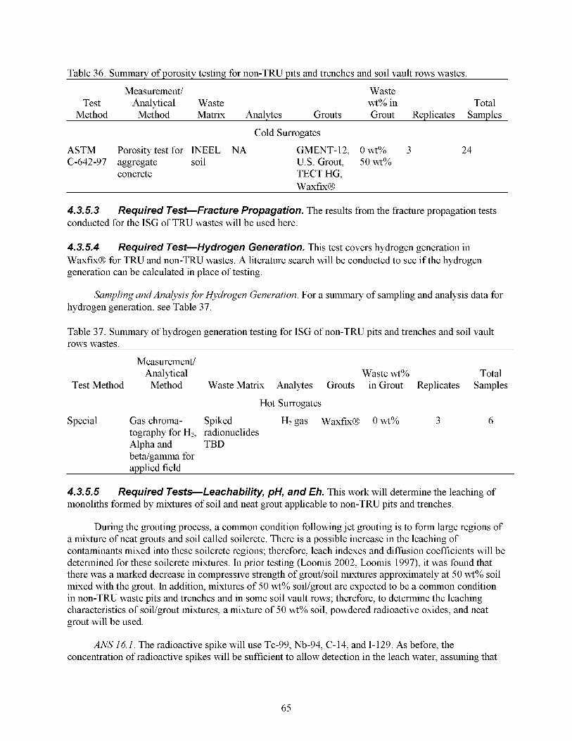
Table 36. Summarv of Dorositv testing for non-TRU Dits and trenches and soil vault rows wastes.
Measurement/ Waste Test Analytical Waste wt% in Total
Method Method Matrix Analytes Grouts Grout Replicates Samples
Cold Surrogates
ASTM Porosity test for INEEL NA GMENT-12, 0 wt% 3 24 C-642-97 aggregate soil U.S. Grout, 50 wt%
concrete TECT HG, WaxfixB
4.3.5.3 conducted for the ISG of TRU wastes will be used here.
Required Test-Fracture Propagation. The results from the fracture propagation tests
4.3.5.4 WaxfixB for TRU and non-TRU wastes. A literature search will be conducted to see if the hydrogen generation can be calculated in place of testing.
Required Test-Hydrogen Generation. This test covers hydrogen generation in
Sampling and Analysis for Hydrogen Generation. For a summary of sampling and analysis data for hydrogen generation, see Table 37.
Table 37. Summary of hydrogen generation testing for ISG of non-TRU pits and trenches and soil vault rows wastes.
Measurement/ Analytical Waste wt% Total
Test Method Method Waste Matrix Analytes Grouts in Grout Replicates Samples
Hot Surrogates
Special Gas chroma- Spiked H2gas WaxfixB O w t % 3 6 tography for H2, radionuclides Alpha and TBD beta/gamma for applied field
4.3.5.5 monoliths formed by mixtures of soil and neat grout applicable to non-TRU pits and trenches.
Required Tests-Leachability, pH, and Eh. This work will determine the leaching of
During the grouting process, a common condition following jet grouting is to form large regions of a mixture of neat grouts and soil called soilcrete. There is a possible increase in the leaching of contaminants mixed into these soilcrete regions; therefore, leach indexes and diffusion coefficients will be determined for these soilcrete mixtures. In prior testing (Loomis 2002, Loomis 1997), it was found that there was a marked decrease in compressive strength of grout/soil mixtures approximately at 50 wt% soil mixed with the grout. In addition, mixtures of 50 wt% soil/grout are expected to be a common condition in non-TRU waste pits and trenches and in some soil vault rows; therefore, to determine the leaching characteristics of soil/grout mixtures, a mixture of 50 wt% soil, powdered radioactive oxides, and neat grout will be used.
ANS 16.1. The radioactive spike will use Tc-99, Nb-94, C-14, and 1-129. As before, the concentration of radioactive spikes will be sufficient to allow detection in the leach water, assuming that
65

the leach index varies between 8 and 12. The sample material will be poured into 2-in. diameter by 4-in. high molds (triplicates) and allowed to cure for 14 days. As with all leach testing, a groundwater simulant will be used to mimic the water found in the SDA with a pH of 8 used in the procedure. Eh and pH of the leachate will be measured during the ANS 16.1 procedure.
Sampling and Analysis for Leaching, pH, and Eh. For a summary of sampling and analysis data for leaching, pH, and Eh, see Table 38.
Table 3 8. Summary of leachability, pH, and Eh testing for ISG of non-TRU pits and trenches and soil vault rows waste.
Measurement/ Waste Analytical wt% in Total
Test Method Method Waste Matrix Analytes Grouts Grout Replicates Samples
Hot Surrogates
ANS 16.1 Beta INEEL soil Tc-99,C-14, GMENT-12, 0 wt% 3 24 spectroscopy Nb-94,I-129 U.S. Grout, 50 wt%
TECT HG, Waxfix@
U.S. Grout, 50 wt% TECT HG, Waxfix@
PH ASTM D1293 INEEL soil H+ GMENT-12, O w t % 3 24
Eh ASTM D INEEL Redox GMENT-12, O w t % 3 24 1498-76 soil U.S. Grout, 50 wt%
TECT HG, Waxfix@
4.4 Ex Situ Grouting
Ex situ grouting (solidification) is being considered for treatment of the Pad A salt waste. Ex situ grouting would include selection of an appropriate grout and the design of an approach to transfer the waste from Pad A to a mixing system where existing containers could be opened, the waste contents mixed with grout, and the mix placed in containers for disposal. This test plan addresses the selection of an appropriate grout for the stabilization of Pad A salt waste.
Two objectives of this test plan are addressed by ESG solidification of salt evaluation as follows:
0 Objective 1. Estimate the potential for the release of contaminants from the final waste form.
0 Objective 2. Evaluate the durability of grouthalt waste forms
Three candidate grouts have been identified for testing: polysiloxane, Saltstone, and WaxfixB. Di-methyl polysiloxane marketed by Technologies Vision Group uses a polymer encapsulation technology (Loomis 1997) shown to successhlly encapsulate surrogate salt materials. Saltstone grout developed by Savannah fiver has also been developed for salt encapsulation. WaxfixB has been described above in the in situ portion of the test plan. A brief description and formulation for each of the grouts is shown in Table 39.
66
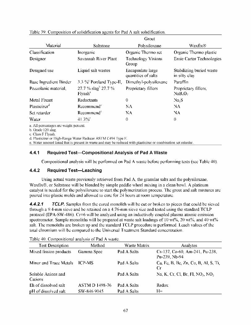
Table 39. Composition of solidification agents for Pad A salt solidification. Grout
Material Saltstone Polysiloxane WaxfixB Classification Inorganic Organic Thermo set Organic Thermo plastic Designer Savannah fiver Plant Technology Visions Ernie Carter Technologies
Designed use Liquid salt wastes Encapsulate large Stabilizing buried waste
Base Ingredient Binder 3.3 %" Portland Type-11, Dimethyl-polysiloxane Paraffin Pozzolanic material, 27.7 % slagb 27.7 % Proprietary fillers Proprietary fillers,
Flyash' NaB407 Metal Fixant Reductants 0 Na2S Plasticizerd Recommend" NA NA Set retarder Recommend" NA NA Water 41.3%" 0 0
Group
quantities of salts in silty clay
a. All percentages are weight percent. b. Grade 120 slag. c. Class F Flyash. d. Plasticizer or Kgh-Range Water Reducer ASTM C494 Type F. e. Water amount listed that is present in waste and may be reduced with plasticizer or combination set retarder.
4.4.1 Required Test-Compositional Analysis of Pad A Waste
Compositional analysis will be performed on Pad A waste before performing tests (see Table 40).
4.4.2 Required Test-Leac h i ng
Using actual waste previously retrieved from Pad A, the granular salts and the polysiloxane, WaxfixB, or Saltstone will be blended by simple paddle wheel mixing in a clean bowl. A platinum catalyst is needed for the polysiloxane to start the polymerization process. The grout and salt mixtures are poured into plastic molds and allowed to cure for 24 hours at room temperature.
4.4.2.7 through a 9.4-mm sieve and be retained on a 4.76-mm sieve size and tested using the standard TCLP protocol (EPA-SW-486). Cr+6 will be analyzed using an inductively coupled plasma atomic emission spectrometer. Sample monoliths will be prepared at waste salt loadings of 10 wt%, 20 wt%, and 40 wt% salt. The monoliths are broken up and the standard TCLP procedure is performed. Leach values of the total chromium will be compared to the Universal Treatment Standard concentration.
Table 40. Compositional analysis of Pad A waste.
Mixed fission products Gamma Spec Pad A Salts Cs-137, Co-60, Am-241, Pu-238,
Minor and Trace Metals ICP-MS
Soluble Anions and Cations Eh of dissolved salt ASTM D 1498-76 Pad A Salts Redox
TCLP. Samples from the cured monolith will be cut or broken to pieces that could be sieved
Test Description Method Waste Matrix Analytes
PU-239, Nb-94 Pad A Salts
Pad A Salts
Ca, Fe, B, Be, Zn, Cu, B, Al, S, Ti, Cr Na, K, Cr, C1, Br, F1, NOs, NO2
pH of dissolved salt SW-846 9045 Pad A Salts H+
67
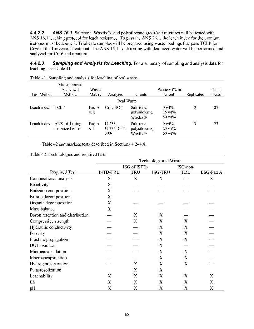
4.4.2.2 ANS 16.1 leaching protocol for leach resistance. To pass the ANS 26.1, the leach index for the uranium isotopes must be above 8. Triplicate samples will be prepared using waste loadings that pass TCLP for Cr+6 at the Universal Treatment. The ANS 16.1 leach testing with deionized water will be performed and analyzed for Cr+6 and uranium.
ANS 76.7. Saltstone, WaxfixB, and polysiloxane grouthalt mixtures will be tested with
4.4.2.3 leaching, see Table 4 1.
Table 4 1. Sampling and analysis for leaching of real waste.
Sampling and Analysis for Leaching. For a summary of sampling and analysis data for
Measurement/ Analytical Waste Waste wt% in Total
Test Method Method Matrix Analytes Grouts Grout Replicates Tests
Real Waste Leach index TCLP Pad A Crffi, NO3- Saltstone, 0 wt% 3 27
salt polysiloxane, 25 wt% Waxfix@ 50 wt%
deionized water salt U-235, Cr+6, polysiloxane, 25 wt% NO3- Waxfix@ 50 wt%
Leach index ANS 16.1 using Pad A U-238, Saltstone, 0 wt% 3 27
Table 42 summarizes tests described in Sections 4.2-4.4.
Table 42. Technologies and required tests. Technology and Waste
ISG of ISTD- ISG-non- Reauired Test ISTD-TRU TRU ISG-TRU TRU ESG-PadA
- Compositional analysis X X X X Reactivity X - - - -
Emission composition X - - - -
Nitrate decomposition X - - - -
Organic decomposition X - - - -
Mass balance X - - -
Boron retention and distribution X X - -
-
-
- Compressive strength X X X -
Hydraulic conductivity X X -
Porosity X X -
Fracture propagation X X -
Microencapsulation X X -
Macroencapsulation X X -
Hydrogen generation X X X -
Leachability X X X X X
PH X X X X X
- -
- -
- -
- - DOT oxidizer X - -
- -
- -
-
- Pu aerosolization X X - -
Eh X X X X X
68
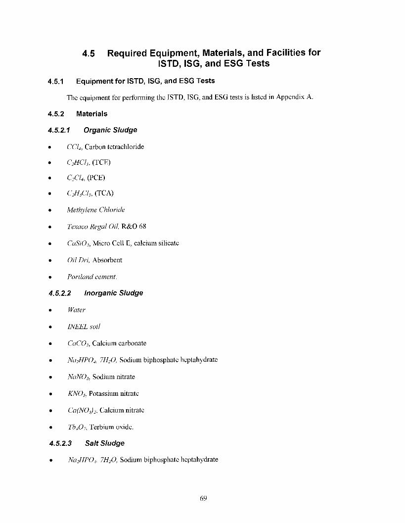
4.5 Required Equipment, Materials, and Facilities for ISTD, ISG, and ESG Tests
4.5.1 Equipment for ISTD, ISG, and ESG Tests
The equipment for performing the ISTD, ISG, and ESG tests is listed in Appendix A.
4.5.2 Materials
4.5.2.1 Organic Sludge
CCl,, Carbon tetrachloride
c2Hcl3, (TCE)
c2Cl4, (PCE)
c2H3c13, (TCA)
Methylene Chloride
Oil Dri, Absorbent
Portland cement.
4.5.2.2 Inorganic Sludge
0 Wuter
INEEL soil
CuC03, Calcium carbonate
NuN03, Sodium nitrate
&TO3, Potassium nitrate
Cu(NO3)2, Calcium nitrate
Tb407, Terbium oxide.
4.5.2.3 Salt Sludge
Texuco Regal Oil, R&O 68
CuSi03, Micro Cell E, calcium silicate
Nu2HP04, 7H20, Sodium biphosphate heptahydrate
Nu2HP04, 7H20, Sodium biphosphate heptahydrate
69
NuNOj, Sodium nitrate
NuCl. Sodium chloride
Nu2S04, Sodium sulfate
KN03, Potassium nitrate
Cl~ l6N208 , EDTA
NuHCOj, Sodium bicarbonate
NuF, Sodium fluoride
NuN02, Sodium nitrite.
4.5.2.4 Low-Level Waste Surrogates ISG
Portland cement
INEEL soil
Metal chips.
4.5.2.5 ISG Grouts
GMENT-12
U S . Grout
TECTHG
WUXJiXB.
4.5.2.6 ESG Grouts
Sultstone
Polysiloxune
WUXJiXB.
4.5.2.7 ISG
Rare-Earth and TRU Spike Contaminants for Surrogate Wastes for ISTD and
Tb407, Terbium oxide
Tb(N03),, Terbium nitrate (solution)
Ce203, Cerium oxide
Ce(N03)3, Cerium nitrate (solution)
70
0 Pu(N03),, Plutonium nitrate (solution)
NP(NO~)~, Neptunium nitrate (solution)
0 U(N03)6, Uranium nitrate (solution)
0 Am(N03)3, Americium nitrate (solution)
U, Uranium oxide (powder)
Np, Neptunium oxides (powder)
0 Pu, Plutonium oxide (powder)
0 Am, Americium oxide (powder).
4.5.3 Laboratory Facilities
Both radiological and nonradiological materials and facilities will be required. The bench facilities to be used will be based on the type of material tested and tests performed. Radiological samples will be handled in approved radiological areas (Test Reactor Area or INTEC), nonradiological tests in the IRC-High Bay area. Standard characterizations will be performed in outside vendor laboratories. All instruments will be calibrated and maintained according to the manufacturer’s recommendation. The INEEL calibration group calibrates all balances on a yearly basis using external National Institute of Standards and Technologies traceable weights. The required chemicals for the bench ISTD study matrices, surrogates, and spikes are listed in Section 4.6.2. Surrogate chemicals can be technical grade.
At the conclusion of the bench testing on SDA waste samples and radiologically spiked samples, the equipment, hoods, and vessels used to heat contaminated samples will be cleaned using the procedures in the Laboratory Radiological Control Manual. Following decontamination, representative surface wipe samples will be collected and analyzed by a radiological control technician for total alpha and beta-gamma. Results will be reported to the site radiological control officer. Based on the results of wipe samples, equipment may be released from the site by the radiological control officer.
4.5.4 Laboratory Reactivity and Off-Gas Measurements
For laboratory-scale reactivity and off-gas measurements, a standard tube hrnace will be used to heat nitrate and nitrate organic mixtures at a slow rate of about 10°C per hour. A tube hrnace (such as a Thermolyne or Lindberg/Blue M), flow meters, and gas analysis instruments, and Type-K thermocouples (such as those from Omega Engineering calibrated at the factory) are used. Temperature readout and control on the hrnace are by solid-state control and thermocouple.
Off-gas will be monitored with laboratory NO, and GC analysis augmented by an industrial combustion gas monitoring system and by trapping gases in water for Ion Chromatography analysis. For larger scale tests, larger quantities of surrogate sludges (up to 55 gal) will be heated with a central well heater of the same design used in h l l scale.
Temperature data are collected by computer using a data logging system such as IOtech Dynares input/output interface board connected to a thermocouple (TC) terminal panel. This computer controls the rate of heating with software such as Strawberry Tree commercial software (IOtecWStrawberry Tree
71
1996). These data are collected using Workbench for Windows software (IOtecWStrawberry Tree 1996) at 100 Hz.
Standard laboratory equipment will be required, such as an analytical balance, drying oven, muffle hrnace, pH meter, glassware, inert leach vessels, and off-gas samplers. Standard analytical instrumentation will also be required.
For DOT oxidizer testing on WaxfixB, the same salt surrogate used in the reactivity test, (NaN03 and KN03 blended in an approximate 2: 1 ratio), will be used. Additionally, carbon tetrachloride adsorbed on soil or absorbent will be used as a surrogate for 743 organic sludges and carbon tetrachloride in the soil. The mixtures for surrogate sludges will be made in bulk sufficient for lab-, bench-, and engineering-scale testing.
4.6 Contingency
The final phase of both ISTD and ISG bench testing depends on the availability of radiological waste samples from the currently planned Glovebox Excavator Method retrieval demonstration in Pit 9. The quantity and composition of the waste samples will not be known until the Glovebox Excavator Method project obtains the samples and the analysis of the samples is completed. The test plan is based on best current knowledge, but may need to be adjusted to accommodate the type of sample material available (for example, there is a small chance that no organic sludge drums are encountered during the excavation).
The drum-scale reactivity testing will use only cold surrogates to minimize safety concerns and simplify locating an appropriate testing facility and does not depend on the samples from the Glovebox Excavator Method excavation. The current plan depends on hnding and securing a vendor (such as the Energetic Materials Research and Testing Center [EMRTC]) that can do this specialized type of testing.
Actual RFP nitrate salts have already been retrieved and are available for nitrate decomposition and grout encapsulation testing independent of the Glovebox Excavator Method activities. All of the tests using cold or hot surrogates can also be performed independent of the Glovebox Excavator Method activities.
Effectiveness of radiological fixation results without SDA samples will be of limited value, but can indicate whether heating of waste solids will alter leach resistance. The type of solid sample material obtained might change the experimental design. Only contaminated sludges and soil will be sampled in the Glovebox Excavator Method retrieval. Organic and salt sludges will be discretely sampled. All will be characterized per the Resource Conservation and Recovery Act for compliant storage. Limited samples will be available for subsequent characterization and treatability studies (Salomon 2002).
72