terex rough terrain crane rt780 data sheet · rough terrain crane rt 780 datasheet - imperial...
TRANSCRIPT

RT 780
ROUGH TERRAIN CRANE RT 780
DATASHEET - IMPERIAL
Features:
�Rated�capacity:�80�ton�@�10�ft�working�radius
�Maximum�boom�length:�126�ft�
Maximum�tip�height:�190�ft

2
RT 780CONTENTS
Key� . . . . . . . . . . . . . . . . . . . . . . . . . . . . . . . . . . . . . . . . . . . . . . . . . . . . . . . . . . . . . . . . . . . . . . . . . . . . . . . . . . . . . . . . . . . 3
DimensionsCrane dimensions�. . . . . . . . . . . . . . . . . . . . . . . . . . . . . . . . . . . . . . . . . . . . . . . . . . . . . . . . . . . . . . . . . . . . . . . . . . . 4Crane weights� . . . . . . . . . . . . . . . . . . . . . . . . . . . . . . . . . . . . . . . . . . . . . . . . . . . . . . . . . . . . . . . . . . . . . . . . . . . . . . 5
Load chartsRange Diagram – Main Boom – Outriggers fully extended (100%) �. . . . . . . . . . . . . . . . . . . . . . . . . . . . . . . . . 6Load Chart – Main Boom – Outriggers fully extended (100%)� . . . . . . . . . . . . . . . . . . . . . . . . . . . . . . . . . . . . . 7Range Diagram – Main Boom – Outriggers fully retracted (0%)�. . . . . . . . . . . . . . . . . . . . . . . . . . . . . . . . . . . . 8Load Chart – Main Boom – Outriggers fully retracted (0%� . . . . . . . . . . . . . . . . . . . . . . . . . . . . . . . . . . . . . . . . 9Range Diagram – Main Boom – 33 ft offsettable jib�. . . . . . . . . . . . . . . . . . . . . . . . . . . . . . . . . . . . . . . . . . . . . 10Load Chart – Main Boom – 33 ft offsettable jib�. . . . . . . . . . . . . . . . . . . . . . . . . . . . . . . . . . . . . . . . . . . . . . . . . 11Range Diagram – Main Boom – 57 ft offsettable jib�. . . . . . . . . . . . . . . . . . . . . . . . . . . . . . . . . . . . . . . . . . . . . 12Load Chart – Main Boom – 57 ft offsettable jib�. . . . . . . . . . . . . . . . . . . . . . . . . . . . . . . . . . . . . . . . . . . . . . . . . 13Range Diagram – Main Boom – On tires�. . . . . . . . . . . . . . . . . . . . . . . . . . . . . . . . . . . . . . . . . . . . . . . . . . . . . . . 14Load Chart – Main Boom – On tires�. . . . . . . . . . . . . . . . . . . . . . . . . . . . . . . . . . . . . . . . . . . . . . . . . . . . . . . . . . . 15
Technical descriptionBoom�. . . . . . . . . . . . . . . . . . . . . . . . . . . . . . . . . . . . . . . . . . . . . . . . . . . . . . . . . . . . . . . . . . . . . . . . . . . . . . . . . . . . . 16Hoist, rope and hook. . . . . . . . . . . . . . . . . . . . . . . . . . . . . . . . . . . . . . . . . . . . . . . . . . . . . . . . . . . . . . . . . . . . . 16,�17Superstructure�. . . . . . . . . . . . . . . . . . . . . . . . . . . . . . . . . . . . . . . . . . . . . . . . . . . . . . . . . . . . . . . . . . . . . . . . . . . . . 17Cab, controls, operator aids and load limiter / load indicator� . . . . . . . . . . . . . . . . . . . . . . . . . . . . . . . . . 17,18Carrier, engine, drive-line and hydraulic system�. . . . . . . . . . . . . . . . . . . . . . . . . . . . . . . . . . . . . . . . . . . . . . . . 18Vehicle performance�. . . . . . . . . . . . . . . . . . . . . . . . . . . . . . . . . . . . . . . . . . . . . . . . . . . . . . . . . . . . . . . . . . . . . . . . 19Tires�. . . . . . . . . . . . . . . . . . . . . . . . . . . . . . . . . . . . . . . . . . . . . . . . . . . . . . . . . . . . . . . . . . . . . . . . . . . . . . . . . . . . . . 19
Page:

3
RT 780KEYKEY
General�performance
Telescoping�mode
Boom�luffing�angle
Working�radius
Max.�boom�length�with�extension
Distance�from�the�hook�to�the�head�sheave�pin
Slewing�locked�/�Slewing�locked�at�specified�position
Slewing�gears
Lifting�on�wheels�/�Pick�&�Carry
Auxiliary�hoist�
Rope�length�
Max.�line�pull�
Tire�
Controls�
Engine�
Steering�
Speed�
Heating�/�Air�conditioning�
Gradeability�
Gross�vehicle�weight
Weight�on�front�axle
Weight�on�rear�axle
Counterweight
Main�boom
Boom�length
Tip�height
Boom�with�extension
Main�boom�with�aux�head
Slewing�/�Allowable�slewing�range
Slewing�brake
Outriggers�/�Lifting�on�outriggers�(100/50/0%�extended)
Main�hoist
Hoist�speed
Rope�–�Standard�/�Optional
Rope�diameter
Hook�block
Cab
Operator�aids�/�Load�limiter�/�Load�indicator
Mechanical�transmission
Hydraulics
Working�temperature
Lights
Crane�/�Crane�in�standard�configuration
Crane�without�counterweight
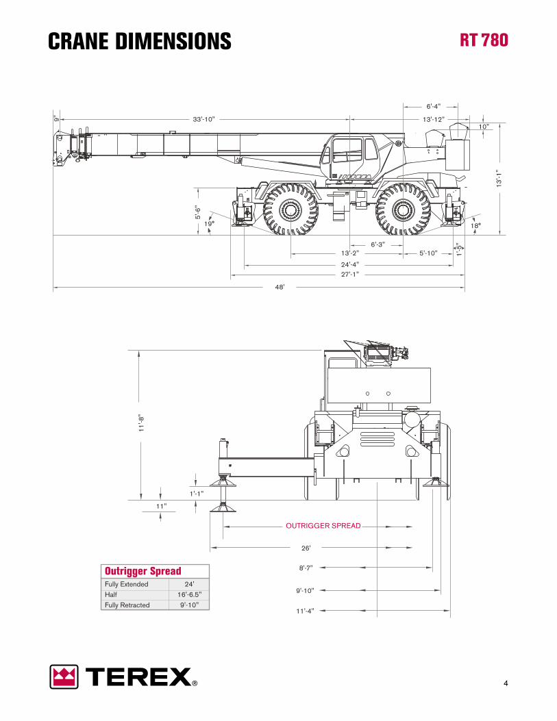
Outrigger Spread Fully Extended 24'Half 16'-6.5"Fully Retracted 9'-10"
OUTRIGGER SPREAD
13'-2" 5'-10"
24'-4"
1'-5
"
27'-1"
26'
8'-7"
9'-10"
11'-4"
19°
1'-1"
11"
11'-8
"
18°
13'-1
"
10"
6'-3"
13'-12"33'-10" 9"
48'
6'-4"
5'-6
"
4
RT 780CRANE DIMENSIONS

5
RT 780CRANE WEIGHTSApproximate Weights
NOTE:�Values�are�subject�to�2%�variation�
*� Weight�includes�rope
STD� 91,216�lb� 47,047�lb� 44,169�lb
Add�/�Subtract�for�main�optional�equipment
� 33�ft�to�57�ft�swing�on�jib�stowed� +�2,170��lb� +�3,992�lb� –�1,822�lb
� Auxiliary�boom�head� +�125�lb� +�406�lb� –��281�lb
� Auxiliary�hoist*� +�134�lb� –�35�lb� +�159�lb
� 5�sheaves,�75T� +�1,608�lb� +�3,447�lb� –��1,839�lb�
� 5�sheaves,�60T� +�1,204�lb� +�2,581�lb� –�1,377�lb

170 ft160 ft150 ft140 ft130 ft120 ft110 ft100 ft90 ft80 ft70 ft60 ft50 ft40 ft30 ft20 ft10 ftft
170 ft
160 ft
150 ft
140 ft
130 ft
120 ft
110 ft
100 ft
90 ft
80 ft
200 ft
190 ft
180 ft
70 ft
60 ft
50 ft
40 ft
30 ft
20 ft
10 ft
40 f t
90 f t
102 f t
114 f t
126 f t
54 f t
66 f t
78 f t
70°
78°
60°
50°
40°
30°
20°
10°
6
RT 780
with�hook�block:6�ft�9�in
RANGE DIAGRAM - MAIN BOOMOutriggers Fully Extended (100%)
7
RT 780
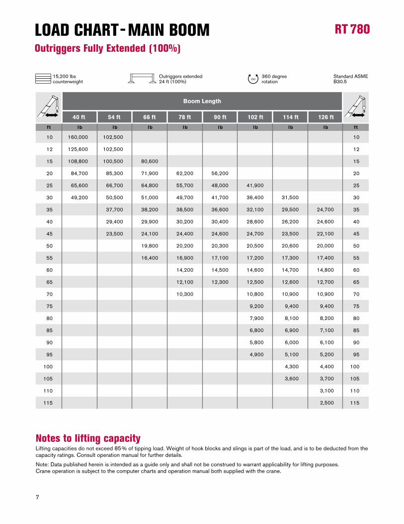
Notes to lifting capacity Lifting�capacities�do�not�exceed�85%�of�tipping�load.�Weight�of�hook�blocks�and�slings�is�part�of�the�load,�and�is�to�be�deducted�from�the�capacity�ratings.�Consult�operation�manual�for�further�details.
Note:�Data�published�herein�is�intended�as�a�guide�only�and�shall�not�be�construed�to�warrant�applicability�for�lifting�purposes.��Crane�operation�is�subject�to�the�computer�charts�and�operation�manual�both�supplied�with�the�crane.
LOAD CHART - MAIN BOOMOutriggers Fully Extended (100%)
ftft lb lb lb lb lb lb lb lb
40 ft 54 ft 66 ft 78 ft 90 ft 102 ft 114 ft 126 ft
Boom Length
10
12
15
20
25
30
35
40
45
50
55
60
65
70
75
80
85
90
95
100
105
110
115
10
12
15
20
25
30
35
40
45
50
55
60
65
70
75
80
85
90
95
100
105
110
115
�160,000�
�125,600�
�108,800�
�84,700�
�65,600�
�49,200���
�102,500�
�102,500�
�100,500�
�85,300�
�66,700�
�50,500�
�37,700�
�29,400�
�23,500�
�80,600�
�71,900�
�64,800�
�51,000�
�38,200�
�29,900�
�24,100�
�19,800�
�16,400��
�62,200�
�55,700�
�49,700�
�38,500�
�30,200�
�24,400�
�20,200�
�16,900�
�14,200�
�12,100�
�10,300���
�56,200�
�48,000�
�41,700�
�36,600�
�30,400�
�24,600�
�20,300�
�17,100�
�14,500�
�12,300���
�41,900�
�36,400�
�32,100�
�28,600�
�24,700�
�20,500�
�17,200�
�14,600�
�12,500�
�10,800�
�9,200�
�7,900�
�6,800�
�5,800�
�4,900�
�31,500�
�29,500�
�26,200�
�23,500�
�20,600�
�17,300�
�14,700�
�12,600�
�10,900�
�9,400�
�8,100�
�6,900�
�6,000�
�5,100�
�4,300�
�3,600�
�24,700�
�24,600�
�22,100�
�20,000�
�17,400�
�14,800�
�12,700�
�10,900�
�9,400�
�8,200�
�7,100�
�6,100�
�5,200�
�4,400�
�3,700�
�3,100�
�2,500�
�
15,200�lbscounterweight
360�degree�rotation
Standard�ASME��B30.5
Outriggers�extended24�ft�(100%)

170 ft160 ft150 ft140 ft130 ft120 ft110 ft100 ft90 ft80 ft70 ft60 ft50 ft40 ft30 ft20 ft10 ftft 200 ft190 ft180 ft
170 ft
160 ft
150 ft
140 ft
130 ft
120 ft
110 ft
100 ft
90 ft
80 ft
200 ft
190 ft
180 ft
70 ft
60 ft
50 ft
40 ft
30 ft
20 ft
10 ft
40 f t
90 f t
102 f t
114 f t
126 f t
54 f t
66 f t
78 f t
70°
78°
60°
50°
40°
30°
20°
10°
45 FT BEGINNING OF OVER 360º EXTRA-CAUTION ZONE
8
RT 780
with�hook�block:6�ft�9�in
RANGE DIAGRAM - MAIN BOOMOutriggers Fully Retracted (0%)

9
RT 780LOAD CHART - MAIN BOOMOutriggers Fully Retracted (0%)
Notes to lifting capacity Lifting�capacities�do�not�exceed�85%�of�tipping�load.�Weight�of�hook�blocks�and�slings�is�part�of�the�load,�and�is�to�be�deducted�from�the�capacity�ratings.�Consult�operation�manual�for�further�details.
Note:�Data�published�herein�is�intended�as�a�guide�only�and�shall�not�be�construed�to�warrant�applicability�for�lifting�purposes.��Crane�operation�is�subject�to�the�computer�charts�and�operation�manual�both�supplied�with�the�crane.
ftft lb lb lb lb lb lb lb lb
40 ft 54 ft 66 ft 78 ft 90 ft 102 ft 114 ft 126 ft
Boom Length
10
12
15
20
25
30
35
40
45
50
10
12
15
20
25
30
35
40
45
50
�84,500�
�59,300�
�39,300�
�23,200�
�14,900�
�9,800����
�85,600�
�60,300�
�40,400�
�24,300�
�16,000�
�10,900�
�7,500�
�5,000�
�3,200��
�40,800�
�24,800�
�16,500�
�11,400�
�8,000�
�5,600�
�3,700��
�25,000�
�16,800�
�11,800�
�8,400�
�5,900�
�4,000����
�25,200�
�17,000�
�12,000�
�8,600�
�6,100�
�4,300����
�17,000�
�12,000�
�8,600�
�6,100�
�4,300��
�12,100�
�8,800�
�6,300�
�4,500�
�3,000�
�8,900�
�6,500�
�4,700�
�3,300�
�15,200�lbscounterweight
360�degree�rotation
Standard�ASME��B30.5
Outriggers�retracted9�ft�10�in�(0%)

170 ft160 ft150 ft140 ft130 ft120 ft110 ft100 ft90 ft80 ft70 ft60 ft50 ft40 ft30 ft20 ft10 ftft
170 ft
160 ft
150 ft
140 ft
130 ft
120 ft
110 ft
100 ft
90 ft
80 ft
200 ft
190 ft
180 ft
70 ft
60 ft
50 ft
40 ft
30 ft
20 ft
10 ft
40 f t
90 f t
102 f t
114 f t
126 f t
54 f t
66 f t
78 f t
159 f t
70°
78°
60°
50°
40°
30°
20°
10°
30°15°
BEGINNING OF OVER FRONT EXTRA-CAUTION ZONE 135 FT
BEGINNING OF OVER 360º EXTRA-CAUTION ZONE 132 FT
10
RT 780
with�hook�block:6�ft�9�in
RANGE DIAGRAM - MAIN BOOMWith Jib, 33 ft offset

11
RT 780LOAD CHART - MAIN BOOMWith Jib, 33 ft offset
Notes to lifting capacity Lifting�capacities�do�not�exceed�85%�of�tipping�load.�Weight�of�hook�blocks�and�slings�is�part�of�the�load,�and�is�to�be�deducted�from�the�capacity�ratings.�Consult�operation�manual�for�further�details.
Note:�Data�published�herein�is�intended�as�a�guide�only�and�shall�not�be�construed�to�warrant�applicability�for�lifting�purposes.��Crane�operation�is�subject�to�the�computer�charts�and�operation�manual�both�supplied�with�the�crane.
lbs lbs lbs
0° Offset 30° Offset15° Offset
Radius (ft)
Radius (ft)
Radius (ft)
33 ft Offsettable Jib
41
47
52
58
66
74
81
88
97
105
113
120
127
135
50
56
61
67
74
81
88
95
103
111
117
124
131
138
57
62
67
72
79
86
93
99
107
114
120
126
132
138
�12,500�
�12,000�
�11,500�
�10,900�
�9,900�
�9,200�
�8,600�
�7,300�
�5,700�
�4,500�
�3,600�
�2,900�
�2,200�
�1,600
�8,500�
�8,100�
�7,800�
�7,500�
�7,100�
�6,700�
�6,400�
�6,200�
�5,200�
�4,200�
�3,400�
�2,700�
�2,000�
�1,400����
�6,400�
�6,200�
�6,100�
�5,900�
�5,900�
�5,600�
�5,400�
�5,300�
�5,200�
�4,300�
�3,500�
�2,800�
�1,900�
�1,100��
� �
15,200�lbscounterweight
360�degree�rotation
Standard�ASME��B30.5
Outriggers�extended24�ft�(100%)

170 ft160 ft150 ft140 ft130 ft120 ft110 ft100 ft90 ft80 ft70 ft60 ft50 ft40 ft30 ft20 ft10 ftft 200 ft190 ft180 ft
170 ft
160 ft
150 ft
140 ft
130 ft
120 ft
110 ft
100 ft
90 ft
80 ft
200 ft
190 ft
180 ft
70 ft
60 ft
50 ft
40 ft
30 ft
20 ft
10 ft
40 f t
90 f t
102 f t
114 f t
126 f t
54 f t
66 f t
78 f t
182 f t
BEGINNING OF OVER 360º EXTRA-CAUTION ZONE 148 FT
BEGINNING OF OVER FRONT EXTRA-CAUTION ZONE 151 FT
78°
70°
60°
50°
40°
30°
20°
15°
10°
12
RT 780
with�hook�block:6�ft�9�in
RANGE DIAGRAM - MAIN BOOMWith Jib, 57 ft offset

13
RT 780LOAD CHART - MAIN BOOMWith Jib, 57 ft offset
Notes to lifting capacity Lifting�capacities�do�not�exceed�85%�of�tipping�load.�Weight�of�hook�blocks�and�slings�is�part�of�the�load,�and�is�to�be�deducted�from�the�capacity�ratings.�Consult�operation�manual�for�further�details.
Note:�Data�published�herein�is�intended�as�a�guide�only�and�shall�not�be�construed�to�warrant�applicability�for�lifting�purposes.��Crane�operation�is�subject�to�the�computer�charts�and�operation�manual�both�supplied�with�the�crane.
lbs lbs lbs
0° Offset 30° Offset15° Offset
Radius (ft)
Radius (ft)
Radius (ft)
57 ft Offsettable Jib
48
56
63
70
80
90
98
106
116
125
133
140
148
157
66
72
77
83
91
99
106
114
123
132
140
147
154
161
75
81
87
92
100
108
115
121
129
137
143
149
155
162
�6,500�
�6,400�
�6,200�
�6,000�
�5,400�
�4,900�
�4,500�
�4,200�
�3,800�
�3,500�
�2,800�
�2,200�
�1,600�
�1,000
�4,500�
�4,300�
�4,100�
�3,900�
�3,700�
�3,500�
�3,300�
�3,100�
�2,900�
�2,800�
�2,600�
�2,100�
�1,500�
�1,000
�3,300�
�3,200�
�3,100�
�3,000�
�2,900�
�2,800�
�2,700�
�2,600�
�2,500�
�2,500�
�2,400�
�2,000�
�1,500�
�1,000
� �15,200�lbscounterweight
360�degree�rotation
Standard�ASME��B30.5
Outriggers�extended24�ft�(100%)
� �

170 ft160 ft150 ft140 ft130 ft120 ft110 ft100 ft90 ft80 ft70 ft60 ft50 ft40 ft30 ft20 ft10 ftft
170 ft
160 ft
150 ft
140 ft
130 ft
120 ft
110 ft
100 ft
90 ft
80 ft
200 ft
190 ft
180 ft
70 ft
60 ft
50 ft
40 ft
30 ft
20 ft
10 ft
40 f t
54 f t
66 f t
78 f t
90 f t70°
78°
60°
50°
40°
30°
20°
10°0°10°1
0°20°2202
30°30
0°060°0
4
6
0°40°
0°50°5
0°70°7
78°78
0°10
0°202
0°30
0°4
0°5
0°06
70°7
878
14
RT 780
with�hook�block:6�ft�9�in
RANGE DIAGRAM - MAIN BOOMOn Tires

15
RT 780LOAD CHART - MAIN BOOMOn Tires
Notes to lifting capacity Lifting�capacities�do�not�exceed�75%�of�tipping�load.�Weight�of�hook�blocks�and�slings�is�part�of�the�load,�and�is�to�be�deducted�from�the�capacity�ratings.�Consult�operation�manual�for�further�details.
Note:�Data�published�herein�is�intended�as�a�guide�only�and�shall�not�be�construed�to�warrant�applicability�for�lifting�purposes.��Crane�operation�is�subject�to�the�computer�charts�and�operation�manual�both�supplied�with�the�crane.
0 mph Creep 2.5 mph
Boom Travel Speed Boom straight over front
Radius Length
ft ft lb lb lb
40
40
40
40
54
54
54
66
66
66
78
78
78
90
90
90
10
12
15
20
25
30
35
40
45
50
55
60
65
70
75
80
�82,700�
�69,800�
�54,200�
�36,000�
�24,900�
�18,200�
�14,200�
�11,600�
�9,600�
�7,900�
�6,300�
�4,900�
�3,300�
�3,100�
�2,700�
�2,200�
�68,700�
�60,400�
�50,700�
�36,000�
�24,700�
�18,200�
�14,200�
�11,600�
�9,600�
�7,900�
�6,300�
�4,900�
�3,300�
�3,100�
�2,700�
�2,200�
�51,800�
�45,300�
�37,600�
�28,700�
�22,500�
�17,800�
�14,200�
�11,100�
�9,000�
�7,900�
�6,300�
�4,900�
�3,300�
�3,100�
�2,700�
�2,200�
On�tires29.5�X�25-28PR
15,200�lbscounterweight
360�degree�rotation
Standard�ASME��B30.5

16
RT 780TECHNICAL DESCRIPTIONBoom
Standard configuration:
4�sections�hydraulic�actuated�boom�
Full�power�mechanically�synchronized� �
Min.�/�Max.� 40�ft�/�126�ft
Boom�elevation�angle�range�(min.�/�max.)� -4°�/�78°
Optional configuration:Single�sheave�
One�section,�side�stowable,�with�pull�out�insert� 33�ft�/�57�ft�Angular�offsets� 0,�15�and�30�degrees�
Jib�with�pull�out�extended� 190�ft
Hoist, Rope and Hook
Standard configuration:Grooved�drum�Storage�capacity� 561�ft
Two�speed�ratios�Without�load�in�5th�layer�(low�range�/�high�range)�� 275�ft/min�/�489�ft/min�Without�load�in�1st�layer�(low�range�/�high�range)�� 191�ft/min�/�341�ft/min
6�x�19�IWRC�XIPS,�right�regular�lay,�preformed�
� � 3/4�in
� � 600�ft
Max.�line�pull;�1st�layer�low-range� 18,450�lb�Max.�line�pull�permissible� 13,800�lb

17
RT 780TECHNICAL DESCRIPTION
Optional configuration:
5�sheaves� 60�ton�5�sheaves� 80�ton
Grooved�drum�Storage�capacity�� 591�ft
Without�load�in�5th�layer�(maximum)� 489��ft/min
Rotation�resistant�compacted�strand�34X7�
� � 3/4�in
� � 600�ft
Minimum�breaking�strength� 69,000�lbsPermissible�line�pull� 13,800�lbs
Superstructure
Standard configuration:Non�stop� 360º�Maximum�rotation�speed�without�load� 2.2�rpm
Hydraulic�motor�Planetary�reducer�
Manually�actuated�by�foot�pedal� �360º�house�lock�
Cab, Controls, Operator aids and Load limiter / Load indicator
Standard configuration:Sliding�door�Hinged,�tinted�all�glass�skylight�Six�way�adjustable�seat�
Armrest�mounted�dual�axis�electro-proportional�joysticks�Steering�wheel�column�with�gear�selector�on�the�left�and�directional�light�selector�on�the�right�Dashboard�mounted�switches�for�outrigger�operation�
Graphic�interface�for�load�indicator

18
RT 780TECHNICAL DESCRIPTION
Optional configuration:
Hydraulic�powered�air�conditioner�Hydraulic�powered�heater�Work�lights�Rotating�beacon
Carrier, Engine, Drive-line and Hydraulic system
Standard configuration:Hydraulic,�independent�extension:�� Diameter�of�outrigger�pads� 24�in�� Area�of�outrigger�pads� 452�in2
Cummins�QSB6.7�6�cylinders� �Rated�power� 275�hp�@�2500�rpm�Maximum�gross�torque� 750�ft·lb�@�1,500�rpm�Intake:�turbocharger�with�intercooler�Fuel�type� �Diesel�Fuel�tank�capacity� 80�gallons
6�x�6�powershift�transmission�with�torque�converter�Selectable�4WD�(Four-Wheel�Drive)�Rigid�mounted�front�axle�Oscillating�rear�axle�Differential�lock�on�front�and�rear�axles��Rear�axle�oscillation�lock�-�manual�or�automatic�actuation�Air-over-hydraulic�disc�brakes�Front�axle�parking�brake�Hydraulic�oil�cooler�
Hydraulic�power�steering�Front�wheel�steering�Four�wheel�steering�concentric�Four�wheel�steering�crab�
Hydraulic�Pumps:
� Tandem pumps:�� Boom�lift�/�Telescope� 57.8�gal/min�@�4,500�psi�� Power�steering�/�Outriggers�and�swing� 42.1�gal/min�@�4,500�psi
Single pump: � Main�and�auxiliary�hoist�pump� 52.7�gal/min�@�4,500�psi
Hydraulic�oil�reservoir�capacity� 178�gallons�Hydraulic�oil�suction�filter� 250�microns�Hydraulic�oil�return�filter� 5�microns�

19
RT 780TECHNICAL DESCRIPTIONVehicle performance
Standard configuration:
Max.�in�1st�gear� 98.9%�Max.�in�6th�gear� 3%
Max.�(6th�gear)� 25�mph
Tires
Standard configuration:Wide�tread�-�Earth�mover�pattern� 29.5�X�25-28PR

20
RT 780
www.terexcranes.comEffective�Date:�September�2010.�Product�specifications�and�prices�are�subject�to�change�without�notice�or�obligation.�The�photographs�and/or�draw-ings�in�this�document�are�for�illustrative��purposes�only.�Refer�to�the�appropriate�Operator’s�Manual�for�instructions�on�the�proper�use�of�this�equip-ment.�Failure�to�follow�the�appropriate�Operator’s�Manual�when�using�our�equipment�or�to��otherwise�act�irresponsibly�may�result�in�serious��injury�or�death.�The�only�warranty�applicable�to�our�equipment�is�the�standard�written�warranty�applicable�to�the�particular�product�and�sale�and�Terex�makes�no�other�warranty,�express�or�implied.�Products�and�services�listed�may�be�trademarks,�service�marks�or�trade-names�of�Terex��Corporation�and/or�its�subsidiaries�in�the�USA�and�other�countries.�All�rights�are�reserved.�Terex®�is�a�registered�trademark�of�Terex�Corporation�in�the�USA�and�many�other�countries.�Copyright�2010�Terex�Corporation..
Terex�Cranes,�Global�Marketing,�Dinglerstraße�24,�66482�Zweibrücken,�GermanyTel.�+49�(0)�6332�830,�Email:�[email protected],�www.terexcranes.com Brochure�Reference:�TC-DS-I-E-RT�780-09/10