tensile behavior of frp tendons for prestressed ground ... research phd/tensile behavior of... ·...
TRANSCRIPT

TENSILE BEHAVIOR OF FRP TENDONS FOR PRESTRESSED
GROUND ANCHORS
By Burong Zhang,1 Brahim Benmokrane,2 Member, ASCE, Adil Chennouf,3
Phalguni Mukhopadhyaya,4 and Adel El-Safty5
ABSTRACT: The research work reported in this paper involves investigation of the tensile behavior of fiber-reinforced polymer (FRP) ground anchors. Variables of the tests on the anchor models were anchor fixed length,tendon type, and tendon constituent. Sixteen monorod and four multirod grouted aramid FRP (AFRP) (Arapreeand Technora) and carbon FRP (CFRP) (CFCC and Leadline) anchors were tested according to standard methodsof tensile tests and sustained load tests under different load levels. Test results indicated that AFRP Arapree andTechnora monorod anchors showed higher displacement and slip in comparison with CFRP CFCC and Leadlineanchors. Technora anchors failed because of the detaching of winding fibers from the core of the rod. CFRPanchors had a higher tensile capacity and lower creep displacement than AFRP anchors. All the tested CFRPmonorod and FRP multirod anchors with a 1,000-mm fixed length appeared to have an acceptable tensilebehavior according to existing codes. Creep behavior appeared to control the long-term tensile capacity ofprestressed FRP ground anchors. The recommended working load for prestressed FRP ground anchors is 0.40fpu for AFRP rods and 0.50 fpu for CFRP rods, where fpu is the ultimate load or strength of anchor tendons.
INTRODUCTION
The use of ground anchors has been a common practice incivil and mining engineering. Ground anchors function as tem-porary or permanent structural members to ensure the stabilityof various structural systems such as slopes, retaining walls,bridge abutments, tunnels, underground excavations, and re-inforced concrete foundations. They are also used for thestrengthening and rehabilitation of existing structures such asconcrete dams and bridges. In general terms, a grouted anchoris a bar that is inserted and grouted into a hole drilled in rock/concrete. Steel strands and wires have been used as anchortendons for many years, but in certain aggressive environ-ments, corrosion of steel tendons leads to durability problems.More recently, fiber-reinforced polymer (FRP) rods have beenintroduced in the market as tendons for prestressed concretestructures and prestressed ground anchors (Neale and Labos-siere 1992; Nanni and Dolan 1993; Taerwe 1995; El-Badry1996; Saadatmanesh and Ehsani 1996, 1998; ‘‘Non-metallic’’1997). Aramid FRP (AFRP), carbon FRP (CFRP), and glassFRP rods are the currently available products. Compared withprestressing steel, the advantages of FRP tendons are (1) highcorrosion resistance; (2) high tensile strength (equal or supe-rior to prestressing steel); (3) light weight (about 15–20% thatof steel); (4) insensitivity to electromagnetic fields; (5) excel-lent fatigue behavior; and (6) possible incorporation of opticalfiber sensors.
A prestressed ground anchor is a structural member axiallystressed in tension. Hence, high axial tensile strength is oneof the most important properties of FRP tendons. High cor-
1PhD Student, ISIS-Canada, Dept. of Civ. Engrg., Universite de Sher-brooke, Quebec, Canada J1K 2R1.
2Prof., ISIS-Canada, Dept. of Civ. Engrg., Universite de Sherbrooke,Quebec, Canada J1K 2R1 (corresponding author). E-mail: [email protected]
3PhD Student, ISIS-Canada, Dept. of Civ. Engrg., Universite de Sher-brooke, Quebec, Canada J1K 2R1.
4Postdoctoral Res., ISIS-Canada, Dept. of Civ. Engrg., Universite deSherbrooke, Quebec, Canada J1K 2R1.
5Postdoctoral Res., ISIS-Canada, Dept. of Civ. Engrg., Universite deSherbrooke, Quebec, Canada J1K 2R1.
Note. Discussion open until October 1, 2001. To extend the closingdate one month, a written request must be filed with the ASCE Managerof Journals. The manuscript for this paper was submitted for review andpossible publication on August 23, 1999; revised May 16, 2000. Thispaper is part of the Journal of Composites for Construction, Vol. 5, No.2, May, 2001. qASCE, ISSN 1090-0268/01/0002-0085–0093/$8.00 1$.50 per page. Paper No. 21723.
rosion resistance makes the anchor more durable, and no cor-rosion protection is required for FRP tendons. Therefore, thefabrication of FRP tendons becomes simpler and a smallerdiameter of borehole will be sufficient to accommodate thetendons, resulting in savings in fabrication and drilling. Lightweight makes transportation, handling, and installation of FRPground anchors much easier and more efficient, especially forapplications such as dams and foundations where accessibilityis limited. Besides, fiber optic sensors can be integrated intoFRP rods during the fabrication process and can make an im-portant contribution to the process of monitoring ground an-chors satisfactorily. On a long-term basis, sensors can improvethe reliability of heavy-duty anchor systems and provide in-formation on the functioning of these prestressing tendons,particularly on anchor-stratum interaction, load transfer, stresslevel, and creep or displacement of the anchor fixed length.Hence, it is envisaged that the combination of FRP tendonsand optical sensors for permanent monitoring of structural el-ements will be the future of modern construction technology.
AFRP and CFRP tendons are currently used for prestressedground anchors as a permanent support in civil engineering,whereas glass FRP rods are mainly used for rock bolts andcable bolts as a temporary support in mining engineering(Khan and Hassani 1993; Aoyagi et al. 1996; Mochida andHoshijima 1996; Noisternig and Jungwirth 1996). A CFRPground anchor is typically composed of three parts—anchorhead, anchor free length, and anchor fixed length—as shownin Fig. 1. CFRP ground anchors were first used to reinforcethe abutment of a pedestrian bridge in Japan in 1990 (Mochidaet al. 1992). Since then, 23 cases of field applications for civilengineering in Japan have been reported (Zhang and Benmo-krane 1999). However, only limited experimental informationis available about FRP rods as grouted anchor tendons. Be-cause the surface deformation and mechanical properties ofFRP rods are different from those of steel bars, sufficient ex-perimental information about the service performance char-acteristics, such as bond strength with grout, tensile behavior,and long-term strength, should be made available.
The use of FRP tendons for prestressed ground anchors isbeing investigated at the Department of Civil Engineering,Universite de Sherbrooke, Quebec (Benmokrane et al. 1999;Zhang et al. 2000). The research program consists of labora-tory and field tests, theoretical analysis, and practical appli-cations of FRP ground anchors. The scope of the researchincludes fundamental properties of FRP rods, bond perfor-mance of grouted FRP tendons, and design of cement-grouted
JOURNAL OF COMPOSITES FOR CONSTRUCTION / MAY 2001 / 85

FIG. 1. Typical FRP Ground Anchor
FRP anchors. The fabrication, installation, stressing, and mon-itoring of FRP ground anchors for civil engineering applica-tions will also be explored. The objectives of the research areto evaluate the performance of FRP ground anchors and todevelop anchorage devices, method of installation, and stress-ing techniques. It is expected that this research program willdevelop and validate the design guidelines for FRP groundanchors and provide a methodology to predict the bearing ca-pacity and the service life of FRP ground anchors. This paperpresents the tensile behavior of cement-grouted AFRP andCFRP anchors.
TENSILE PROPERTIES OF AFRP AND CFRP RODS
FRP tendons are available in the forms of rod or cable,rectangular strip, braided rod, and multiwire strand. In thisproject, four types of commericially available pultruded AFRPand CFRP rods, namely, Arapree, Technora, Leadline, andCFCC, were selected for the investigation. A picture of theFRP rods used is shown in Fig. 2. Arapree (ARAmid PRE-stressing Element) was developed jointly by AKZO and Hol-landsche Beton Groep in The Netherlands, and manufacturingrights have been transferred to Sireg SpA of Italy (Gerritse1993). Arapree rod (coded AR) has a circular cross sectionwith a diameter of 7.5 mm and sand-coated surface. Technorarod (TE) was developed jointly by Sumitomo ConstructionCompany and Teijin Corporation in Japan (Noritake et al.1993). It has a small bundle of fibers spirally wound aroundthe rod and glued with resin to improve the bond. The diam-eter of the rod is 8 mm. Leadline rod (LE) was manufacturedby Mitsubishi Kasei Corporation in Japan (Mitsubishi Kasei
86 / JOURNAL OF COMPOSITES FOR CONSTRUCTION / MAY 2001
FIG. 2. FRP Rods Used in Study
TABLE 1. Summary of Experimental Tensile Test Results ofFRP Rods
Tendontype
Datasource
Ultimatetensile
strength(MPa)
Strainto
failure(%)
Modulusof
elasticity(GPa)
Poisson’sratio
Arapree Reporteda 1,506 (1,370) 2.40 62.5 0.38Test 1 1,450.1 2.45 59.2 0.38Test 2 1,382.7 2.25 61.5 0.37Test 3 1,445.6 2.34 61.8 0.38
Technora Reportedb 2,140 (1,900) 3.7 54.0 0.35Test 1 — — 44.3 —Test 2 — — 42.7 —
Leadline Reportedc 2,600 (2,250) 1.30 150.0 NATest 1 2,928.4 1.80 168.0 —Test 2 2,906.7 1.70 162.0 —Test 3 2,885.0 1.86 160.0 —
CFCC Reportedd 2,120 (1,870) 1.57 137.0 NATest 1 2,276.3 1.60 140.6 —Test 2 2,160.7 1.56 138.7 —
Note: NA = not available. Values in parentheses are characteristicstrengths (minimum guaranteed ultimate tensile strength).
aHassani and Khan (1993).bNoritake et al. (1993).cMitsubishi Kasei Corp. (1992).d‘‘Technical’’ (1993).
Corporation 1992). It is in an indented shape with a circum-ferential winding transverse to the longitudinal axis of the rodand has a nominal diameter of 7.9 mm. Carbon Fiber Com-posite Cable (CFCC) was developed by Tokyo Rope in Japan(‘‘Technical’’ 1993). CFCC (CF) is a twisted seven-wire strandwith a nominal diameter of 7.5 mm.
FRP rods are anisotropic materials. Factors such as type andvolume of fiber and resin, fiber orientation, and quality controlduring the manufacturing play a major role in the mechanicalcharacteristics of the product. The matrix, with its lowstrength, does not significantly contribute to the strength of therod. Hence the strength and modulus of elasticity of an FRPdepend mainly on the properties of the fiber and its volumeratio. Table 1 shows the main mechanical properties of theused FRP rods as obtained from the manufacturers. It can beseen that the characteristic tensile strength of CFRP CFCC orLeadline rods or AFRP Technora rods is equal to or higherthan that of prestressing steel, whereas the characteristic tensilestrength of AFRP Arapree rods is 73% of that of prestressingsteel. The modulus of elasticity of FRP rods is lower than thatof prestressing steel by 29.7% for CFRP rods and by 72% forAFRP rods.
Tensile verification tests on the properties of the FRP rodswere also conducted using specimens cut from the same rodsas the ones used in the anchor model tests later. Each specimenwas cut into a length of 1,600-mm-long sections and anchoredwith a grouted anchor system at each end. Tensile tests werecarried out using a hydraulic loading system with a capacityof 270 kN. The specimen was inserted into the test frame andgripped by two thick plates at the anchored ends. The internalload cell was used to monitor the applied loads. Two clip-on50-mm extensometers were attached to the specimen at theonset of the test and used to measure the longitudinal andtransverse deformations of the specimen by means of built-inattachment springs. The load cell and the extensometers wereconnected to a data logging system. The tensile force was ap-plied at a constant specified stressing rate of 250 MPa/min[Canadian Society for Civil Engineering (CSCE) 1998].
The tensile tests of the FRP rod specimens were carried outuntil rupture of the FRP rods. Typical stress-strain curves ofFRP rods are practically linear at all stress levels up to thepoint of failure, without exhibiting any yielding such as thatobserved for steel. The slope of the curve corresponds to the

experimental modulus of elasticity E. The abscissa of the max-imum point was then used to estimate ultimate strain at failure.The tensile test results for all specimens are summarized inTable 1. It is indicated that the three tested Arapree specimensobtain an average ultimate tensile strength of 1,426 MPa, 5%lower than the reported mean. The values of the modulus ofelasticity are 5, 1.6, and 1% below the reported value for spec-imens 1–3, respectively. The ultimate tensile strength of Tech-nora rod specimens is not presented in Table 1, as the rod didnot fail in tension because of the continuous slip of the rodfrom the grout. However, the obtained moduli of elasticity ofthe two tested specimens are 18 and 21% lower than the re-ported value, respectively.
The tested Leadline rod specimens obtained an average ul-timate tensile strength of 2,906.7 MPa, about 10% higher thanthe reported mean and 30% higher than the guaranteed capac-ity. The obtained average failure strain and modulus of elas-ticity are 37 and 9% higher than the reported correspondingvalues, respectively. For the two tested CFCC specimens, theexperimentally determined results of tensile strength, modulusof elasticity, and ultimate strain appear to be in good agree-ment with the reported data.
UPLIFT TEST PROGRAM
The experimental program of this research included tensiletests and sustained load tests at various loading levels ongrouted FRP anchor models. The variables for the tests weretendon type and constituent, and anchor fixed length. One typeof bond anchorage was used as the anchor head, and one spe-cific type of host medium and filling grout were used for allthe tests.
Tendon Constituent
For each type of FRP rod, there were two types of tendonconstituents, named as single (coded S) and multiple (fourrods) (M). For multirod tendons, the four FRP rods were as-sembled in parallel and maintained using nylon fastenersplaced at equal intervals of 300 mm along the tendon. Thefasteners had a diameter slightly smaller than that of the bore-hole and a central hole allowing a better flow of the injectedgrout. They also played the role of spacers, allowing a bettercentering of the tendon into the borehole and facilitating theinjection of grout.
Host Medium
The material used to simulate a rock medium was a cement-sand mortar filled in one or two superimposed steel barrels.The mortar mix design used for 1 m3 of the mixture was 784kg of cement, 1,332 kg of sand, 230 L of water, and 15.5 Lof fluid superplasticizer, with a water-cement ratio (by weight)of 0.3. The cement used was a standard Portland cement Type10 SF (Type 10 Portland cement contains about 8% of silicafume) produced by Lafarge Co. The sand was natural siliceoussand having a fineness modulus of 2.4, density of 2.65 g/cm3,and water/moisture absorption of 1.2%. The superplasticizerwas Disal, produced by Handy Chemical Co. The mixture hada flow of 115–120% after only seven drops by the flow test,according to ASTM C 230, and provided an excellent condi-tion for the installation of FRP tendons in the metal barrels.After 90 days of curing, the time of the realization of thegrouted anchor tests, five cylinder samples of the mortar hadan average compressive strength of 91.0 6 3.5 MPa, elasticmodulus of 35.7 6 0.2 GPa, and Poisson’s ratio of 0.110 60.007.
The metal barrel had a diameter of 600 mm and a height of750 mm. The borehole diameter in the center of the mortar
cylinder was 32 and 50 mm for monorod and multirod ten-dons, respectively. The boreholes were created with verticalexpanded foam (Styrofoam) columns installed in the barrelsbefore casting the mortar. After 15 days of curing the mortar,the foam columns were extracted from the barrels. Each ob-tained borehole was then cleaned over its whole length, usinga rotary electric brush to create a very rough wall surface,which is necessary to avoid a rupture at the grout-host mediuminterface during the uplift tests.
Filling Grout
The most common and cheapest material used for fixing andprotecting ground anchors is neat cement grout. The idealcharacteristics of the grout for this application include (1) ade-quate fluidity to ensure that travel through the entire ductlength is achieved with the available placement equipment; (2)sufficient open time (delayed set) to ensure that the fluidityremains at the desired level for a reasonable period of time;(3) acceptable consistency to minimize the potential for bleed-ing, segregation, and creation of voids; (4) adequate bondstrength or adhesion properties to assure transfer of the stressfrom the tendon to the structural member; and (5) resistanceto damage from the effects of freeze/thaw cycling.
A certain type of cement-based grout named CG1, alreadyproved to be effective (Benmokrane et al. 1995, 1996), wasused as the bonding agent. It was a plain grout made fromType 10 Portland cement (ASTM I) with a water-cement ratioof 0.4 and 0.6% of superplasticizer solids by weight of cement.After 28 days of curing at room temperature in water, the groutdeveloped a compressive strength of 62.6 MPa, modulus ofelasticity of 17.4 GPa, and Poisson’s ratio of 0.11.
Anchor Models
The FRP rods were cut into 1,750- or 2,700-mm-longpieces. A bond anchorage was used as the anchor head of thegrouted anchors. The single or multiple FRP rods were bondedby a high-performance resin mortar inside a steel tube (sleeve),as shown in Fig. 3. The steel tube was 750 mm long and 5mm thick. Its external diameter was 35 and 45 mm for mono-rod and multirod tendons, respectively. Its inner surface wasserrated to increase bond strength, and the outer surface wasthreaded over 200 mm at each end for locking nuts. Then thetendon was inserted into the borehole. The selected grout waspoured into the borehole by gravity from the top of the bore-hole and then stirred up several times using a stem to ensurea good homogeneity without any entrapped air bubble. Theanchor fixed lengths were 450 and 1,000 mm, designed as 045and 100, respectively. The lengths were ensured by using arigid plastic tube, with a diameter slightly larger than that ofthe tendon, to isolate the tendon from the filling grout overthe free length. The anchor was maintained in place duringthe curing period of grout, using a metal angle fixed on thebarrel. Twelve groups of anchor models were tested, includingtwo specimens for each type of monorod anchor and one spec-imen for each type of multirod anchor. Table 2 indicates thedesignations for all the anchor models.
Test Procedure
The tensile tests were conducted following a procedure asdescribed in BS 8081 [British Standards Institution (BSI)1989] and DIN 4125 (‘‘Ground’’ 1990) under the name ofproving tests on ground anchors. The design working load Tw
of an FRP-grouted anchor was defined to be equal to 0.50 fpu
( fpu is the ultimate load or strength of an anchor tendon). Themaximum proof load should generally be 1.25Tw and 1.5Tw
for temporary and permanent anchors, respectively (BSI1989).
JOURNAL OF COMPOSITES FOR CONSTRUCTION / MAY 2001 / 87

FIG. 3. Anchor Tendon-Anchorage Assembly
TABLE 2. List of Anchor Models
Modeltype Rod type
Tendonconstituent
Anchorfixedlength(mm)
Designworking
loadTw (0.50 fpu)
(kN)
Initialseating
loadTi
(kN)
AR045S Sanded rod 1f7.5 450 33 4TE045S Spiral wound 1f8 450 43 4.5CF045S 1 3 7 cable 1f7.5 450 30 7LE045S Indented 1f7.9 450 60 6AR100S Sanded rod 1f7.5 1,000 33 8TE100S Spiral wound 1f8 1,000 43 5CF100S 1 3 7 cable 1f7.5 1,000 30 7LE100S Indented 1f7.9 1,000 60 6AR100M Sanded rod 4f7.5 1,000 132 13TE100M Spiral wound 4f8 1,000 172 15CF100M 1 3 7 stand 4f7.5 1,000 120 15LE100M Indented 4f7.9 1,000 240 20
The load was applied using a hydraulic jack at a loadingrate of 30–40 kN/min. The initial seating load or datum loadTi was about 0.10Tw–0.20Tw, and then the load was increasedin cyclic stages to 0.5Tw, 0.75Tw, 1.0Tw, and 1.25Tw, until themaximum proof load was reached. The corresponding tendondisplacements were measured by LVDTs fixed on the surfaceof the tendon at a predetermined distance from the top of thefilling grout, and the outputs from the LVDTs were collected,using a data acquisition system, at every 2.5 s. The measureddisplacement results from superimposed factors: the elongationof the tendon itself and the slip of the tendon with respect tosurrounding grout.
Following the tensile tests, sustained load tests were alsoconducted on some of the anchor models at two loading levelsof about 0.60 fpu and 0.80 fpu. The test setup of the anchormodel is presented in Fig. 4.
88 / JOURNAL OF COMPOSITES FOR CONSTRUCTION / MAY 2001
FIG. 4. Setup of Laboratory Model Tests on Grouted FRP Anchors
FIG. 5. Typical Tensile Behavior of Grouted FRP Anchors (Leadline):(a) LE100S; (b) LE100M
EXPERIMENTAL RESULTS AND DISCUSSION
Evaluation of Tensile Test Results
The measured values of load and displacement from thetensile tests can be illustrated by load-displacement curves, asshown in Fig. 5. The elastic extension displacement curves arededuced from the load-displacement curves. In accordancewith BS 8081 (BSI 1989), the anchor apparent free length Lapp
can be calculated from the load-elastic extension displacementcurve over the range of 0.05 fpu–0.80 fpu, using the manufac-turer’s value of elastic modulus and allowing for the temper-ature, bedding of the anchor head, and other extraneous move-ments
A E Dt t eL = (1)app
T

TABLE 3. Summary of Tensile Test Results of FRP Anchor Models
Anchormodel
Ld
(mm)Tmax
(kN)tmax
(MPa)
0.50 fpu
Lapp
(mm)Kapp
(kN/mm)
0.66 fpu
Lapp
(mm)Kapp
(kN/mm) Failure remarks
AR045S-1 470 44.4 3.97 481 20.5 520 14.0 Tendon slip from groutAR045S-2 400 43.8 3.92 407 30.5 464 21.0 Tendon slip from groutTE045S-1 390 28.8 2.41 — — — — Wound fiber detachingTE045S-2 390 24.6 2.06 — — — — Wound fiber detachingC045S-1 450 49.8 4.45 415 22.5 461 20.0 No failureCF045S-2 500 50.1 4.48 514 50.0 518 50.0 No failureLE045S-1 500 128.8 10.93 525 73.0 525 50.0 Tendon ruptureLE045S-2 500 86.6 7.35 525 51.0 525 30.0 Tendon slip from groutAR100S-1 535 41.2 1.75 605 6.0 — — Fiber delaminationAR100S-2 535 38.8 1.65 592 7.5 — — Anchorage slipTE100S-1 430 30.6 1.22 — — — — Wound fiber detachingTE100S-2 430 34.5 1.37 — — — — Wound fiber detachingCF100S-1 700 49.7 2.11 677 64.0 720 80 No failureCF100S-2 690 50.1 2.13 677 27.0 690 33 No failureLE100S-1 675 103.4 4.16 660 41.5 675 37.5 No failureLE100S-2 660 104.3 4.20 645 66.0 660 66.0 No failureAR100M 500 200.0 2.12 500 73.1 560 52.8 No failureTE100M 385 259.6 2.58 385 50.6 415 41.4 Wound fiber detachingCF100M 590 194.3 2.06 575 159.4 590 162.6 No failureLE100M 570 407.4 4.10 560 198.0 625 207.1 No failure
Note: Ld = design free length; Tmax = maximum applied load; tmax = maximum bond stress.
where At = cross-sectional area of the tendon; Et = manufac-turer’s elastic modulus for the tendon unit; De = elastic exten-sion displacement of the tendon, which is equated to thedisplacement monitored at peak cyclic load minus the dis-placement at datum load, after allowing for structural move-ment; and T = peak cyclic load minus datum load.
The anchor apparent free length for each loading stage re-veals the extent of debonding occurring at the top part of theanchored zone, and consequently, the effective load-transferzone over the anchor fixed length can be determined. The ob-jectives of tensile tests are to check the load-bearing capacityof a grouted anchor and to provide proof that the calculatedanchor apparent free length does not significantly differ fromthe designed value Ld and that friction losses are low. Theserequirements shall be deemed to be satisfied if the calculatedanchor apparent free length is not <0.90Ld nor >Ld plus 0.50of anchor fixed length intended in the design or 1.10Ld [BS8081 (BSI 1989); DIN 4125 (‘‘Ground’’ 1990)].
The slip (permanent displacement of anchor) values are cal-culated as the net displacement after taking into account theelastic elongation of rods
d = d 2 d (2)mea bar
in which d = total slip of tendon inside grout; dmea = measuredtotal displacement; and dbar = tendon elastic elongation, whichis calculated from dbar = (TS)/(EtAt), where S = distance of theLVDT from the top of the bond length.
The slip curve (hysteresis of the load-discharging curve)makes it possible to judge the quality of the host medium andthe tendon-grout interface. The anchor apparent stiffness Kapp,defined as the slope of the slip curve, can then be used as acomparative value to evaluate slip behavior for various ten-dons considered. Nominal maximum bond stresses are calcu-lated as the maximum tensile load divided by the surface areaof the tendon within anchor fixed length, as given in Table 3.
Tensile Behavior of FRP-Grouted Anchors
As shown in Fig. 5, the elastic extension displacementcurves generally consisted of two phases of nonlinear and lin-ear curves, depending on the load level. The anchor apparentfree lengths increased with the applied loads. Over lower loadranges, the apparent free lengths were smaller than the de-
signed value. This result indicates that the presence of the PVCsheath, used to isolate the tendon from the filling grout, has afriction effect to bond the tendon under a lower loading levelso that the apparent free length is shorter than the designedvalue. With the increase in load, the friction gets blurred. Theapparent free length becomes constant, presenting a linearelastic displacement curve. This phenomenon is common toall prestressed grouted anchors and is known by the term ‘‘fric-tion losses over the free length.’’
The slip curves of the grouted anchors generally presenteda nonlinear variation according to the applied load. The anchorapparent stiffness decreased with the increase of the appliedload. It implies that debonding occurs and is aggravated withthe tensile load.
As shown in Table 3, the tensile tests were continued onsome of the FRP monorod anchor models with 450-mm anchorfixed length until anchor failed either by attaining the maxi-mum capacity or by pulling the tendon out. The anchorsshowed various tensile behaviors according to tendon types.The elastic extension displacement curves of the CFRP an-chors remained inside the acceptable field, whereas those ofAFRP anchors were unacceptable according to BS 8081 (BSI1989). AFRP monorod anchors showed premature failures dueto the debonding of either tendon (Arapree) from resin withinthe anchorage zone or winding fibers from the core of thetendon (Technora) within both anchorage and anchor fixedzones. The tensile capacity was 0.66 fpu and 0.30 fpu for Arapreeand Technora anchors, respectively. In comparison with AFRPanchors, CFRP anchors appeared to have higher tensile capac-ity. CFCC anchors were able to sustain a load up to 50 kN(0.83 fpu) without failure. Leadline anchors presented a tensilecapacity of 0.66 fpu or higher, with anchor LE045S-1 havingexcellent tensile capacity of 1.0 fpu with tendon rupture.
Based on the tensile results of the grouted anchors with 450-mm fixed length, an anchor fixed length of 1,000 mm seemsto be sufficient to avoid tendon-grout interface failure. Testresults indicated that all the tested CFRP monorod anchorswith an anchor fixed length of 1,000 mm showed an accept-able tensile behavior. The CFRP CFCC and Leadline groutedanchors were capable of sustaining a tensile load up to 0.80 fpu
without failure, whereas the AFRP Arapree and Technora an-chors still showed the same failure modes as those with 450-mm anchor fixed length. The tested mean tensile capacity was
JOURNAL OF COMPOSITES FOR CONSTRUCTION / MAY 2001 / 89

0.60 fpu and 0.375 fpu for Arapree and Technora anchors, re-spectively.
Tensile tests on FRP multirod anchor models with 1,000-mm anchor fixed length indicated that all the anchors pre-sented an acceptable elastic extension behavior, except Ara-pree multirod anchor under a load level of 0.75 fpu (198 kN).After sustained load tests at a load level of 0.66 fpu, the Arapreeanchor showed an unacceptable tensile behavior, having anapparent free length larger than the specified upper limit ac-cording to BS 8081 (BSI 1989). Sustaining a tensile load of0.75 fpu, the Technora multirod anchor failed because of de-taching of tendon winding fibers, whereas CFRP CFCC andLeadline anchors appeared to be capable of sustaining a tensileload up to 0.8 fpu without failure.
Effect of Tendon Type
Fig. 6 shows the total displacement and slip behavior of thespecified tensile tests on grouted AFRP and CFRP multirod
90 / JOURNAL OF COMPOSITES FOR CONSTRUCTION / MAY 2001
FIG. 6. Typical Load-Displacement Curves of Grouted FRP Multi
anchors. It is shown that tendon types affect the tensile be-havior of grouted FRP anchors. Under a load of 0.50 fpu, thetotal displacement of AFRP (Arapree and Technora) anchorsvaries between 5.5 and 7 mm whereas that of CFRP (CFCCand Leadline) anchors varies between 3.4 and 4.2 mm [Fig.6(a)]. The slip behavior of AFRP anchors also differs fromthat of CFRP anchors. AFRP anchors slip once the load isapplied, whereas CFRP anchors roughly do not slip until aload of approximately 0.35 fpu. Although the initial free lengthof AFRP anchors is shorter than that of CFRP anchors (Table3), the net slip shown by the former is much higher than thatby the latter under the same load level as shown in Fig. 6(b).The slip curves of FRP anchors show two phases within loadrange 0.50 fpu. The first is the small slip phase (<0.1 mm forAFRP anchors and 0.0 mm for CFRP anchors) over the loadrange 0.10 fpu –0.35 fpu. The second is the apparent slip phase(0.1–1.0 mm for AFRP anchors and 0.0–0.4 mm for CFRPanchors). The slip increases linearly with the increase in ap-
rod Anchors: (a) Load-Displacement Curve; (b) Load-Slip Curve
plied load over the load range 0.35 fpu–0.50 fpu, indicating anextra elastic extension of tendons due to debonding at the toppart of the anchored zone. Thus, although debonding phenom-enon is common to all grouted anchors, its initiation dependson the tendon types. The slip behavior of a grouted anchordepends not only on the tendon-grout bond properties but alsoon the elastic properties of the tendon itself.
Effect of Anchor Fixed Length
Tensile test results have indicated that the increase in fixedlength from 450 to 1,000 mm gives the grouted CFRP anchorsan acceptable tensile behavior (the elastic extension displace-ment curves remain inside the acceptable field). As shown inTable 3, the increase in anchor fixed length makes CFRP an-chors have a higher tensile capacity and apparent stiffness butlower nominal bond stress. The increase in tensile capacity forall the tested anchors is not proportional to the increment ofanchor fixed length. In fact, bond stresses are not uniformlydistributed along the anchor fixed length. Bond failure occursfirst at the entry of the tendon and then propagates to the wholefixed zone with the increase of applied load. Because of theeffect of the friction force existing at the failure zone, theanchor with larger fixed length has higher tensile capacity andinitial stiffness, as well as larger slip at failure, but the anchorstiffness at failure may become lower.
It should be noted that, with the increase of anchor fixedlength from 450 to 1,000 mm, AFRP grouted anchors appearto maintain almost the same mean tensile capacity. In fact,because the bond failure of AFRP grouted anchors is due tothe debonding of the winding fibers or sand-coated layer tothe core of the rod, the friction effect existing at the debondingzone is very limited. Thus, the increase in anchor fixed lengthof >450 mm has an insignificant effect on the tensile capacityof AFRP grouted anchors.
Effect of Cross-Sectional Ratio of Tendon to Borehole
Test results have also indicated that, in comparison withmonorod anchors, multirod anchors have a higher apparentstiffness. AFRP multirod anchors present higher tensile capac-ity and nominal bond stress, as shown in Table 3. This behav-ior is attributed to the difference in cross-sectional area ratioof tendon to borehole. Previous studies have shown that, asthe grout cover decreases, the deformation in the grout de-creases for a given load. This would tend to restrain the rod,thereby increasing the anchor stiffness. This increase in stiff-ness results in the increase of load capacity (McKay and Erki1993; Benmokrane 1994). In fact, the cross-sectional area ratioof the grouted anchors is 6.3% for monorod anchors and10.3% for multirod anchors. An increase in the cross-sectionalarea ratio involves the improvement of the tensile behavior,including the tensile capacity and apparent stiffness. However,the ratio should be within a limit so as not to inhibit groutflow. Minimum grout cover and clear spacing should be pro-vided to ensure separation between the individual componentsof the tendon and thus the effective penetration of grout toprovide adequate bond. According to existing codes [BS 8081(BSI 1989) and DIN 4125 (‘‘Ground’’ 1990)], the minimumgrout cover and clear spacing between the individual rods ofthe tendon are 5 mm for parallel multirod tendons. In general,tendon diameter and grout cover dictate the minimum boreholediameter. However, the final borehole diameter will be chosenaccording to the closest drill size available on the market. Inview of previous field applications and research results (Ben-mokrane et al. 1996, 1997; Benmokrane and Xu 1996; Zhangand Benmokrane 1999), it is recommended that the cross-sec-tional area ratio of tendon to borehole for FRP ground anchorsis in the range of 3–12%.
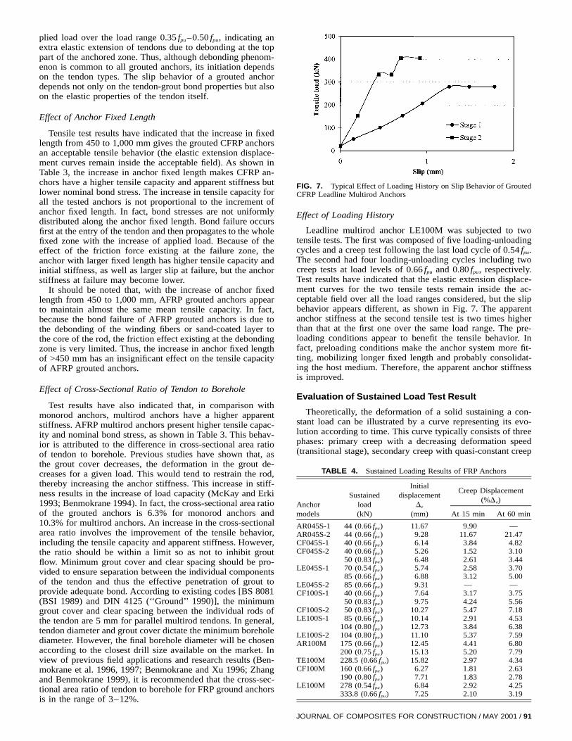
FIG. 7. Typical Effect of Loading History on Slip Behavior of GroutedCFRP Leadline Multirod Anchors
TABLE 4. Sustained Loading Results of FRP Anchors
Anchormodels
Sustainedload(kN)
Initialdisplacement
De
(mm)
Creep Displacement(%De)
At 15 min At 60 min
AR045S-1 44 (0.66 fpu) 11.67 9.90 —AR045S-2 44 (0.66 fpu) 9.28 11.67 21.47CF045S-1 40 (0.66 fpu) 6.14 3.84 4.82CF045S-2 40 (0.66 fpu) 5.26 1.52 3.10
50 (0.83 fpu) 6.48 2.61 3.44LE045S-1 70 (0.54 fpu) 5.74 2.58 3.70
85 (0.66 fpu) 6.88 3.12 5.00LE045S-2 85 (0.66 fpu) 9.31 — —CF100S-1 40 (0.66 fpu) 7.64 3.17 3.75
50 (0.83 fpu) 9.75 4.24 5.56CF100S-2 50 (0.83 fpu) 10.27 5.47 7.18LE100S-1 85 (0.66 fpu) 10.14 2.91 4.53
104 (0.80 fpu) 12.73 3.84 6.38LE100S-2 104 (0.80 fpu) 11.10 5.37 7.59AR100M 175 (0.66 fpu) 12.45 4.41 6.80
200 (0.75 fpu) 15.13 5.20 7.79TE100M 228.5 (0.66 fpu) 15.82 2.97 4.34CF100M 160 (0.66 fpu) 6.27 1.81 2.63
190 (0.80 fpu) 7.71 1.83 2.78LE100M 278 (0.54 fpu) 6.84 2.92 4.25
333.8 (0.66 fpu) 7.25 2.10 3.19
Effect of Loading History
Leadline multirod anchor LE100M was subjected to twotensile tests. The first was composed of five loading-unloadingcycles and a creep test following the last load cycle of 0.54 fpu.The second had four loading-unloading cycles including twocreep tests at load levels of 0.66 fpu and 0.80 fpu, respectively.Test results have indicated that the elastic extension displace-ment curves for the two tensile tests remain inside the ac-ceptable field over all the load ranges considered, but the slipbehavior appears different, as shown in Fig. 7. The apparentanchor stiffness at the second tensile test is two times higherthan that at the first one over the same load range. The pre-loading conditions appear to benefit the tensile behavior. Infact, preloading conditions make the anchor system more fit-ting, mobilizing longer fixed length and probably consolidat-ing the host medium. Therefore, the apparent anchor stiffnessis improved.
Evaluation of Sustained Load Test Result
Theoretically, the deformation of a solid sustaining a con-stant load can be illustrated by a curve representing its evo-lution according to time. This curve typically consists of threephases: primary creep with a decreasing deformation speed(transitional stage), secondary creep with quasi-constant creep
JOURNAL OF COMPOSITES FOR CONSTRUCTION / MAY 2001 / 91

FIG. 8. Creep Displacement of Grouted FRP Anchors under SustainedLoad Conditions: (a) Monorod Tendon; (b) Multirod Tendon
TABLE 5. Creep Displacement of Prestressed FRP Anchor Tendons
Anchormodels
Sustainedload(kN)
Initial strainε i
(1023)
Creep Displacement(%ε i)
At 15 min At 60 min
AR100M 175 (0.66 fpu) 15.74 2.00 2.92200 (0.75 fpu) 17.98 2.09 3.12
LE100M 278 (0.54 fpu) 8.75 0.41 0.65333.8 (0.66 fpu) 10.51 0.86 1.13
speed (stationary state property), and tertiary creep with anincreasing creep until rupture. With regard to the sustainedload tests of prestressed grouted anchors, the acceptance cri-teria differ from one country to another according to the stan-dards and recommendations in effect. The BSI requires a limitof 5% of the initial displacement of the grouted anchors after15 min of test; other codes stipulate a limited creep displace-ment of about 2 mm for prestressed permanent steel anchorsinjected in a host medium not presenting a significant creep[BS 8081 (BSI 1989); Habib 1989; DIN 4125 (‘‘Ground’’1990); Post-Tensioning Institute (PTI) 1990]. The BSI thusmakes it possible to take into account the elastic properties ofthe tendons and seems to be more restrictive. Therefore, theobtained results will be compared exclusively with the accep-tance criterion of the BSI.
Sustained load test results indicated that, except for anchorsAR045S-1 and LE045S-2, which showed creep failure at thetendon-grout interface, all other anchors presented the first twostages of creep curve for 60 min of sustaining load tests. Thecreep displacement of grouted FRP anchors is influenced bytendon type and constituent, fixed length, load level, and load-ing history. As shown in Table 4, AFRP grouted anchors pre-
sspatacii5ldusl
m0aclptTaCtci
C
afalarctoFi
92 / JOURNAL OF COMPOSITES FOR CONSTRUCTION / MAY 2001
ent a higher creep displacement than CFRP ones under theame conditions. Monorod anchors show a higher creep dis-lacement than multirod ones. The increase in cross-sectionalrea ratio of tendon to borehole appears to improve the sus-ained loading behavior. A longer anchor fixed length involves
reduction in creep displacement, especially in the primaryreep speed. The increase of the sustained load gives rise toncrease in the creep displacement. Furthermore, the tendontself creeps under sustained constant load. As shown in Table, the readings from the strain gauges installed over the freeength of AFRP grouted anchor AR100M indicate that the ten-on creep deformations after 60 min are 0.046 and 0.056%nder loads of 0.66 fpu and 0.75 fpu, respectively. These resultseem to agree with the creep deformation of 0.04% under aoad of 0.50 fpu obtained by Gerritse (1993).
Fig. 8 shows the creep displacements of the monorod andultirod anchors after 15 min. Subjected to a constant load of
.66 fpu, all the tested CFRP (CFCC and Leadline) monorodnchors and FRP multirod anchors demonstrate an acceptablereep behavior, whereas AFRP Arapree anchors with a fixedength of 450 mm show a higher creep displacement, in com-arison with BS 8081 (BSI 1989). Under a load of 0.80 fpu,he tested FRP grouted anchors show variable creep behavior.he behaviors of anchors CF045S-2, CF100S-1, LE100S-1,nd CF100M are acceptable, whereas anchors AR100M,F100S-2, and LE100S-2 show a higher creep displacement
han the BSI limit. In comparison with the tensile test results,reep behavior appears to control the long-term tensile capac-ty of grouted FRP anchors.
ONCLUSIONS
In this investigation, laboratory uplift tests on 16 monorodnd 4 multirod (4-rod) FRP grouted anchors were conductedollowing the standard test procedures. Four types of AFRPnd CFRP anchor tendons and two types of anchor fixedengths were investigated. Experimental results on the evalu-tion of tensile behavior of cement-grouted FRP anchors wereeported. The effects of parameters, such as tendon type andonstituent, anchor fixed length, cross-sectional ratio of tendono borehole, and loading history, were discussed. The resultsbtained would assist practicing engineers in the design ofRP anchors for applications in civil engineering. In particular,
t was found that
• The stress-strain relation of FRP rods is linear at all stresslevels up to the point of failure, without exhibiting anyyielding of the material. The manufacturers’ values ofstrength, modulus of elasticity, and ultimate strain appearto be in good agreement with experimentally derived re-sults. Compared with the reported mean ultimate capacity,the tested mean value is 5% lower for Arapree rods, about10% higher for Leadline rods, and 5% higher for CFCC.
• FRP multirod ground anchors show an acceptable tensilebehavior with higher tensile capacity. The maximum ac-ceptable proof load varies with tendon type, 0.60 fpu forArapree, 0.66 fpu for Technora, and 0.83 fpu for CFRPCFCC and Leadline.
• Subjected to a proof load of 0.66 fpu, all tested FRPmultirod grouted anchors show an acceptable creep be-havior according to existing codes. However, creep be-havior controls the long-term load-bearing capacity ofprestressed FRP ground anchors. The creep behavior ofgrouted FRP anchors should be evaluated in practical an-chor conditions including tendon components, injectedgrout, host medium, and service conditions. This aspectwill be investigated in future studies.
• It is recommended to use FRP multirod ground anchorsin engineering practice. The design working load is

0.40 fpu for AFRP and 0.50 fpu for CFRP. The cross-sec-tional area ratio of tendon to borehole should be 3–12%,provided that the minimum grout cover and clear spacingbetween the individual rods of the tendon are 5 mm forparallel multirod tendons.
ACKNOWLEDGMENTS
The Natural Science and Engineering Research Council of Canada,(Ottawa), the Canadian Network of Centres of Excellence on IntelligentSensing for Innovative Structures [(ISIS-Canada), Winnipeg, Manitoba],Dywidag DSI Inc. (Toronto, Ontario), Montaki Inc. (Montreal, Quebec),Mitsubishi Kasei Corp. (Tokyo, Japan), Sireg SpA (Arcore, Italy), TeijinInc. (New York, United States), and Tokyo Rope Mgf. Co., Ltd. (Tokyo,Japan) are gratefully acknowledged for their support.
REFERENCES
Aoyagi, K., Yoshida, T., Yamazai, Y., and Maruyama, K. (1996). ‘‘NM(new material) ground anchor system.’’ Proc., 2nd Int. Conf. on Ad-vanced Compos. Mat. in Bridges and Struct., Canadian Society forCivil Engineering, Montreal, 727–734.
Benmokrane, B. (1994). ‘‘Grouted anchorages for aramid fibre reinforcedplastic prestressing tendons: Discussion.’’ Can. J. Civ. Engrg., Ottawa,21, 713–715.
Benmokrane, B., Chennouf, A., and Mitri, S. (1995). ‘‘Laboratory eval-uation of cement-based grouts and grouted rock anchors.’’ Int. J. RockMech. Mining Sci. and Geomechanics Abstracts, 32(7), 633–642.
Benmokrane, B., Xu, H., and Bellavance, E. (1996). ‘‘Bond strength ofcement ground glass fibre reinforced plastic (GFRP) anchor bolts.’’ Int.J. Rock Mech. Mining Sci. and Geomechanics Abstracts, 33(5), 455–465.
Benmokrane, B., Xu, H., and Nishizaki, I. (1997). ‘‘Aramid and carbonfibre-reinforced plastic (FRP) prestressed ground anchors and their fieldapplications.’’ Can. J. Civ. Engrg., Ottawa, 24(6), 968–985.
Benmokrane, B., Zhang, B., and Chennouf, A. (1999). ‘‘Tensile propertiesand pullout behaviour of AFRP and CFRP rods for grouted anchorapplications.’’ Constr. and Build. Mat., 14(3), 157–170.
British Standards Institution (BSI). (1989). ‘‘British standard of practicefor grouted anchorages.’’ BS 8081, London, 74–87.
Canadian Society for Civil Engineering (CSCE). (1998). ‘‘Fiber rein-forced structures (Section 16).’’ Canadian highway bridge design code,Montreal, 28.
El-Badry, M. M. (1996). ‘‘Advanced composite materials in bridges andstructures.’’ Proc., 2nd Int. Conf. on Advanced Compos. Mat. in Bridgesand Struct., Canadian Society for Civil Engineering, Montreal, 722.
Gerritse, A. (1993). ‘‘Aramid-based prestressing tendons.’’ AlternativeMaterials for the reinforcement and prestressing of concrete, J. L.Clarke, ed., Blackie Academic and Professional, London, 172–201.
‘‘Ground anchorages: Design, construction and testing.’’ (1990). DIN4125, Beuth Verlag Gmbh, Berlin.
Habib, P. (1989). Recommendations for the design, calculation, construc-tion and monitoring of ground anchors, Balkema, Rotterdam, TheNetherlands.
Hassani, E. P., and Khan, U. H. (1993). ‘‘Arapree: A cuttable cable-boltsupport system.’’ Innovative mine design for the 21st century, W. F.Bawden and G. Archibald, eds., Balkema, Rotterdam, The Netherlands,119–130.
Khan, U. H., and Hassani, H. P. (1993). ‘‘Analysis of new flexible andrigid composite tendons for mining.’’ Innovative mine design for the21st century, W. F. Bawden and G. Archibald, eds., Balkema, Rotter-dam, The Netherlands, 1033–1043.
McKay, K. S., and Erki, M. A. (1993). ‘‘Grouted anchorages for aramidfibre reinforced plastic prestressing tendons.’’ Can. J. Civ. Engrg., Ot-tawa, 20, 1065–1069.
Mitsubishi Kasei Corp. (1992). ‘‘Leadline carbon fibre rods: Technicaldata.’’ Technical Rep., Tokyo.
Mochida, S., and Hoshijima, T. (1996). ‘‘Evaluation of anchorage capac-ity for ground anchor using high strength carbon materials.’’ Proc.,
2nd Int. Conf. on Advanced Compos. Mat. in Bridges and Struct., Ca-nadian Society for Civil Engineering, Montreal, 943–950.
Mochida, S., Tanaka, T., and Yagi, K. (1992). ‘‘The development andapplication of a ground anchor using new materials.’’ Proc., 1st Int.Conf. on Advanced Compos. Mat. in Bridges and Struct., K. W. Nealeand P. Labossiere, eds., Canadian Society for Civil Engineering, Mon-treal, 393–402.
Nanni, A., and Dolan, C. W., eds. (1993). ‘‘Fibre reinforced plastic re-inforcement for concrete structures.’’ Proc., Int. Symp., ACI SP-138,American Concrete Institute, Detroit, 977.
Neale, K. W., and Labossiere, P., eds. (1992). ‘‘Advanced composite ma-terials in bridges and structures.’’ Proc., 1st Int. Conf. on AdvancedCompos. Mat. in Bridges and Struct., Canadian Society for Civil En-gineering, Montreal, 705.
Noisternig, J. F., and Jungwirth, D. (1996). ‘‘Design and analysis of an-choring system for a carbon fiber composite cable.’’ Proc., 2nd Int.Conf. on Advanced Compos. Mat. in Bridges and Struct., M. M. El-Badry, ed., Canadian Society for Civil Engineering, Montreal, 935–942.
‘‘Non-metallic (FRP) reinforcement for concrete structures.’’ (1997).Proc., 3rd Int. RILEM Symp. (FRPRCS-3), Japan Concrete Institute,Sapporo, Japan, 1:728 and 2:813.
Noritake, K., Kakihara, R., Kumagai, S., and Mizutani, J. (1993). ‘‘Tech-nora, an aramid FRP rod.’’ Fibre-reinforced-plastic (FRP) reinforce-ment for concrete structures: Properties and applications, A. Nanni,ed., Elsevier Science, New York, 267–290.
Recommendations for prestressed rock and soil anchors. (1990). Post-tensioning Institute (PTI), Phoenix.
Saadatmanesh, H., and Ehsani, M. R., eds. (1996). ‘‘Fibre composite ininfrastructure.’’ Proc., 1st Int. Conf. on Compos. in Infrastructure, Uni-versity of Arizona, Tucson, Ariz., 1231
Saadatmanesh, H., and Ehsani, M. R., eds. (1998). ‘‘Fibre composite ininfrastructure.’’ Proc., 2nd Int. Conf. on Compos. in Infrastructure,University of Arizona, Tucson, Ariz., 1:723 and 2:783.
Taerwe, L., ed. (1995). ‘‘Non-metallic (FRP) reinforcement for concretestructures.’’ Proc., 2nd Int. RILEM Symp. (FRPRCS-2), University ofGhent, Ghent, Belgium, 714.
‘‘Technical data on CFCC.’’ (1993). Tokyo Rope Co. Ltd., TokyoZhang, B., and Benmokrane, B. (1999). ‘‘Experimental and theoretical
investigation on FRP bond anchorage and grouted anchors.’’ Tech. Rep.Submitted to Dept. of Civ. Engrg., University of Sherbrooke, Sher-brooke, Que., Canada.
Zhang, B., Benmokrane, B., and Chennouf, A. (2000). ‘‘Prediction oftensile capacity of bond anchorages for FRP tendons.’’ J. Compos. forConstr., ASCE, 4(2), 39–47.
NOTATION
The following symbols are used in this paper:
At = cross-sectional area of tendon;Et = elastic modulus of tendon unit from manufacturer;fpu = characteristic strength or guaranteed ultimate tensile
strength or load;Kapp = anchor apparent stiffness;Lapp = anchor apparent free length;
Ld = designed anchor free length;S = distance of LVDT from top of bonded length;T = peak cycle load minus datum load;Ti = initial seating load (datum load);
Tmax = maximum applied load;Tw = design working load;De = elastic displacement of tendon;d = total slip of tendon inside grout;
dbar = tendon elastic elongation;dmea = measured total displacement;
ε i = axial tension strain of tendon; andtmax = maximum bond stress.
JOURNAL OF COMPOSITES FOR CONSTRUCTION / MAY 2001 / 93