tensile and low-cycle compressive tests on a natural ...€¦ · tensile and low-cycle compressive...
TRANSCRIPT
Tensile and low-cycle compressive tests on a natural structural stone
M.L. Beconcini, S. Bennati & W. Salvatore Department of Structural Engineering, University of Pisa, Italy
Abstract
The present work presents some first results of an experimental study in which samples of a natural-occurring stone, called "leccese", were subjected to fatigue through low- cycle tests in the presence of h g h compressive stresses. The specimens' behatiour remains o ~ i c a l up to the last cycle, during whch brittle failure occurs. with gradual accumulation of permanent strains. Other tests by pure tension or compression performed up to failure on samples previously subjected to a interrupted low-cycle fatigue test, confirmed that during such fatigue cycles the damage process is accompanied by meaningful variations in some significant mechanical parameters, amongst which, the Young elastic modulus and tensile strength are particularly telling.
1. Introduction
Leccese stone is a sedimentary rock dating back to the Miocene epoch [l], whose easy workability and, in some cases, good mechanical characteristics made it the material of choice in the construction of Baroque churches throughout a wide geographic area in the south of Italy. Particularly, Leccese Baroque architecture, known for its origmality and figurative richness, was developed in Italy's southern Salento region in the atmosphere of restoration following the 1647 upheavals. It developed within the framework of the rivalry between two religious orders: the Jesuits, supported by local aristocrats, and the Celestini monks. Thus in Lecce, the city whence the name "Leccese" derives, even before construction of the cathedral (fig. l), the Chiesa del Gesu, a clear expression of Counter Reformation dogma (fig. 2), was contrasted by the architecture of the Monastery and, above all, the magnificent Church of Santa Croce (fig. 3 and 4), perhaps the most renowned construction from that period [2]. The soft and workable Leccese stone is a beautiful warm yellow-coloured calcareous sedimentary stone, composed of over 50% calcite. the remainder being glauconite and
Transactions on the Built Environment vol 55, © 2001 WIT Press, www.witpress.com, ISSN 1743-3509

484 Shchrral Studies, Repairs and Maintenance of Historzcai Buildings
apatite, minerals typical of sedimentary rock of marine origins and those produced by the accumulation of organic remains, respectively. On microscopic examination (figure 6), Leccese presents as a detritic carbonate sediment, for the most part fine-grained, sometimes friable, other times compact [l], [3], [4].
Jesus - the pelican is a symbol of the It~cnrnation and ChastiQ)
~ k s e ~ ~ e Zimbalo)
Figure 3. Celestini palace (Lecce) ~ i @ e 4. Church of Santa Croce (Lecce)
Figures 5. Church of Santa Croce (Lecce): detail of the second tier
Figure 6. Electron microscope (SEM) image of a Leccese stone sample
Transactions on the Built Environment vol 55, © 2001 WIT Press, www.witpress.com, ISSN 1743-3509
Apart from being easily worked, Leccese is also quite homogeneous, and thus ideal for experimental study of the mechanisms involved in the decay of natural building stones. In effect, the tests performed during the first part of this research, obtained from blocks excavated from a quarry in Cursi (Lecce), evidenced the uniformity of the rock's behaviour stemming from its structural homogeneity. Such homogeneity. in fact. translates into the umform results obtained in the simple compression, direct tensile and low-cycle fatigue tests. The second stage of experimental research focused instead on the possibility of producing and measuring increasing levels of damage of the material making up the specimens by using carefully planned low-cycle fatigue tests. Degradation of the mechanical characteristics of building stone is nearly always accompanied by the progressive decohesion of its constituent grains [5], [6], [7]. Understandably, such decohesion is revealed by a marked reduction in the stone's strength. The studies present in the literature, however, refer to indirect tensile tests by bending or compression, which are actually quite difficult to interpret [8]. For this reason, pure tensile tests were performed on samples which had already undergone a certain degree of damage during low-cycle compression fatigue tests. interrupted before failure was reached. The earliest results, presented in the current work, suggest that a meaningful relationship may exist between the values of residual tensile strength and the Young elastic modulus, on the one hand, and the number of cycles and tensile range of the fatigue test, on the other.
2. Experimental tests: materials and methods
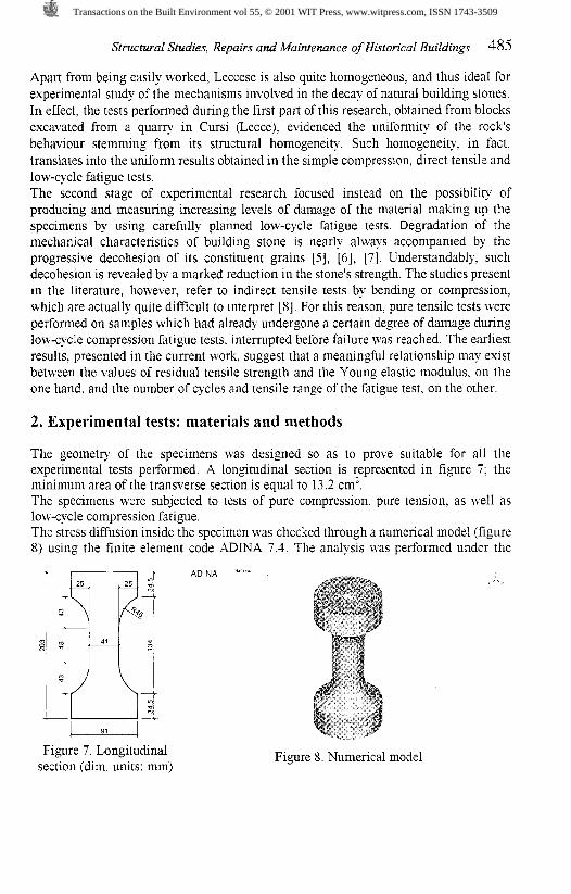
The geometry of the specimens was designed so as to prove suitable for all the experimental tests performed. A longitudinal section is :epresented in figure 7; the minimum area of the transverse section is equal to 13.2 cm'. The specimens were subjected to tests of pure compression, pure tension, as well as low-cycle compression fatigue. The stress diffusion inside the specimen was checked through a numerical model (figure 8) using the finite element code ADWA 7.1. The analysis was performed under the
Figure 7. Longitudinal section (dim. units: mm)
Figure 8. Numerical model
Transactions on the Built Environment vol 55, © 2001 WIT Press, www.witpress.com, ISSN 1743-3509

486 Structural Studies, Repairs and Maintenance ofHistorica1 Buildings
hypothesis that the friction between the test apparatus and the specimen was high enough to prevent deformation of the base of the specimen in its plane, while the load was applied by imposing a uniform displacement in correspondence to the upper base until a tensile stress was produced in the reduced section equal to 1.5 ~ l m m ~ , close to the expected ultimate tensile strength. The material's behaviour was assumed to be linear elastic with modulus equal to 7000 ~ / m m ' and Poison's ratio v equal to 0.15. The results of the analysis confirmed a satisfying uniformity of the stresses within the reduced sections of specimen (figure 9). Figure 10 presents the pattern of normal stress G, for four different transverse sections. In particular, in correspondence to the middle section D-D, the mean value and standard deviation of the normal stresses o, result to be equal to 1.5 and 0.007 ~ lmm' , respectively. Particular care was exerted in planning the testing apparatus. In the case of the tensile tests (figure l l ) , the specimens' bases, perforated at the centres. were treated with
Figure 9. Normal stresses o, (transversal section along the y-z plane).
Figure 10. Pattern of normal stresses o, within the sample
Transactions on the Built Environment vol 55, © 2001 WIT Press, www.witpress.com, ISSN 1743-3509

cyano-acrylate and glued to two steel plates, also perforated, with a special two- component HBM glue. Centring was guaranteed by means of a bolt with torus-shaped head on whch a steel chain was hooked to transfer the load (figure 11). In the compressive test the coincidence of the load axis with the specimen axis was guaranteed by means of two mechanical joints, the lower of which is an integral part of the test apparatus, and two steel plates expressly perforated or moulded (figure 12). The low-cyclic compressive tests were performed using the same device.
Test machne Test machine
Pm p n t
Steel plate
Matchlng hale
Steel plate
Stone speamen Stone specmen
Cyaro-acrylale resm and blcornponent glue HBM Schnellklebstoff 1-X60
Steel plate for specmen matching
Matchlrq hole
Pin joln!
Steel plate
&- Test machme
Test rnachme
Figure 1 1. Tensile test apparatus. Figure 12. Monotonic and cyclic compressive test apparatus.
The tests were carried out using a Instron Model 1186 (figures 13 and 14) for control of the displacement. After several attempts, the feed velocity for all the tests was set at 0.2 mrnhin. The specimens were fitted with two strain gauges (L = 10 mm) and two rectangular rosettes (3 x L = 10 mm) applied at about half height (figure 15) in diametrically opposite positions. The rosettes were positioned such that the direction of a strain gauge were approximately parallel to that of application of the load. The strain gauges and rosettes were glued with two-component HBM glue on the surface treated with cyano-acrylate. Control of the test apparatus (displacement control) and data acquisition and recording (instantaneous load and extension of the strain gauges) were effected by means of sofhvare expressly developed by the authors. The vertical, oblique and horizontal strains, measured by the rosettes allowed determining the principal axial and tangential strains, E, and G, respectively, as well as the principal directions. In accordance with the hypothesis of homothetic expansion or contraction of the transverse section the principal strain in the radial direction, G, was assumed to be equal to the tangential one.
Transactions on the Built Environment vol 55, © 2001 WIT Press, www.witpress.com, ISSN 1743-3509

488 Structural Studies, Repairs and Maintenance of Historical Buildings
Figure 13. Tensile test. Figure 14. Compressive Figure 15 test. Equipped specimen.
3. Experimental results
In a first experimental stage, pure tensile and compressive tests were performed up to failure in order to determine the values of the elastic modulus and the tensile and compressive strengths of the stone. Figures 16 and 17 show the behaviour of the principal strains, and of the deviatoric ones, as function of the principal vertical stress o, for a typical pure compressive test; analogously figures 18 and 19 show the behaviour of the same quantities for a typical pure tensile test. Table 1, in turn, reports the mean values and the standard deviations of the ultimate stresses, o,, and o,, , the maximum strains, E, ,, and E, ut, as well as the mean, E,, and E, ,, and tangent, E,, and E, ,, elastic moduli, calculated according to the Italian standard, UN1 93741811992, and relative to the six successfully performed compressive tests and to the five pure tensile tests.
3000 2000 1000 0 -1000 -2000 -3000 d W 0
Stain [jlEl
Figure 16. Compressive test: principal strains vs. principal vertical stress
Transactions on the Built Environment vol 55, © 2001 WIT Press, www.witpress.com, ISSN 1743-3509

Stmehtml Studies, Repairs and Maintenance ofHistancal Buildings 489
; -180 5 5 -160 P '3
4 4 0 L
Zi -r20
-100
8 0
4 0
d o
-20
0 3000 2000 1000 0 -'000 -2000 -3000 4 0 0 0
Strain [url
Figure 17. Compressive test: spherical strain, &I, and deviatoric strain, and E~ VS, principal vertical stress
-100 -50 0 50 $ 0 0 '50 200 250 300 350
Strain [PE]
Figure 18. Tensile test: principal strain vs. principal vertical stress. ,- 20 E 2 3 6
2. '3 16
14
12
10
B
6
4
2
0 -1C0 -50 0 50 100 150 230 250 300 353
Strain [W]
Figure 19. Tensile test: spherical strain, &I, and deviatoric strains, ~d and ~d 2 , VS. principal vertical stress.
Transactions on the Built Environment vol 55, © 2001 WIT Press, www.witpress.com, ISSN 1743-3509

490 Stntcturd Studies, Repairs and Maintenance of Historical Buildings
Standard 1 Deviation 1 84.9 ; 6317.2 1 7116.1
Tensile tests
Tangent Elastic Modulus
E,, [daN/cm2]
60364.0
Conzpression tests
Mean value
Mean value
Standard Deviation
Ultimate Stress
o, , [daN1cm2]
-162.0
Ultimate Stress Ultimate Strain Mean Elastic Tangent Elastic G , , d a 1 c m 2 1 E , [PE] Modulus MOdulus 1
E,, [daN/cm2] Et, [daNicm2]
Table 1. Compression and tensile test results
Ultimate Strain
E, ,, [PE]
Subsequently, low-cycle compressive tests were performed, during which the specimens were brought to failure after a number of cycles varying from 3 to 46. Figure 20 shows the values of the principal strains, E, and E+, as a function of the principal vertical stress G, during one of the low-cycle compressive tests. The results of the cyclic tests performed are summarized in Table 2. Figure 20 clearly shows a regular growth of permanent vertical and tangential strains, which suggests a gradual damage process under way in the material of the specimen. With the aim of verifying whether this hypothesis was well-founded, in the last stage of the study, the specimens were first subjected to low-cycle compressive tests that were interrupted before specimen's failure; they were thereafter brought to failure through either a pure tensile or compressive test.
Mean Elastic Modulus
E,, [daNicm2]
- -160 E * 5 . l40 e V)
W -1 W
-80
-60
4 0
-20
0
3000 2000 1000 0 .1000 .ZOO0 -3COO
Strain W E ]
-3224.3 1 71107.5
Figures 20: Low-Cycle compressive test up to failure: principal strains vs. principal vertical stress.
Transactions on the Built Environment vol 55, © 2001 WIT Press, www.witpress.com, ISSN 1743-3509

Table 2. Low-cycle compressive test results
Figure 21 represents the principal strains, E, and G, as a function of the principal vertical stress, 0,: during one of the interrupted low-cycle compressive tests. Figures 22 and 23, instead, show the principal strains (once again with varying principal vertical stress), E, and G, and the spherical, E,, and deviatoric, and &d 2, components relative to the subsequent monotonic test performed on the damaged specimen.
- -1 50
1 2 -140 P. m
P - lZ0 G
-100
-80
-60
.40
.20
0
3000 2000 1000 0 -1000 4 0 0 0 -3000
Strain IJE]
Test N.
0 1 02
E h u [PE]
2917 1714
Figure 2 1. Interrupted low-cycle compressive test: principal strains vs. principal vertical stress.
A 0 [ d a ~ l c m ' ~
-127 0
-128 0
Urn [daNlcm2]
-80.5 -86 0
cycles 1
13 16
3000 2000 1000 0 -1000 -2000 -3000 4 0 0 0
Strain [W]
EY U [PE]
-3784 -2826
Figure 22. Compressive test on damaged specimen: principal strains vs. principal vertical stress.
Transactions on the Built Environment vol 55, © 2001 WIT Press, www.witpress.com, ISSN 1743-3509

492 Structural Studies, Repairs and Maintenance of Historical Buildings
spherical
W- .?@l
4 5 -<€a -0
B .>a 2
-120
- r m
4 0
6 0
d o
-20
0
3000 m 0 l 0 m 0 .?WO -2OW -3000 4000
Strain Luel
Figure 23. Compressive test on damaged specimen: strain EI and deviatoric stresses, and ~d.2, VS. principal vertical stress.
Table 3 shows the results related to the two successfully performed compressive tests up to failure camed out on the fatigue-damaged specimens.
Test
Table 3. Damage analysis by compressive tests
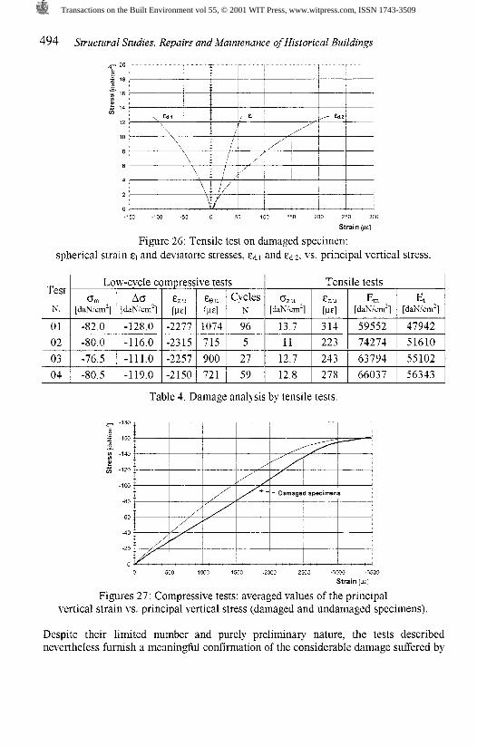
Analogously, figure 24 represents the principal strains, E, and Ee, dunng one of the interrupted low-cycle compressive tests, as a hnction of varying principal vertical stress, G,, while figures 25 and 26 show the principal strains, E, and EO and spherical, E,,
and deviatoric, and components of the tensor of strain, relative to the subsequent monotonic test performed on the damaged specimen. Table 4 summaries the results of the four successful tensile tests performed on fatigue- damaged specimens.
Low-cycle compressive tests
4 Some remarks
Compressive tests
0, [da~/cm~]
-74.0
-79.0
Figures 27 and 28 show the averaged response (expressed by the behaviour of tlle principal vertical stress as a function of the longitudinal strain, E,) of the intact and fatigue-damaged specimens for pure compressive and tensile tests, respectively. By examining figure 27, it can clearly be seen that any damage to the material consequent to the low-cycle fatigue tests modifies the ultimate strain only slightly, while it does not seem to affect the compressive strength at all. The most meaningful aspect, however, is related to the varying behaviour of the tangent elastic modulus, whch remains practically constant during the entire compressive test in the case of the
ozu [dapJ/cm2]
-154
-169
A [&~/cm']
-104.0 -116.0
E,, [PE]
p--
-3650
-3292
cZu [ p ]
-2879
-2671
L, [da~/cm']
17415
57813
Et [daS/cm2]
47505
59655
G, [PE]
1324
1020
Cycles pJ
54
103
Transactions on the Built Environment vol 55, © 2001 WIT Press, www.witpress.com, ISSN 1743-3509

damaged specimens; while, on the other hand, in the case of the intact, "undamaged" specimens, it varies considerably with increasing load. Overall, however, the damaged specimen, despite having been subjected to severely fatiguing load cycles, exhibits behaviour that is barely distin,~shable from that of the intact specimen. On the contrary, as figure 28 shows, during the pure tensile tests, the intact specimens can easily be distinguished from the damaged ones. The latter, in fact, exlubit a decidedly non-linear load curve; their ultimate strain is considerably higher and the elastic modulus has undergone a conspicuous decrease; finally, the tensile strength is reduced to a significant degree. It appears reasonable to attribute such changes in behaviour under a tensile stress to a damage process, during which phenomena of decohesion of the aggregate and more or less wide micro-cracking ensue. It is also easy to understand how such phenomena do not sigmfkantly mod@ the behaviour of the specimen under compressive stresses.
3 W O 2000 1000 0 -1 W 0 .ZOO0 4000
Strain be]
Figure 24. Interrupted low-cycle compressive test: principal strains vs. principal vertical stress.
-100 .M 0 50 100 3 % 230 250 3W 350
Strain W]
Figure 25. Tensile test on damaged specimen: principal strains vs. principal vertical stress.
Transactions on the Built Environment vol 55, © 2001 WIT Press, www.witpress.com, ISSN 1743-3509
494 Structrral Studies, Repairs and Maintenance of Historical Buildings
-150 1 -50 0 50 100 150 200 250 300
Strain ~ E I
Figure 26: Tensile test on damaged specimen: spherical strain EI and deviatoric stresses, E* and E* 2 , VS. principal vertical stress.
Table 4. Damage analysis by tensile tests
- 1 m T l
i Damaged specimens -80 1 /
/ / l
Test
N.
0 -500 -lWO -1500 .2000 -2500 -3WO -3505
Strain [W]
Figures 27: Compressive tests: averaged values of the principal vertical strain vs. principal vertical stress (damaged and undamaged specimens).
Tensile tests
Despite their limited number and purely preliminaq nature, the tests described nevertheless furnish a meaningful conlirmation of the considerable damage suffered by
0," [daK/cm2]
Low-cycle compressive tests
%I
[ d a ~ i c r n ~ ] & U
[we] 0
[da~krn ' ] [daK/cm2] Ef
[daX cmZ] EZU [ p ]
Eeu [PE]
Cycles N
Transactions on the Built Environment vol 55, © 2001 WIT Press, www.witpress.com, ISSN 1743-3509

the stone material during the low-cycle compressive test. During the test itself, such damage is only hlnted at by the increase in permanent axial and tangential strains. It is intention of the authors to continue this line of experimental research, whose first results are presented here, with the main aim of determining possible meaningful relationships behveen the intensity and number of cycles, on the one hand, and any potential indicator of the actual damage experienced, on the other. If further tests confirmed this possibility, it will likely probably be possible to use low-cycle compressive tests, either alone, or preferably in combination with others types of artificial aging (such as those based on temperature cycles or exposure in climatic cells to aggressive atmospheres) to evaluate the durability of dfferent varieties of the same stone or samples drawn from structural elements of historical buildings subjected to decay.
18
j 16 0 $ 14
e G 12
1 0
8
6
4
2
0 0 50 103 150 200 250 300
Strain [W]
Figures 28: Tensile tests: averaged values of the principal vertical strain vs. principal vertical stress (damaged and undamaged specimens)
Acknowledgments
The authors would like to express their gratitude to the technicians Franco Pratelli and Simone Cavallini for their collaboration and aid in preparing and carrying out the experimental tests, to Eleonora Procopio, who kindly supplied the photos of the monuments in Lecce.
References
[ l ] Bossio, A., Guelfi, F., Mazzei, R., Monteforti. B., Salvatorini, S. Note geologivhe e stratigrafiche sull'area di Palmariggi (Lecce, Puglia). Rivista Iraliat~a Paleonr. Strat., 97, 2, pp. 175-234, 1991 (in Italian).
[2] Manieri Elia M. Documenti di drchitettura. Barocco Leccese. Electa ed., Milano. 1996 (in Italian).
[3] Bossio, A., Mazzei, R., Monteforti, B., Salvatorini, S. Studi sul neogoene e quaternario della penisola salentina 11. Evoluzione p a l e o g e ~ g r ~ c a dell'area di
Transactions on the Built Environment vol 55, © 2001 WIT Press, www.witpress.com, ISSN 1743-3509
496 Structural Studies, Repairs and Maintenance of Historical Buildings
Leuca nel contest0 della dinamica mediterranea. Quad Ric. Cenrro Studi Geot. E d %g., 11 , pp. 31-54, 1994 (in Italian)
[4] Mazzei, R. Eta della pietra leccese nell'area di Cursi-Melpignano (a sud di Lecce, Puglia). Bollettino della Societa Paleontologica Italians, 33(2), pp. 293-298, 1994 (in Italian).
[5] Hardy, Jr H.R., Chug, Y.P. Failure of geological materials under low-cycle fatigue. Proceedings of the Sixth Canadian Symposium on Rock Mechanics, Montreal, Canada, May 1970.
[6] Royer-Carfagni, G., Salvatore, W. Localised fatigue damage of carrara marble. Damage and Fracture Mechanics. Carpinteri, A., Brebbia, C.A. eds, Computational Mechanics Publications, Southampton, 1998.
[7] Royer-Carfagni, G., Salvatore, W. The characterization of marble by cyclic compression loading: experimental results, Mechanics of cohesive-frictional materials, 5 , pp. 535-563, 2000.
[g] Marini, P. Deterniinazione quantitativa del degrado delle pietre da decorazione e nzessa a punto di prove di invecchiamento accelerato per la previsione deNa loro curabilita, Thesis in partial fulfillment of the PhD degree, Politecnico di Torino, 1994 (in Italian)
Transactions on the Built Environment vol 55, © 2001 WIT Press, www.witpress.com, ISSN 1743-3509