“tensegrity based poultry shed” -...
TRANSCRIPT
Mini Project Report on
“TENSEGRITY BASED POULTRY SHED”
Submitted by:
NIKHIL VYAS
(2006CE10275)
Under Supervision of:
DR. SURESH BHALLA
Department of Civil Engineering
Indian Institute of Technology, Delhi
April, 2009
i
CERTIFICATE “I do certify that this report explains the work carried out by me in the course CED310, Mini
Project, under the overall supervision of Dr. Suresh Bhalla. The contents of the report including
text, figures, tables etc. have not been reproduced from other sources such as books, journals,
reports, manuals, websites, etc. Wherever limited reproduction from another source had been
made the source had been duly acknowledged at that point and also listed in the References.”
Nikhil Vyas
Date: April 21st,2009

ii
CERTIFICATE “This is to certify that the report submitted by Mr. Nikhil Vyas describes the work carried out by
him in the courses CED310 Mini-Project, under my overall supervision.”
Dr. Suresh Bhalla
Assistant professor Department of Civil Engineering
Indian Institute of Technology Delhi Date: April 24th 2009

iii
ACKNOWLEDGEMENT I would like to express my sincere thanks & gratitude to Dr. Suresh Bhalla for his continuous and
unfailing support, guidance and help, which have been invaluable during the course of this
project. His knowledge, insight and constant motivation at each step of the project has been
instrumental in its completion
I would like to take this opportunity to thank the entire staff at Structures Laboratory and the
Civil Engineering Laboratory for their unflinching support in the completion of this project
I would also like to thank my friends Rajat Dhanda, D.Hari Hara Rohit, Rachit Jain, Brahmajot
Singh Raheja for their help during the course of this project.
Nikhil Vyas
iv
ABSTRACT Tensegrity is a developing and relatively new system which creates amazing, lightweight and
adaptable structures, giving the impression of a cluster of struts floating in the air. They are a
special class of light-weight space truss structures, where the tensile elements are made of cables.
They are easy to construct and are light in weight. Another main advantage is that they can be
folded. Thus they will prove useful in coming years when structures which are space efficient
will be required.
Bamboo is a non characterized and non validated material which is readily available in
rural areas in India and has great scope as a building material.
The combination of the concept of tensegrity and bamboo as a building material has a vast
potential to result in eco-friendly, economical, structurally optimal structures which are light-
weight, earthquake resistant, transportable and storable. Thus we can have shelters or even
permanent structures made at a fraction of existing costs and still be more eco-friendly.
The objective of this project was to fabricate a “TENSEGRITY BASED POULTRY SHED”
structure using bamboo struts and jute ropes and the basics in tensegrity. Main emphasis was on
light weight quick fabrication, ease in folding and dismountability. The individual elements were
separately tested in the lab, and found suitable to resist likely loads
The complete structure was displayed in Open House’2009.

v
TABLE OF CONTENTS PAGE
CERTIFICATE i & ii
ACKNOWLEDGEMENT iii
ABSTRACT iv
TABLE OF CONTENTS v
LIST OF FIGURES viii
CHAPTER-1: INTRODUCTION 1
1.1 Definition of Tensegrity and Tensegrity Structures 1
1.2 Principle of Tensegrity Structures 2
1.3 Properties of Tensegrity Structures 2
1.4 Advantages and Disadvantages of Tensegrity Structures 3
1.5 Applications of Tensegrity Structures 5
1.6 Bamboo as a building material: Need and Advantages 6
1.7 Units Fabricated 7

vi
CHAPTER 2: FABRICATION METHODOLOGY 9
2.1 Column Fabrication 9
2.1.1 Stage 1: Joint Fabrication For Column 9
2.1.1.1 Joints used at base 9
2.1.1.2 Joints used in the middle 10
2.1.1.3 Joints used for connecting to roof 11
2.1.2 Stage 2: Cable Fabrication 12
2.1.3 Stage 3: Final Column Fabrication 12
2.2 Roof Fabrication 13
2.2.1 Stage 1: Joint Fabrication For Roof 13
2.2.1.1 Joints used at top of roof 13
2.2.1.2 Joints used in the middle of the roof base 14
2.2.1.3 Joints used at centre of roof 14
2.2.1.3 Joints used for connecting to column 15
2.2.2 Stage 2: Cable Fabrication 15
2.2.3 Stage 3: Final Roof Fabrication 16
2.3 Joining of Columns with Roof to Complete Final Structure 17

vii
CHAPTER 3: PRELIMINARY ANALYSIS 18
3.1. Testing Of Cables and Struts 18
3.1.1. Testing of Bamboo Struts 18
3.1.2. Testing of jute ropes 18
3.2. Check For Adequacy Of Members 19
CHAPTER 4: COMPARISON WITH PREVIOUS WORK 20
4.1 Comparison with Previous Work 20
CHAPTER 5: CONCLUSIONS AND RECOMMENDATIONS 23
5.1. Conclusions 23
5.2. Recommendations 23
REFERENCES 25
viii
List of Figures Figure Page
Fig1.1. Needle Tower by Kenneth Snelson (1968) 1
Fig1.2. Top view of simplex column 7
Fig1.3. Half-cuboctahedron structure 8
Fig2.1 Joint used at base 9
Fig2.2 Epoxy and hardener 10
Fig2.3 Joint used in the middle 10
Fig2.4 Joint used for connecting to roof 11
Fig2.5 Simplex Unit 12
Fig2.6. Finished column 12
Fig2.7. Joints used at top of roof 13
Fig2.8. Joints used in the middle of the roof base 14
Fig2.9. Joints used at centre of roof 14
Fig2.10. Joints used for connecting to column 15
Fig2.11.Half Cuboctahedron Unit 16

ix
Figure Page
Fig2.12.Finished Roof 16
Fig2.13.Final Shed Structure 17
Fig3.1.UTM used for testing bamboo Struts 18
Fig3.2.Spring Balance used for testing jute rope 19
Fig4.1: Previously used Circular-plate joint Source: K. Vijay Kumar (2007) 20
Fig4.2: Previously used central roof joint Source: Goyal A(2008) 20
Fig4.3: Previously used joint in the middle of Roof base Source: Mittal A(2008) 21
Fig4.4: Previously used column base joint Source: Goyal A(2008) 21
Fig4.5.Newly Fabricated Central Roof joint 21
Fig4.6.Newly Fabricated joint used in the middle of the roof base 21
Fig4.7 Newly Fabricated Column base joint 21

1
CHAPTER 1
INTRODUCTION
1.1 DEFINITION OF TENSEGRITY AND TENSEGRITY STRUCTURES
"The word 'tensegrity' is new invention and contraction of the phrase 'tensional integrity.'
Tensegrity describes a structural-relationship principle in which structural shape is guaranteed by
the finitely closed, comprehensively continuous, tensional behaviours of the system and not by
the discontinuous and exclusively local compressional member behaviours. Tensegrity provides
to the structure ability to yield increasingly without ultimately breaking or coming asunder"
Fig 1.1. Needle Tower by Kenneth Snelson (1968)
Tensegrity structures are three-dimensional space structures built of struts and cables attached to
the ends of the struts. The struts can resist the compressive force; the cables resist the tensile
forces. Most-strut-cable configuration which one might conceive is not in equilibrium, and if
actually constructed will collapse to a different shape, only strut-cable configuration in a stable
equilibrium will be called tensegrity structures.
2
1.2 PRINCIPLE OF TENSEGRITY STRUCTURES
Tensegrity structures are structures based on the combination of a few simple but subtle and deep
design patterns:
loading members only in pure compression or pure tension, meaning the structure will
only fail if the cables yield or the struts buckle (the struts would have to be an
exceptionally weak material with a very large diameter to yield before they buckle or the
cables yield)
preload, which allows cables to be rigid in compression
minimal over constraint which reduces stress localization
mechanical stability, which allows the members to remain in tension/compression as
stress on the structure increases
Because of these patterns, no members experience a bending moment. This produces
exceptionally rigid structures for their mass and for their cross section.
1.3 PROPERTIES OF TENSEGRITY STRUCTURES
The tensegrity concept can be defined in terms of push and pull, where push is provided by struts
and pull is provide by cables have a win-win relationship with each other. Pull is continuous and
push is discontinuous. The two balance each other producing the integrity of tension and
compression. Tensegrity structures consists only compression struts and tension cable members.
These fundamental phenomena do not oppose, but rather complement each other. Tensegrity is
the name for a synergy between a co-existing pairs of fundamental physical laws of push and
pull, or compression and tension, or repulsion and attraction.
3
Thus a tensegrity is any balanced system composed of two elements, a continuous pull balanced
by discontinuous push. When these two forces are in balance, a stabilized system results that is
maximally strong
"The tension-bearing members in these structures – whether Fuller's domes or Snelson's
sculptures – map out the shortest paths between adjacent members (and are therefore, by
definition, arranged geodesically) Tensional forces naturally transmit themselves over the
shortest distance between two points, so the members of a tensegrity structure are precisely
positioned to best withstand stress. For this reason, tensegrity structures offer a maximum
amount of strength."- Ingber
1.4 ADVANTAGES AND DISADVANTAGES OF TENSEGRITY STRUCTURES
Tensegrity structures have specific advantages that merit their consideration for use as
Engineering structures and mechanisms (Kumar, 2007)-
1. Tensegrity structures are form finding and deployable. This means that for a structure
with flexible (cable) tension members, as the last cable is shortened, the structure will
automatically deploy (i.e. rise from its initial collapsed state to the stable tensegrity
position). This aspect makes tensegrity structures attractive when pre-use storage
space is at a premium or for compact transportation. Additionally, by using elastic,
tensegrity structures can be self-erecting or self deployable. The potential energy in
the elastic cables is used to deploy the structure into its stable configuration.
2. One of the greatest benefits of tensegrity structures is that forces are purely axial and
predominantly tension. The tension-only members are not subject to compressive

4
forces that cause buckling and can take advantage of materials that are strong in
tension. This feature results in material efficiencies and low structure weight.
3. Tension members also self stabilize and become more stable the larger the load as the
tension pulls the structure towards the equilibrium position.
4. The fact that these structures vibrate readily means that they are transferring loads
very rapidly, so the loads cannot become local. This is very useful in terms of
absorption of shocks and seismic vibrations. Thus, they would be desirable in areas
where earthquakes are a problem.
5. For large tensegrity constructions, the fabrication process would be relatively easy to
carry out, since the structure is self-scaffolding.
There are also several disadvantages that must be overcome to make tensegrity structures useful
(Kumar, 2007)-
1. Tensegrity structures are not conventionally rigid; they always exhibit an
infinitesimal flex and must be prestressed to resist deformation in the direction of the
flex.
2. Tensegrity arrangements need to solve the problem of bar congestion. As some
designs become larger (thus, the arc length of a strut decreases), the struts start
running into each other.
3. Spherical and domical structures are complex, which can lead to problems in
production.
4. In order to support critical loads, the pre-stress forces should be high enough, which
could be difficult in larger-size constructions.

5
1.5 APPLICATIONS OF TENSEGRITY
I. The qualities of tensegrity structures which make the technology attractive for human use
are their resilience and their ability to use materials in a very economical way. These
structures very effectively capitalize on the ever increasing tensile performance modern
engineering has been able to extract from construction materials.
II. In tensegrity structures, the ethereal (yet strong) tensile members predominate, while the
more material-intensive compression members are minimized. Thus, the construction of
buildings, bridges and other structures using tensegrity principles could make them
highly resilient and very economical at the same time.
III. In a domical configuration, this technology could allow the fabrication of very large-scale
structures. When constructed over cities, these structures could serve as frameworks for
environmental control, energy transformation and food production. They could be useful
in situations where large-scale electrical or electromagnetic shielding is necessary or in
extra-terrestrial situations where micrometeorite protection is necessary. And, they could
provide for the exclusion or containment of flying animals over large areas, or contain
debris from explosions.
IV. These domes could encompass very large areas with only minimal support at their
perimeters. Suspending structures above the earth on such minimal foundations would
allow the suspended structures to escape terrestrial confines in areas where this is useful.
Examples of such areas are congested or dangerous areas, urban areas and delicate or
rugged terrains.
V. In a spherical configuration, tensegrity designs could be useful in an outer-space context
as superstructures for space stations.
6
VI. Their extreme resilience makes tensegrity structures able to withstand large structural
shocks like earthquakes. Thus, they could be desirable in areas where earthquakes are a
problem.
1.6 BAMBOO AS A BUILDING MATERIAL: NEED AND ADVANTAGES
There has been a furious construction activity in the developing world, especially India
and China, for the last one and a half decades. Although not directly visible, construction
industry is one of the most polluting industries in the world. Production of both concrete and
steel cause considerable deterioration of the environment.
Producing every ton of cement results in the emission of at least one ton of carbon dioxide
(CO2). Roughly 5 to 10 percent of global CO2 emissions are related to the manufacture and
transportation of cement. Similarly, production of every ton of steel is accompanied with the
release of over two tons of CO2 in the atmosphere.
The developing economies need millions of houses for their growing population, a big
part of which is homeless, the fast growth rate necessitates infrastructure development in the
form of suitable space for offices and industries. While acknowledging the need for building
more structures, it is also most important to keep the environmental issues at the forefront.
It is here that engineered bamboo can be of great value to civil engineers owing
to several noteworthy features.(Bhalla et al. ,2008)
From environmental consideration, production of every ton of bamboo consumes about a
ton of the atmospheric CO2, in addition to releasing fresh oxygen into the atmosphere.
From structural engineering point of view, bamboo has competitive strength
characteristics. Typically, species like dendrocallamus giganteus (DG) have tensile
strength of about 120 MPa, compressive strength of 55 MPa and Young’s modulus of 14

7
GPa. These figures do not compare badly with mild steel which has an ultimate strength
of 410 MPa, yield strength of 250 MPa and Young’s modulus of 20 GPa.
Concrete has much lower strength than those of bamboo reported here. In addition, the
low density of bamboo, which is typically 700 kg/m3, results in much higher strength to
weight ratio as compared to steel (density = 7800 kg/m3) and concrete (density= 2400
kg/m3).
The only shortcoming with raw bamboo is susceptibility to termite attack which can be
set aside by suitable chemical treatment
1.7 UNITS FABRICATED
A. SIMPLEX UNIT Simplest tensegrity structure is the “Simplex”. Also known as “Elementary Equilibrium” or
“Three-Struts T-Prism”. Fig 1.2 represents the top view of the simplex unit. Here dark dash line
represent strut whereas solid line represents wires in lower and upper plane. Green line
represents cable joining the two planes. All dimensions shown are actual lengths not projected
lengths and are in cm. Three struts which join column and roof are not shown in this diagram.
Fig 1.2. Top view of simplex column
B. HALF-CUBOCTAHEDRON STRUCTURE A cuboctahedron is a polyhedron with eight triangular faces and six square faces.
Half- cuboctahedron structure is shown in Fig. 1.3.

8
Fig 1.3. Half-cuboctahedron structure
9
CHAPTER 2
FABRICATION METHODOLOGY
2.1 COLUMN FABRICATION
2.1.1 STAGE 1: JOINT FABRICATION FOR COLUMN
Bamboo struts of length 66cm each for the simplex units and struts of length 59 cm for struts
joining column to roof were procured from the Micromodel Lab, IIT Delhi. Hooks of diameter
10 mm (with fasteners) were procured from the local markets. The bamboo rod length was cut
keeping in mind the increase in length of strut due to insertion of hooks at both the ends
(approximately 4 cm increase on one side).
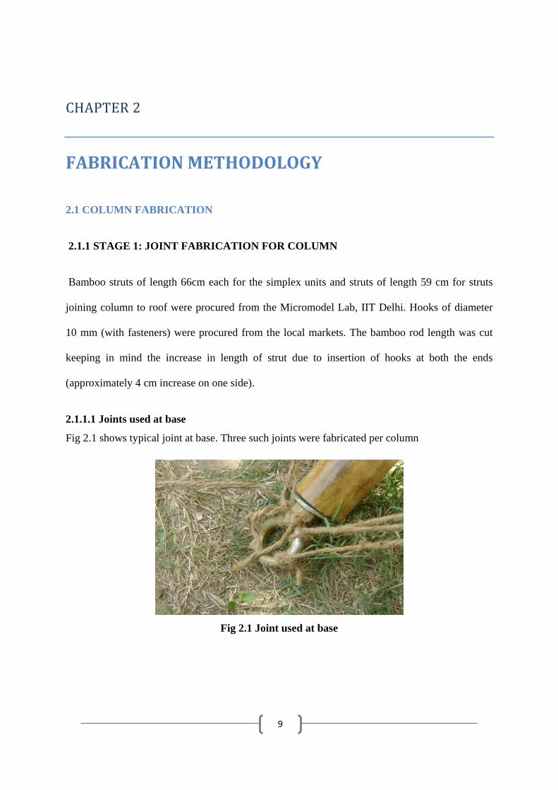
2.1.1.1 Joints used at base
Fig 2.1 shows typical joint at base. Three such joints were fabricated per column
Fig 2.1 Joint used at base

10
For this type of joint, first the hole at the end of the bamboo was filled with epoxy adhesive. The
epoxy was prepared by mixing the components- hardener and resin, as shown in Fig 2.2. Then, a
single hook end was inserted into the bamboo hole and the fastener was expanded using pliers till
it expanded equal to the hole diameter. The hook was then pushed in after application of epoxy
to the washer to ensure against leakage of adhesive. Then they were kept for 24 hours as epoxy
takes time to cure.
Fig 2.2 Epoxy and hardener
2.1.1.2 Joints used in the middle
Fig 2.3 shows a typical middle joint
Fig 2.3 Joint used in the middle

11
For this type of joint, two hooks were first connected to each other. This was done by bending
one of the hooks and then inserting the other hook into it. After this, one hook was inserted into a
bamboo which either had a base joint or joint connecting to roof at opposite end and another
hook was inserted into a bamboo with middle joint at the opposite end. The joint fabrication
procedure was as above. They were then left to cure for 24 hours.
2.1.1.3 Joints used for connecting to roof
These joints shown in Fig 2.4 were situated at the top of column. One such joint was fabricated
per column.
Fig 2.4 Joint used for connecting column to roof
For this type of joint three hooks were connected to each other. This was done by bending one of
the hooks and then inserting another hook into it and repeating this for one more hook. After this,
the hooks were inserted into a bamboo which had a middle joint at opposite end. The joint
fabrication procedure was as above. They were then left to cure for 24 hours.

12
2.1.2 STAGE 2: CABLE FABRICATION FOR COLUMN
Ropes of length 58 cm were cut for the base and top triangle of the simplex unit. This was done
keeping 5 cm on each side to tie knots. Side length was supposed to be 50 cm but actual length
was kept 48 cm as the rope elongates when put under tension and elongation was found to be
around 2 cm. Similarly ropes of length 60.2 cm were cut to connect base to top of simplex unit.
2.1.3 STAGE 3: FINAL COLUMN FABRICATION
Finally, struts were joined with cables to give one unit of simplex as shown in the Fig 2.5, which
were then joined to produce one column as shown in the Fig 2.6. Similarly, three other units
were fabricated. Height of each simplex module was 0.5 m and total height of a column was
1.6m.
Fig 2.5 Simplex Unit Fig 2.6. Complete column

13
2.2 ROOF FABRICATION
2.2.1 STAGE 1: JOINT FABRICATION FOR ROOF
Bamboo rods of length 90cm each were procured from the Micromodel Lab, IIT Delhi.
Hooks of diameter 10 mm (with fasteners) were procured from the local markets. The bamboo
rod length was cut keeping in mind the increase in length of strut due to insertion of hooks at
both the ends (approximately 4 cm increase on one side).
2.2.1.1 Joints used at top of roof
These joints, shown in Fig 2.7, were used at top of roof. Sixteen such joints were fabricated for
the roof
Fig 2.7. Joints used at top of roof
For this type of joint, first the hole at the end of the bamboo was filled with epoxy adhesive.
Then, a single hook end was inserted into the bamboo hole and the fastener was expanded using
pliers till it expanded equal to the hole diameter. The hook was then pushed in after application
of epoxy to the washer to ensure against leakage of adhesive. Then they were kept for 24 hours
for curing.

14
2.2.1.2 Joints used in the middle of the roof base
These joints as shown in Fig 2.8, were used in the middle. Four such joints were fabricated per
for the roof.
Fig 2.8. Joints used in the middle of the roof base
For this type of joint, two hooks were first connected to each other. This was done by bending
one of the hooks and then inserting the other hook into it. After this, one hook was inserted into a
bamboo which had a roof top joint at the opposite end. The joint fabrication procedure was as
above. They were then left to cure for 24 hours.
2.2.1.3 Joints used at centre of roof
These joints as shown in Fig 2.9 , were used at the centre of the roof. One such joint was
fabricated for the roof.
Fig 2.9. Joints used at centre of roof

15
For this type of joint four hooks were connected to each other. This was done by bending one of
the hooks and then inserting another hook into it and repeating this for two more hooks. After
this, the hook was inserted into a bamboo which had a roof top joint at the opposite end. The
joint fabrication procedure was as above. They were then left to cure for 24 hours.
2.2.1.3 Joints used for connecting to column
These joints, shown in Fig 2.10 , were at the four corners of the roof. Four such joints were
fabricated for the roof.
Fig 2.10. Joints used for connecting to column
For this type of joint first the hole at the end of the bamboo was filled with epoxy adhesive. .
Then a single hook end (which had already been bent open) was inserted into a bamboo which
had a roof top joint at the other end. The joint fabrication procedure was as above. They were
then left to cure for 24 hours.
2.2.2 STAGE 2: CABLE FABRICATION FOR ROOF
Ropes of length 85 cm were cut for the base and of length 47.5cm for the top square of the Half-
cuboctahedron unit. This was done keeping 5 cm on each side to tie knots. Side length was

16
supposed to be 75 cm but actual length was kept 83 cm as the rope elongates when put under
tension and elongation was found to be around 2 cm.
Similarly ropes of length 70.5 cm were cut to connect base to top of Half-cuboctahedron unit.
2.2.3 STAGE 3: FINAL ROOF FABRICATION
Finally, struts were joined with cables to form one half-cuboctahedron unit as in Fig 2.11 which
were joined to form the roof as shown in the Fig 2.12. The roof has square dimensions of 1.5m
x1.5m and a height of 0.5m.
Fig.2.11.Half Cuboctahedron Unit Fig 2.12.Complete Roof

17
2.3 JOINING OF COLUMS WITH ROOF TO COMPLETE FINAL STRUCTURE
In the end the roof was joined with the four columns at the four corners as shown in the Fig 2.13.
This was done by inserting the open hooks at the four base corner joints of the roof into the
topmost joints of the column and then securing the joint by tying it with rope.
Fig 2.13.Final Shed Structure

18
Chapter 3
Preliminary Analysis 3.1. TESTING OF CABLES AND STRUTS
3.1.1.Testing of Bamboo Struts
The Bamboo struts were tested for compression in the UTM as shown in Fig 3.1.Bamboo
specimens of 18cm (L/R<10) were tested and the average compressive strength from several
tests came out to be 57.5 MPa.
Fig 3.1.UTM used for testing bamboo Struts
3.1.1. Testing of jute ropes
The jute rope was tested for tensile strength by tying it to a spring balance and suspending
weights from the other end as shown in Fig 3.2.The average tensile strength came out to be
122.5N

19
Fig 3.2.Spring Balance used for testing jute rope
3.2. CHECK FOR ADEQUACY OF MEMBERS
Typical forces in a tensegrity based shed structure similar to the one fabricated are (Singh, R.P.,
2009) in the range of 90 to 120 N for normal wind conditions and in the range of 700 N for worst
cases.
Thus we can observe that the members have strengths that are more than required for normal
wind conditions and thus we can conclude that the structure has an adequate factor of safety.
However for the worst case scenario the loads are of the range 700N, therefore we should use
much stronger elements (mainly cables) in case we are expecting worst case conditions.
20
CHAPTER 4
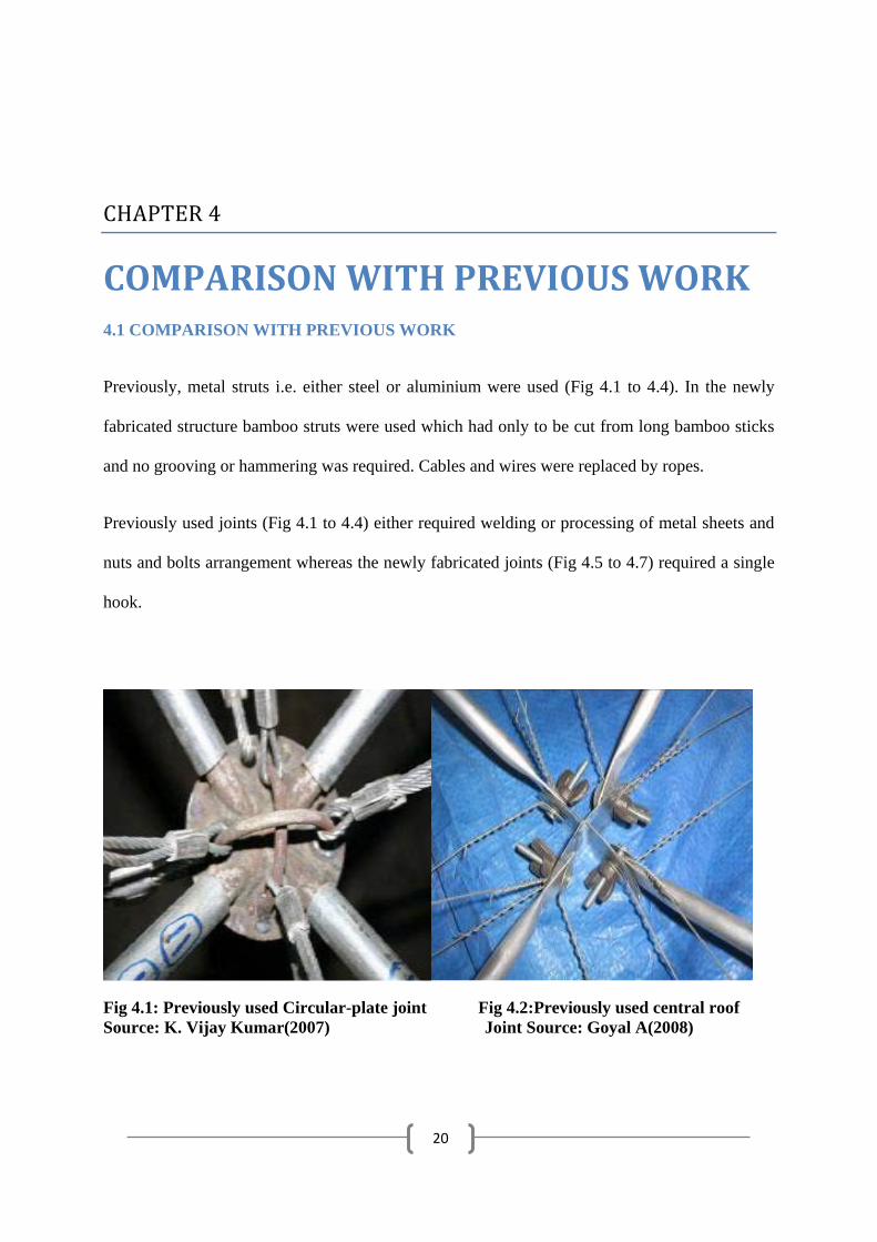
COMPARISON WITH PREVIOUS WORK 4.1 COMPARISON WITH PREVIOUS WORK
Previously, metal struts i.e. either steel or aluminium were used (Fig 4.1 to 4.4). In the newly
fabricated structure bamboo struts were used which had only to be cut from long bamboo sticks
and no grooving or hammering was required. Cables and wires were replaced by ropes.
Previously used joints (Fig 4.1 to 4.4) either required welding or processing of metal sheets and
nuts and bolts arrangement whereas the newly fabricated joints (Fig 4.5 to 4.7) required a single
hook.
Fig 4.1: Previously used Circular-plate joint Fig 4.2:Previously used central roof Source: K. Vijay Kumar(2007) Joint Source: Goyal A(2008)
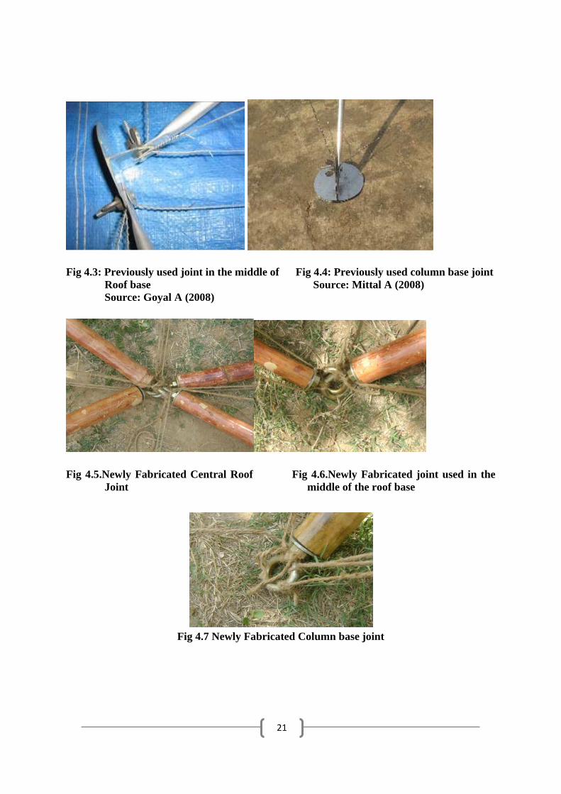
21
Fig 4.3: Previously used joint in the middle of Fig 4.4: Previously used column base joint Roof base Source: Mittal A (2008) Source: Goyal A (2008)
Fig 4.5.Newly Fabricated Central Roof Fig 4.6.Newly Fabricated joint used in the Joint middle of the roof base
Fig 4.7 Newly Fabricated Column base joint
22
Some of the advantages of the new structure over previous ones are listed below
1. Minimum processing of struts required.
2. No welding or nuts and bolts arrangement required in fabrication.
3. More flexible than previous structures.
4. Dismountable and easily storable.
5. No complex procedure when connecting cables as only a knot has to be tied.
6. Structure much lighter than some of the previous structures.
7. Much more environment friendly as compared to any of the previous structures and much
more viable for rural areas.
8. More economical.

23
CHAPTER 5
CONCLUSIONS AND RECOMMENDATIONS
5.1. CONCLUSIONS
The main conclusions drawn from the project are-
There is great potential of the combination of bamboo and tensegrity in the construction
industry.The fabricated structure aims to provide an alternative environment friendly
construction for a steel poultry shed. It can serve multiple purposes, such as workshop for a
cottage industry, warehouse, and other medium industries. Not only is the structure light
compared to conventional steel, it is at the same time several times cheaper and eco friendly.
Such structures can pave way for sustainable industrialization of the rural sector in India and
other developing nations.
5.2. RECOMMENDATIONS
Some of the recommendations for further research in fabrication of bamboo based tensegrity
sheds are-
1. Instead of jute rope nylon rope should be used as cable. This is due to the fact that jute
ropes are not very durable and break easily after they come in contact with water i.e. after
it rains. Another problem with jute ropes is their high and variable elasticity.
2. Bamboo of the lightest type available should be used so as to keep the dead load on
structure small.
24
REFERENCES Goyal A(2008), Fabrication of Prototype Dismountable Half-Cuboctohedron Roof for Shed
Structures, Mini Project Report, Department of Civil Engineering, IIT Delhi
Bhalla et al.(2008), Bamboo As Green Alternative To Concrete And Steel For Modern Structures
Mittal A(2008), Fabrication of Prototype Dismountable Simplex Column for Shed
Structures, Mini Project Report, Department of Civil Engineering, IIT Delhi
Kumar K V(2007), Dynamic Characterization of Tensegrity Structures, M.Tech
Project Thesis, Department of Civil Engineering, IIT Delhi
Singh, R.P.(2009), Health Monitoring of Structures using Piezo-Transducers, M.Tech
Project Thesis, Department of Civil Engineering, IIT Delhi
Online Resources:
Snelson, K.(2009)
http://www.kennethsnelson.net/, accessed January 2009-May 2009