tender specification no.01/2016-17 -...
TRANSCRIPT

1
CENTRAL ELECTRICITY SUPPLY UTILITY OF
ODISHA
OFFICE OF THE GENERAL MANAGER (ELECT.)
ELECTRICAL CIRCLE, DHENKANAL
TENDER SPECIFICATION NO.01/2016-17 CESU/SEEC-DKL/DEPOSIT SCHEME/2016-17
TURNKEY CONTRACT (SUPPLY & ERECTION)
FOR
CONSTRUCTION OF LINE, SUB-STATION & DISMANTLE OF EXISTING LINES & SUB-STATION FROM MINING AREA OF PROJECT OFFICER, HINGULA OCP, MCL AT VILLAGE PURUNAPANI TO VILLAGE BHALUGADIA UNDER BALANDA SECTION OF TED CHAINPAL IN 100% DEPOSIT WORK SCHEME
ON TURNKEY BASIS.

2
CENTRAL ELECTRICITY SUPPLY UTILITY OF ODISHA OFFICE OF THE GENERAL MANAGER (ELECT.)
ELECTRICAL CIRCLE: DHENKANAL, COLLEGE BYPASS CHHAK,NH-55, DHENKANAL ���� 06762 – 243353, FAX – 243015, [email protected]
Tender Call Notice No.01/2016-17 Tender Call Notice for construction of 11KV line –1.2Km.< Line in AB Cable-1.4Km., shifting of 11/0.4KV,100KVA Sub-Station -1No,installation of 11/0.4KV,25 KVA S/S =1 No, construction of road crossing 11KV line DP with provision of guarding-1span and installation of 3 Nos. 400 Amp (H type) AB switch, laying of 2X3 core 400mm2 11KV XLPE UG cable with spare through cable trench made up of GI pipe of with DP structure towards shifting of existing lines & sub-station in order to initiate excavation & mining related work of MCL under Balanda Section under Talcher Electrical Division on ‘Turnkey’ under Deposit scheme.
For and on behalf of CESU the undersigned invites sealed bids in duplicate on two part bidding system from qualified and eligible bidders, who comply to the terms and conditions for the following works on turn-key /single source basis in Deposit scheme.
Brief Description of Work
Total estimated
Tender value (Rs)
EMD (Rs)
Last date/tim
e for submissi
on of bids
Date and time of opening of bid
Cost of Tender Paper
including VAT@5%
1 2 3 4 5 6
1. Shifting of 100KVA ,11/0.4 KV pole mounted Substation =1 No. using 9 mtr long 300Kg. PSC Pole
2. Construction of 25KVA ,11/0.4 KV Pole mounted Substation = 1 Nos. using 9 mtr long 300Kg. PSC Pole
3. Construction of 3Ø3W 11 KV line using
10mtrs long 100 x 116mm RS joist pole with 80mm2 AAAC having span length 70mtr = 1.2 CKm
4. Construction of 3Ø4W LT line using 8mtr long 200 Kg PSC Pole with 3X50+1X35mm2 AB cable having span length 40 mtr = 1.4 CKm
5. Construction of 11KV line DP with 10Mtr. long 100X116 RS Joist for 11KV line with provision for guarding & installation of 11KV
400 Amp H type line AB switch = 3 Nos.
6. Laying of 2X3 Core 11KV XLPE UG Cable with spare through HDD method = 320 Mtr.
7. Construction of DP structure for cable rising = 2 Nos.
8. Extra labour charges for cable laying work
9. Dismantling of 11/0.4KV 100KVA S/S=1 No.
10. Dismantling of 11/0.23KV 10KVA S/S=1 No.
11. Dismantling of 3Ø3W 11KV line = 2.2 Km
39,37,239.00
EM
D @
1%
of
the t
ota
l esti
mate
d T
en
der
valu
e i.e R
s 3
9,3
72/-
to
be d
eposit
ed
in S
hape o
f D
em
an
d D
raft
in f
avour
of
CE
SU
,
ELE
CT
RIC
AL C
IRC
LE
DH
EN
KA
NA
L p
ayable
at
Dhenkanal
18.0
8.2
016 A
t.12.0
0 N
oon
18.0
8.2
016 A
t- 3
.00PM
6,3
00.0
0
Sale and downloading of tender documents starts from Dt. 05.08.2016 to Dt. 17.08.2016(During office working hours). For details please Visit
our Web site www.cescoorissa.com. The authority reserves the right
to accept or reject any or whole of the offers without assigning any reason thereof.
Sd/- General Manager (Elect.)
Electrical Circle Dhenkanal

3
SECTION - I
INFORMATION TO BIDDERS (IFB) Tender Notification:

4
1.0 CESU invites sealed tenders from reputed Electrical Contractors with required
license, either in individual capacity or as part of a joint venture agreement / consortium for carrying out various Electrical Installation works on ‘Turnkey’ basis in the jurisdiction of their respective licensed area. The bidder must fulfill all the qualification requirements as specified in clause 2.0 stated below. The sealed envelopes shall be duly super scribed as “TENDER NOTICE No: 01/2016-17 and Due date of opening 18.08.2016.
Brief Description of Work
Total estimated
Tender value (Rs)
EMD (Rs)
Last date/tim
e for submissi
on of bids
Date and time
of opening of bid
Cost of Tender Paper
including VAT@5%
1 2 3 4 5 6
a) Shifting of 100KVA ,11/0.4 KV pole mounted Substation =1 No. using 9 mtr
long 300Kg. PSC Pole
b) Construction of 25KVA ,11/0.4 KV Pole mounted Substation = 1 Nos. using 9 mtr
long 300Kg. PSC Pole
c) Construction of 3Ø3W 11 KV line using 10mtrs long 100 x 116mm RS joist pole with 80mm2 AAAC having span length 70mtr = 1.2 CKm
d) Construction of 3Ø4W LT line using 8mtr long 200 Kg PSC Pole with 3X50+1X35mm2 AB cable having span
length 40 mtr = 1.4 CKm
e) Construction of 11KV line DP with 10Mtr. long 100X116 RS Joist for 11KV line with provision for guarding & installation of 11KV 400 Amp H type line AB switch = 3 Nos.
f) Laying of 2X3 Core 11KV XLPE UG Cable with spare through HDD method = 320
Mtr.
g) Construction of DP structure for cable
rising = 2 Nos.
h) Extra labour charges for cable laying work
i) Dismantling of 11/0.4KV 100KVA S/S=1
No.
j) Dismantling of 11/0.23KV 10KVA S/S=1
No.
k) Dismantling of 3Ø3W 11KV line = 2.2 Km
39,37,239.00
EM
D @
1%
of
the t
ota
l esti
mate
d T
en
der
valu
e
i.e R
s.
39,3
72/-
to b
e
deposit
ed
in S
hape o
f D
em
an
d D
raft
18.0
8.2
016
18.0
8.2
016 A
t- 3
.00PM
6,3
00.0
0
2.0 Bidders to be considered as eligible (to bid) should meet the following qualifications; (a) Bidder must quote for the entire quantum of works specified in the project (b) Bidder should have installed and commissioned at least 100% of the similar quantum of works as specified in the project scope ( GCC Cl-2 ) under scope of work) for which the bidder is submitting his bid during the last three financial years preceding to the year of tender notification. Bidder must enclose copies of the relevant Work Orders along with Client Certified copies of Final Invoices and/or Performance Certificates duly signed by the competent authority of the client and/or Final Inspection Certificate issued by Electrical Inspector in proof of having executed the desired quantum works during the last three financial years as per the format prescribed on VII(A) / VII (B) or applied.
(c) Average Annual Turnover during the last three financial years preceding to the year of tender notification shall not be less than Two times the estimated cost of the project for which the bidder has submitted his bid.

5
(d) Bidder shall be financially sound and stable having liquid assets as stated in the enclosed format and/or access to credit facility of not less than one fifth of estimated cost of the package(s) for which he has submitted the bid. (e) In addition to above the bidder should submit the following documents in part-I bid as qualifying terms.
i. Valid electrical (HT) license for electrical works. ii. EPF registration iii. ESI registration iv. Service Tax registration v. VAT Clearance Certificate vi. PAN & TIN No. vii. Existing Labour license viii. Income tax clearance certificate ix. The bidders who have earlier failed to execute the work order(s) of
CESU shall not be eligible to participate in this tender. x. CESU reserves the right to waive minor deviation, if they do not
materially effect the capacity of the bidder to perform the contract. 3.0 Bids specification document can be obtained from the office of the undersigned on
payment of ` 6,000/- towards non-refundable cost of bid documents plus 5% VAT (Total `6,300/-) through Bank D.D drawn in favour of CESU, ELECTRICAL CIRCLE
DHENKANAL payable at Dhenkanal, during office hours from 11.00 am to 3.00 pm till dt. 17.08.2016. 4.0 The tender documents can also be downloaded from our website www.cescoorissa.com. In case tender papers are downloaded from these websites, then the bidder has to enclose a Demand Draft, drawn on any scheduled bank, payable at Dhenkanal, covering the cost of bid documents as stated above in a separate envelope with suitable superscription “Cost of Bid Documents : Tender Notice Ref No. This envelope should accompany the Bid Documents. 5.0 The Bids shall be submitted in the office of the undersigned on all office working days up to 12.00 hrs of Date 18.08.2016. In the event the date of opening is a holiday, the next working day shall be treated as the date of opening. 6.0 Part-I of the bid (Technical Bid) will be opened on dt. 18.08.2016 at 15.00 hrs & Part-II of the bid (Price Bid) will be opened on dt. 18.08.2016 at 16.00hrs as indicated above, in the presence of the authorized representatives of the Bidders. Bidders shall depute only one representative to attend pre bid meeting and tender opening if they wish to be represented. The undersigned reserves the right to reject any or all tenders if the situations so warrants. 7.0 All correspondence with regard to the above shall be made to the following address:
GENERAL MANAGER (ELECTRICAL) ELECTRICAL CIRCLE DHENKANAL, CESU College By-pass Chhak, P.O/Dist – Dhenkanal, PIN-759001 Phone – 06762 – 243353 [email protected]
Sd/- General Manager (Elect)
Electrical Circle, Dhenkanal

6
SECTION - II
GENERAL CONDITIONS OF CONTRACT (GCC)

7
1.0 GENERAL: - CESU, hereinafter referred to as the “Owner” are desirous of construction of 11KV – 1.2 CKm. & LT Line in AB Cable-1.4CKm., shifting of 11/0.4 KV 100KVA Sub-Station -1No, installation of 25 KVA S/S =1 No, construction of road crossing 11KV line DP with provision of guarding 1 span and installation of 3 Nos. 400 Amp (H type) AB switch, laying of 2X3 core 400mm2 11KV XLPE UG cable with spare through cable trench made up of GI pipe of with DP structure towards shifting of existing lines & sub-station in order to initiate excavation & mining related work of MCL under Balanda Section under Talcher Electrical Division on ‘Turnkey’ under deposit scheme.
The Bidder shall ensure to follow the instructions given here under failing which the tender shall be liable for rejection. 2.0 SCOPE OF WORK: -
2.1 Shifting of 100KVA ,11/0.4 KV pole mounted Substation =1 No. using 9 mtr long 300Kg. PSC Pole
2.2 Construction of 25KVA ,11/0.4 KV Pole mounted Substation = 1 Nos. using 9 mtr long 300Kg. PSC Pole
2.3 Construction of 3Ø3W 11 KV line using 10mtrs long 100 x 116mm RS joist
pole with 80mm2 AAAC having span length 70mtr = 1.2 Ckt Km.
2.4 Construction of 3Ø4W LT line using 8mtr long 200 Kg PSC Pole with
3X50+1X35mm2 AB cable having span length 40 mtr=1.4 Ckt Km.
2.5 Construction of 11KV line DP with 10Mtr. long 100X116 RS Joist for 11KV line with provision for guarding & installation of 11KV 400 Amp H type line AB
switch = 3 Nos.
2.6 Laying of 2X3 Core 11KV XLPE UG Cable with spare through HDD method = 320 Mtr.
2.7 Construction of DP structure for cable rising = 2 Nos.
2.8 Extra labour charges for cable laying work
2.9 Dismantling of 11/0.4KV 100KVA S/S=1 No.
2.10 Dismantling of 11/0.23KV 10KVA S/S=1 No.
2.11 Dismantling of 3Ø3W 11KV line = 2.2 Km
The scope covers supply and installation of materials, which are not available in departmental store (OSM) & equipments to complete the works including the following:
i. Complete manufacture, including shop testing & supply of materials from the approved vendor (materials which are to be supplied by the bidder)
ii. Providing Engineering drawing, data, operational manual, etc for the Purchaser’s approval.
iii. Packing and transportation from the manufacturer’s works to the site. iv. Receipt, storage, preservation and conservation of equipment at the site. v. Pre-assembly, if any, erection testing and commissioning of all the equipment; vi. Reliability tests and performance and guarantee tests on completion of
commissioning; vii. Loading, unloading and transportation as required. viii. Erection of lines of specified voltage. ix. Testing, Commissioning of lines / installations x. Storing before erection xi. Getting the lines inspected by Electrical Inspector after completion of work. xii. Transportation and transit insurance of all free issue materials to be supplied
from Purchaser’s nearest stores to site and as well as all other required materials (under the scope of supply by bidder) from supplier’s premises to work site, construction of new electrical / civil structures, etc.
3.0 DEFINITION OF TERMS (i) The ‘Contract ’means the agreement entered into between the Owner and the
Contractor as per the Contract Agreement signed by the parties, including all attachments and appendices there to and all documents incorporated by reference therein.
(ii) ‘Owner’ shall mean CESU and shall include its legal representatives, successors and assigns.
(iii) Contractor’ shall mean the Bidder whose bid will be accepted by the Owner for

8
the award of the Works and shall include such successful Bidder’s legal representatives, successors and permitted assigns.
(iv) Engineer in Charge’ shall mean the officer appointed in writing by the Purchaser to act as Engineer from time to time for the purpose of the Contract.
(v) ‘Specifications’ shall mean the specifications and Bidding Document forming a part of the Contract and such other schedules and drawings as may be mutually agreed upon.
(vi) ‘Site’ shall mean and include the land and other places on, into or through which the works and the related facilities are to be erected or installed and any adjacent land, paths, street or reservoir which may be allocated or used by the Purchaser or Contractor in the performance of the Contract.
(vii) Inspector’ shall mean the Owner or any person nominated by the Owner from time to time, to inspect the equipment; stores or Works under the Contract and/or the duly authorized representative of the Owner.
(viii) Notice of Award of Contract’/ ‘Letter of Award’ shall mean the official notice issued by the Owner notifying the Contractor that his bid has been accepted.
(ix) Date of Contract’ shall mean the date on which notice of Award of Contract/ Letter of Award has been issued.
(x) Performance and Guarantee Tests’, shall mean all operational checks and tests required to determine and demonstrate capacity, efficiency, and operating characteristics as specified in the Contract Documents.
(xi) The term ‘Final Acceptance’/ ‘Taking Over’ shall mean the Purchaser’s written acceptance of the works performed under the Contract, after successful commissioning/ completion of Performance and Guarantee Tests, as specified in the accompanying Technical Specifications or otherwise agreed in the contract.
(xii) Commercial Operation’ shall mean the condition of operation in which the complete equipment covered under the Contract is officially declared by the Purchaser to be available for continuous operation at different loads up to and including rated capacity. Such declaration by the Purchaser, however, shall not relieve or prejudice the Contractor of any of his obligations under the Contract.
(xiii) Words imparting ‘Person’ shall include firms, companies, corporations and associations or bodies of individuals, whether incorporated or not.
(xiv) Terms and expressions not herein defined shall have the same meaning as are assigned to them in the Indian Sale of goods Act (1930), failing that in the Indian Contract Act (1872) and failing that in the General Clauses Act (1897) including amendments thereof, if any.
(xv) In addition to the above the following definition shall also apply
a) All equipment and materials’ to be supplied shall also mean ‘Goods’ b) Constructed’ shall also mean erected and installed. c) Contract Performance Guarantee’ shall also mean ‘Contract Performance
Security’. 3.0 SUBMISSION OF TENDER: - 3.01 Sealed tenders in Two parts each in duplicate, each complete in all respects in the manner hereinafter specified are to be submitted in the OFFICE OF GENERAL MANAGER (ELECTRICAL) ELECTRICAL CIRCLE DHENKANAL on or before the date and time specified in the notice inviting the tenders. Bids shall be submitted as per format provided in Section – III & IV. 3.02 The tenders are required to be submitted in Two Parts each in separate double
sealed covers. � Part-I:Super scribed as “Technical and Commercial Bid ” shall contain EMD, Cost of
Bid Documents and Techno commercial documents. � Part-II: Super scribed as “ Price Bid”. The Part -II should contain only Price bid.
3.03 Fax and Telegraphic tenders shall not be accepted at no cost. 3.04 Receipt of bids/ revised bids after the cut off time and date as specified in the
Tender Notice shall not be permitted and such bids shall be rejected outright. The Owner shall not be responsible for any delay in transit in post / courier etc. in this regard.
4.0 VALIDITY :- The offer shall be valid for a period not less than 180 days from the date of bid opening.

9
5.0 PRICE: - Bidders are required to quote firm price as per the prescribed format enclosed in Section – IV. The quoted price shall be firm and inclusive of all taxes, duties, freight & insurance and other levies, if any. CESU shall not be liable to pay anything extra over and above the quoted price. 6.0 RECEIPT AND OPENING OF THE BID : - 6.01 Bids in as described under clause 4.0 shall be received in the office of the Owner and shall be opened on the scheduled date and time. The Owner’s authorized representatives shall open bids in the presence of Bidders’ representatives on the date and time for opening of bids as specified in the Invitation to Bid or in case any extension has been given thereto, on the extended bid opening date and time notified. 6.02 Maximum one representative for each bidder shall be allowed to witness the opening of bids. The representative must produce suitable authorization in this regard to be eligible to witness the bid opening on behalf of the bidder. Bidders’ representatives who are present shall sign in a register evidencing their attendance. 6.03 The Bidders’ names, bid prices, modifications, bid withdrawals and the presence or absence of the requisite bid guarantee and such other details as the Purchaser, at its discretion, may consider appropriate will be announced at the opening. No electronic recording devices will be permitted during bid opening. 6.04 Information relating to the examination, clarification, evaluation and comparison of Bids and recommendations for the award of a contract shall not be disclosed to Bidders or any other persons not officially concerned with such process. Any effort by a Bidder to influence the Owner's processing of Bids or award decisions may result in the rejection of the Bidder's Bid. 7.0 EVALUATION OF BIDS & AWARD OF CONTRACT : 7.01 To assist in the examination, evaluation and comparison of Bids, the Owner may, at its discretion, ask the Bidder for a clarification of its Bid. All responses to requests for clarification shall be in writing and no change in the price or substance of the Bid shall be sought, offered or permitted. 7.02 Owner will examine the Bids to determine whether they are complete, whether any computational errors have been made, whether required sureties have been furnished, whether the documents have been properly signed, and whether the Bids are generally in order. 7.03 Arithmetical errors will be rectified on the following basis. If there is a discrepancy between the unit price and the total price per item that is obtained by multiplying the unit price and quantity, the unit price shall prevail and the total price per item will be corrected. If there is a discrepancy between the Total Amount and the sum of the total price per item, the sum of the total price per item shall prevail and the Total Amount will be corrected. In case the bidder quoted the unit price as “NIL/BLANK”, the same is read as inclusive of total price. Accordingly, the bidder shall execute the said work without any Financial burden to CESU. 7.04 Prior to the detailed evaluation, Owner will determine the substantial responsiveness of each Bid to the Bidding Documents including production capability and acceptable quality of the Goods offered. A substantially responsive Bid is one, which conforms to all the terms and conditions of the Bidding Documents without material deviation. 7.05 The Owner's evaluation of a Bid will take into account, in addition to the Bid price, the following factors, in the manner and to the extent indicated in this Clause:
(a) Work Schedule (b) Deviations from Bidding Documents
7.06 The Owner will award the Contract to the successful Bidder whose Bid has been determined to be the lowest - evaluated responsive Bid,, when the lowest bidders is not ready and/or capable to undertake the entire work envisaged, then the Purchaser may explore the possibility of the execution of works through other bidders if they are willing to execute at L1 rate. Such exploration shall be carried out in a sequential order starting with L2 bidder then with L3 bidder and so on. 8.0 EARNEST MONEY DEPOSIT (EMD):- 8.01 The Tender must be accompanied by Earnest Money Deposit in shape of account payee Bank Draft drawn on any scheduled bank in favour of “CESU ELECTRICAL CIRCLE DHENKANAL” payable at DHENKANAL. EMD shall be 1% of the total estimated Tender
value i.e ` 39,372/- for this project. Bids without EM deposit will be rejected out rightly.
The EMD should be deposited in the manner specified in the detail tender Notice.
10
8.02 No adjustment of any previous deposit or any amount payable from Purchaser shall be entertained for EMD. EMD amount so submitted shall not carry any interest payable to the bidder. 8.03 The Earnest Money so deposited shall be forfeited:
(a) if the Bidder: i) withdraws its bid during the period of bid validity specified by the Bidder in
the Bid Form; or (b) in the case of a successful Bidder, if the Bidder fails:
(i) to sign the Contract, or (ii) to furnish the required Contract Performance Bank Guarantee.
8.04 The EMD of unsuccessful bidders shall be returned within 30 days from the date of finalization of the Tender. 9.0 OWNER’S RIGHT TO VARY QUANTITIES AT TIME OF AWARD:
While placing orders and / or during execution of contract, Owner reserves the right to increase or decrease the quantity of goods and services specified in the Schedule of Requirement up to 20% of the tender quantity without any change in price or other terms and conditions. 10.0 INSPECTION AND TESTING :- The Engineer-in-charge shall be entitled at all reasonable times during manufacture / installation to inspect, examine and test the materials at the contractor’s premises / erection site about workmanship of the materials to be supplied under this contract. If the said materials are being manufactured in other premises, the contractor shall provide unhindered clearance, giving full rights to the purchaser to inspect, examine and test as if the materials were being manufactured in his premises. Such inspection / examination and testing shall not relieve the contractor of his obligations to execute the contract by letter and spirit. The contractor shall give the purchaser advance notice in writing of the Date and the Place at which the materials will be ready for testing. The inspecting officer for the entire work shall be the (Respective Purchaser Authority) of the concerned site. 11.0 COMPLETION AND COMPLETENESS OF THE EQUIPMENT :- 11.01 Time being the essence of the contract; the work shall be completed within 60 days from the date of issue of work order. 11.02 The work shall be treated as complete item wise when one item shall be complete in all respects with all mountings, fixtures and standard accessories which are normally supplied even though not specifically detailed in the specification. No extra payment shall be payable for such mounting, fittings, fixtures and accessories which are needed for safe operations of the equipment as required by applicable code of the country though this might not have included in the contract. 11.03 All similar components and/or parts of similar equipment supplied shall be inter-changeable with one another. Various equipments supplied under this contract shall be subject to Purchaser’s approval. 11.04 Purchaser however reserves the right to re-schedule the completion period, if required. 12.0 REJECTION OF MATERIALS : - In the event of the materials supplied by the contractor and/or the installation works are found to be defective in quality and the workmanship is poor or otherwise not in conformity with the requirements of the contract specification as per section-IV (Technical specification), Owner shall reject such materials/services and ask the contractor in writing to replace/rectify the defects. The contractor on receipt of such notification shall either rectify or replace the defective materials and/or re-install the work already executed, free of cost to the Purchaser. If the contactor fails to do so the Purchaser may at his option take the following actions which could be on concurrent basis.
A) Replace or rectify such defective materials and recover the extra cost so involved plus 25% from the Contractor.
B) Terminate the contract for balance supply and erection with enforcement of penalty as per contract.
C) Acquire the defective materials at reduced price considered acceptable under the circumstances.
D) Forfeit the Contract Performance Bank Guarantee. 13.0 EXPERIENCE OF BIDDERS : - The bidders are required to furnish information regarding their experience on the following aspects as per format provided in Section – IV, Annexure VII (A) & (B) :
i. Description of similar type of work executed during the last three years with the name(s) of the party(s) to whom / where supplies / erection were made.

11
ii. Testing facilities available at manufacturer’s works along with the list of testing equipments.
iii. work orders details (W.O No. and date only) executed (construction work) during the last three years along with Electrical inspection report copies and copies of user’s performance certificates.
Bids may not be considered if the past performance is found to be un-satisfactory. 14.0 DEVIATION FROM SPECIFICATION: - The bidders are requested to study the specification and the attached drawings thoroughly before tendering so that if they make any deviations, the same are prominently brought on a separate sheet under the headings “Deviations” as per formats provided under Section IV, Annexure – VIII & IX. All such deviations to the technical & commercial terms of the specification shall be indicated in a separate list as indicated above. In absence of such deviation schedule, it will be presumed that the bidder has accepted all the conditions stipulated in the tender specification, not withstanding any deviations mentioned elsewhere in the Bid. However the acceptance of deviation is not binding on the Purchaser. 15.0 GUARANTEE PERIOD: - 15.01 The materials to be supplied by contractor shall be guaranteed for satisfactory operation against defects in design and workmanship for a period of 24monts from the date of handing over the completed installations. 15.02 The above guarantee certificate shall be furnished in triplicate to the Owner for his approval. Any defects noticed during the above period should be rectified by the Contractor free of cost to the Utility provided such defects are due to faulty design, bad workmanship or bad materials used on receipt of written notice from the Purchaser. 16.0 PENALTY FOR DELAY IN COMPLETION OF CONTRACT: - 16.01 If the contractor fails to complete the works by the scheduled period or any extension granted thereby, the contractor shall be liable for payment of penalty amounting to 0.5% (half percent) of the contract price per week of un-finished works subject to the maximum of 5% (five percent) of the total contract price and subject to force majeure conditions. 16.02 Penalty amount can be realized from the proceeds of the Contract Performance Bank Guarantee, if the situation so warrants. 16.03 Extension of delivery period could be with / without levy of penalty with the discretion of purchaser. 17.0 RIGHT OF WAY : Right of way issues, if any, arising during execution of the works shall have no liability on the Owner. These issues shall be settled at the sole discretion of the Contractor. The Owner shall however extend all possible help to the Contractor including discussion with the local authorities for early resolution of these issues. 18.0 CONTRACTOR’S DEFAULT : 18.01 If the Contractor neglects to execute the works with due diligence and expedition or refuses or neglects to comply with any reasonable order given to him, in writing by the Engineer in connection with the works or contravenes the provisions or the contract, the Owner may give notice in writing to the Contractor to make good the failure, neglect or contravention complained of. Should the Contractor fail to comply with the notice within thirty (30) days from the date of serving the notice, the Owner shall be at liberty to employ other workmen and forthwith execute such part of the works as the contractor may have neglected to do or if the Owner thinks fit, without prejudice to any other right, he may have under the Contract to take the work wholly or in part out of the Contractor’s hands and re-contract with any other person or persons to complete the works or any part thereof and in that event the Owner shall have free use of all Contractor’s equipment that may have been at the time on the Site in connection with the works without being responsible to the Contractor for fair wear and tear thereof and to the exclusion of any right of the Contractor over the same, and the Owner shall be entitled to retain and apply any balance which may otherwise be due on the Contract by him to the Contractor, or such part thereof as may be necessary, to the payment of the cost of executing the said part of works or of completing the works as the case may be. If the cost of completing of works or executing part thereof as aforesaid shall exceed the balance due to the Contractor, the Contractor shall pay such excess. Such payment of excess amount shall be independent of the liquidated damages for delay which the Contractor shall have to pay if the completion of works is delayed. 18.02 In addition, such action by the Owner as aforesaid shall not relieve the Contractor of his liability to pay liquidated damages for delay in completion of works. 18.03 Such action by the Owner as aforesaid the termination of the Contract under this clause shall not entitle the Contractor to reduce the value of the Contract Performance

12
Guarantee nor the time thereof. The Contract Performance Guarantee shall be valid for the full value and for the full period of the Contract including guarantee. 19.0 TERMINATION OF CONTRACT ON OWNER’S INITIATIVE : 19.01 Owner reserves the right to terminate the Contract either in part or in full due to reasons other than those mentioned under clause entitled ‘Contractor’s Default’. The Owner shall in such an event give fifteen (15) days notice in writing to the Contractor of his decision to do so. 19.02 The Contractor upon receipt of such notice shall discontinue the work on the date and to the extent specified in the notice, make all reasonable efforts to obtain cancellation of all orders and Contracts to the extent they related to the work terminated and terms satisfactory or the Purchaser, stop all further sub-contracting or purchasing activity related to the work terminated, and assist Owner in maintenance, protection, and disposition of the works acquired under the Contract by the Owner. In the event of such a termination the Contractor shall be paid compensation, equitable and reasonable, dictated by the circumstance prevalent at the time of termination. 19.03 If the Contractor is an individual or a proprietary concern and the individual or the proprietor dies and if the Contractor is a partnership concern and one of the partners dies then unless the Owner is satisfied that the legal representatives of the individual Contractor or of the proprietor of the propriety concern and in the case of partnership, the surviving partners, are capable of carrying out and completing the Contract the Owner shall be entitled to cancel the Contract as to its in completed part without being in any way liable to payment of any compensation to the estate of deceased Contractor and /or to the surviving partners of the Contractor’s firm on account of the cancellation of the contract. The decision of the Purchaser that the legal representatives of the deceased Contractor or surviving partners of the Contractor’s firm cannot carry out and complete the contract shall be final and binding on the parties. In the event of such cancellation the Owner shall not hold the estate of the deceased Contractor and/ or the surviving partners of the Contractor’s firm liable to damages for not completing the Contract. 20.0 FORCE MAJEURE: - The Contractor shall not be liable for any penalty for delay or for failure to perform the contract for reasons of Force Majeure such as “acts of God, acts of the Public enemy, acts of Govt., Fires, Flood, Epidemics, Quarantine restrictions, Strikes, Freight Embargos and provided that the Contractor shall within ten (10) days from the beginning of such delay notify the Owner in writing of the cause of delay. The Owner shall verify the facts and grant extension as facts justify. 21.0 EXTENSION OF TIME: - If the delivery of the equipments / materials is delayed due to reasons beyond the control of the Contractor, the Contractor shall immediately inform the Owner in writing of his claim for an extension of time. The Owner on receipt of such notice may agree to extend the contract period as may be reasonable but without prejudice to other terms & conditions of the contract. 22.0 SAFETY PRECAUTIONS:- The agency shall observe all applicable regulations regarding safety at the Site. Any compensation due on account of accident at site shall be to the contractor’s account. 23.0 STORE :- Storing of materials from supply to erection shall be arranged by the contractor at his own cost. No compensation shall be made by the Owner for any damage or loss of materials during storing, transit transportation and at the time of erection. 24.0 INSURANCE: - Contractor shall arrange adequate Transit-cum-storage-cum-erection policy and shall submit the copy of the same to the Owner. The policy shall initially remain valid for a period of sixty days over & above of the contractual guarantee period and shall be extended as required till handing over. Contractor shall be responsible for lodging of claim with the insurer as well as for all required follow up with the insurer for settlement of claim in case of loss / damage / theft of material during transit/ storage/ erection till the completed works is handed over to the Owner and is accepted by the authorised representative of the Owner in writing.
Contractor shall also arrange adequate cover for his employees/ labourers engaged in the works as well as arrange third party insurance cover to indemnify any possible damages to public at large not connected with the works process.Any claim(s) pertaining to this shall be the responsibility of the Contractor. The contractor shall undertake free replacement of the materials damaged or lost during transit, which will be intimated by the Consignee within 30 days of receipt of the materials at purchaser’s stores.

13
25.0 ENGINEER IN CHARGE :- Manager(Electrical), Talcher Electrical Division shall be the Engineer in charge for the Project. 26.0 CONTRACT PERFORMANCE BANK GUARANTEE :- 26.01 Within 15 days of issue of the Work Order or Letter of Award, which ever is earlier, the Contractor shall submit Contract Performance Bank Guarantee issued by a scheduled Bank, in favour of the Owner, covering 10% of the total value of the work order, 26.02 The said Bank Guarantee shall be prepared in the prescribed pro-forma as attached in Section IV, Annexure - III. The Bank Guarantee furnished shall be executed on Non-judicial Stamp paper worth of Rs 100/- (Rupees Hundred only), purchased in the name of the issuing bank, as per the prevalent rules. The Bank Guarantee so provided shall be en-cashable on the Dhenkanal branch of the issuing Bank. 26.03 The Contract Performance Bank Guarantee shall remain valid for a period not less than 90 days over and above the guarantee period, basing on stipulated completion period (i.e 27 months from the date of issue of W.O) towards security and acceptance thereof, failing which the work orders (W.O) will be liable for cancellation without any further notice with forfeiture of E.M.D. 26.04 No interest shall be allowed by the Owner on the above Performance Security Deposit submitted by the Bidder except in case of demand draft or cash deposit. 26.05 If the due date of completion period of the contact has been extended, the bank guarantee shall Be extended for the extended period. 27.0 TERMS OF PAYMENT: Payment shall be made within 30 days after successful completion of work and verification thereof subject to approval of Guarantee certificate . However the PBG submitted by the Bidder shall be retained with CESU and returned after expiry of PBG period .1% CESS of the estimated amount shall be deducted from bill prior to payment
1) An advance of 10% (ten percent) of total lump sum contract price shall be paid as Mobilization Advance, subject to the following.
a) Submission of Invoice for payment of advance. b) Receipt and acceptance of unconditional irrevocable Contract
Performance Bank Guarantee in favour of Purchaser as mentioned in Clause-28 above.
c) Receipt and acceptance of unconditional and irrevocable Advance Payment Bank Guarantee in favour of Purchaser for an amount equivalent to the amount of advance as per the prescribed format as provided in Annexure - VIII The Bank Guarantee so provided should be en-cashable on the Bhubaneswar branch of the issuing Bank and should valid for 15 months .
d) Establishment of contractor site office and certification by the engineer that satisfactory mobilization for erection exists.( at least single/part of the completed item of work )
e) An advance of 10% of total contract price so paid shall be adjusted against the payment of 80% payment.
f) The above mobilization advance @10% shall be interest free, if the total advance recovered within the due date of completion ,the purchaser shall impose interest @10% per annum on the total amount on recovered for the delayed period only, unless otherwise the due date of the completion period of the project extended by CESU
2) 80% (Eighty percent) of contract price ( including 10% Mobilization Advance) on pro-rata basis along with taxes and duties shall be paid progressively for each completed items of work as per the agreed Bill of Materials within 30 days of submission of claim subject to certification by Purchaser’s Engineer-in-charge on the basis of check points involved in such items of work
3) Balance 20% (twenty percent) of contract price shall be paid after completion of all works, envisaged under this package including any additions and alterations, testing & commissioning, return of dismantled materials / un-used free supply material, taking over certificate and entire stretch is fully ready for commercial operation. The payments shall be subjected to clearance from electrical inspectorate.
Note : 1) The Contractor shall furnish Advance BG & PBG at the Office of G.M.E.C.,
Dhenkanal for approval. 2) Maximum 3 Nos. R.A. bill will be allowed

14
28.0 PAYING OFFICER : The Manager(Electrical),Talcher Electrical Division, Chainpal shall be the paying officer for the project. 29.0 OWNER’S RIGHTS: - The Owner reserves the right to accept any bid or reject any or all bids or cancel/withdraw invitation of bid or to vary the quantity for placement of order without assigning any reason to such decision. Such decision by the Owner shall bear no liability. 30.0 DISTINCT MARK ON EQUIPMENT AND MATERIALS : All the equipments and materials required for the works shall have distinct mark of “CESU” either by way of punching on metal part(s) and/or in built during casting and/or painting as per common practice and/or as mutually agreed. This should be clearly visible in day light in naked eye. 31.0 DISPUTE RESOLUTION AND JURISDICTION: -
(a) Any dispute arising out of this contract shall be referred to CEO, CESU who shall decided the case of sole arbitrator
(b) For the purpose of dispute resolution, this agreement shall be governed by the provision of Arbitration and Conciliation Act,1996.
(c) All disputes shall be subjected to exclusive jurisdiction of the Courts at Angul and the writ jurisdiction of Hon’ble High Court of Odisha at Cuttack..
32.0 TRANSFER AND SUB-LETTING The Contractor shall not sublet, transfer, assign or otherwise part with the Contract or any part thereof, either directly or indirectly, without prior written permission of the Purchaser. 33.0 FREE ISSUE OF MATERIALS 33.01 Before issue of the free issue materials the Contractor at it’s own cost shall arrange suitable stores adjacent to the works site and shall offer the same for inspection to the Owner’s Engineer. 33.04 Subject to compliance of above clauses, the Contractor shall be permitted to draw the materials from the designated stores of the Owner. The Contractor shall duly acknowledge the materials along with copies of the notification to the Insurer regarding such transit of material from designated stores of the Owner to the stores of the Contractor. 33.05 After completion of the works all surplus materials shall be returned to the Owner’s stores. For any shortage in materials supplied by Owner, he shall be entitled to recover 125% of purchase cost of such materials/present market cost, whichever is higher, from the dues of Contractor. 34.0 SUBMITTALS REQUIRED AFTER AWARD OF CONTRACT 34.01 Within 15 day of the effective date of contract the contractor shall provide three copies of an outline program of production, inspection, testing, delivery, survey, erection, pre-commissioning and commissioning in chart form. The detailed schedule of drawing to be submitted in the office. 34.02 The periodic progress report as required by the Owner shall be submitted by the contractor as per the format prescribed by the Engineer in Charge. 35.0 DRAWINGS Within 15 days of contract commencement the contractor shall submit, for approval by the Engineer in Charge, a schedule of the drawings to be produced. The schedule shall also provide a program of drawing submission, for approval by the Engineer in Charge. All drawings and design should be submitted to Engineer-In-Charge within the period specified above. 36.0 APPROVAL PROCEDURE OF DRAWINGS OF BOUGHT OUT MATERIALS 36.01 The contractor shall submit all drawings, documents and type test reports, QAP, Name of Sub vendor, samples (as applicable) etc, to the engineer in charge within 15 days of award of LOA for approval. If modifications to be made if such are deemed necessary, the contractor has to resubmit them for approval without delaying the initial deliveries or completion of the contract work. 36.02 Three copies of all drawings, GTP, QAP shall be submitted for approval and three copies for any subsequent revision. 36.03 If the drawings will be as per the technical specifications, the competent authority of the Owner will return the drawings & documents to the contractor marked with “Approved” stamp. 37.0 TAKING OVER 37.1 Upon successful completion of all the tests to be performed at site on equipment / materials supplied and erected by the contractor, the supply engineer shall issue to the contractor a taking over certificate as a proof of the final acceptance of the equipment / materials. Such certificate shall not be un-reasonably withheld nor will the engineer delay the issuance thereof on account of minor omission or defects, which do not affect the
15
commercial operation and / or cause any serious to the equipment/material. Such certificate shall, however, not relieve the contractor of any of his obligations which otherwise survive by the terms & conditions of the contract after issuance of such certificate. 37.2 For the satisfaction of Owner about quality, the Owner shall have unreserved right for arrangement of testing of equipment / materials and the complete system independently by self or any other agency chosen by the Owner. The contractor is expected to agree and extend necessary help during such test if necessary. 38.0 LATENT DEFECT WARRANTY 38.1 The period of latent defect warranty in terms of this bidding documents, shall be limited to five (05) years from the date of completion of Guarantee period. 39.0 EMBOSSING / PUNCHING / CASTING / PAINTING 39.1 The all equipments and materials supplied / erected under this project shall bear distinct mark of “CESU DKL”, by a way of embossing / punching / casting / painting etc. This should be clearly visible to naked eye.

16
SECTION - III
GENERAL CONDITIONS OF CONTRACT & TECHNICAL REQUIREMENTS

17
GENERAL CONDITONS OF CONTRACT & TECHNICAL REQUIREMENTS OF FIELD WORK
01.00 Sealed tenders in duplicate in the prescribed form and mode are invited from reputed Firms having valid HT Electrical Contractor License issued by ELBO for
a. Shifting of 100KVA ,11/0.4 KV pole mounted Substation =1 No. using 9 mtr long 300Kg. PSC Pole
b. Construction of 25KVA ,11/0.4 KV Pole mounted Substation = 1 Nos. using 9 mtr long 300Kg. PSC Pole
c. Construction of 3Ø3W 11 KV line using 10mtrs long 100 x 116mm RS joist pole with 80mm2 AAAC having span length 70mtr = 1.2 Ckm
d. Construction of 3Ø4W LT line using 8mtr long 200 Kg PSC Pole with 3X50+1X35mm2 AB cable having span length 40 mtr=1.4 Ckm
e. Construction of 11KV line DP with 10Mtr. long 100X116 RS Joist for 11KV line with provision for guarding & installation of 11KV 400 Amp H type line AB switch = 3 Nos.
f. Laying of 2X3 Core 11KV XLPE UG Cable with spare through HDD method = 320 Mtr.
g. Construction of DP structure for cable rising = 2 Nos. h. Extra labour charges for cable laying work i. Dismantling of 11/0.4KV 100KVA S/S=1 No. j. Dismantling of 11/0.23KV 10KVA S/S=1 No. b) Dismantling of 3Ø3W 11KV line = 2.2 Km
02.00 CONSTRUCTION OF 11 KV LINE,LT LINE, Sub-Stations 02.01 Survey shall be carried out by the contractor before tendering for the proposed work for construction of 11 KV line, LT Line & Sub-Stations. 02.02 Any other work not mentioned in this document specifically but required for accomplishing desired work shall be in the scope of the bidder/contractor. 02.03 For all above activities shut down will be provided for the line by owner. Restoring the disturbance / damage caused by above activities to the existing infrastructure e.g road, water / sewerage pipes, telecommunication lines etc. will be in the scope of the bidder/ contractor. 02.04 While Repairing & Replacing the equipment, if any equipment gets damaged due to negligent handling of the contractor the same shall be replaced by the contractor, at his cost, to the owner / employer’s satisfaction.
AS PER SCOPE OF WORK 03.00 SPAN The span should be as near as possible to 60 meters & the span length should be applicable for construction of new 11 KV line. & 40mtrs for LT Line in ABC 04.00 CONDUCTOR 04.00 TYPE OF CONDUCTORS 04.01 AAAC of nominal cross section of sq. mm. 80 shall be used for construction of new 11 KV line. 05.00 ROAD CROSSING At all major road crossings, the poles shall be fitted with strain type insulators but the ground clearance at the roads under maximum temperature and in still air shall be such that even with conductor broken in adjacent span, ground clearance of the conductor from the road surfaces shall not be less than 6.1 meters. 6.00 POWER LINE CROSSINGS Where the lines cross over another line of the same voltage or lower voltage, provisions to prevent the possibility of its coming into contact with other overhead lines shall be made in accordance with the Indian Electricity Rules, 1956 as amended from time to time. All the works related to the above proposal shall be deemed to be included in the scope of the Contractor. 7.00 TELECOMMUNICATION LINE CROSSINGS
i) The angle of crossing shall be as near to 90 degree as possible. However, deviation to the extent of 30 degree may be permitted under exceptionally difficult situations. The existing line route may be changed where required.
ii) HT line shall be routed with requisite suppression with parallel telecom line to avoid inductance during faults.

18
8.00 DETAILS ENROUTE All topographical details, permanent features, such as trees, telecommunication lines, building etc. 5.5 meter on either side of the alignment shall be detailed on the route plan before execution of work. However, any problems arising out of Right of way, shall be taken care of by the Contractor. The owner shall extend all possible Co-operation. 9.00 CLEARANCE FROM GROUND, BUILDING, TREES ETC. 9.01 Clearance from ground, buildings, trees and telephone lines shall be provided in conformity with the Indian Electricity Rules, 1956 as amended upto date. The bidder shall select the height of the poles such that all electrical clearances are maintained. RCC/rail poles shall be used for all road & drain crossings, if required. In case of exceptional terrain, rail pole may be used with the approval of owner. 9.02 Guarding mesh shall be used in all electric line / telecom line / road / drain / canal crossing and at all points as per statutory requirements. The bidder shall provide & install anti climbing devices and danger plates on all poles and DT stations. Where there is no such provision in the existing line. 9.03 Pole accessories like danger plates, phase plates and number plates shall be provided. 09.00 POLES The following types of poles shall be used wherever necessary at respective locations given below.
a) SP (Single Pole support) 0o - 10o deviation. b) DP (Double Pole support) 0o - 60o deviation c) FP (Four Pole support) 60o - 90o deviation
10.01 ERECTION OF POLE, PCC FOOTING AND COMPACTION OF SOIL Pits are to be excavated to a size of 0.6 meter X 1.2 meter with its longer axis in the direction of the line. In case bidder employs Earth augers, the Pit size can be considered 0.6 meter dia with 1.5 meter depth.
Following arrangement shall be adopted for proper erection of poles wherever necessary and properly Compacting of the soil around the base / foot of the poles, under this package.
1. All the poles shall be provided with a RCC block base having dimensions and constitutions as per REC Construction Standard.
2. The poles shall then be lifted to the pit with the help of wooden supports. The pole shall then be kept in the vertical position with the help of 25 mm (min.) manila ropes, which will act as the temporary anchor. The verticality of the pole shall be checked by spirit level in both longitudinal & transverse directions. The temporary anchor shall be removed only when poles set properly in the foundation after compacting the soil.
3. Entire void space above the block is to be filled with uniform pieces of bricks and rigidly compacted by ramming in layers maintaining verticality.
4. Concreting of foundation upto a height of 1.8 mtrs. from the bottom of the pit with a circular cross-section of radius 0.25 mtrs. (volume of 0.3 cu.mtr. per pole) in the ratio of 1:2:4 shall be done at the following locations: i) At all the tapping points and dead end poles.
ii) At all the points as per REC construction dwg. No. A-10 (for the diversion angle of 10-60 degree) iii) Both side poles at all the crossing for road, Nallaha railway crossings etc. iv) Where Rail poles, Joist poles, double pole and four pole structures.
11.00 Earthing of Poles 11.01 Each pole shall be earthed with coil type earthing as per REC Construction Standard J-1. 11.02 All DP & Four pole structures & the poles on both sides of railway, Telecommunication, road, drain & river crossing shall be earthed by pipe earthing as REC Construction Standard. 12.00 EXTENSION POLE Pole with pole extension arrangement up to two meters shall be used at low ground level
locations for maintaining ground clearance and for road crossings for HT. Extension of poles shall be by use of 150×150 mm RS Joist. A overlap of one meter
shall be maintained with the pole. Wherever such extended poles will be used the span on both sides of the extension
pole shall be suitably reduced to take care of loading on the pole.

19
13.00 PROVIDING OF GUYS/STRUT POLES TO SUPPORTS 13.01 The arrangement for guys shall be made whenever necessary. Strut poles/flying guys wherever required shall be installed on various pole locations as per REC instruction standards. 13.02 In this work anchor type guy sets are to be used. These guys shall be provided at following locations where damaged or not provided.
(i) Angle locations (ii) Dead end locations (iii) T-off points (iv) Steep gradient locations. (v) Double Pole & four poles
The stay rod should be placed in a position so that the angle of rod with the vertical face of the pit is 300/450 as the case may be. 13.03 G.I. stay wires of size 7/3.15 mm (10 SWG) with GI turn buckle rod of 16 mm dia & 16 mm dia GI stay rods, shall be used for 11 KV. For double pole structure (DP), four stays along the line, two in each direction and two stays along the bisection of the angle of deviation (or more) as required depending on the angle of deviation are to be provided. Hot dip galvanised stay sets are to be used. 13.04 The anchor plate shall be fixed to 200mm X 200mm MS plate of 6mm thickness. M.S. rod with a bolt arrangement at one end and other end is given shape of 40mm dia circle to bind one end of the stay wire. The anchor plate shall be buried in concrete. 13.05 The turn buckle shall be mounted at the pole end of the stay and guy wire so fixed that the turn buckle is half way in the working position, thus giving the maximum movement for tightening or loosening. 13.06 If the guy wire proves to be hazardous, it should be protected with suitable asbestos pipe filled with concrete of about 2 m length above the ground level, painted with white and black strips so that, it may be visible at night. 14.00 CROSS ARMS 14.01 Cross Arms where necessary to be changed shall be made out of 100x50x6 mm and 75X40X6 mm M.S. channel. Cross Arms made out of M.S. angle shall not be used. 15.00 INSTALLATION OF LINE MATERIALS 15.01 Insulator and Bindings 15.02 Where change of insulators required, prior to fixing, all insulators shall be cleaned in a manner that will not spoil, injure or scratch surface of the insulator, but in no case shall any oil be used for that purpose. Pin insulators shall be used on all poles in straight line and disc insulators on angle and dead end poles. Damaged insulators and fittings, if any, shall not be used. The insulator and its pin should be mechanically strong enough to withstand the resultant force due to combined effect of wind pressure and weight of the conductor in the span. 15.03 Strain insulators shall be used at terminal locations or dead end locations and where the angle of deviation of line is more than 100, if not existing in to line. Strain insulators shall be used at major crossings. 16.00Handling of Conductor 16.01 Running Out of the Conductors: The contractor shall be entirely responsible for any damage to the pole or conductors during stringing. Care shall be taken that the conductors do not touch and rub against the ground or objects, which could scratch or damage the strands. 17.00 Monitoring of Conductors during Stringing The conductor shall be continuously observed for loose or broken strands or any other damage during the running out operations. Repair to conductors, if necessary, shall be carried out with repair sleeves. Repairing of the conductor surface shall be carried out only in case of minor damage, scuff marks, etc. The final conductor surface shall be clean, smooth and free from projections, sharp points, cuts, abrasions, etc. The Contractor shall be entirely responsible for any damage to the poles during stringing. 18.00 Crossings 18.01 As far as possible all existing crossings shall be made at right angles. Derricks or other equivalent methods ensuring that normal services need not be interrupted nor damage caused to property shall be used during stringing operations where roads, channels, telecommunication lines, power lines and railway lines are crossing. The contractor shall coordinate with CESU for obtaining work permit and shut down of the concerned line. The Contractor shall be entirely responsible for the proper handling of the conductor and accessories in the field. 18.02 Guarding shall be provided at major crossings, if not provided. The Guardings shall consist of GI guard cross arm of length 2.5 mtrs made out of 75x40 x6 mm channel & shall
20
be hot dipped galvanized generally conforming to IS:2633/72. The clamps shall also be hot dipped galvanized generally conforming to IS:2633/72. Guardings shall be erected with ground & line clearances as per the I.E. rules.. 19.00 Painting Materials
All the metal parts except G.I. parts are to be painted with one coat of red oxide and one coat of alluminium paint. 20.00 STRINGING OF CONDUCTOR The conductor shall be pulled through come-along clamps to stringing the conductor between the tension locations. 20.01 Conductor splices shall not crack or otherwise be susceptible to damage in the stringing operation. The Contractor shall use only such equipment / methods during conductor stringing which ensures complete compliance in this regard. All the joints including mid span joints on the conductor shall be of the compression type, in accordance with the recommendations of the manufacturer. Each part of the joint shall be cleaned by wire brush till it is free of rust or dirt, etc., and be properly greased with anti-corrosive compound, before the final compression is carried out with the compressors. After completing the jointing, tensioning operation shall be commenced. 20.02 All the joints or splices shall be made at least 15 meters away from the pole. No joints or splices shall be made in spans crossing over main roads, railways and small river spans. Not more than one joint per sub-conductor per span shall be allowed. The compression type fittings shall be of the self centering type. After compressing the joint, the alluminium sleeve shall have all corners rounded; burrs and sharp edges removed and smoothened.

21
TECHNICAL SPECIFICATIONS FOR 11KV, XLPE INSULATED UG CABLE (ISI MARKED)
1) SCOPE : � The scope of this specification covers the design, manufacture, stage inspection
at works, inspection and testing the finished cables 6.35 /11KV aluminum
conductor. Three Core, 400 mm², XLPE insulated screened, underground
ISI marked power cables (Extruded type) (H4 grade) at manufacturer’s
works.
2) RATED VOLTAGE � The rated voltage of the cable shall be 11000 Volts AC with the highest system
voltage of 12000 Volts between phases of the effectively earthed three phase-
distribution system.
3) APPLICABLE STANDARDS: � Unless otherwise stipulated in the specifications, the latest version of the
following Standards shall be applicable.
a. IS 8130/ 84 – Conductors for Insulated electrical cables and flexible cords
b. IS 10810 (series) – Methods of tests for cables
c. IS 10418 – Drums for electrical cables.
d. IS 7098 (Part 2) – Cross – linked Polyethylene Insulation for Cables.
e. IS 3975 – Specification for mild steel wires, strips and tapes for armoring of
cables.
f. IS 5831 – Specification for PVC insulation sheath for electric cables.
Dimensions of protective coverings of cables
Part 1 – Elastomeric and thermoplastic insulated cables.
The Cables manufactured to any other Internal Standards like BSS, IEC or equivalent standards not less stringent than Indian Standards are also acceptable. In such cases, the Bidders shall enclose a copy of the equivalent international standard, in English language, along with the bid. 4) CONSTRUCTION:
� Conductor :- The conductor shall be composed of compacted circular aluminum wires complying with IS 8130.
� Insulation:- The insulation shall be cross linked polyethylene conforming to the following requirements.
Sl.
NO.
Properties Requirements
1. Tensile Strength 12.5N/mm2, Min.
2. Elongation to break 200 percent, Min
3. Aging in air oven : Treatment : Temperature Duration
135+_30 C
7 Days
Tensile Strength variation : + 25 percent, Max
Elongation variation: + 25 percent, Max
4. Hot set : a) Treatment : Temperature:
Time under load Mechanical stress
200 + 30 C 15 min 20N/cm2
b) Elongation under load
175 percent, Max
c) Permanent elongation (set) after cooling 15 percent, Max

22
5. Shrinkage: a) Treatment : Temperature Duration 130+ 30 C
1 hour
b) Shrinkage
4 percent, Max
6. Water absorption (Gavin metric) : a) Treatment : Temperature
Duration 85+ 20 C
14 days
b) Water absorbed
1 mg / cm2, Max
7. Volume Resistivity a) at 270 C b) at 700 C
1 x 10¹⁴ ohm-cm, Min
1 x 10¹³ ohm-cm, Min
� The screening shall consist of non-metallic semi conducting compound and
copper tape, shielded cores laid up with fillers, inner sheath of extruded PVC,
Galvanized steel strip Amour and PVC ST-2 overall sheath.
� The cables should be suitable for use in solidly earthed system.
� The 6.35/11KV underground cables shall be manufactured to the highest
quality, best workmanship with scientific material management and quality
control. The bidder shall furnish the quality plan, giving in detail the quality
control procedure / management system.
� The successful Bidder shall give sufficient advance notice to the purchaser of not
less than fifteen days to arrange for stage inspection and inspection of quality
assurance program during manufacture, at the works.
5) SYSTEM DETAILS General Technical particulars
General Technical particulars
Sl No Particulars Values
1 Nominal system voltage (rms) (U) 11KV
2 Highest system voltage (rms) (Um) 12KV
3 Phase to Earth voltage (rms) (U0) 6.35 KV
4 Number of Phase 3
5 Frequency 50Hz
6 Variation in Frequency + / - 3%
7 Type of Earthing Solidly Earthed
8 Basic impulse insulation level (1.2/50 µS wave) 75 KV
9 Total relay & circuit breaker Operating time 15-20 cycles
10 One Minutes power frequency withstand voltage 28 KV rms
6) INSTALLATION CONDITIONS : � The cables are laid directly buried in ground, in the bores formed by horizontal
boring method. The Nominal depth of laying is up to 2000 mm (from top, of
ground to centre of cable).However, in trenchless horizontal bore method, the
bore can go upto a depth of a maximum of 2 meter. Nature of soil is
heterogeneous, sandy, Soil resistivity varies between 18 to 100 ohmmeter and
the Thermal resistivity is around 1200 to 1500 C/ Cm/w.
7) DESIGN CRITERIA : � The cables that are covered in these specifications are intended for use in the
Coastal belt of state of Orissa for Power distribution purposes, under the climatic
conditions and installation conditions described in the technical specification.
� Any technical features, not specifically mentioned here, but is necessary, for the
good performance of the product, shall be incorporated in the design. Such

23
features shall be clearly brought out under Technical deviations schedules only,
in the offer made by the bidder, giving technical reasons, and justifying the need
to incorporate these features.’
� For continuous operation of the cables, at specified rating, the maximum conductor temperature shall be limited to the permissible value as per the relevant standard, generally not exceeding 90°C under normal operation and 250°C under short-circuit conditions.
� The cables in service will be subject to daily load cycles, of two peaks during a day; morning peak and evening peak, with around 50% loading during the nights.
� The materials used for outer sheaths shall be resistant to oils, acids and alkalis. � The cables shall have the mechanical strength required, during handling and
laying. � The cables shall be designed to withstand the thermo-mechanical forces and
electrical stresses during normal operation and transient conditions. � The cables shall be designed to have a minimum useful life span of Thirty years.
8) MANUFACTURE PROCESS:
� Cross-linking of the insulation materials (pre compounded polyethylene) shall be conforming to IS :7098 (Part-II)
� The conductor screen shall be extruded semi conducting compound. The insulation screen shall consist of the nonmetallic part, extrude semi conducting compound with non-magnetic metallic part. The XLPE insulation and the shield for conductor and insulation shall be extruded in one operation.
9) MATERIALS � Conductor: - The conductor shall be of standard construction. The material for
conductor shall consist of the plain aluminum of H2 or H4 grade as per clause –
3 of IS 8130 / 1984.
� The Number of wires in the conductor, shall be not less than the appropriate
minimum number given in table – 2 of IS 8130 / 1984.
10) SCREENING : � The conductor screening shall be provided over the conductor by applying non-
metallic semi-conducting compound. The metallic screen shall withstand the
operating temperature of the cable and shall be compatible with the insulating
material.
� The insulation screen shall be applied over the insulation. The insulation
screening shall consist of two parts; namely metallic and non-metallic. The non-
metallic part shall be applied directly over the insulation of each core and shall
consist of a semi conducting tape and extruded semi conducting compound with
a semi conducting coating. The metallic part of the insulation screen shall
consist of either tape, or braid, or concentric serving of wires or a sheath; shall
be non-magnetic and shall be applied over the non-metallic part.
11) CORE IDENTIFICATION: � The core identification for 3 core cables shall be provided, by suitable means,
like, by application of colored stripes, or by numerals or by printing on the cores as per clause 13 of IS : 7098 – Part 2.
� For identification of different coloring of XLPE insulation, or by using colored strips, red, yellow and blue colors respectively shall be used to identify the phase conductors.
12) LAYING UP OF CORES: � For multicore cables, the cores shall be laid together with a suitable right hand
lay. The interstices at the center shall be filled with a non-hygroscopic material. 13) INNER SHEATH (COMMON COVERING)
� The laid up cores shall be provided with inner sheath applied either by extrusion or by wrapping. It shall be ensured that the shape is as circular as possible. The inner sheath shall be so applied that it fits closely on the laid up cores and it shall be possible to remove it without damage to the insulation.
� The thickness of the inner sheath (common covering) shall be given as follows:

24
Calculated diameter over laid up cores in accordance With 15.3 of IS 10462 (Part 1) – (mm)
Thickness of inner sheath (mm)
Over Up to and including
- 25 0.3
25 35 0.4
35 45 0.5
45 55 0.6
55 - 0.7
When one or more layers of binder tapes are applied over the laid up cores, the thickness of such tapes shall not be construed as a part of inner sheath.
� For multi core cables, the interstices at the center shall be filled with a non-hygroscopic material. The interstices around the laid up cores shall be covered with PVC compound type ST-2. This will form the Inner sheath for multi core-single core cables.
14) ARMOURING: � Armoring shall be applied over the inner sheath as closely as practicable. The
Amour shall be galvanized steel strip complying with the requirements of IS
3975. A binder tape may be applied on the Amour. The direction of the lay of the
amour shall be left hand. For double armored cables, this requirement applies to
the inner layer. The outer layer shall be applied in the reverse direction to the
inner layer, and there should be a separator of the non hygroscopic material;
such as plastic tape, bituminized cotton tape, rubber tape, proofed tape between
inner and outer layers of Amour.
� The dimensions of galvanized steel strips shall be as below:
Calculated diameter over Amour [IS 10462 Part 1] (mm) Nominal thickness
of Steel Strip(mm)
Over Upto and including
- 13 -
13 25 0.8
25 40 0.8
40 55 1.4
55 70 1.4
70 - 1.4
� The joints in the strips shall be made by brazing or welding and the surface
irregularities removed. A joint in the strips shall not be less than 300 mm away
from the nearest joint in any other strip in the completed cable.
� Bidders shall furnish the calculation / data sheet for the short circuit carrying
capability of the Armour.
15) OUTER SHEATH : � The outer sheath over the Armoring shall consist of poly vinyl chloride (PVC)
compound, conforming to the requirements of type ST-2 of IS 5831. Suitable
additives shall be added to give anti termite protection.
� The minimum thickness of the PVC outer sheath shall not fall below the following value by more than 0.2 mm + 0.2 ts
Calculated diameter under the outer sheath [IS 10462 Part 1] - mm
Nominal thickness of the Outer
sheath (ts) - mm
Over Upto and including
- 15 1.8
15 25 2
25 35 2.2

25
35 40 2,4
40 45 2.6
45 50 2.8
50 55 3
55 60 3.2
60 65 3.4
65 70 3.6
70 75 3.8
75 - 4
16) IDENTIFICATION : � The outer sheath shall have the following information embossed or indented on
it; the manufacturer’s name or trade mark, the voltage grade, the year of
manufacture and the letters “CESU”. The identification shall repeat every
300/350-mm along the length of the cable.
� Note: The outer sheath of the cable should be embossed with “CESU”.
17) INSPECTION AND QUALITY CONTROL : � The Bidder shall furnish a complete and detailed quality plan for the
manufacturing process of the cable. All raw materials shall conform to relevant
applicable standards and tested for compliance to quality and requirement.
During the manufacturing process, at all stages, inspections shall be made to
check the physical and dimensional parameters, for verification to compliance to
the standards. The bidder shall arrange, for inspection by the purchaser, during
manufacture, if so desired by the purchaser, to verify the quality control process
of the Bidder.
18) TYPE TESTS : � The offered cables with same designs shall have been type tested and Test
certificates shall not be later than 5 years on the date of bid opening. Otherwise
the supplier / Turnkey contractor shall arrange for type testing at his own cost..
The supplier /Turn Key contractor shall conduct all type tests as per IS : 7098
part-II 1985, with up to date amendments or equivalent International standard,
and supplies made only after approval of test reports from the purchaser. The
type test report should be from Recognized NABL Accredited Laboratory shall
be accepted for this tender. Any Test Report / Certificate from any non NABL
Accredited Laboratory / organization shall not be accepted.
� The following type tests report should be consist of following data
(a) Test on conductor.
(b) Test on Amour.
(c) Test for thickness of XLPE insulation and inner and outer sheaths
(d) Physical test on XLPE insulation.
(e) Physical test for outer sheath
(f) Bleeding and blooming test for outer sheath
(g) Partial discharge test.
(h) Bending test
(i)Di-electric power factor test
i. As a function of voltage
As a function of temperature (j)Insulation resistance (volume resistivity) test (k) Heating cycle test
(l)Impulse withstand test
(m) High voltage test
(n) Flammability test
� The following test shall be performed successfully on the same test sample of
completed cable, not less than 10 M in length between the test accessories:
I. Partial discharge test
II. Bending test followed by partial discharge test

26
III. Dielectric power factor as a function of voltage.
IV. Dielectric power factor as a function of temperature
V. Heating cycle test, followed by dielectric power factor as a function of
voltage and partial discharge tests.
VI. Impulse withstand test
VII. High voltage test.
19) ACCEPTANCE TEST: � The sampling plan for acceptance test shall be as per IS 7098 part-II, Appendix
‘A’
� The following shall constitute the acceptance test.
a) Tensile test for aluminum
b) Wrapping test for aluminum
c) Conductor resistance test
d) Test for thickness of insulation
e) Test for thickness of inner and other sheath
f) Hot-set test for insulation
g) Tensile strength and elongation at break test for insulation and outer
sheath.
h) Partial discharge test (on full drum length).
i) High voltage test.
j) Insulation resistance (volume resistivity test).
20) ROUTINE TEST : � The following shall constitute routine tests :
a) The following shall constitute routine tests:
b) Conductor resistance test
c) Partial discharge test on full drum length
d) High voltage test.
21) PACKING : � The cables, as per specified delivery lengths, shall be securely wound /packed in
non-returnable, well seasoned sturdy wooden drums, with strong reinforcement
so as so to withstand rough handling during transport by rail, Roads etc., The
packing should withstand storage conditional in open yards. The cable drums
shall conform to IS 10418 1982 or equivalent standard.
� The drawings of the cable drums with full detail shall be furnished, and got
approved before dispatch.
22) SEALING OF CABLE ENDS ON DRUMS : � The cable ends shall be sealed properly so that Ingress of moisture is completely
prevented. The individual core endings shall be sealed effectively with water
resistant compound applied over the core ad provided with a heat shrinkable or
push-on or Tapex or cold shrinkable type cap of sufficient length with adequate
cushion space so that the conductor does not puncture the cap in case of
movement of the core during unwinding or laying. Before sealing, the semi
conducting layer on the cores may be removed for about 2 mm at each end, to
facilitate checking the insulation resistance from one end, without removing the
sealing cap at the other end.
� The three cores should have an overall heat shrinkable or push-on or Tapex or
cold shrinkable type cap with adequate end clearance, and sufficient cushioning
to prevent puncturing of the overall sealing cap due to stretching of the cores.
The sealing cap shall have sufficient mechanical strength and shall prevent
ingress of moisture into the cable. The ends of single core cable shall also be
sealed on the same lines to prevent entry of moisture.
23) CABLE LENGTHS : � The cables shall be supplied in continuous lengths of 250M in case of 3 core
cable with tolerance of + or – 5% of drum length.
It is preferable to manufacture the cable to required lengths as required by the field conditions to have minimum joints. The turn key contractor will furnish the required drum lengths in advance

27
24) QUANTITY TOLERANCE A +3% tolerance shall be allowed on the ordered quantity.
25) MARKING: � The packed cable drum shall carry the following information, clearly painted or
stenciled a) The letters CESU , Odisha
b) Reference to Standard and ISI mark
c) Manufacturer’s Name or trade mark.
d) Type of cable & voltage grade
e) Number of cores
f) Nominal cross-sectional area of conductor.
g) Cable code
h) Length of cable on the drum
i) Direction of rotation
j) Gross weight
k) Country of Manufacture
l) Year of Manufacture
m) Purchase order and date
26) QUANTITY
Tenderer may quote the quantity that they can offer immediately within a month of the issue of purchase order and the minimum time required to supply the full quantity.
ISI CERTIFICATION: Manufacture having ISI certification marking will only be considered.
DRAWING & LITERATURE: The following shall be furnished along with the tender
Cross sectional drawings of the cables, giving dimensional details for each size of cable.
An illustrated literature on the cable, giving technical information, on current ratings, cable constants, short circuit ratings, de-rating factors, for different types of installation, packing date, weights and other relevant information.
27) GUARANTEED TECHNICAL PARTICULARS: Guaranteed technical particulars of the cables to be furnished with the Bid are enclosed

28
GURANTEED TECHNICAL PARTICULARS TO BE FURNISHED BY THE BIDDER
1. CABLES a) Manufacturer b) Trade Name
2. Type of Cable 3. Applicable specification & Standards 4. Voltage Class 5. Whether suitable for extrusion technique is employed in the manufacture of
conductor screen 6. Whether triple extrusion technique is employed in the manufacture of conductor
screen 7. Permissible voltage and frequency variation for satisfactory operation 8. Continuous Current Rating for standard conditions indicated in specifications:
c) Air (450 C Ambient) d) In Ground (350 C) e) In Duct f) In Trench
9. De-rating factors for various laying conditions 10. Conductor
a) Material b) Shape of conductor c) Nominal area of cross section d) Number of strands per core e) Diameter of Wire (before compacting and stranding) f) Diameter and size of conductor
11. Conductor Screening
a) Type b) Material c) Nominal thickness d) Continuos working temperature e) Maximum allowable temperature at the termination of short circuit
12. Insulation a) Material b) Thickness of Insulation c) Thickness of Insulation between cores d) Thickness of Insulation between cores and inner sheath e) Tolerance of thickness in insulation f) Diameter of core over insulation
13. Specific Insulation Resistance at 900C 14. Process of curing 15. Whether XLPE Insulation filled or unfilled 16. Insulation Screening:
a) Material Thickness b) Thickness of semi conducting part c) Thickness of metallic part d) Size of copper tape e) Whether overlapping provided f) Current carrying capacity for continuous rating g) Current carrying capacity for short circuit rating for 1 minutes h) Diameter of cable over screening i) Whether insulation screen is removable without the application of heat
17. Inner Sheath a) Material b) Extruded c) Minimum thickness d) Diameter of cable over inner sheath
18. Armouring: a) Material b) Type of Armouring c) Diameter of wire d) Whether galvanized

29
e) Diameter of cable over Armouring f) Current carrying capacity of Armor
19. Outer Sheath: a) Material b) Minimum thickness of sheath c) Tolerance over thickness of sheath d) Overall diameter of cable
20. Scheme for identification of cable 21. Allowable/attainable maximum conductor temperature when carrying rated
current continuously 22. Cable constants:
a) DC Resistance per core 200 C b) AC Resistance per core at operating temperature c) Reactance d) Capacitance e) Insulation Resistance at 270C f) Loss tangent g) Dielectric constant – Maximum cable charging current at normal operating
voltage 23. Factory Tests (Enumerate in detail for each type of cable) 24. Is the offered cable guaranteed to safely withstand continuous conductor
temperature at 900C and also safely withstand temperature upto 1300C for a duration of one hundred hours per year.
25. Are the offered Three core cable guaranteed to perform satisfactorily under installation conditions specified? If ‘Yes’ furnish relevant calculations in support including the following data: a) Induced voltage in the Amour when a 500 mtr long cable is carrying current b) Induced voltage and the circulating current in the copper tape

30
TECHNICAL SPECIFICATIONS FOR HEAT SHRINKABLE CABLE JOINT KITS FOR CABLE TERMINATIONS AND JOINTS
1.0 GENERAL: 1.1 The term heat shrink refers to extruded or molded polymeric materials which are cross linked to develop elastic memory and supplied in expanded or deformed size or shape. The manufacturer of kits besides stating the properties of each component of the kit as indicated below and as per the detailed specifications should also state the source of origin of each component viz; whether locally manufactured or imported in raw material form and processed. The manufacturing activity carried out on each component should be stated. Also, in case the kit is assembled with components imported from two or more foreign suppliers, the manufacturers should give documentary proof supported by the foreign manufacturers confirming that the kit assembled utilizing components of different suppliers are guaranteed by them.
2.0 QUALIFYING EXPERIENCE: 2.1. The kits should have satisfactory performance record in India in excess of 5
years supported with proof of customers having had satisfactory use of these kits in excess of 5 years.
3.0 HEAT SHRINKABLE MATERIAL: 3.1. The heat shrinkable material component used in the joint shall have been
produced in a systematic procedure as follows: a) The required materials shall be mixed and extruded into the required
shape and then cross-linked by irradiation or any other appropriate chemical process. The components are then warmed and stretched by a predetermined amount and allowed to cool in the extruded shape. The cross-linking shall create a memory and when heated again, the same shall come back to its original shape at which it was cross-linked. Heat shrinkable tubes can be reduced to 30% of its expanded dimension by heating.
b) The volume resistivity of the sleeves shall be 108 ohm-cm and the dielectric constant of around 15 to 30. The limiting temperature shall not be less than 100°C for longer duration and 250°C for one minute.
4.0 TYPE TEST REPORTS: The Joints and terminations should have been subjected to all the type tests and type test reports not later than 5 years on the day of Bid opening shall be furnished for verification.
5.0 ELECTRICAL CLEARANCES: The electrical clearances required for a Indoor/Outdoor termination and a straight through joint is shall be as per standards
6.0 COMPRESSION TYPE TUBULAR TERMINAL ENDS: The materials used in the terminals shall be Aluminum of grade 19501 conforming to IS 5082 - Specifications for wrought aluminum and aluminum alloys bars, rods, tubes and sections for electrical purposes. The finish inside the barrel shall either be suitably roughened throughout the crimping length of terminal end or provided with suitable grease based compound with abrasive action. Edges and corners shall be free from burrs and sharp edges. The terminals shall meet the requirements of IS 8309 - Specification for Compression type tubular terminal ends for aluminum conductors of insulated cables.
7.0 JOINT KITS: The requirements contained in a typical joint Kit are as follows:
a) Heat shrinkable or push-on or Tapex or cold shrinkable type clear insulating tubes
b) Stress control tubing where necessary c) Ferrule insulating tubing for joints. d) Conductive cable break outs for terminations, non
tracking, erosion and e) Weather resistant tubing both outer / inner

31
f) Non tracking erosions and weather resistant outdoor sheds in case of terminations
g) High permittivity mastic wedge Insulating mastic. h) Aluminum crimping lugs of ISI specification. i) Tinned copper braids j) Wrap around mechanical protection for joints. k) Cleaning solvents, abrasive strips. l) Plumbing metal. m) Binding wire etc. adequate in quantity and dimensions to
meet the service and test conditions. n) The kit shall contain a leaflet consisting of detailed installation
instructions and shall be properly packed with shelf life of over 3 years.

32
SPECIFICATIONS FOR MATERIAL PROPERTIES AND OTHER TECHNICAL REQUIREMENTS FOR HEAT SHRINKABLE CABLE TERMINATIONS AND JOINTS SUITABLE FOR 11 KV SCREENED
CABLES/XLPE CABLE
1.0 GENERAL: The term heat shrink refers to extruded or molded polymeric
materials which are cross linked to develop elastic memory and
supplied in expanded or deformed size or shape. The subsequent
heating results in shrinking down to original size and shape. The
manufacturer of kits besides stating the properties of each component
of the kit as indicated below and as per the detailed specifications
given in Enclosures-I(A), I(B) & I(C) should also state the source of
origin of each component viz; whether locally manufactured or
imported in raw material form and processed. The manufacturing
activity carried out on each component should be stated. Also, in case
the kit is assembled with components imported from two or more
foreign suppliers, the manufacturers should give documentary proof
supported by the foreign manufacturers confirming that the kit
assembled utilizing components of different suppliers are guaranteed
by them.
2.0 QUALIFYING EXPERIENCE: The kits should have satisfactory performance record in India in
excess of 5 years supported with proof of customers having had
satisfactory use of these kits in excess of 5 years.
3.0 PERFORMANCE TESTING AT CPRI, BANGALORE:
Typical atmospheric conditions during the tests
Sl No Particulars Details
1 Amb. Temperature Maximum 450 C
Minimum 100 C
2 Atmospheric pressure 963 to 987 m. bar
3 Relative Humidity 50 – 90 %

33
Test sequence
Sl No Test Sequence Test Voltage Test results shall be
as follows
1
Impact a wedge shaped weight of 4 kg having a 90⁰ angle with a 2 mm radius shall be dropped freely 6 times from a height of 2.0M. On to the sample. The drops shall be distributed over the length of the joint and at right angles to the axis of the joint,,,,,,,,,,,,,,,,,,,,,,,,,,,,,,,,,,,,,,,,,,,,,,, .(Electricity Council Engg.C.81)
No visual damage
2 AC voltage withstand
(IEC Pub 60) 1 min 35 kV
Shall withstand satisfactorily
3 Impulse voltage
withstand test (IEC Pub 60 & 230)
10 positive and 10 negative
1.2/50 micro seconds
between each conductor & the grounded
sheath or screen
Indoor -75 kV
-do-
Outdoor95 kV
4 Load Cycling
63 cycles, 5 hrs heating, 3hrs
cooling conductor
temperature
screened : 75⁰ C
15 kV -do-
5 Thermal short circuit
1 Sec. symmetrical fault with
sheath temp. as per cable
Spec.
-do-
6 Load Cycling Repeat 15 kV -do-
7 A/C voltage withstand 4 hrs 24 kV -do-
8 Impulse voltage
withstand Repeat
Indoor -75 kV -do-
Outdoor95 kV
9 D/C voltage withstand 30 Min. 48 kV -do-
10 Humidity indoor
termination
Conductivity 800 S/Cm.,
100 hrs spray rate 0.41/Cu.
M/h
7.5 kV -do-
11 Dynamic short circuit
(VDE 0278) 63 kA -do-
12 Salt frog outdoor
terminations 224 Kg/m³ 7.5 kV -do-

34
ENCLOSURE – I (A) MATERIAL SPECIFICATION FOR HEAT SHRINKABLE TUBING
Test Test
Method
Requirement
Non-Tracking Tubing
Stress Control Tubing
Ferrule insulating
tubing
Clear insulating
tubing
Inner Outer
tubing for Joint
Tensile Strength
ISO 37 8 N/mm²
Min. 14 N/mm²
Min. 10 N/mm²
Min. 12 N/mm²
Min. 14 MPa
Min.
Ultimate
Elongation
ISO 37
300 % Min.
250 % Min.
300 % Min.
200 % Min.
500 % Min.
Accelerated Ageing 168 Hrs. at 120�C
ISO 188
-Tensile Strength
ISO 37 Min.
7.5 N/mm² Min.
13 N/mm² Min.
10 N/mm² Min.
12 N/mm² Min.
14 MPa Min.
-Ultimate Elongation
ISO 37
200 % Min.
130 % Min.
300 % Min.
200 % Min.
300 % Min.
Thermal Endurance
IEC 216
110� C
Min.
90� C
Min.
105� C
Min.
110� C
Min.
120� C
Min.
Electric Strength
IEC 243
Wall Elec. Thkn. Strn.
(Normal) KV/CM
- Wall Elec. Thkn. Strn.
(Normal)KV/CM
Wall Elec. Thkn. Strn.
(Normal)KV/CM
100 kV/CM
Min.
3.0 100 mm. Min.
3.0 100 mm. Min.
*1.3 100 mm. Min.
Volume Resitivity
IEC 93 1 × 10� OHM-
CM Min.
5 × 10 ¹�
OHM-CM Min.
1 × 10 ¹³ OHM-CM Min.
1 × 10 ¹�
OHM-CM Min.
1 × 10 ¹² OHM-CM Min.
Dielectric
IEC 250
5.0
Max.
15.0 Min.
5.0
Max.
3.5
Max.
5.0
Max.
Tracking and
erosion resistance
ASTM D2303
No tracking erosion to top
surface or flame failure after:
1 HR at 2.5 kV 1 HR at 2.75 kV 1 HR at 3.0 kV
20 Mins at 3.25kV
- KA 3C KA 1
Water absorption
ISO/R 62 Procedure A
1 % Max. AFT. 14 days at (23 ± 2)�C
1 % Max. AFT. 14 days at (23 ± 2)�C
1 % Max. AFT. 14 days at (23 ± 2)�C
0.5 % Max. AFT. 14 days at (23 ± 2)� C
0.2 % Max. AFT. 14 days at (23 ± 2)� C
Resistance to liquids
ISO 1817

35
-Transformer oil to VDE 0370 immersion & days at (23 ± 2)�C
-Tensile Strength
ISO 37
5 N/mm²
Min.
13 N/mm²
Min.
7.5 N/mm²
Min.
-
14 MPa
Min.
-Ultimate Elongation
ISO 37
250 % Min.
250 % Min.
250 % Min.
-
300 % Min.
MATERIAL SPECIFICATION FOR HEAT SHRINKABLE MOULDED PARTS
Sl No
Test Test Method
Requirement
Sheds Conductive Break-
outs
1 Tensile Strength ISO 37 8 N/mm² 9 N/mm²
2 Ultimate Elongation ISO 37 300 % Minimum. 230%
3 Accelerated Ageing 168 Hrs. at 120ºC
ISO 188
4 Tensile Strength ISO 37 7.5 N/mm² Minimum. 9 N/mm² Minimum.
5 Ultimate Elongation ISO 37 200 %
Minimum. 150 %
Minimum.
6 Thermal Endurance IEC 216 110ºC
Minimum. 105ºC
Minimum.
7 Electric Strength IEC 243
Wall Elec. Thkn. Strn. (Normal) KV/CM
-
<3.0 100 mm. Minimum.
8 Volume Resistivity IEC 93 1 × 10 ¹³ OHM-CM
Minimum. 200 OHM-CM Max.
9 Dielectric constant IEC 250 5.0 Maximum. -
10 Tracking and erosion resistance
ASTM D2303
No tracking erosion to top surface or flame
failure after: 1 HR at 2.5 kV 1 HR at 2.75 kV 1 HR at 3.0 kV
20 Mins. at 3.25 kV
-
11 Water absorption ISO/R 62 Procedure A
1 % Max. AFTER. 14 days at (23 ± 2)º C
1 % Max. AFTER. 14 days at (23 ±
2)ºC
12 Resistance to liquids ISO 1817
13 Transformer oil to VDE 0370 immersion & days
at (23 ± 2)º C
14
Tensile Strength ISO 37 5 N/mm² Minimum. 7.5 N/mm² Minimum.
Ultimate Elongation ISO 37 250 %
Minimum. 150 %
Minimum.

36
ENCLOSURE- I(C)
MATERIAL SPECIFICATION FOR HEAT SHRINKABLE ADHESIVE/SEALANTS
Test Test Method
Requirement
Black Insulator Mastic
Sealant break-out and sheds
Softening Point ASTM E28 (115 ± 10)⁰ C
Electric Strength IEC 243 130 kV/CM Min. 80 kV/CM Min.
Volume resistivity IEC 93 1 × 10 ¹⁴ OHM-CM
Min.
Water absorption ISO/R 62
Procedure A 1 % Max. AFT. 1 day
at (23 ± 2)⁰ C 1 % Max. AFT. 1 day at
(23 ± 2)⁰ C
Corrosive effect 16
Hrs. at 121⁰ C
ASTM D2671
Method-B
No corrosion
Adhesive peel strength substrate
2/1
as detailed in master
Spec.
-
Below- 30⁰ C
NTR/ NTR 25N/25 mm Min.
NTR/ CON 20N/25 mm Min.
NTR/ AL 20N/25 mm Min.
NTR/ Pb 20N/25 mm Min.
T.E.R.T
ASTM D2303
-
No tracking erosion to top
surface or flame failure after : 1 HR at 2.0 kV 1 HR at 2.5 kV
1 HR at 2.75 kV

37
CABLE LAYING
1.0. Notwithstanding anything stated in these specifications, CESU reserves the right to assess the bidder’s capability to fulfill the scope of the bid, should the circumstances warrant such assessment.
2.0. DESIGN – WORKMANSHIP AND INTERPRETATION OF CLAUSES : 2.1 The design and quality of goods supplied and the workmanship shall be in
accordance with the best engineering practice to ensure satisfactory performance of the system throughout the service life.
2.2 The goods and accessories offered shall be complete in all respects. Any material and / or component thought not specifically stated in this specification but is necessary for trouble free and successful operation shall be deemed to be included. All such components, accessories, etc., shall be supplied at no extra cost.
2.3 The goods supplied shall be such that components, accessories of the same type shall be interchangeable. Likewise similar or corresponding parts, components / accessories shall also be interchangeable.
2.4 Wherever and whenever a material or article is specified or described by the name of a particular brand, manufacturer, vendor, the specific item mentioned shall be understood as establishing type, function, quality and not as limiting competition. However bidders may offer other similar components / accessories provided they meet with the required standards, design, duties and performance.
2.5 Goods and accessories so offered shall conform to type test and shall also be subjected to acceptance and routine tests in accordance with the requirements stipulated in this specification. The CESU reserves the right for repeating any or all of the type tests to be conducted on the goods supplied.
3.0. STANDARDS
3.1. Except as modified by this specification all materials to be supplied shall conform to the requirements of the latest editions of the following standards: a) IS 1255 Code of practice for Installation and maintenance of power cables up
to 33kV and including 11 KV rating b) IS 7098 (Part 2 ) Cross – linked Polyethylene PVC sheathed cables. c) IEC 332 Tests on erected cables d) IEC 1329 Allied steel, tubes, tubular and other rough iron fittings. e) IEC 2629 Recommended practice for hot dip galvanizing of iron & steel. f) ASTM-D : 2671 Standard method of testing heat shrinkable or push on
Tapex or cold type tubing for electrical use. g) ASTM-D 3111 Flexibility determination of hot melt adhesives by mandrel
bend test method. h) IEC 60 High Voltage test i) IS 3043 Code of practice for Earthing j) IS 8309 Compression type tubular terminals for aluminum conductors of
insulated cable.
4.0. DEVIATION IN SPECIFICATION: 4.1. All deviations in specification shall be brought out by the bidder and detailed clause
by clause in appropriate annexure form.
4.2. Deviations brought out elsewhere or in any other format will not be considered and are liable for rejection. The CESU in such an event shall also deem that the bidder has conformed to the clauses in this specification scrupulously.
4.3. Deviation in specification shall if possible be quoted with reference to standards. The bidder shall then furnish an authentic English version of such standards.
5.0. LOCAL CONDITIONS : 5.1. It will be imperative on each bidder to fully inform himself of the local
conditions and factors which may have any effect on the execution of the supply and services covered under these documents and specification.
5.2. It shall be understood and agreed that such factors will have been properly investigated and considered in any bid that is submitted. The purchaser will entertain no claim for financial adjustment to the contract awarded under these specifications and documents. No change in the time schedule of the contract, or any financial adjustment arising thereof that are based on

38
incorrect information, or its effect on the cost of the contract to the bidder shall be permitted by the Purchaser.
5.3. Bidders are advised to visit the various areas where the U.G. cables are access, road /drain / footpath crossings to enable them to make proper costing and then quote accordingly.
6.0. DETAILS OF WORK : a) The scope of work involves Supply and laying, testing and commissioning
of 11KV, 3 Core, 300 Sq.mm XLPE UG cable. b) 11KV, 3 Core, 300 Sq.mm XLPE UG cable by trenchless technology
adopting horizontal Boring (HDD) by machines with adequate drawing capacity.
6.1. The contract will be on the turnkey basis and all the required materials as per specifications are to be procured by the contractor himself. The specifications for the major equipment to be procured are as follows : a) XLPE Cables of above size as per specifications enclosed. b) Cable jointing termination and straight through kits as per specifications
enclosed.
6.2. All the other materials like coarse and fine aggregate sand, joint markers, sealing, route markers, cable support clamps, terminals and inline connectors, sealing compounds etc., whether specifically mentioned or not in these specifications are deemed to have been included in the scope of supply and installation. Similarly, the contractor has to arrange for all the tools and plants required for the works at his own cost.
7.0. COMPLIANCE WITH REGULATIONS : 7.1. All services carried out by the bidder / sub contractor shall be as per the
requirements of the I.E.Act-2003 & Indian electricity Rules – 1956, OERC and all other applicable statutory laws governing the services in the state of Odisha
7.2. Particular attention is drawn to the necessity of consulting the local authorities and the administrative heads concerned with the operation and maintenance of roads, railways, telegraph and telephone services, water supply and sewerage and other public utilities.
7.3. The CESU will assist in obtaining permission from civil authorities for boring in the Roads, cutting roads. However the necessary charges shall be paid by the bidder sufficiently in advance. CESU will also co-ordinate with the traffic police authorities for regulation of traffic during cutting of roads.
8.0. INSPECTION BY ELECTRICAL INSPECTOR 8.1. All Electrical installations and equipments are to be inspected and approved
by the Chief Electrical Inspector to the Government of Odisha, before commissioning.
8.2. Contractor will arrange for the payment of the necessary fees for inspection.
8.3. Any defects pointed out by the Electrical Inspector, shall be corrected or attended by the bidder /subcontractor at his own cost and he shall pay, for subsequent inspection charges to the Electrical Inspector, for obtaining approval.
9.0. INSTALLATION OF U.G. CAB LES 9.1. Method Of Ug Cable Laying : Laying 11 kV HT & LT UG cables at a depth not
less than 0.9 Mtr and not more than 3 Mtrs, by trenchless technology, adopting horizontal boring using appropriate standard machines. Boring & Drawing of cable including preparation at site
9.2. ROUTE PLANS: Tentative cable route plans will be furnished to the contractors, indicating the roads road crossings, findings by excavating trial holes by the contractor / sub contractor. The work should be taken upon only after CESU Engineers approve the final route. The CESU reserves the right to change, alter deviate the route on technical reasons.
9.3. TRIAL PITS : The bidder shall excavate trial pits, for alignment purpose at appropriate distance apart as warranted by the local conditions, keep a record of the findings and close the trial holes properly to avoid hindrance /

39
accidents to pedestrian traffic. The final route / alignment of the cables shall be decided based on the finding of the trial holes.
9.4. It is the responsibility of the bidder to maintain as far as possible the required statutory clearances from other utility services.
9.5. Any damage caused, inadvertently to any utility services shall be the sole responsibility of the contractor.
10.0. STATUTORY NOTICES AND WAY LEAVES 10.1. The Contractor shall arrange the necessary way leaves from the concerned
public utility authorities and CESU shall give the required assistance to the contractor in completing the project.
11.0. LAYING OF CABLES
11.1. 11 kV H.T 3 core LT UG cables: Laying 11 kV HT UG cables by trenchless technology by adopting horizontal boring at a depth at a depth not less than 0.9 Mtr and not more than 3 Mtrs, by trenchless technology, adopting horizontal boring using appropriate standard machines.
12.0. LAYING OUT THE CABLE : 12.1. 11 kV H.T 3 core LT UG cables:
The cable shall be pulled / drawn smoothly in the bored holes inside HDPE pipe by the horizontal boring machine itself. The excavated cable trench shall be drained of all water and bed surface shall be smooth, uniform and fairly hard before laying out the cable. The cable shall be pulled in the trench only on cable rollers spaced out at uniform intervals to prevent damage to cable. The laying out process shall be smooth and steady, without subjecting the cable abnormal tension. The cable laid out shall be smoothly and evenly transferred to the ground after providing sand cushion and shall never be dropped. All the snake bends in the cable shall be straightened out.
12.2. Loop Cable : One complete loop of the cable has to be kept at each termination point.
13.0. FLAKING 13.1. Wherever it is not possible to lay of the entire cable drum length, the cable
should be cut and properly sealed and if it is necessary to remove the cable from the drum, it should be properly flaked. Such cable lengths should be properly stored at site.
14.0. CABLES AND OVER BRIDGES : 14.1. Wherever the cable route crosses bridges the cable shall be laid in the ducts, if
provided, by removing and replacing the R.C.C. covers and filled with sand cushion.
14.2. In the absence of the cable ducts over bridges, the cable shall be laid in suitable size steel/G.I. pipes or as directed by the engineer-In-charge and the pipe covered by cement concrete if necessary to protect from direct sunrays.
15.0. CABLE CROSSING OPEN DRAINS WITH LONG SPAN : 15.1. Wherever the cable to cross open drains with a long span, the cable shall be laid
in suitable size G.I. pipe, properly jointed with suitable collars. The GI pipe shall be firmly supported on pillars, columns, or suitable support of R.C.C. foundation with stone masonry in cement mortar 1:4
15.2. Wherever the U.G. cable has to cross the sewerage or water supply line the U.G. cable has to be taken below them maintaining adequate clearance. Further wherever the U.G. cable runs parallel to the telephone cable a separation distance of at east 300-mm shall be maintained.
15.3. The cables shall be laid in stoneware pipe wherever the cable and trench crosses private roads, gates, etc. In order to avoid inconvenience the stoneware pipe should be laid first after excavation and excavated trench shall be back filled, compacted and surface properly redone to restore that original condition.
16.0. CABLE AND JOINT MARKERS 16.1. Permanent means of indicating the positions of joints on site should be provided.
During the course of permanent reinstatement cable and joint markers, should
40
be laid directly above the route of the cable and the position of the joint respectively.
16.2. Wherever it is not possible to place the marker directly over the cable route or joint the marker should be suitably placed near the cable route or joint on which the distance of the cable route or joint at right angles to and parallel to the marker should be clearly indicated.
16.3. The position of fixing the markers will be at the discretion of the Engineer-In-charge.
17.0. JOINTING OF CABLES 17.1. GENERAL: It shall be noted that the U.G. cables are of XLPE insulation and
needs special care in jointing. The cable jointer and his assistant shall have experience in making joints / terminations. Jointing work should commence as soon as two or three lengths of cables have been laid. All care should be taken to protect the factory-plumbed cap/seal by laying the end solid in bitumen until such time as the jointing is commenced.
17.2. Jointing of cables in carriage ways, drives, under costly paving, under concrete or asphalt surfaces and in proximity to telephone cables and water mains, should be avoided whenever possible.
17.3. JOINT PITS: The joint pits should be sufficient dimensions as to allow jointers to work with as much freedom of movement and comfort as cables proposed to be jointed. The sides of the pit should be draped with tarpaulin sheet to prevent loose earth from falling on the joint during the course of making. The pit should be well shored with timber, if necessary. An overlap of about 1.0 mtr of the cables to be jointed may be kept, for allowance to adjust the position of the joint. When two or more cables are laid together the joints shall be arranged to be staggered by 2 to 2.5 mtr.
17.4. SUMP PITS: When jointing cables in water logged ground or under monsoon conditions, a sump pit should be excavated at one end of the joint pit in such a position so that the accumulating water can be pumped or bailed out by buckets without causing interference to the jointing operation.
17.5. TENTS: A tent should be used in all circumstances wherever jointing work is carried out in the open irrespective of the weather conditions. The tent should be so covered as to have only one entrance and the back facing the direction of the wind. The tent cover should be properly weighted or tied down on the sides.
17.6. MEASUREMENT OF INSULATION RESISTANCE: Before jointing is commenced the insulation resistance of both sections of the cable to be jointed should be checked by insulation resistance testing instrument. An insulation resistance – testing instrument of 2.5/5 kV shall be used. The Insulation Resistance values, between phases and phase to earth shall be recorded. The actual jointing operation shall start only after the approval of the engineer in charge of works.
17.7. PRECAUTIONS BEFORE MAKING A JOINT OR CUTTING A CABLE. The cable end seals should not be opened until all necessary precautions have been taken to prevent circumstances arising out of rainy/inclement weather conditions, which might become uncontrollable. The cable seals should be examined to ascertain if they are intact and also that the cable ends are not damaged, if the seals are found broken or the lead sheath punctured, the cable ends should not be jointed until after due examination and testing by the engineer-in-charge of the works.
17.8. PRECAUTIONS TO BE TAKEN ON LIVE CABLES IN SERVICE Sometimes it becomes necessary that a H.V. cable, which is in service, be cut for making a straight joint with a new cable. In such cases work on joint should start only after the in service cable is properly identified, isolated, discharged, tested and effectively earthed. Search coils interrupters or cable-identifying instruments should be used for this purpose.
17.9. IDENTIFICATION NUMBERS / COLOURS AND PHASING : The cables should be laid and jointed number to number or colour to colour shown on the core identifying marks and prevent cross jointing. In all cases, the cables should be tested and phased out, and more particularly so when the cable terminates at Ring Main Unit / Sub-station.
17.10. MAKING A JOINT: The Heat shrinkable joints used shall be conforming to the specification vide Sec-iv. Alternatively push-on or Tapex or cold shrinkable

41
type can be used with the approval of CESU. The contractor should furnish all the technical particulars of these joints and obtain approval only in case they are found superior to the heat shrinkable joints. Epoxy based joints are not permitted. Comprehensive jointing instructions obtained from the manufacturer of joint kits shall be meticulously followed. The connection of the earth wires should be done using flexible bonds connected to cable sheath using clips or soldering. Aluminum conductor strands shall be joined be joined by mechanical compression method, using suitable die and sleeve with a good quality tool. The joints shall conform to specification as per IS 13573-1992.
17.11. TRANSITION JOINTS: Wherever straight through joints will have to be made with existing cables under the following conditions, the contractor shall arrange such type of joints and execute them with skilled jointers.
(1) Between cables having two different types of insulation viz., paper and XLPE
(2) Between cables having two different types of conductor material, viz. copper and aluminum.
(3) Or a combination of the above The transition joints shall conform to IS 13705 – Transition joints for cables for working voltages from 11 KV upto and including 33 KV – performance requirements and type tests.
17.12. CABLE TERMINATIONS: Cable terminations required are both indoor and outdoor type and invariably be of heat shrinkable type conforming to the specifications vide Sec-iv. . Alternatively push-on or Tapex or cold shrinkable type can be used with the approval of CESU with appropriate sheds for rainwater in case of outdoor terminations. All the technical particulars to establish the superiority in the performance of these joints shall be furnished while seeking approval. The terminations shall conform to specifications as per IS 13573 – 1992. The instructions furnished by the manufacturer of termination boxes/kits should strictly be followed.
17.13. Whenever a cable raised from the trench to end in termination, to be finally connected to an overhead line or transformer, the following instructions should be complied with –
(i) One coil to made and left in the ground for future needs
(ii) The rise of cable, immediately from the ground level should be enclosed in suitable diameter GI pipe to height of 2 mtr.
(iii) The balance portion of the cable should be neatly curved, in ‘S’ shape.
(iv) The cable and pipe should be properly fastened by using appropriate clamps /support. The hardware of clamps shall be painted with red oxide and enamel paint or galvanized.
(v) The lugs on the termination shall be compressed with a suitable compression tool.
18.0. EARTHING AND BONDING 18.1. The metal sheath and Armour should be efficiently bonded and earthed at all
terminals to earth electrodes provided. The cross sectional area of the bond shall be such that the resistance of each bond connection shall not exceed the combined resistance of an equal length of the metal sheath and Armour of the cable.
19.0. TESTING AFTER LAYING AND JOINTING 19.1. All cables after laying and jointing works are completed should be tested
systematically and insulation and pressure tests should be made on all underground cables.
19.2. All test results should be recorded in tabular form in logbooks kept for the purpose
19.3. The cable cores should be tested for :-
(i) Continuity
(ii) Absence of cross phasing
(iii) Insulation resistance to earth; insulation resistance between conductors.
20.0. H.V. TESTS 20.1. After the laying and jointing work is completed, a high voltage test should be
applied to the cable to ensure that the cable has not been damaged during or after the laying operations and there is not defect in the joining

42
20.2. The high voltage tests should be as per IS 1255 or as per international standards. The H.V. testing instruments shall be brought by the turn key contractor.
21.0. TESTING AND RECORD OF CABLE CONSTANTS : 21.1. When the cable is ready, just before commissioning, the cable constants viz, the
resistance, capacitance and inductance of each conductor should be determined and recorded, along with frequency at which the values of capacitance and inductance are determined.
22.0. GUARANTEE 22.1. All the cable joints / termination done by the contractor shall be guaranteed for
12 months from the date of energisation of the complete cable. In the event of failure during the guarantee period, the restoration work shall be done free of cost by the contractor within 24 hours of giving notice or else the expenditure incurred by CESU to re-do the joint / termination will be recovered from the performance guarantee amount held with the CESU.
23.0. CABLE RECORDS 23.1. Accurate neat plans / sketches, drawn to suitable scale (1 cm = 10M) should be
prepared and furnished by the contractor after the completion of each work.
23.2. All relevant information should be collected at site, during the progress of work and preserved for preparation of drawings.
23.3. The following essential data should be incorporated on all drawings
a) Size, type of cable or cables.
b) Location of the cable in relation to prominent land mark property, Kerb-line etc., with depths.
c) The cross section showing where cables are laid in piper or ducts, giving their sizes, type and depths.
d) Position and type of all joints
e) Location of other cables which run alongside or across the cable route.
f) Position and depths of all pipers, ducts, etc., which are met as obstruction to the cable route.
g) Accurate lengths from joint to joint
h) Manufacturers name and drum number of the cable, between sections / joint to joint.
Two transparencies and six blue print copies of the cable records prepared as above shall be given to the CESU’s engineer as a part of the contract as soon as the cable is charged

43
SECTION - IV
PRICE SCHEDULE

44
BOQ & PRICE SCHEDULE – ‘A’
Shifting of 100KVA, 11/0.4KV S/S -1 No
Sl. No. Description of Items Unit
Quantity
Unit supply Rate (Rs.)
Amount (Rs.)
Unit Erection Rate (Rs.)
Amount (Rs.) Total (Rs.)
1 2 3 = (1×2) 4 5 = (4×1) 6 = ( 3+5)
1 9 mtr long 300 Kg. PSC Pole No. 2
2 100 x 50 x 6mm MS channel Kg. 103.04
3 75x40x6 mm MS Channel Kg. 89.76
4 50 x 50 x 6 mm MS Angel Kg. 81
5 11KV AB Switch 3 Pole (200 Amp.) Set 1
6 11KV HG Fuse 3 Pole (400 Amp.) No. 1
7 11 KV L.A. 12KV-10KA No. 3 OSM
8 H.T.stay set ( Complete ) Set 2 OSM
9 H.T. Stay Insulator No. 2 OSM
10 H.T. Stay clamp (1.95 Kg./ Pair ) Pair 2
11 7/10 SWG Stay Wire Kg. 20 OSM
12 GI Pipe Earthing 40 Dia Medium gage 3 mtrs. Long No. 5 OSM
13 No.6 GI Wire Kg. 20 OSM
14 40x6mm GI Flat for nutral Kg. 20
15
Fixing of stay set with 0.5Cum cement concret foundation 1:3:6 size ( 900mmx600mmx900mm) using 40mm BHG metal with all labour and material except stay set , stay wire , stay insulator . No. 2
16
Concreting of support C.C - 1:4:8 using 40mm BHG metal size - 5'x2'x2' = 20CFT = 0.570CumPadding 900x600x150mm = 0.081 0.651Cum @ 3071.25= 1999.38each NO 2
17
Couping of support section 15''x15'' ( 3.9Cft) height 2'-6' ( 1' - 6'' above G.L & 1' - 0' below G.L ) in C.C 1:2:4 using 12mm BHG metal & curing for 5 days Nos 2

45
18 55mm2 AAAC Km 0.04
19 Red Oxide paint Ltr 3
20 All. Paint Ltr 4
21 Ms Nut , Bolt & Washer Kg. 36 OSM
22 100KVA 11/0.4KV 3 Star rated transformer No 1 OSM
23 L.T. Distribution box including Kit Kat fuse with MCCB for100KVA S/S ( As pre CESU specification) No. 1 OSM
24 3 1/2 x 150mm2 PVC Cable for 100 KVA TFR. Mtr. 15 OSM
25
Barbed Fencing (size 15'x10' )with constn. of retaining wall ,erection of RCC fencing post, Sand filling and metal spreading, Fixing of Iron gril gate etc as per CESU specification No 1
26
Sundries for survey , PVC tape, Ampire tape,Danger Board, small size nut & Bolt preparation of drawing Allm. Socket etc
LS 1
Total Rupees in words ……………………………….…………………………………………. TOTAL PRICE ‘A’=
Note 1) Rates quoted are “FIRM”
2) Unit rates is inclusive of all taxes and duties (Signature of the Bidder With Company Seal)
3) Any discrepancy in unit rate and amount, unit rate stands.
4) Any items not quoted/nil shall be treated as inclusive of.

46
BOQ & PRICE SCHEDULE – ‘B’
Construction of 25KVA, 11/0.4KV S/S -1 No
Sl. No. Description of Items Unit
Quantity
Unit supply Rate (Rs.)
Amount (Rs.)
Unit Erection Rate (Rs.)
Amount (Rs.)
Total (Rs.)
1 2 3 = (1×2) 4 5 = (4×1) 6 = ( 3+5)
1 9 mtr long 300 Kg. PSC Pole No. 2
2 100 x 50 x 6mm MS channel Kg. 103.04
3 75x40x6 6mm MS channel Kg. 89.76
4 50 x 50 x 6 mm MS Angel. Kg. 81
5 11KV AB Switch 3 Pole (200 Amp) Set 1
6 11KV HG Fuse 3 Pole (400 Amp) No. 1
7 11 KV L.A. 12KV-10KA No. 3 OSM
8 H.T.stay set ( Complete ) Set 2 OSM
9 H.T. Stay Insulator No. 2 OSM
10 H.T. Stay clamp (1.95 Kg./ Pair ) Pair 2
11 7/10 SWG Stay Wire Kg. 20 OSM
12 GI Pipe Earthing 40 Dia Medium gage 3 mtrs. Long No. 5 OSM
13 No.6 GI Wire Kg. 20 OSM
14 40x6mm GI Flat for nutral Kg. 20
15
Fixing of stay set with 0.5Cum cement concret foundation 1:3:6 size ( 900mmx600mmx900mm) using 40mm BHG metal with all labour and material except stay set , stay wire , stay insulator . No. 2
16
Concreting of support C.C - 1:4:8 using 40mm BHG metal size - 5'x2'x2' = 20CFT = 0.570CumPadding 900x600x150mm = 0.081 0.651Cum @ 3071.25= 1999.38each NO 2
17 Couping of support section 15''x15'' ( 3.9Cft) height 2'-6' ( 1' - 6'' above G.L & 1' - 0' below G.L ) in C.C 1:2:4 using 12mm BHG metal & curing for 5 days Nos 2
18 55mm2 AAAC Km 0.04

47
19 Red Oxide paint Ltr 2
20 All. Paint Ltr 2
21 Ms Nut , Bolt & Washer Kg. 36 OSM
22 25KVA, 11/0.4KV 3 star rated TFR AL No 1 OSM
23 L.T. Distribution box including Kit Kat fuse with MCCB for 25KVA S/S ( As pre CESU specification) No. 1
24 3 1/2 x 35mm2 PVC Cable for 25 KVA TFR. Mtr. 15
25
Barbed Fencing (size 15'x10' )with constn. of retaining wall ,erection of RCC fencing post, Sand filling and metal spreading, Fixing of Iron gril gate etc as per CESU specification No 1
26 Sundries for survey , PVC tape, Ampire tape,Danger Board, small size nut & Bolt preparation of drawing Allm. Socket etc LS 1
Total Rupees in words ………………………………….………………………………………….
TOTAL PRICE ‘B’=
Note 1) Rates quoted are “FIRM”
2) Unit rates is inclusive of all taxes and duties (Signature of the Bidder With Company Seal)
3) Any discrepancy in unit rate and amount, unit rate stands.
4) Any items not quoted/nil shall be treated as inclusive of.

48
BOQ & PRICE SCHEDULE – ‘C’
Construction of 3Ø3W 11KV line with 80 mm2 AAAC over 10mtr 100 x 116 R.S Joist Pole-1.2ckm
Sl. No. Description of Items Unit
Quantity
Unit supply
Rate (Rs.) Amount
(Rs.)
Unit Erection Rate (Rs.)
Amount (Rs.)
Total (Rs.)
1 2 3 = (1×2) 4 5 = (4×1) 6 = ( 3+5)
1 100x116mm RS Joist ( 10mtr x23Kg = 230 kg)Each cost 230x55.00=12650
No 24 OSM
2 11 KV V cross Arm (10.2 K.g. each ) No. 22
3 Top bracket 75x40mm MS channel ( 1.3kg each)/ No. 22
4 Back Clamp for V cross Arm 1.70Kg each Pair 22
5 11 K.V.GI Pin No. 72 OSM
6 11 K.V. Pin Insulator No. 72 OSM
7 11 K.V. H.W. Fitting (B & S ) No. 15
8 11 K.V. DISC Insulator (B & S) Double Disc 70KN No. 30 OSM
12 H.T. Stay set (Complete ) Set 10 OSM
13 H.T. Stay Insulator No. 10 OSM
14 Fixing of stay set with 0.5Cum cement concret foundation 1:3:6 size ( 900mmx600mmx900mm) using 40mm BHG metal with all labour and material except stay set , stay wire , stay insulator .
No. 10
15 H.T. Stay clamp (1.95 K.g./ Pair ) Pair 10
16 7/10 SWG Stay Wire 10kg /stay K.g. 100 OSM
17 Earthing of Support ( Coil Type ) No. 24
18 80 mm2 AAAC K.M. 3.8 OSM
19
Concreting of support C.C - 1:4:8 using 40mm BHG metal size - 5'x2'x2' = 20CFT = 0.570Cum Padding 900x600x150mm = 0.081 0.651Cum x3071.25= 1999.38each
NO 24
20 Couping of support section 15''x15'' ( 3.9Cft) height 2'-6' ( 1' - 6'' above G.L & 1' - 0' below G.L ) in C.C 1:2:4 using 12mm BHG metal & curing for 5 days
Nos 24

49
21 Red Oxide paint Ltr 22
22 Aluminium Paint Ltr 22
23 Black Paint Ltr 6
24 GI barbed wire anticlimbing device 2 Kg. Per support Kg 48
25 100 x 50 x 6 mm MS channel for 2 nos Cut point K.g. 140
26 Ms Nut , Bolt & Washer of different sizes K.g. 60 OSM
27 Sundries for survey , PVC tape, Ampire tape,Danger Board, small size nut & Bolt preparation of drawing Allm. Socket etc LS 1
Total Rupees in words ………………………………….………………………………………….
TOTAL PRICE ‘C’=
Note 1) Rates quoted are “FIRM”
2) Unit rates is inclusive of all taxes and duties (Signature of the Bidder With Company Seal)
3) Any discrepancy in unit rate and amount, unit rate stands.
4) Any items not quoted/nil shall be treated as inclusive of.

50
BOQ & PRICE SCHEDULE – ‘D’
Construction of 3Ø4W LT Line using (3x50+1x35) mm2 AB Cable-1.4km
Sl. No. Description of Items Unit
Quantity
Unit supply Rate (Rs.)
Amount (Rs.)
Unit Erection Rate (Rs.)
Amount (Rs.) Total (Rs.)
1 2 3 = (1×2) 4 5 =
(4×1) 6 = ( 3+5)
1 8 Mtr. long 200 Kg. PSC Pole No. 35
2 Concrete slab for base place size 2ftx2ftx2" thickness for each PSC pole No. 35
3 LT Stay set Complete Set 5 OSM
4 7/12 SWG Stay Wire Kg. 50 OSM
5 LT Stay clamp (1.4 K.g./ Pair ) pair 5
6 LT Stay Insulator No. 5
7
Fixing and concereating of stay set with 0.5Cum cement concret foundation 1:3:6
size (900mmx600mmx900mm) using 40mm BHG metal with all labour and
material except stay set, stay wire, stay insulator.
No. 5
8 Dead end clamp No. 3
9 Suspension clamp with I-Hook No. 33
10 Guy grip Dead end No. 3
11 Nuts and Bolts Kg. 30 OSM
12 Earthing Coil each 5th pole to earth No. 7
13 AB Cable( 3 x 50 + 1x35mm2 ) K.m. 1.4 OSM
14 Sundries for survey , PVC tape, Ampire tape,Danger Board, small size nut & Bolt preparation of drawing Allm. Socket etc LS 1
Total Rupees in words ………………………………….…………………………………………. TOTAL PRICE ‘D’=
Note 1) Rates quoted are “FIRM”
2) Unit rates is inclusive of all taxes and duties (Signature of the Bidder With Company Seal)
3) Any discrepancy in unit rate and amount, unit rate stands.
4) Any items not quoted/nil shall be treated as inclusive of.

51
BOQ & PRICE SCHEDULE – ‘E’
Construction of 11KV line DP with 10mtr long 100 x 116 R.S Joist for 11KV line with provision for guarding and installation of 11KV 400Amp H type line A.B Switch-3Nos
Sl. No.
Description of Items Unit
Quantity
Unit supply Rate (Rs.)
Amount (Rs.)
Unit Erection Rate (Rs.)
Amount (Rs.)
Total (Rs.)
1 2 3 = (1×2) 4 5 = (4×1) 6 = ( 3+5)
1 100x116mm RS Joist ( 10mtr x23Kg = 230 kg)Each cost 230x55.00=12650 No 6 OSM
2 Pressure Channel 100 x 50 x 6mm MS channel each 4 mtr. Long x 2nosx9.2 Kg.
per mtr.) Kg. 309
3 DP bressing chhanel 75 x 40 x 6mm MS channel Kg. 228
4 DP bracing Angle 50 x 50 x 6 mm - 6 mtr. Long 4 nos.(4.5 Kg. per mtr.) with side
angle ( Total 24 mtr.) Kg. 120
5 80 mm2 AAAC Km. 0.15 OSM
6 11 K.V. H.W. Fitting (B & S ) No. 18
7 11 K.V. DISC Insulator (B & S) Double Disc 70KN No. 36 OSM
8 11 K.V. Pin Insulator No. 9 OSM 9 11KV GI Pin No 9 OSM
10 Guarding Channel 75x40x6 -2.5 mtr.long, 4 nos.(6.8Kg. per mtr.) Kg. 68
11 Fixing Clamp for guarding Channel 1.70 kg each Pair 4
12 Eye- Hook No 12
13 8 SWG GI Wire kg 20 OSM
14 10 SWG GI Wire kg 15 OSM
15 H.T. Stay set (Complete ) Set 6 OSM
16 H.T. Stay Insulator No. 6 OSM
17
Fixing of stay set with 0.5Cum cement concret foundation 1:3:6 size
(900mmx600mmx900mm) using 40mm BHG metal with all labour and material
except stay set , stay wire , stay insulator .
No. 6
18 H.T. Stay clamp (1.95 Kg./ Pair ) Pair 6
19 7/10 SWG Stay Wire 10kg /stay Kg. 60 OSM

52
20 11KV 400Amp H type line A.B Switch Set 3
21 A.B Switch mounting channel kg 75
22 Sundries LS
Total Rupees in words ………………………………….…………………………………………. TOTAL PRICE ‘E’=
Note 1) Rates quoted are “FIRM”
2) Unit rates is inclusive of all taxes and duties (Signature of the Bidder With Company Seal)
3) Any discrepancy in unit rate and amount, unit rate stands.
4) Any items not quoted/nil shall be treated as inclusive of.

53
BOQ & PRICE SCHEDULE – ‘F’
Lying of 2X3core 400mm2 11KV XLPE UG Cable with spare though cable Trench made up with GI Pipe (160 Mtr.X2) =320 Mtr.
Sl. No.
Description of Items Unit
Quantity
Unit supply
Rate (Rs.)
Amount (Rs.)
Unit Erection Rate (Rs.)
Amount (Rs.)
Total (Rs.)
1 2 3 = (1×2) 4 5 =
(4×1) 6 = ( 3+5)
1 Supply of 3Core 400 mm2 11KV Alluminum XLPE insulation Armoured Cable ( Length: 100mts. + 2 end loops 20mts. each + 2 Raisers 10mts = 160x2=320mts)
mtr 320 Erection rate not to quote
2 400 mm2 3 core HT cable Outdoor Termination kit (Heat Shrinkable Type Rychem make)
No 4
3 Route and joint indicating stones with M.S. Anchor rod No 7
4 Placement of Root marker No 4
5 150mmx9mtrs length GI Pipe with bend & socket (TATA/ Jindal make) for riser 4nos+ Road Crossing crossing- 18 nos (total -22 Nos)
Set 22
6 Laying & commissioning of 3Core 400 mm2 11KV alluminum XLPE insulation Cable with horizontal drilling(at a depth of 400mm from soil)by providing 250mm GI casing/liner
mtr 200 Supply rate not to quote
7 Construction of cable loop chamber (15’x15’x10’)in KB bricks, filling with sand & covered with 2” thick concrete slab & provision for lifting of cover
No 4
8 Providing End Jointing Kits No 4
9 Sundries for survey, PVC tape, Ampire tape, danger Board, small size nut & Bolt
preparation of drawing Allm. Socket with other fixing & soil excavation works for
cable fixing with end termination etc.
LS 1
10 Labour charges for dismantling and restringing of conductor for the total project LS 1
Total Rupees in words ………………………………….…………………………………………. TOTAL PRICE ‘F’=
Note 1) Rates quoted are “FIRM”
2) Unit rates is inclusive of all taxes and duties (Signature of the Bidder With Company Seal)
3) Any discrepancy in unit rate and amount, unit rate stands.
Any items not quoted/nil shall be treated as inclusive of.

54
BOQ & PRICE SCHEDULE – ‘G’
Construction of DP Structure for Cable Raising-2 Nos.
Sl. No.
Description of Items Unit Quantity
Unit supply Rate (Rs.)
Amount (Rs.)
Unit Erection
Rate (Rs.)
Amount (Rs.)
Total (Rs.)
1 2 3 = (1×2) 4 5 = (4×1) 6 = ( 3+5)
1 150x150mm RS Joist 10mtr long x 34.6kg= 346kgx55= =19030 No 4 OSM
2 100x50x6MM MS Channel Kg 280
3 75x40x6mm MS Channel Kg 200
4 65x65x6mm MS Angle Kg 100
5 11KV HT Stay Set Set 8 OSM
6 7/10 SWG G.I. Stay wire Kg 80 OSM
7 11KV HT stay insulator Nos 8 OSM
8 H.T. Stay Clamps(1.95Kg/Pair) Nos 8
9
Fixing of stay set with 0.5Cum cement concret @ Rs.3340.76 foundation 1:3:6 size (900mm X 600 mm X 900mm) using 40mm BHG metal with all labour and material except stay set , stay wire , stay insulator .
No. 8
10 11 KV L. A, 12KVA - 10KA Nos 6 OSM
11 11KV G.I. Pins Nos 6 OSM
12 11KV pin insulator Nos 6 OSM
13 25x6mm G.I.MS Flat for Earthings Kg 200
14 40mm dia 3mtr long midium guage G.I. pipe earthinhs Nos 6 OSM
15 11KV Disc Insulator (B&S Type) (70KN) Nos 12 OSM
16 11KV H/W fitting for (B & S) Nos 6
17 M/S Nuts & Bolts with washer (Different size) Kg 50 OSM
18 6" PVC Pipe used for riser Mtr 22
19 Red oxide paint Ltrs 10

55
20 Alluminium paint Ltrs 10
21 Black paint Ltrs 5
22
Concreting of support C.C - 1:4:8 using 40mm BHG metal size - 5'x2'x2' = 20CFT = 0.570Cum Padding 900x600x150mm = 0.081 0.651Cum @ 3071.25= 1999.38each NO
4
23 Couping of support section 15''x15'' ( 3.9Cft) height 2'-6' ( 1' - 6'' above G.L & 1' - 0' below G.L ) in C.C 1:2:4 using 12mm BHG metal & curing for 5 days
Nos 4
24 11KV 400A 3Pole Horizontal AB Switch Set 1
25 Right of way charges like crop compensation, tree cutting, making temp road for transportation etc. during construction work. LS 1
Total Rupees in words ………………………………….…………………………………………. TOTAL PRICE ‘G’=
Note 1) Rates quoted are “FIRM”
2) Unit rates is inclusive of all taxes and duties (Signature of the Bidder With Company Seal)
3) Any discrepancy in unit rate and amount, unit rate stands.
4) Any items not quoted/nil shall be treated as inclusive of.
Grand Total (A+B+C+D+E+F+G) =
Rupees
……………………………………………………………………………………………………………………………………………only

56
ANNEXURES
SECTION - V

57
ANNEXURE – I BID PROPOSAL LETTER
Electrical Installation of Works under CESU
Bidder’s Name and Address :
(in case of JV/Consortium, Name of JV/Consortium)
Bid Proposal Reference :
Person to be contacted :
Designation :
Telephone No. : E-mail : Fax No. :
To, The General Manager (Elect) Electrical Circle Dhenkanal, CESU Dhenkanal Dear Sir, We the undersigned bidder have read and examined the detailed specification and bidding documents for execution of various electrical installation works and do herewith submit our bid for the project and We declare the following :
1.0 PRICES AND VALIDITY : 1.01 All the prices and price components stated in our bid proposal are firm and not subject to any price adjustment, in line with the bidding documents. All the prices and other terms and conditions of this proposal are valid for a period of 180 days from the date of opening of the bids. We further declare that prices stated in our proposal are in accordance with “Instructions to Bidders” of bidding documents. 1.02 We do hereby confirm that our bid prices as quoted in attached Schedules include all import duties and levies including license fees lawfully payable by us on imported items and other taxes, duties and levies applicable on bought – out components, materials, equipment and other items and confirm that any such taxes, duties and levies additionally payable shall be to our account. 1.03 We confirm that the Sales tax on Works Contract, Turnover Tax or any other similar taxes under the Sales Tax Act, as applicable, are included in our quoted bid price and there shall not be any liability on this account to the Purchasers. We understand that Purchasers shall, deduct such taxes at source as per the rules and issue TDS Certificate to us. 1.04 We confirm that, in our Bid Price, we have considered service tax in line with lawful prevalent practice. 1.05 Price components of various items are indicated in the B.O.Q. for the respective works. 1.06 We further declare that while quoting the price, the due credit under MODVAT scheme, re-christened as CENVAT scheme, as per relevant Government policies wherever applicable, have been taken into account. 1.07 We, having studied the bidding document in three volumes relating to taxes & duties and hereby, declare that if any income tax, charge on income tax or any other corporate tax is attracted under the law, we agree to pay the same. 1.08 We are aware that the Price schedules do not generally give a full description of the supplies to be made and work to be performed under each item and we shall be deemed to have read the Technical Specifications and other bidding documents and drawings to ascertain the full scope of work included in each item while filling in the related and prices. We agree that the entered rates and prices shall be deemed to include the full scope as aforesaid, including overheads and profits. 1.09 We understand that in the price schedule, if there is discrepancy between the unit price and total price, the same shall be corrected as per relevant provisions. 1.10 We declare that prices for items left blank in the schedules will be deemed to have been included in other items. The TOTAL for each schedule and the TOTAL of Grand summary shall be deemed to e the total price for executing the facilities and sections there of in complete accordance with the contract, whether or not each item has been priced 2.0 CONSTRUCTION OF THE CONTRACT 2.01 We declare that we are making the offer on the basis of indivisible supply-cum- Erection contract on a single source responsibility basis.

58
3.0 BID SECURITY( EMD) We are enclosing DD no. dtd. Amounting to Rs. (Rupees only) issued by bank branch, payable on Dhenkanal towards Bid Security against our above Bid. The Bid Security amount has been computed by adding the Estimated Cost of the project for which we are submitting our bid. 4.0 EQUIPMENT PERFORMANCE GURANTEE We declare that the ratings and performance figures of the equipment to be furnished and erected by us are guaranteed. The Guaranteed particulars of different equipments are enclosed along with our bid. 5.0 BID PRICING We further declare that the prices stated in our proposal are in accordance with your Instruction of Bidders of Conditions of Contract, Volume-1 of the bid documents. 6.0 PRICE ADJUSTMENT We declare that all the prices and price components stated in our offer are on FIRM price basis. 7.0 QUALIFICATION We confirm having submitted the Qualification Data in original plus one copy, as required by you under clause 6.0 ‘Invitation for Bids’. Further we have filled in the information for qualification requirements. In case you require any further information in this regard, we agree to furnished the same in time 8.0 DEVIATIONS 8.01 We declare that the contract shall be executed strictly in a accordance with the specifications and documents except for the variations and deviations all of which have been detailed out exhaustively in the following schedules, irrespective of whatever has been stated to the contrary any where else in our proposal. a) Commercial Deviations Schedule b) Cost of withdrawal of Deviations on Critical c) Technical Deviation Schedule 8.02 We confirm that specified stipulation of following critical clauses are acceptable to us and no deviations/exceptions are taken on any account whatsoever in the following clauses :
(a) Payment Terms : (b) Bid Guarantee : (c) Contract Performance Guarantee :
(d) Liquidated Damages for delay : (e) Prices and Price Adjustment : (f) Guarantee / Warrantees :
8.03 Further, we agree that the additional conditions, deviations, if any, found in our bid proposal documents other than those stated in attached Deviation Schedules, save that pertaining to any rebates offered, shall not be given effect to. 9.0 ADDITIONAL INFORMATION We have included with this proposal additional information listed. We further confirm that such additional information does not imply any additional deviation beyond those covered in appropriate schedules and in case of any contradiction between these additional information and other provisions of Bid, the latter prevail. 10.0 GURANTEE DECLARATION We guarantee that the equipment offered shall meet the rating and performance requirements stipulated in this specification. The Guarantee Declaration which shall attract levy of liquidated damages for non-performance are indicated in the relevant schedule. 11.0 BOUGHT-OUT AND SUB-CONTRACTED ITEM We are furnishing herewith at appropriate Schedule, the detail of all major item of supply amounting to more than 10% of our Bid Price, which were propose subletting giving detail of the name of sub-contractor/sub-vendor and quantity for each item. 12.0 WORK SCHEDULE If this proposal is accepted by you, we agree to submit engineering data, provide services and complete the entire work from time to time, in accordance with schedule indicated in the proposal. We fully understand that the time schedule stipulated in this proposal is the essence of the contract, if awarded. The completion schedule of the various major key phases of the work is indicated in the designated schedule.

59
13.0 CONTRACT PERFORMANCE GUARANTEE We further agree that if our Bid is accepted we shall provide an irrevocable Bank guarantee towards Contract Performance Guarantee, of value equivalent to ten percent (10%) of the Contract Price initially valid up to the end of ninety (90) days after the end of the contract warranty period in the form of Bank Guarantee in your favour within 15 (fifteen) days from the date of ‘Notice of Award of Contract’ and enter into a formal agreement with you immediately thereafter. 14.0 CHECK LIST We have included a check list duly filled in Schedule. We understand that only this check list, commercial and technical deviation will be read out during the part-I bid opening before the bidders present. (For Joint Venture/consortium only) We, the Partners of joint venture/ consortium submitting their Bid, do agree and confirm that in case of Award of the Contract on the joint venture, we shall be jointly and severally responsible for the execution of the contract in accordance with contract terms and conditions. We, hereby declare that only the persons or firms interested in this proposal as principals are named herein and that no other persons or firms other that those mentioned herein have any interest in this proposal or in the contract to be entered into if we are awarded the contract, and that this proposal is made without any connection with any other person, firm or party likewise submitting a proposal and that this proposal is in all respect for and in good faith, without collusion or fraud. Dated this ………………………..day of ………………………………20….. Thanking you, Yours faithfully, (Signature of the Authorised Signatory) Printed Name …………………………… Designation …………………………….. Common Seal off the company……….. (To be signed by lead partner case of Joint Venture) Signature of other partner (s) in case of Joint Venture) Printed Name ………………… Designation ………………….. Date : …………………………. Place : (Written power of Attorney of all signatories of the bid to commit the Bidder must be enclosed with the Bid. In case of joint venture, the written Power of Attorney of all signatories from respective partners must be enclosed with the Bid. .

60
ANNEXURE – II
DECLARATION FORM
To, The General Manager (Elect) Electrical Circle Dhenkanal, CESU Dhenkanal
Sir,
Having examined the above specifications together with the Tender terms and conditions referred to therein 1 – I / We the undersigned do hereby offer to supply the materials covered there on in complete shape in all respects as per the rules entered in the attached contract schedule of prices in the tender. 2 – I / We do hereby under take to have the materials delivered within the time specified in the tender. 3 – I / We do hereby guarantee the technical particulars given in the tender supported with necessary reports from concerned authorities. 4 – I / We do hereby certify to have purchased a copy of the tender specifications by remitting Cash / Demand draft & this has been duly acknowledged by you in your letter No…………Dt………… 5 – I / We do hereby agree to furnish the composite Bank Guarantee in the manner specified / acceptable by CESU& for the sum as applicable to me / us as per clause No.13 of Annexure -V of this specification within fifteen days of issue of Letter of intent / Purchase Order , in the event of purchase order being decided in my / us favour , failing which I / We clearly understand that the said LOI / P.O. shall be liable to be withdrawn by the purchaser Signed this…………….Day of……………………20…
Yours faithfully (Signature of Bidder with Seal of Company)
(This form should be duly filled up by the Bidder & submitted along with the original copy of the Tender)
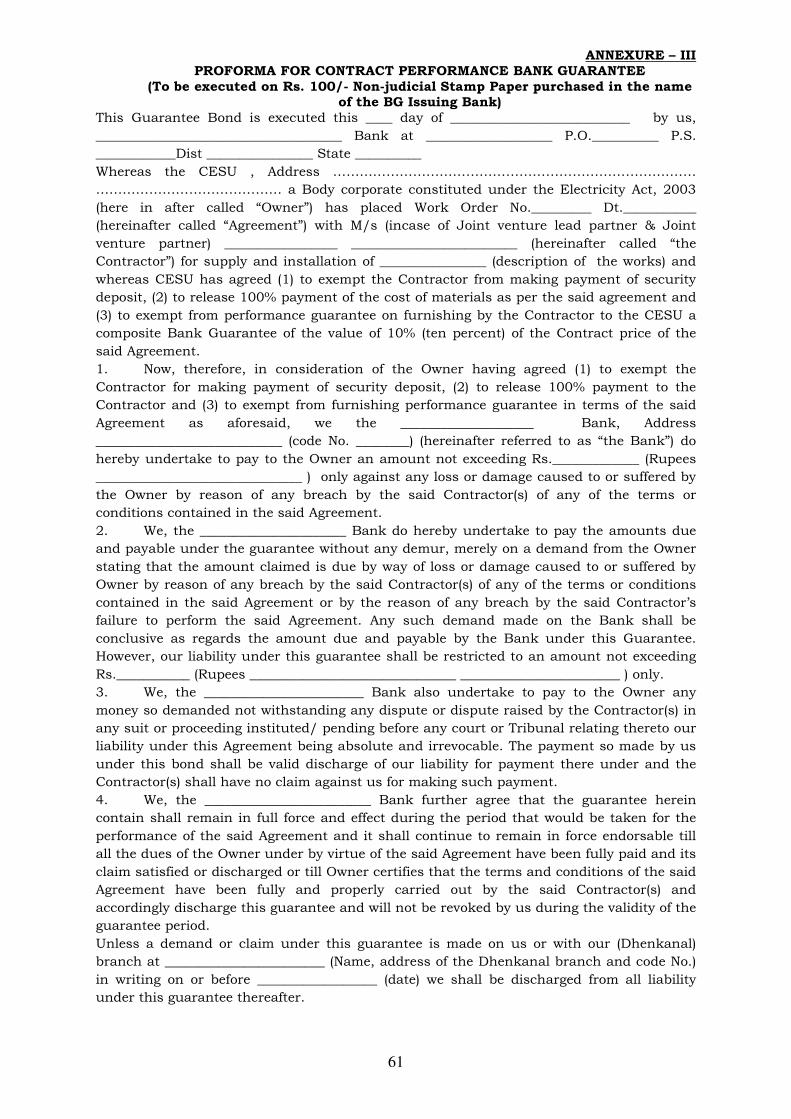
61
ANNEXURE – III PROFORMA FOR CONTRACT PERFORMANCE BANK GUARANTEE
(To be executed on Rs. 100/- Non-judicial Stamp Paper purchased in the name of the BG Issuing Bank)
This Guarantee Bond is executed this ____ day of ___________________________ by us,
_____________________________________ Bank at ___________________ P.O.__________ P.S.
____________Dist ________________ State __________
Whereas the CESU , Address ………………………………………………………………….……
…………………………………… a Body corporate constituted under the Electricity Act, 2003
(here in after called “Owner”) has placed Work Order No._________ Dt.___________
(hereinafter called “Agreement”) with M/s (incase of Joint venture lead partner & Joint
venture partner) _________________ _________________________ (hereinafter called “the
Contractor”) for supply and installation of ________________ (description of the works) and
whereas CESU has agreed (1) to exempt the Contractor from making payment of security
deposit, (2) to release 100% payment of the cost of materials as per the said agreement and
(3) to exempt from performance guarantee on furnishing by the Contractor to the CESU a
composite Bank Guarantee of the value of 10% (ten percent) of the Contract price of the
said Agreement.
1. Now, therefore, in consideration of the Owner having agreed (1) to exempt the
Contractor for making payment of security deposit, (2) to release 100% payment to the
Contractor and (3) to exempt from furnishing performance guarantee in terms of the said
Agreement as aforesaid, we the ____________________ Bank, Address
____________________________ (code No. ________) (hereinafter referred to as “the Bank”) do
hereby undertake to pay to the Owner an amount not exceeding Rs._____________ (Rupees
_______________________________ ) only against any loss or damage caused to or suffered by
the Owner by reason of any breach by the said Contractor(s) of any of the terms or
conditions contained in the said Agreement.
2. We, the ______________________ Bank do hereby undertake to pay the amounts due
and payable under the guarantee without any demur, merely on a demand from the Owner
stating that the amount claimed is due by way of loss or damage caused to or suffered by
Owner by reason of any breach by the said Contractor(s) of any of the terms or conditions
contained in the said Agreement or by the reason of any breach by the said Contractor’s
failure to perform the said Agreement. Any such demand made on the Bank shall be
conclusive as regards the amount due and payable by the Bank under this Guarantee.
However, our liability under this guarantee shall be restricted to an amount not exceeding
Rs.___________ (Rupees _______________________________ ________________________ ) only.
3. We, the ________________________ Bank also undertake to pay to the Owner any
money so demanded not withstanding any dispute or dispute raised by the Contractor(s) in
any suit or proceeding instituted/ pending before any court or Tribunal relating thereto our
liability under this Agreement being absolute and irrevocable. The payment so made by us
under this bond shall be valid discharge of our liability for payment there under and the
Contractor(s) shall have no claim against us for making such payment.
4. We, the _________________________ Bank further agree that the guarantee herein
contain shall remain in full force and effect during the period that would be taken for the
performance of the said Agreement and it shall continue to remain in force endorsable till
all the dues of the Owner under by virtue of the said Agreement have been fully paid and its
claim satisfied or discharged or till Owner certifies that the terms and conditions of the said
Agreement have been fully and properly carried out by the said Contractor(s) and
accordingly discharge this guarantee and will not be revoked by us during the validity of the
guarantee period.
Unless a demand or claim under this guarantee is made on us or with our (Dhenkanal)
branch at ________________________ (Name, address of the Dhenkanal branch and code No.)
in writing on or before __________________ (date) we shall be discharged from all liability
under this guarantee thereafter.
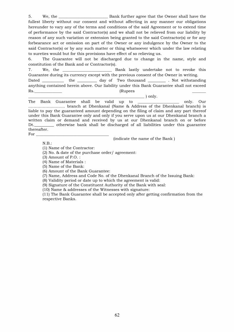
62
5. We, the _________________________ Bank further agree that the Owner shall have the
fullest liberty without our consent and without affecting in any manner our obligations
hereunder to vary any of the terms and conditions of the said Agreement or to extend time
of performance by the said Contractor(s) and we shall not be relieved from our liability by
reason of any such variation or extension being granted to the said Contractor(s) or for any
forbearance act or omission on part of the Owner or any indulgence by the Owner to the
said Contractor(s) or by any such matter or thing whatsoever which under the law relating
to sureties would but for this provisions have effect of so relieving us.
6. The Guarantee will not be discharged due to change in the name, style and
constitution of the Bank and or Contractor(s).
7. We, the _________________________ Bank lastly undertake not to revoke this
Guarantee during its currency except with the previous consent of the Owner in writing.
Dated ___________ the __________ day of Two thousand _________ . Not withstanding
anything contained herein above. Our liability under this Bank Guarantee shall not exceed
Rs.______________ (Rupees _______
___________________________________________________________ ) only.
The Bank Guarantee shall be valid up to _____________________ only. Our ………………………. branch at Dhenkanal (Name & Address of the Dhenkanal branch) is liable to pay the guaranteed amount depending on the filing of claim and any part thereof under this Bank Guarantee only and only if you serve upon us at our Dhenkanal branch a written claim or demand and received by us at our Dhenkanal branch on or before Dt.__________ otherwise bank shall be discharged of all liabilities under this guarantee thereafter. For _____________________________________
(indicate the name of the Bank ) N.B.: (1) Name of the Contractor: (2) No. & date of the purchase order/ agreement: (3) Amount of P.O. : (4) Name of Materials : (5) Name of the Bank: (6) Amount of the Bank Guarantee: (7) Name, Address and Code No. of the Dhenkanal Branch of the Issuing Bank: (8) Validity period or date up to which the agreement is valid: (9) Signature of the Constituent Authority of the Bank with seal: (10) Name & addresses of the Witnesses with signature: (11) The Bank Guarantee shall be accepted only after getting confirmation from the respective Banks.
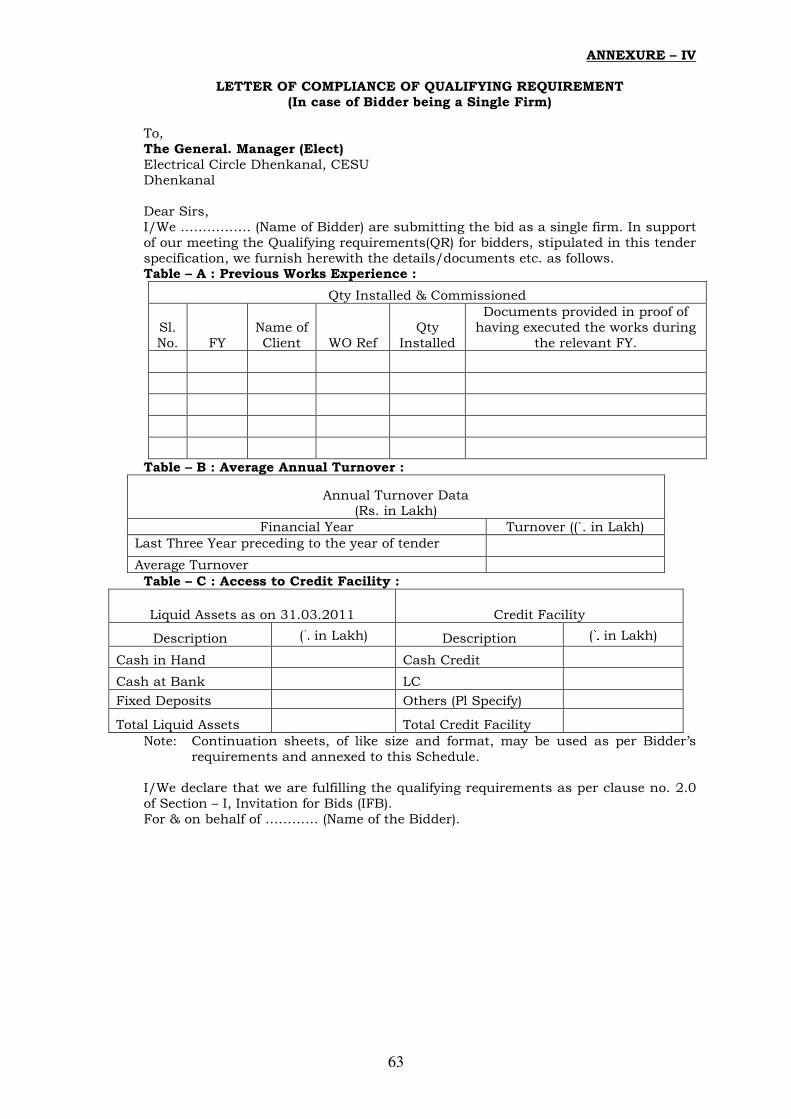
63
ANNEXURE – IV
LETTER OF COMPLIANCE OF QUALIFYING REQUIREMENT (In case of Bidder being a Single Firm)
To, The General. Manager (Elect) Electrical Circle Dhenkanal, CESU Dhenkanal Dear Sirs, I/We ……………. (Name of Bidder) are submitting the bid as a single firm. In support of our meeting the Qualifying requirements(QR) for bidders, stipulated in this tender specification, we furnish herewith the details/documents etc. as follows. Table – A : Previous Works Experience :
Qty Installed & Commissioned
Sl. No. FY
Name of Client WO Ref
Qty Installed
Documents provided in proof of having executed the works during
the relevant FY.
Table – B : Average Annual Turnover :
Annual Turnover Data (Rs. in Lakh)
Financial Year Turnover ((`. in Lakh)
Last Three Year preceding to the year of tender
Average Turnover
Table – C : Access to Credit Facility :
Liquid Assets as on 31.03.2011 Credit Facility
Description (`. in Lakh) Description (`. in Lakh)
Cash in Hand Cash Credit
Cash at Bank LC
Fixed Deposits Others (Pl Specify)
Total Liquid Assets Total Credit Facility
Note: Continuation sheets, of like size and format, may be used as per Bidder’s requirements and annexed to this Schedule.
I/We declare that we are fulfilling the qualifying requirements as per clause no. 2.0 of Section – I, Invitation for Bids (IFB). For & on behalf of ………… (Name of the Bidder).

64
ANNEXURE – V
DETAILS OF COMMERCIAL DEVIATIONS
Bidder’s Name & Address To, The General. Manager (Elect) Electrical Circle Dhenkanal ,CESU Dhenkanal Dear Sirs, Sub: Commercial Deviation for Construction of Name of the project. The following are the Commercial Deviations and variations from and exceptions to the specifications and documents for the subject Project. These deviations and variations are exhaustive. Except for these deviations, the entire work shall be performed as per your specifications and documents
Volume/Clause Brief
Description As specified in the Specification
Commercial deviation and variation to the specification
Date: (Signature) ………………….. Place: ( Printed Name) ………………. (Designation) ………………….. (Common Seal) ………………… Note: 1. Continuation sheets, of like size and format, may be used as per Bidder’s requirements and annexed to this Schedule. 2. This will be read out during opening of Part-I Bid.

65
ANNEXURE – VI
DETAILS TECHNICAL DEVIATIONS Bidder’s Name & Address To, The General. Manager (Elect) Electrical Circle Dhenkanal, CESU Dhenkanal Sub: Technical Deviation for Construction of ………………. Name of the Project. The following are the Technical Deviations and variations from and exceptions to the specifications and documents for the subject package. These deviations and variations are exhaustive. Except for these deviations, the entire work shall be performed as per your specifications and documents
Volume/Clause Ref./Page
No.
As specified in the Specification / Relevant
ISS
Technical deviation and variation to the specification
Date: (Signature) ………………….. Place: (Printed Name) ………………. (Designation) ………………….. (Common Seal) ………………… Note: 1. Continuation sheets, of like size and format, may be used as per Bidder’s requirements and annexed to this Schedule. 2. The deviations and variations, if any, shall be brought out separately for each of the equipment.
3. This will be read out during opening of Part – I bid.

66
ANNEXURE – VII ADDITIONAL INFORMATION
Bidder’s Name & Address To, The General Manager (Elect) Electrical Circle Dhenkanal, CESU Dhenkanal Dear Sirs, We have enclosed with our proposal the following additional information for the subject, package.
Sl. No Brief description of Information Ref.& Page No.
Date: (Signature) ………………….. Place: (Printed Name) ………………. (Designation) ………………….. (Common Seal) ………………… Note: Continuation sheets, of like size and format, may be used as per Bidder’s requirements and annexed to this Schedule.

67
ANNEXURE – VIII
WORK COMPLETION SCHEDULE
Bidder’s Name & Address To, The General Manager (Elect) Electrical Circle Dhenkanal, CESU Dhenkanal Dear Sirs, We hereby declare that the following Work Completion Schedule shall be followed by us for the purpose of subject package
Sl. No Description of Work Period in Months( from the date of LOA)
1 Completion of detailed engineering 2 Procurement of raw materials
3 Establishment of site office 4 Erection
(a) Commencement (b) Completion
5 Testing & Pre-commissioning
(a) Commencement (b) Completion
6 Commissioning
Date: (Signature) ………………….. Place: (Printed Name) ………………. (Designation) ………………….. (Common Seal) ………………..

68
ANNEXURE – IX CHECK LIST
Bidder’s Name & Address To, The General Manager (Elect) Electrical Circle Dhenkanal, CESU Dhenkanal
Sl. No.
Item Description Status of the Submission of data
Remarks
1 2 3 4
1. Bid Guarantee Yes /No If yes please give details No, amount, validity & date of issue.
2. Qualifying Data Yes /No
3. Commercial Deviation Yes /No
4. Technical Deviation Yes /No
5. Cost of withdrawn of deviations
Yes /No
6. Bid validity Yes /No If yes state here the period.
7. Period of completion Yes/No
If, yes please state here the period of completion.
8. Additional information offered by bidder
State here briefly
N.B.:- The contents of this schedule will be read out during opening of Part-I Bid. ……………………… Signature of Bidder Date & Seal:
1. The bid guarantee one original and one copy shall be furnished in two separate sealed envelope appropriately superscribed thereon.
2. All Schedules pertaining to prices (originals ) shall be furnished in a sealed envelope duly superscribed thereon. Similarly one set of copies of such schedules shall be given in a separate sealed envelope ( these are not to be opened during opening of Part –I ).
3. All other schedules, one set original and another copy shall be submitted in two separate sealed envelope (these are to be opened during Part –I bid opening )
Date: (Signature) ………………….. Place: (Printed Name) ………………. (Designation) ………………….. (Common Seal) ………………..