temposonics - mts sensors · the normal way is that the sensor and the hph housing are in one order...
TRANSCRIPT
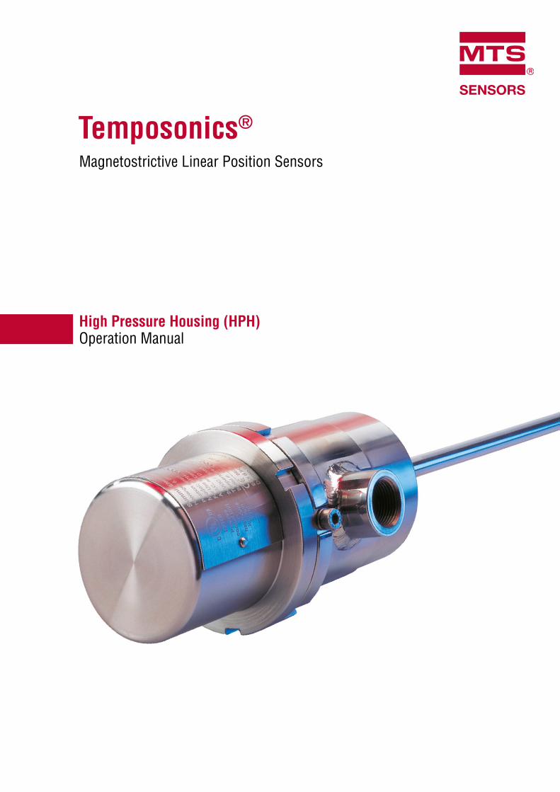
Temposonics®
Magnetostrictive Linear Position Sensors
High Pressure Housing (HPH)Operation Manual
High Pressure HousingOperation Manual
I 2 I
Safety InstructionsThe sensor must only be used according to the Ex certificates listed below. See product name plate for actual approvals.To reduce risk of ignition in hazardous atmospheres, disconnect theequipment from the supply circuit before opening. Keep assembleytightly closed when in operation. For use according to UL-listing, con-duit seals must be installed within 18" distance of the inclosure sensor must be connected to a Class 2 power supply. The housing parts must be kept as one unit.They are not interchangeable with parts from similar housings. Only tools applicable for use in explosive atmosphere must be used. When mounting the rod in “ZONE 0” it is necessary to prevent any leakage between “ZONE 0” and the surrounding environment. The sensor house must be connected to an equipotential bonding system or an earthing system.
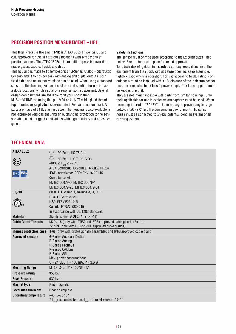
PRECISION POSITION MEASUREMENT – HPH
This High Pressure Housing (HPH) is ATEX/IECEx as well as UL and cUL approved for use in hazardous locations with Temposonics®
position sensors. The ATEX /IECEx, UL and cUL approvals cover flam-mable gases, vapors, liquids and dust.This housing is made to fit Temposonics® G-Series Analog + Start/Stop Sensors and R-Series sensors with analog and digital outputs. Both fixed cable and connector versions can be used. When using a standard sensor in this housing you get a cost efficient solution for use in haz-ardous locations which also allows easy sensor replacement. Several design combinations are available to fit your application: M18 or ¾"UNF mounting flange - M20 or ½" NPT cable gland thread - top mounted or single/dual side-mounted. See combination chart. All parts are made of 316L stainless steel. The housing is also available in non-approved versions ensuring an outstanding protection to the sen-sor when used in rigged applications with high humidity and agressive gases.
TECHNICAL DATA
ATEX/IECEx II 2G Ex db IIC T5 Gb
II 2D Ex tb IIIC T100°C Db-40°C ≤ Tamb ≤ +75°CATEX Certificate: ExVeritas 16 ATEX 0192XIECEx certificate: IECEx EXV 16.0014XCompliance withEN IEC 60079-0, EN IEC 60079-1EN IEC 60079-26, EN IEC 60079-31
UL/cUL Class 1, Division 1, Groups A, B, C, DUL/cUL-Certificates:USA: FTRV.E234045Canada: FTRV7.E234045In accordance with UL 1203 standard.
Material Stainless steel AISI 316L (1.4404)Cable Gland Threads M20×1.5 (only with ATEX and IECEx approved cable glands (Ex db))
½" NPT (only with UL and cUL approved cable glands)Ingress protection code IP68 (only with professionally assembled and IP68 approved cable gland)Approved sensors G-Series Analog + Digital
R-Series AnalogR-Series ProfibusR-Series CANbusR-Series SSIMax. power consumption: U = 24 VDC, I = 150 mA, P = 3.6 W
Mounting flange M18×1.5 or ¾" - 16UNF - 3A
Pressure rating 350 bar
Peak Pressure 530 bar
Magnet type Ring magnets
Level measurement Float on requestOperating temperature −40…+75 ºC 1
1/ Tamb+ is limited to max Tamb+ of used sensor −10 ºC
High Pressure HousingOperation Manual
I 3 I
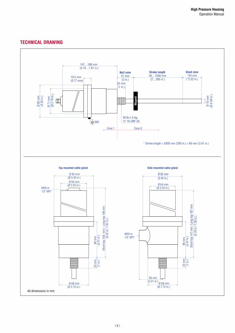
TECHNICAL DRAWING
All dimensions in mm
147…198 mm (5.79…7.81 in.)
19.5 mm (0.77 mm)
Ø 85
mm
(3.3
5 in
.)
Ø 71
mm
(Ø 2
.79
in.)
25 mm(1 in.)
Stroke length 50…7500 mm(2…295 in.)
Null zone51 mm(2 in.)
Ø 10
mm
(Ø 0
.39
in.)
Dead zone*64 mm
(*2.52 in.)
Zone 1 Zone 0
* Stroke length > 5000 mm (200 in.) = 66 mm (2.61 in.)
M5
Mag
net
M18×1,5-6g¾" 16 UNF-3A
Ø 64 mm(Ø 2.52 in.)
Ø 85 mm(Ø 3.45 in.)
Ø 69 mm(Ø 2.72 in.)
86 m
m(3
.41
in.)
25 m
m(1
in.)
Shor
t top
158
mm
/ L
ong
top
198
mm
(6.2
2 in
/ 7.
81 in
.)
Ø 64 mm(Ø 2.52 in.)
Ø 85 mm(3.45 in.)
Ø 69 mm(Ø 7.72 in.)
86 m
m(3
.41
in.)
25 m
m(1
in.)
Shor
t top
147
mm
/ Lo
ng to
p 18
7 m
m(5
.79
in /
7.36
in.)
56 mm(2.21 in.)
M20 or1/2" NPT
Top mounted cable gland Side mounted cable gland
M20 or1/2" NPT

High Pressure HousingOperation Manual
I 4 I
1.
Open the housing by turning the top counter clockwise. When opening after a sensor is installed, it is very im-portant to completely loosen the cable gland in order toprotect the cable against twisting and physical damage.The normal way is that the sensor and the HPH housing are in one order and then MTS Sensors supply the sen-sor mounted in the WPH housing. Go to step 7.
2.Remove rod or profile from the sensor.Separate the plastic tube from the sensor.
3. Cable gland
3.1 Insert the cable through the gland
3.2 Insert the connector through the top.
3.3Connect to the sensor and insert a bag of Desiccant in the top.
MOUNTING DISCRITPION

High Pressure HousingOperation Manual
I 5 I
3.4 Assemble the top and bottom turning clockwise.
3.5Tighten firmly until the top and bottom flanges come together.
3.6Tighten gable gland according to the manufacturer’s specifications.
4. Side mounted cable gland(s)
4.1 Enter the cable through the gland without tightening.
4.2For cable sizes larger than 7mm or very rigid cables, you may need to remove the outer insulation jacket from inside the cable gland to the connector

High Pressure HousingOperation Manual
I 6 I
4.3 Insert and fasten the sensor.
4.4 Make the connections.
4.5 Insert a bag of Desiccant in the top.
4.6
Assemble the top and bottom turning clockwise and tighten firmly until top and bottom flanges come together. (see fig. 11) Tighten the cable glands according to manufacturer‘s specifications.
5. Mount the grounding cable.
6. Tighten the lock screw with min. 1.5 Nm torque.

High Pressure HousingOperation Manual
I 7 I
ACCESSORIES
See document “551 444” for further accessories.
Position magnet Cable glands ATEX
Ø 32.8(Ø 1.29)
Ø 23.8(Ø 0.94)Ø 13.5
(Ø 0.53)
Ø 4.3(Ø 0.17)
7.9(0.31)
Ring magnet OD33Part no. 201 542-2
M20 × 1,5 Part no. CG-816679
M20 × 1,5Part no. CG-816609
½" NPT cable gland ATEX/CSA US, 180 °C; Part no. 403 042
Material: PA ferrite GF20Weight: ca. 14 gOperating temperature: −40…+100 °CSurface pressure: max. 40 N/mm2
Fastening torque for M4 screws:max. 1 Nm
Type no. ADE1F-4Material: stainless steelCable Ø: 4…8,5 mm
Type no. ADE1F-6Material: stainless steelCable Ø: 8.5…16 mm
Type no. A3LF/16 ½ NPTMaterial: nickel plated brassCable Ø: 4…8.4 mm
Spanner toolPart no. DIN 1018A AMF 80-90 mm
HPH rotation adapters
For M18, M30×1,5Part no. RTA-M18
For ¾" UNF; 1 1/16Part no. RTA-¾" UNF-2
For ¾" UNF; 1 ¼"Part no. 253 961
Cable connectors
Ø 17
.3(Ø
0.6
8)
~ 60.5(~ 2.38)
Female, straight, 6 pinPart no. 370 423
Female, straight, 6 pin with 10 m PUR cablePart no. MTS-A-370423-1000-530052
Housing: zinc nickel platedTermination: solderContact insert: silver platedCable clamp: PG9Cable Ø: 6…8 mm
UNITED STATESMTS Systems Corporation
Sensors DivisionAmericas & APAC Region
3001 Sheldon DriveCary, N.C. 27513Phone: +1 919 677-0100E-mail: [email protected]
GERMANYMTS Sensor Technologie
GmbH & Co. KGEMEA Region & India
Auf dem Schüffel 958513 LüdenscheidPhone: +49 2351 9587-0E-mail: [email protected]
ITALYBranch Offi ce
Phone: +39 030 988 3819E-mail: [email protected]
FRANCEBranch Offi ce
Phone: +33 1 58 4390-28E-mail: [email protected]
UK Branch Offi ce
Phone: +44 79 44 15 03 00E-mail: [email protected]
SCANDINAVIABranch Offi ce
Phone: + 46 70 29 91 281E-mail: [email protected]
CHINABranch Offi ce
Phone: +86 21 2415 1000 / 2415 1001E-mail: [email protected]
JAPANBranch Offi ce
Phone: +81 3 6416 1063E-mail: [email protected]
www.mtssensors.comMTS, Temposonics and Level Plus are registered trademarks of MTS Systems Corporation in the United States; MTS SENSORS and the MTS SENSORS logo are trademarks of MTS Systems Corporation within the United States. These trademarks may be protected in other countries. All other trademarks are the property of their respective owners. Copyright © 2019 MTS Systems Corporation. No license of any intellectual property rights is granted. MTS reserves the right to change the information within this document, change product designs, or withdraw products from availability for purchase without notice. Typographic and graphics errors or omissions are unintentional and subject to correction. Visit www.mtssensors.com for the latest product information.
Reg.-No. 003095-QM12
Document part number: 551751 Revision B (EN) 10/2019