temporary erosion and sediment control manual - tescm m … · temporary erosion and sediment...
TRANSCRIPT
Page 1 of 2
Publications Transmittal
Transmittal Number Date PT 14-021 April 2014 Publication Distribution To: Highway Runoff Manual Holders Publication Title (NEW) Publication Number Temporary Erosion and Sediment Control Manual – April 2014 M 3109.01 Originating Organization WSDOT Development Division, Design Office – HQ Highway Runoff Program
About the new Temporary Erosion and Sediment Control Manual (TESCM): The information in the TESCM is not new; it used to be located in Chapter 6 of the Highway Runoff Manual (HRM). It was determined that it would be better as a separate manual because it has a different audience than the rest of the HRM. Also, the HRM is updated based on the Municipal Stormwater permit and the TESCM material needs to be updated based on the Construction Stormwater permitting cycle (different than the Municipal permitting cycle.)
If you have comments or questions about the Temporary Erosion and Sediment Control Manual, please contact:
TESCM General Guidance and Support Elsa Pond 360-705-6654 [email protected]
To get the latest information on individual WSDOT publications: Sign up for email updates at: www.wsdot.wa.gov/publications/manuals/
HQ Design Office Signature /s/ Elsa Pond
Phone Number 360-570-6654

Page 2 of 2

Temporary Erosion and Sediment Control Manual
M 3109.01
April 2014
Engineering and Regional Operations Development Division, Design Office

Americans with Disabilities Act (ADA) Information
This material can be provided in an alternative format by emailing the WSDOT Diversity/ ADA Affairs team at [email protected] or by calling 360-705-7097 or toll free: 855-362-4ADA (4232). Persons who are deaf or hard of hearing may contact the Washington Relay Service at 7-1-1. Title VI Notice to Public
It is Washington State Department of Transportation (WSDOT) policy to ensure no person shall, on the grounds of race, color, national origin, or sex, as provided by Title VI of the Civil Rights Act of 1964, be excluded from participation in, be denied the benefits of, or be otherwise discriminated against under any of its federally funded programs and activities. Any person who believes his/her Title VI protection has been violated may file a complaint with WSDOT’s Office of Equal Opportunity (OEO). For Title VI complaint forms and advice, please contact OEO’s Title VI Coordinator at 360-705-7082 or 509-324-6018.
To get the latest information on individual WSDOT publications, sign up for email updates at: www.wsdot.wa.gov/publications/manuals
WSDOT Temporary Erosion and Sediment Control Manual M 3109.01 Page iii April 2014
Foreword
The Temporary Erosion and Sediment Control Manual (TESCM) replaces Chapter 6 and Appendix 6A of the Washington State Department of Transportation (WSDOT) Highway Runoff Manual. It outlines WSDOT’s policies for meeting the National Pollutant Discharge Elimination System (NPDES) Construction Stormwater General Permit requirements and the requirements in Volume II of the stormwater management manuals published by the Washington State Department of Ecology.
The TESCM is intended for use during the design, permitting, and construction phases of transportation construction projects. It covers:
TESC plan design and implementation
TESC BMP application and installation
SPCC plans
Discharge sampling and reporting
Site management and documentation
Compliance-related issues
For further information, contact the Erosion Control section of WSDOT’s Environmental Services Office, Stormwater and Watersheds program: www.wsdot.wa.gov/environment/waterquality/erosioncontrol.htm
/s/ Pasco Bakotich III
Pasco Bakotich III, P.E. Director & State Design Engineer, Development Division

Foreword
Page iv WSDOT Temporary Erosion and Sediment Control Manual M 3109.01 April 2014

WSDOT Temporary Erosion and Sediment Control Manual M 3109.01 Page v April 2014
Contents Chapter 1 General Information .................................................................................................................. 1
1-1 Introduction .................................................................................................................................. 1 1-1.1 Construction Stormwater Permitting .............................................................................. 3
Chapter 2 TESC Plan Design ....................................................................................................................... 5 2-1 Temporary Erosion and Sediment Control (TESC) Plan Design .................................................... 5
2-1.1 TESC Data Collection and Risk Analysis ........................................................................... 6 2-1.1.1 Soil Type .......................................................................................................... 7 2-1.1.2 Climate and Precipitation Patterns ................................................................. 8 2-1.1.3 Land Cover and Existing Vegetation ................................................................ 8 2-1.1.4 Topography ..................................................................................................... 9 2-1.1.5 Drainage and Adjacent Areas ........................................................................ 10 2-1.1.6 Groundwater, Seeps, and Seasonal Springs .................................................. 10 2-1.1.7 Sensitive Areas, Existing Contamination, or Impaired Receiving Waters ..... 11 2-1.1.8 Utilities and Existing Encumbrances ............................................................. 11 2-1.1.9 Timing, Duration, and Work Sequencing ...................................................... 12
2-1.2 BMP Selection and TESC Planning Elements ................................................................. 12 2-1.2.1 TESC Planning Elements ................................................................................ 13
2-1.3 Construction Schedule and BMP Implementation ........................................................ 25 2-1.4 Scoping and Budgeting .................................................................................................. 27
2-1.4.1 Cost-Based Estimate ...................................................................................... 27 2-1.4.2 Bid-Based Estimate ........................................................................................ 27 2-1.4.3 Construction Contract Information System .................................................. 28
2-1.5 Contract Enforcement ................................................................................................... 28 Chapter 3 SPCC Plans ............................................................................................................................... 29
3-1 Spill Prevention Control and Countermeasures Plan ................................................................. 29 Chapter 4 Site Management, Reporting, and Compliance ...................................................................... 31
4-1 Site Management and Discharge Sampling ................................................................................ 31 4-1.1 Certified Erosion and Sediment Control Lead (CESCL) .................................................. 31 4-1.2 Preparation for Discharge Sampling and Reporting ...................................................... 32 4-1.3 Discharge Sampling Requirements for Turbidity and pH .............................................. 37 4-1.4 Site Inspections and TESC Plan Adaptive Management ................................................ 42 4-1.5 Site Log Book ................................................................................................................. 43 4-1.6 Miscellaneous Reporting and Compliance-Related Issues ............................................ 43
4-1.6.1 Permit Violations ........................................................................................... 43 4-1.6.2 Environmental Compliance Assurance Procedure (ECAP) ............................ 44 4-1.6.3 Discharge Sampling Not Conducted .............................................................. 44 4-1.6.4 Temporarily Stabilized Inactive Sites and Projects in Winter Shutdown ...... 45

Contents
Page vi WSDOT Temporary Erosion and Sediment Control Manual M 3109.01 April 2014
4-1.6.5 Notice of Termination ................................................................................... 45 4-1.6.6 In-Water Work ............................................................................................... 45 4-1.6.7 Impaired Receiving Waters ........................................................................... 46 4-1.6.8 Construction Projects Not Covered by a Construction Stormwater General
Permit (CSWGP)............................................................................................. 46 4-1.6.9 Discharges to a Sanitary Sewer ..................................................................... 47 4-1.6.10 Other Applicable Regulations ........................................................................ 47
Chapter 5 TESC Best Management Practices ........................................................................................... 49 5-1 Introduction ................................................................................................................................ 49
5-1.1 TESC BMPs ..................................................................................................................... 49 5-1.1.1 BRUSH BARRIERS ........................................................................................... 50 5-1.1.2 BUFFER ZONES............................................................................................... 51 5-1.1.3 CERTIFIED EROSION AND SEDIMENT CONTROL LEAD (CESCL) ..................... 51 5-1.1.4 CHECK DAMS ................................................................................................. 52 5-1.1.5 COMPOST SOCKS ........................................................................................... 53 5-1.1.6 CONCRETE CUTTING AND GRINDING POLLUTION PREVENTION .................. 54 5-1.1.7 CONCRETE HANDLING ................................................................................... 55 5-1.1.8 CONCRETE WASHOUT AREAS ........................................................................ 56 5-1.1.9 CONSTRUCTION ROAD AND PARKING AREA STABILIZATION ........................ 57 5-1.1.10 CONSTRUCTION STORMWATER CHEMICAL TREATMENT ............................. 58 5-1.1.11 CONSTRUCTION STORMWATER FILTRATION ................................................ 59 5-1.1.12 CONVEYANCE CHANNEL STABILIZATION ....................................................... 60 5-1.1.13 DUST CONTROL ............................................................................................. 64 5-1.1.14 EROSION CONTROL BLANKETS ...................................................................... 65 5-1.1.15 FILTER BERMS ................................................................................................ 66 5-1.1.16 GRADIENT TERRACES ..................................................................................... 66 5-1.1.17 HIGH-pH STORMWATER NEUTRALIZATION .................................................. 68 5-1.1.18 HIGH-VISIBILITY FENCING .............................................................................. 70 5-1.1.19 HYDRAULICALLY-APPLIED EROSION CONTROL PRODUCTS (HECPS) ............. 70 5-1.1.20 INTERCEPTOR DIKES AND SWALES ................................................................ 71 5-1.1.21 LEVEL SPREADERS .......................................................................................... 74 5-1.1.22 MATERIALS HANDLING, STORAGE, AND CONTAINMENT ............................. 75 5-1.1.23 MATERIALS ON HAND ................................................................................... 76 5-1.1.24 MULCHING .................................................................................................... 77 5-1.1.25 OUTLET PROTECTION .................................................................................... 79 5-1.1.26 PIPE SLOPE DRAINS ....................................................................................... 79 5-1.1.27 PLASTIC COVERING ........................................................................................ 81 5-1.1.28 POND SKIMMERS .......................................................................................... 82 5-1.1.29 PRESERVING NATURAL VEGETATION ............................................................ 82 5-1.1.30 SCHEDULING AND COORDINATING WORK ACTIVITY .................................... 83

Contents
WSDOT Temporary Erosion and Sediment Control Manual M 3109.01 Page vii April 2014
5-1.1.31 SEDIMENT TRAPS .......................................................................................... 84 5-1.1.32 SEDIMENTATION BAGS ................................................................................. 86 5-1.1.33 SILT FENCE ..................................................................................................... 87 5-1.1.34 SODDING ....................................................................................................... 88 5-1.1.35 STABILIZED CONSTRUCTION ENTRANCES ..................................................... 88 5-1.1.36 STORM DRAIN INLET PROTECTION ............................................................... 89 5-1.1.37 STRAW WATTLES ........................................................................................... 90 5-1.1.38 SUBSURFACE DRAINS, FRENCH DRAINS, AND SUMP SYSTEMS .................... 91 5-1.1.39 SURFACE ROUGHENING ................................................................................ 91 5-1.1.40 TACKIFIERS AND POLYACRYLAMIDE .............................................................. 92 5-1.1.41 TEMPORARY AND PERMANENT SEEDING ..................................................... 93 5-1.1.42 TEMPORARY CURBS OR WATER BARS ........................................................... 94 5-1.1.43 TEMPORARY OR MOBILE CONTAINMENT ..................................................... 95 5-1.1.44 TEMPORARY SEDIMENT PONDS .................................................................... 95 5-1.1.45 TIRE WASH ................................................................................................... 101 5-1.1.46 TOPSOILING ................................................................................................. 102 5-1.1.47 VEGETATED STRIPS ...................................................................................... 102 5-1.1.48 VEGETATIVE DISPERSION AND INFILTRATION............................................. 103 5-1.1.49 WATER PUMPS ............................................................................................ 104
Figures Figure 4-1 Common discharge sample locations. ................................................................................... 36 Figure 5-1 Sediment Trap Cross Section (from Ecology’s SWMMWW, 2012) ........................................ 86 Figure 5-2 Sediment Trap Outlet (from Ecology’s SWMMWW, 2012) ................................................... 86 Figure 5-3 Temporary sediment pond details. ..................................................................................... 100
Tables Table 5-1 Flexible versus rigid lined conveyances. ................................................................................ 63 Table 5-2 Maximum permissible shear stresses for flexible liners. ....................................................... 63 Table 5-3 Dike and swale design criteria. .............................................................................................. 73 Table 5-4 Mulch standard specifications and guidelines....................................................................... 78 Table 5-5 Vegetated strips. .................................................................................................................. 103

Contents
Page viii WSDOT Temporary Erosion and Sediment Control Manual M 3109.01 April 2014
WSDOT Temporary Erosion and Sediment Control Manual M 3109.01 Page 1 April 2014
Chapter 1 General Information
1-1 Introduction The Temporary Erosion and Sediment Control Manual (TESCM) provides the Washington State Department of Transportation (WSDOT) policy for complying with the stormwater pollution prevention planning (SWPPP), discharge sampling and reporting requirements in the National Pollutant Discharge Elimination System (NPDES) Construction Stormwater General Permit (CSWGP), issued by the Washington State Department of Ecology (Ecology). In combination, the TESCM and WSDOT’s Highway Runoff Manual (HRM) are deemed equivalent to Ecology’s stormwater management manuals.
Erosion is a natural process that can be accelerated by human activity. Construction activities such as removing vegetation, disturbing soil, and redirecting drainage can increase the natural rates of erosion. Erosion is the removal of soil from its original location by forces such as wind, water, or gravity. The erosion process by water is as follows:
Raindrop or Splash Erosion: Soil particles are displaced by raindrop impact.
Sheet Erosion: Uniform layer of shallow flow that moves loose soil particles.
Rill Erosion: Concentrated flows create small eroded channels, and erosive energy begins to increase.
Gully Erosion: High-volume, high-velocity, concentrated flows displace large amounts of soil quickly, creating large eroded channels.
Channel or Streambank Erosion: Shear stress along conveyance walls removes soil.
Mass Wasting or Slumping: Soil structural failure is caused by factors such as saturation, vegetation removal, and soil type.
Sedimentation is the gravity-induced settling or the deposition of suspended soil particles. Sediment control best management practices (BMPs) are used to minimize off-site sedimentation, to minimize the amount of sediment leaving the project boundaries. Sediment control BMPs are often referred to as treatment BMPs because they work to clean dirty water, typically by slowing down, trapping, or filtering flows. Sediment control BMPs are required to be in place so all runoff from construction areas will receive treatment prior to a discharge. Sediment control BMPs can be used within a site to treat flows, but they are required to be used at discharge points so untreated water does not discharge from project boundaries (sometimes called perimeter sediment control). Sediment control BMPs need to be maintained regularly because they fill with sediment or become clogged. Most sediment control BMPs do not prevent erosion; therefore, it is important to install erosion control BMPs as soon as work allows.

General Information Chapter 1
Page 2 WSDOT Temporary Erosion and Sediment Control Manual M 3109.01 April 2014
Erosion control BMPs minimize erosion by covering and stabilizing soil or preventing concentrated flows from developing (dissipating erosive energy). Erosion control BMPs are often referred to as source control BMPs because they work to manage the sources of pollution, such as areas of exposed soil.
Erosion cannot always be prevented in actively worked construction areas, which is why sediment control BMPs must always be used at discharge points. However, when an area is not being actively worked, it must be temporarily stabilized in accordance with the soil-covering timelines outlined in the CSWGP and the Standard Specifications for Road, Bridge, and Municipal Construction (8-01.3(1)). Erosion and sediment control BMPs are outlined in Chapter 5.
The CSWGP requires stormwater pollution prevention planning (SWPPP), BMP adaptive management, weekly site inspections, discharge sampling, and reporting to ensure erosion-related risks are being managed appropriately. Erosion and off-site sedimentation can have numerous impacts, such as:
Degradation of habitat, aesthetic, and recreational uses of surface waters.
Water quality impacts such as nutrient loading and eutrophication.
Increased stormwater system maintenance and operational costs.
Loss of nutrient-rich topsoil.
Construction site stormwater runoff is subject to federal, state, and local regulatory requirements. These impacts can increase project costs through legal fines and repair of site damage that causes delays to project delivery. As defined in Chapter 90.48 Revised Code of Washington (RCW), Ecology has been delegated the authority to administer the NPDES permit program in Washington State. In addition, many local governments within the state have established their own additional permits. Permittees should check with local jurisdictions about additional requirements related to construction stormwater.
WSDOT uses temporary erosion and sediment control (TESC) plans and spill prevention control and countermeasures (SPCC) plans to identify and minimize erosion and spill-related risks during construction. Together, the TESC and SPCC plans are designed to satisfy the SWPPP requirements as outlined in the CSWGP.
A TESC plan must be prepared if the construction project is covered by a CSWGP, or if one is required by Ecology or a local permitting authority. Projects that disturb soil, but are not covered by a CSWGP, must develop an abbreviated TESC plan. An abbreviated TESC plan must include all TESC planning elements that pertain to the project. It must also outline the BMPs that will be used to control sources of pollution and maintain compliance with the water quality standards for surface waters in Washington Administrative Code (WAC) 173-201A.

Chapter 1 General Information
WSDOT Temporary Erosion and Sediment Control Manual M 3109.01 Page 3 April 2014
All WSDOT staff who design or implement TESC plans should attend the WSDOT Construction Site Erosion and Sediment Control course every three years to ensure they understand the most current permit requirements. The course covers WSDOT procedures related to TESC planning, including designing a TESC plan, weekly site inspections, adaptive management, discharge sampling, and reporting requirements.
Section 4-1.1 has information about how this course may be used in WSDOT’s internal Certified Erosion and Sediment Control Lead (CESCL) training program. Check the Learning Management System (LMS) for class availability or contact the Headquarters (HQ) Erosion Control program.
SPCC plans are prepared by the contractor as required in Standard Specification 1-07.15(1). Additional information about SPCC plans can be found in Section 3-1 of this manual. SPCC plan preparation instructions for contractors can be found on the HQ Hazardous Materials Program website: www.wsdot.wa.gov/environment/hazmat/spillprevention.htm
1-1.1 Construction Stormwater Permitting
All projects that disturb 1 acre or more of soil and have the potential to discharge to surface waters of the state are required to apply for coverage under the NPDES Construction Stormwater General Permit (CSWGP). In addition:
Projects smaller than 1 acre, but part of a larger common plan of development or sale that will ultimately disturb 1 acre or more and discharge stormwater to surface waters of the state, must also apply for coverage. The disturbed area of the entire common plan must be used in determining permit requirements.
Projects that are deemed by Ecology to be a significant contributor of pollutants or that Ecology reasonably expects to cause a violation of any water quality standard, must also apply for coverage.
Ecology has been delegated the authority under the federal Clean Water Act (CWA) to issue the CSWGP in Washington State. Projects within an Indian reservation1 are not covered by the Ecology-issued CSWGP; they must seek coverage under the federal NPDES Construction General Permit (CGP) issued by the U.S. Environmental Protection Agency (EPA). The details of the federal CGP are not discussed in this manual. Use the EPA electronic Notice of Intent (eNOI) system to apply for the federal CGP if needed.
Projects seeking coverage under the Ecology CSWGP must apply for coverage by submitting a Notice of Intent (NOI); Ecology prefers that its electronic (eNOI) system be used. The project name submitted in the NOI shall be 40 characters or less. If WSDOT will be the permittee, include “WA DOT” as a prefix to the project name on the NOI so WSDOT’s reporting responsibilities can be tracked in Ecology’s electronic permitting and reporting systems. Refer to the Environmental Manual (EM) for more information.
1 There is an exception for the Puyallup reservation, which is defined in Special Condition S1.E.3 of the CSWGP.

General Information Chapter 1
Page 4 WSDOT Temporary Erosion and Sediment Control Manual M 3109.01 April 2014
The application requirements and timelines outlined in Special Condition S2 of the CSWGP must be followed. It can take up to 60 calendar days to receive permit coverage once the NOI is submitted. Internal guidance is available on the Erosion Control intranet page for the following aspects of the NOI process:
All potential temporary outfall locations to receiving surface waters during construction
The Request for Chemical Treatment form2
The Proposed New Discharge to Impaired Water Body form3
When NOIs are submitted to a permitting authority, send a courtesy copy of the NOI to the WSDOT Erosion Control program so Headquarters is aware of upcoming projects that will have CSWGPs.
2 Required to be submitted to Ecology prior to a discharge if the project plans to use chemical treatment on polluted water, such as chitosan enhanced sand filtration (CESF) or electrocoagulation (EC). Find this form on Ecology’s website: http://www.ecy.wa.gov/programs/wq/stormwater/construction/permit.html 3 Will be sent to permittee by Ecology if the NOI includes temporary outfalls into impaired receiving waters. This form can also be found on Ecology’s website (see above).

WSDOT Temporary Erosion and Sediment Control Manual M 3109.01 Page 5 April 2014
Chapter 2 TESC Plan Design
2-1 Temporary Erosion and Sediment Control (TESC) Plan Design A TESC plan consists of a narrative section and contract plan sheets.
The TESC narrative provides specific information about site conditions, analyzes risks, outlines management strategies and contingency plans, and should reference relevant Standard Specifications, Special Provisions, and Standard Plans.
The TESC contract plan sheets are used to show important locational and directional information (such as BMP and discharge sample locations).
This section provides guidelines for creating a TESC plan narrative. A TESC plan narrative template and checklist are available on the Erosion Control program’s SharePoint site.
A TESC plan must provide site-specific information about the erosion-related risks on a project and a strategy for managing those risks on day one of construction. Once construction begins, keep the TESC plan on-site and continually adapt it as needed based on site conditions, changing risks, site inspections, and discharge sample values. Update the on-site TESC plan to represent site conditions and BMP adaptive management, such as BMPs added, maintained, or removed. Write updates into the narrative or draw them onto the contract plan sheets (see Section 4-1.4). For large projects that will be under construction for multiple seasons, you are encouraged to create phased TESC plans (or multiple TESC plans for projects that require unique erosion control measures for each phase).
TESC plan narratives must include:
√ A project description and overview section that includes information about the nature and purpose of the projects, total area, disturbed acreage, and location.
√ Information about existing site conditions and factors that affect erodibility, such as topography, precipitation, drainage, soil type (see Section 2-1.1).
√ A management strategy for potential problem or hard-to-manage areas.
√ A risk analysis for the 13 TESC planning elements (see Section 2-1.2.1), including a list of the potential BMPs that may be used to address those risks. Include a list of applicable Standard Specifications, General Special Provisions (GSPs), and Special Provisions as needed.
√ Relevant information that was used to make the pollution-prevention decisions for the project, including sizing calculations for ponds or other designed structures.
√ Phasing or sequencing plans that may impact risks, and a general BMP implementation schedule (often confirmed during the preconstruction meeting).
TESC Plan Design Chapter 2
Page 6 WSDOT Temporary Erosion and Sediment Control Manual M 3109.01 April 2014
√ Contingency plans if BMP performance goals are not achieved (e.g., how the project will manage high-pH stormwater runoff if it is generated).
√ On-site CESCL contact information (may need to be added during construction).
TESC contract plan sheets must include:
√ Direction of north, property lines, existing structures, roads, and impervious surfaces.
√ Cut and fill slopes indicating the top and bottom of slope catch lines.
√ Approximate slopes, contours, and direction of stormwater flow before and after major grading activities.
√ Areas of soil disturbance and areas that will not be disturbed.
√ Locations of BMPs.
√ Off-site material or borrow areas, stockpiles, waste storage, and equipment storage areas that are covered under the WSDOT CSWGP permit.
√ Locations of all surface water bodies, including wetlands and protected areas.
√ Temporary outfall locations to surface waters of the state (identified in the NOI).
√ Discharge sample location(s) are generally not known until construction begins. Once construction begins, these locations must be added to the on-site contract plan sheets and updated as needed.
√ Areas where final stabilization (construction complete and soils stabilized with permanent BMPs) has been achieved.
Refer to the Plans Preparation Manual for more information on contract plan sheet preparation.
2-1.1 TESC Data Collection and Risk Analysis
All TESC plans are required to include the information outlined in Section 2-1. However, the time and effort put into a TESC plan should be proportionate to the site-specific risks of the given project. High- to moderate-risk construction projects require more detailed risk analysis, thoughtful BMP implementation strategies, and contingency planning.
Most high- to moderate-risk projects involve more than 1 acre of soil disturbance, discharge to surface waters within 300 feet of the project, and meet at least three of the following four characteristics:
More than 50% of the site consists of soils in Hydrologic Groups C and D as defined by the Natural Resource Conservation Service (NRCS) soil surveys.
They involve wet-season (October through April west of the Cascades or October through June east of the Cascades) work or last more than one year.

Chapter 2 TESC Plan Design
WSDOT Temporary Erosion and Sediment Control Manual M 3109.01 Page 7 April 2014
Their cut/fill slopes exceed more than 50 feet in length.
They have active seeps or shallow groundwater.
To have a successful TESC plan, identify the risks and outline a strategy to minimize and manage risks with effective combinations of BMPs. Think critically about the project, the scheduled work, and the factors that affect risk, in order to identify potential risks that should be included in the plan. When gathering information for a TESC plan, consider the following resources:
The Erosion Control program SharePoint TESC Planning folder
The Environmental layers in the GIS Workbench, Soil Surveys, and design storm modeling tools like MGSFlood or StormShed
Hydraulic Analysis and Geotechnical Analysis reports
Site visits (during different seasons if feasible)
Regional maintenance staff (consult about existing drainage patterns)
Begin every TESC planning process by collecting information about the factors that affect the erosion-related risks on a project (outlined below). Incorporate the information collected during this process into the TESC plan narrative (in the project overview section or in the TESC planning element risk analysis section) and show on the contract plan sheets where feasible. As you collect data, think critically and proactively about what the data means for site management during construction. The following categories are the most common factors that affect erosion-related risks on construction projects.
2-1.1.1 Soil Type
The proportion and arrangement of sand, silt, clay, and organic matter determines soil texture. Soil texture greatly affects the vulnerability to erosion, the cohesiveness of the soil, how quickly the suspended particles will settle out due to gravity, and the rate at which infiltration will occur.
Knowing the characteristics (e.g., texture, particle size, organic matter, and permeability) of on-site soil will help you select appropriate BMPs. For example, you can use rock check dams in eastern Washington to provide both erosion and sediment control; they are fairly effective because the soil tends to be sandy. Check dams work to slow flow, which minimizes the erosive energy and allows sand to settle out in the slow-moving water. However, western Washington tends to have more fine silt and clay soils. While rock check dams can still be used to slow flow, they are not very effective at providing sediment control (treatment) when soil particles are small and stay suspended longer. Check dams that don’t allow water to flow freely through, such as a geotextile-encased dam or a compost sock, work much better for sediment control in western Washington.
TESC Plan Design Chapter 2
Page 8 WSDOT Temporary Erosion and Sediment Control Manual M 3109.01 April 2014
Obtain information on soil characteristics for any given project from several sources, including geotechnical reports, soil boring logs, NRCS soil surveys, and on-site evaluations with soil ribbon or jar testing. Refer to Chapter 4 (Hydrologic Analysis) of the HRM, which provides guidelines for determining soil-related risks. Additional WSDOT resources include Region Environmental, Maintenance, and Landscape offices, Region Materials Engineers, and the HQ Erosion Control program.
2-1.1.2 Climate and Precipitation Patterns
The frequency, intensity, and duration of rainfall events greatly affect the potential for erosion. The patterns of rainfall events influence soil saturation. Once soil is saturated, more water will flow over the top of the soil rather than infiltrating; this increases the potential for erosion or a discharge from the project boundaries. The kinetic energy of raindrops will loosen and displace sediment. High-intensity rain events can create concentrated flows or flashy runoff volumes, which need to be managed to minimize damage to slopes, conveyances, drainage features, and downstream properties.
Knowing the probability of these precipitation patterns at any given location will help you select and size appropriate BMPs. Climate information is also vital to the timing and phasing of construction activity to minimize risks.
The HRM (Appendix 4A) and the Hydraulics Manual (Chapter 2, Appendix 2-3) contain isopluvial maps for mean annual precipitation, design storm events, and mean annual runoff that can be used to get a general idea about rainfall patterns in any given part of the state. The GIS Workbench is also a great resource for information on climate and precipitation patterns.
The Western Regional Climate Center (WRCC) website has statistical information on precipitation, temperature, and several other climatic measurements for over 200 sampling stations throughout the state. The WRCC website includes interactive probability-graphing capabilities ( www.wrcc.dri.edu/summary/climsmwa.html).
2-1.1.3 Land Cover and Existing Vegetation
The type of land cover greatly influences the volume of runoff, peak discharge rates, and the vulnerability to erosion. Construction areas that have been cleared and graded create large amounts of runoff because the absorbent soil horizons (organic layer and topsoil) are often removed. In many cases, what remains is highly compacted subsoil that provides minimal infiltration capacity and generates a lot of runoff. Removing vegetation also means there will be no tree canopy to intercept raindrop impact or organic material on the soil surface to slow overland flows. Therefore, the volume and velocity of overland flows in graded areas can increase quickly.

Chapter 2 TESC Plan Design
WSDOT Temporary Erosion and Sediment Control Manual M 3109.01 Page 9 April 2014
Vegetation is the most effective erosion and sediment control BMP, and existing site vegetation is free. It protects soil from raindrop impact and increases infiltration rates, and root systems hold the soil together. Vegetation also slows and filters sheet flow. To minimize erosion-related risks:
Preserve existing vegetation as much as possible and phase work to limit the amount of vegetation that is removed at one time.
Set clearing limits to minimize vegetation removal, and label any areas of existing vegetation that can be protected on the TESC plan sheets.
Consider areas where permanent vegetation could be re-established as early as possible during construction.
2-1.1.4 Topography
The three-dimensional surface of the terrain (existing, temporary grade, and permanent grade) will greatly influence the potential for erosion. The potential for erosion increases exponentially with increasing slope length and gradient; as runoff converges and moves faster down a long, steep slope, kinetic energy increases and the potential for erosion increases. Rill or gully erosion can develop quickly and displace a large amount of sediment.
During construction, before permanent controls are in place, use temporary BMPs to prevent unmanaged concentrated erosive flows from developing into rills and gullies. Choose BMPs that dissipate flow energy, such as compost socks, wattles, check dams, berms, or rock spillways, which work well in areas at risk of having concentrated flows develop, such as slopes, conveyances, or areas where sheet flows converge and run off the edge of an impervious surface.
Cut and fill slopes are particularly vulnerable to erosion. Temporary BMPs used to cover slope soils, like blankets and hydromulches, protect against raindrop erosion but will not protect a slope from concentrated flows. Use top-of-slope BMPs to prevent concentrated flows from reaching cut and fill areas or exposed slopes. In addition, use BMPs like wattles and compost socks to break up the continuous length of a slope and dissipate flow energy.
Evaluate the size, slope length, gradient, and stability (soil type or vegetative cover) of planned slopes in the project work area to assess potential risks during construction. Whenever slopes are created with Hydrologic Group C or D soils, there is an increased risk of large slope failures, especially when silt content exceeds 30%. All soil types, regardless of composition, are vulnerable to rapid rill and gully erosion when concentrated flows are not diverted away from slopes.
In addition, groundwater seepage or ephemeral streams increase the potential for slope failures with all soil types. If geotechnical analysis was done for a project, the report may help you identify areas where these sources of water may occur. Performing site visits in the rainy season during the planning phases of a project can also help you identify such risks.
TESC Plan Design Chapter 2
Page 10 WSDOT Temporary Erosion and Sediment Control Manual M 3109.01 April 2014
Identify areas that can be used to reduce the risk of erosion and turbid water discharges. Use closed natural depressions, upland areas, flat areas, and vegetated areas to disperse or infiltrate runoff, which will greatly reduce the risk of turbid water discharges. Label dispersion and infiltration areas on the TESC plan sheets, as these areas are considered BMPs.
2-1.1.5 Drainage and Adjacent Areas
Off-site water that runs onto a project (run-on) can cause tremendous damage because it may generate stormwater volumes that far exceed the design capacity of the on-site stormwater conveyance and treatment BMPs such as ponds. Some of WSDOT’s largest erosion-related cost overruns and fines in past years were related to unidentified off-site sources of water entering construction sites.
Identify potential sources of off-site water run-on during the TESC planning phase. Off-site water run-on sources may include: natural sheet flow from neighboring facilities; overland flow from upland areas outside the project boundary; permitted or illicit stormwater discharges from neighboring buildings and parking lots; groundwater seeps; water from neighboring construction projects; or unmapped seasonal drainages.
Whenever possible, divert run-on around the construction area or tight-line through a construction project in a lined channel or pipe to prevent erosion and mixing with on-site stormwater. Direct diverted off-site flows to the natural drainage location at or before the property boundary, and discharge in a manner that does not cause downstream erosion. If off-site water run-on comes into contact with construction areas, it becomes the responsibility of the project to treat the water prior to discharge.
Take the following actions to identify potential sources of off-site stormwater run-on during the design process:
Refer to the Hydraulic Analysis report or use stormwater modeling programs.
Consult maintenance personnel about existing drainage patterns and volumes.
Visit the site during a storm event to confirm drainage patterns and volumes.
2-1.1.6 Groundwater, Seeps, and Seasonal Springs
Evaluate the probability of intercepting groundwater, seeps, and seasonal springs by using geotechnical reports, county soil maps, and multi-season site evaluations. To further evaluate project risk, contact WSDOT Project Engineers for information about past projects in the area.
Chapter 2 TESC Plan Design
WSDOT Temporary Erosion and Sediment Control Manual M 3109.01 Page 11 April 2014
The presence of high groundwater, seeps, and seasonal springs may impact the BMP selections you make for the project. High groundwater levels affect stormwater infiltration rates and may affect the timing of certain types of construction activities. You can usually determine expected groundwater levels from the geotechnical survey of the site. County soil surveys also provide general information on groundwater levels, including the seasonality of high water tables. Groundwater levels can fluctuate greatly throughout the year; data from winter (wet season) is the most important to determine the level of risk associated with groundwater.
2-1.1.7 Sensitive Areas, Existing Contamination, or Impaired Receiving Waters
The location of sensitive areas, site contamination, or impaired receiving waters can have implications for work methods, discharge monitoring requirements, and the risk of potential impacts. When developing the TESC plan, refer to environmental studies and permits if they have been completed. These documents often provide information on sensitive areas and the location of impaired receiving waters, and they specify measures that are required as conditions of the project. Consult Region Environmental staff if the studies and permits are not yet completed.
Mark surface waters, wetlands, buffer zones, impaired receiving waters, and other protected areas in the field and show on the contract plan sheets. Always place sediment control BMPs (e.g., silt fence, wattle, compost sock, or vegetated strips) in ways that protect sensitive areas from untreated discharges. Never use sensitive areas as treatment areas.
Identify known existing site contamination on the CSWGP Notice of Intent (NOI). Also identify known pre-existing site contamination in the TESC plan narrative, and reference relevant documents (e.g., contract documents or the contractor’s SPCC plan) used to manage the contaminated materials. If you identify contamination during construction, it will likely impact the work methods and controls needed to prevent stormwater and groundwater contamination (contact the WSDOT Hazardous Materials Program).
Use the WSDOT GIS Workbench to identify impaired receiving waters. Impaired receiving surface waters will likely have implications for the permanent design of a project and for discharge monitoring during construction if impaired for turbidity, fine sediment, high pH, or phosphorous. For more information about how to manage impaired receiving waters during construction, refer to Section 4-1.6.7 or the WSDOT Total Maximum Daily Load (TMDL) intranet page.
2-1.1.8 Utilities and Existing Encumbrances
Check for existing encumbrances, such as utilities, wells, or drain fields, to ensure the TESC plan identifies them, protects them from erosion impacts, and addresses any potential impacts to work.
TESC Plan Design Chapter 2
Page 12 WSDOT Temporary Erosion and Sediment Control Manual M 3109.01 April 2014
Discuss the responsibility for acquisition of any necessary environmental documentation and permitting with the Project Development Engineer, Region Utilities Office, and the utilities as early in the design process as possible. Environmental requirements will vary between projects. There are both advantages and disadvantages to including utility relocation work under WSDOT’s environmental permitting and documentation. Refer to the Utilities Manual (Chapter 6) for more information.
2-1.1.9 Timing, Duration, and Work Sequencing
Consider the timing and duration of the project when selecting potential BMPs for each of the TESC planning elements. For projects that will have soil work in the wet season, take additional precautions to maintain compliance. It is difficult to estimate the timing and duration of a project. Timing and duration of construction depends on funding, permitting, weather conditions, fish windows, contractor work schedules, and other issues. For budget reasons, TESC plans should be designed assuming likely worst-case conditions for timing and duration. For example, consider assuming that the risky work planned for September will actually be done in November, which likely means larger volumes of stormwater runoff.
Identify hard-to-manage areas and construction activities that are at high risk for erosion and sediment control issues. Think about how those areas will be managed, and then develop some back-up plans in the event that BMP performance goals are not achieved. Contingency planning may include detention tanks for temporary containment of water that exceeds benchmarks, or using pumps and inlet plugs to prevent a discharge. Active treatment systems, alternative disposal options, and pH neutralization methods are other common contingency plan strategies.
Some projects choose to use active chemical treatment systems like Chitosan Enhanced Sand Filtration (CESF) to manage risks associated with having large areas of exposed soil during the rainy season. However, CESF systems are complex in their design, installation, operation, and performance. Develop contingency planning for the possible scenarios during construction where the treatment systems fail to treat or overflow. Find CESF guidance on the Erosion Control intranet page.
2-1.2 BMP Selection and TESC Planning Elements
BMPs include practices such as creating and following schedules to minimize risk, prohibiting practices to minimize risk, maintenance procedures, standard operating procedures, and using treatment systems and structural controls. BMPs are often organized into three categories: design, procedural, and structural. Design and procedural BMPs are used throughout the planning and design phases and during construction. Structural BMPs are implemented in the field during construction. Structural BMPs on construction sites have two general subcategories: erosion control (or source control) and sediment control (or treatment BMPs). The effectiveness of structural BMPs will be limited if design and procedural BMPs are omitted.
Chapter 2 TESC Plan Design
WSDOT Temporary Erosion and Sediment Control Manual M 3109.01 Page 13 April 2014
Design BMPs: Procedures or practices that minimize the erosion-related risk of a project, either during or after construction. For example, projects that minimize the gradient and continuous lengths of temporary grade slopes or projects that phase work or save existing vegetation to minimize risk.
Procedural BMPs: Procedures or practices that minimize the erosion-related risk of a project, either during or after construction. For example, weekly site inspections and discharge sampling are important procedural BMPs that must be used to determine if site BMPs are functioning as needed or if they need to be maintained or enhanced.
Structural BMPs: Structural BMPs on construction sites include the measures installed in the field, like silt fence and detention ponds, to manage risks and minimize potential impacts. Some designed flow control structures, including ponds, channels, and pipe slope drains, should be designed to handle the peak velocity of flow from a design storm in the developed condition and prevent discharge from causing downstream erosion. Chapter 5 provides more detailed information on temporary erosion and sediment control BMPs. The Standard Specifications, Section 8-01, provides guidance on the installation, inspection, and maintenance of physical BMPs.
2-1.2.1 TESC Planning Elements
The 13 TESC planning elements are the same as the 13 stormwater pollution prevention planning (SWPPP) elements outlined in Special Condition S9 of the CSWGP (the 2010 CSWGP only includes 12 elements) and in Volume II of Ecology’s stormwater management manuals.
Recall the list of things that must be included in every TESC plan outlined in Section 2-1. This section will help TESC plan designers perform the risk analysis for the 13 planning elements and select BMPs that might be used to manage risks. Remember, this is just a plan, which is subject to change once construction begins and TESC plan adaptive management becomes required. BMPs that are commonly used are listed for each element; however, you can use other BMPs (see Chapter 5). If site conditions render a planning element unnecessary, clearly justify the exemption in the narrative of the TESC plan.
Element 1: Mark Clearing Limits
Retain duff layer, native topsoil, and existing vegetation in an undisturbed state to the maximum extent practicable.
Before conducting land-clearing and soil-disturbing activities, mark all clearing limits on the plan sheets and in the field. Use flagging or staking to delineate project boundaries in nonsensitive areas, and black silt fence to delineate project boundaries in nonsensitive areas where turbid runoff may discharge off-site.

TESC Plan Design Chapter 2
Page 14 WSDOT Temporary Erosion and Sediment Control Manual M 3109.01 April 2014
Use high-visibility fencing to delineate sensitive areas that are to be protected, such as wetlands, streams and their buffers, vegetation to be preserved, and low- impact development (LID) BMPs. Only use high-visibility (orange) silt fence if it serves the dual purpose of delineation and sediment control.
COMMON BMPS SELECTED FOR ELEMENT 1
Preserving natural vegetation 5-1.1.29
Buffer zones 5-1.1.2
Silt fence 5-1.1.33
High-visibility fencing 5-1.1.18
Element 2: Establish Construction Access
Preventing track-out is a constant challenge; the challenges vary based on project-specific factors like work activity, traffic, soil type, and project footprint. Install stabilized construction access points before major grading operations take place.
You may include a tire wash in the contract. If a stabilized construction entrance fails to prevent sediment track-out, a tire wash may be necessary per Standard Specification 8-01.3(7). Refer to Chapter 5 for additional information about tire washes.
Wherever feasible:
Limit access points to the fewest number possible, using only one wherever feasible (or one entrance and one exit).
Slope entrances or haul roads toward the site to prevent discharges onto the roadway.
If sediment is tracked off-site, street sweeping is required at the end of each day at a minimum, and more frequently if necessary to prevent turbid discharges. However, sweeping does not remove fine sediment particles from the roadway (sweepers that use water to wash the roadway remove more sediment and prevent dust); therefore, a rain event can still cause a turbid discharge. Source control, preventing the track-out in the first place, is always the goal. Street sweeping or cleaning is not a substitute for a stabilized construction entrance. Refer to Standard Specification 8-01.3(7) and the Standard Plans.
COMMON BMPS SELECTED FOR ELEMENT 2
Stabilized construction entrances 5-1.1.35 Street cleaning 5-1.1.35
Steel rumble plates 5-1.1.35 Tire wash 5-1.1.45
Construction road and parking area stabilization 5-1.1.9

Chapter 2 TESC Plan Design
WSDOT Temporary Erosion and Sediment Control Manual M 3109.01 Page 15 April 2014
Element 3: Control Flow Rates
Before large grading or clearing activities occur, install detention facilities to use as containment, infiltration, or treatment. Design drainages to account for both on- and off-site water sources (divert or tight-line off-site sources of water where feasible). If permanent infiltration ponds are used for flow control during construction, protect the facilities from siltation or rehabilitate to original or designed condition.
Control discharges to protect downstream properties and waterways from erosion by preventing increases in the volume, velocity, and peak flow rate of stormwater leaving the site during construction. Control peak flow and discharge rates to minimize erosion at outlets and downstream channels or streambanks.
Minimize soil erosion by controlling stormwater volume and velocity within the site. Maintain or encourage sheet flow wherever feasible; use dispersion or energy dissipation BMPs to help prevent concentrated flows from developing. If concentrated flows cannot be prevented, such as in conveyance or outlet areas, ensure BMPs are designed to minimize erosion.
Use upland vegetated areas to disperse and infiltrate stormwater wherever feasible, and mark infiltration areas on the TESC plan sheets.
COMMON BMPS SELECTED FOR ELEMENT 3
Temporary curbs or water bars 5-1.1.42 Straw wattles 5-1.1.37
Vegetated strips 5-1.1.47 Check dams 5-1.1.4
Outlet protection 5-1.1.25 Compost socks 5-1.1.5
Brush barriers 5-1.1.1 Sediment traps 5-1.1.31
Surface roughening 5-1.1.39 Level spreaders 5-1.1.21
Temporary sediment ponds 5-1.1.44 Filter berms 5-1.1.15
Interceptor dikes and swales 5-1.1.20 Water pumps 5-1.1.49
Vegetative dispersion and infiltration 5-1.1.48
Temporary or mobile containment 5-1.1.43
Subsurface drains, French drains, and sump systems 5-1.1.38
Element 4: Install Sediment Controls
Sediment control BMPs are required to be in place before construction starts in a contributing area, and maintained until construction is complete and the contributing runoff area is fully stabilized. Use sediment control BMPs to detain, slow, or filter flows (provide treatment) prior to a discharge to minimize the release of sediment from project boundaries or to receiving surface waters.

TESC Plan Design Chapter 2
Page 16 WSDOT Temporary Erosion and Sediment Control Manual M 3109.01 April 2014
Protect all potential discharge points with sediment control BMPs during construction activities, and maintain them based on changing site conditions, site inspection findings, visual monitoring, or discharge sample quality. For large soil-disturbing projects with multiple discharge points, provide more sediment control BMPs and regular maintenance of those BMPs to ensure continued performance. Maintain sediment control BMPs (remove sediment, enhance, or replace) more often if erosion control BMPs are not installed or effective.
Silt fence can create erosion problems, the majority of which are related to installation errors. Do not install silt fence in areas that receive concentrated flows (over 0.5 cfs). Water filters through silt fence very slowly—too slowly to treat concentrated flow. Concentrated flows will overtop silt fence or collapse it altogether. Trench in silt fence and install it on the contour of the slope or it will create concentrated flow where there was none before.
Protect infiltration or low-impact development (LID) facilities from siltation (becoming clogged with settling sediment) with sediment control BMPs during the construction phase.
Locate BMPs intended to trap sediment on-site in a manner to avoid interference with the movement of juvenile salmonids attempting to enter off-channel areas or drainages.
Provide and maintain natural buffers around surface water and sensitive areas wherever feasible.
Direct turbid stormwater to upland vegetated areas to maximize stormwater infiltration.
Wherever feasible, design pond outlet structures that will withdraw or discharge stormwater from the surface of detained water, to avoid discharging sediment that is suspended lower in the detained water column.
Wherever feasible, apply for sanitary sewer permits. The option of sending discharges to a sanitary system is a huge benefit. It is advisable to apply for coverage before construction starts. Refer to Section 4-1.6.9 for information about reporting discharges to a sanitary sewer system.
Chapter 2 TESC Plan Design
WSDOT Temporary Erosion and Sediment Control Manual M 3109.01 Page 17 April 2014
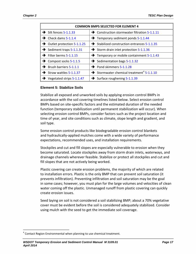
COMMON BMPS SELECTED FOR ELEMENT 4
Silt fences 5-1.1.33 Construction stormwater filtration 5-1.1.11
Check dams 5-1.1.4 Temporary sediment ponds 5-1.1.44
Outlet protection 5-1.1.25 Stabilized construction entrances 5-1.1.35
Sediment traps 5-1.1.31 Storm drain inlet protection 5-1.1.36
Filter berms 5-1.1.15 Temporary or mobile containment 5-1.1.43
Compost socks 5-1.1.5 Sedimentation bags 5-1.1.32
Brush barriers 5-1.1.1 Pond skimmers 5-1.1.28
Straw wattles 5-1.1.37 Stormwater chemical treatment4 5-1.1.10
Vegetated strips 5-1.1.47 Surface roughening 5-1.1.39
Element 5: Stabilize Soils
Stabilize all exposed and unworked soils by applying erosion control BMPs in accordance with the soil covering timelines listed below. Select erosion control BMPs based on site-specific factors and the estimated duration of the needed function (temporary stabilization until permanent stabilization will occur). When selecting erosion control BMPs, consider factors such as the project location and time of year, and site conditions such as climate, slope length and gradient, and soil type.
Some erosion control products like biodegradable erosion control blankets and hydraulically-applied mulches come with a wide variety of performance expectations, recommended uses, and installation requirements.
Stockpiles and cut and fill slopes are especially vulnerable to erosion when they become saturated. Locate stockpiles away from storm drain inlets, waterways, and drainage channels wherever feasible. Stabilize or protect all stockpiles and cut and fill slopes that are not actively being worked.
Plastic covering can create erosion problems, the majority of which are related to installation errors. Plastic is the only BMP that can prevent soil saturation (it prevents infiltration). Preventing infiltration and soil saturation may be the goal in some cases; however, you must plan for the large volumes and velocities of clean water coming off the plastic. Unmanaged runoff from plastic covering can quickly create erosion issues.
Seed laying on soil is not considered a soil stabilizing BMP; about a 70% vegetative cover must be evident before the soil is considered adequately stabilized. Consider using mulch with the seed to get the immediate soil coverage.
4 Contact Region Environmental when planning to use chemical treatment.

TESC Plan Design Chapter 2
Page 18 WSDOT Temporary Erosion and Sediment Control Manual M 3109.01 April 2014
Control stormwater volumes and velocity within the site to minimize erosion. Whenever feasible, minimize the total amount of open and actively worked soil at one time and the disturbance of slopes during the wet season.
Preserve topsoil whenever feasible, and minimize soil compaction in areas that will be permanently vegetated.
Stabilize equipment staging, material storage, borrow areas, and construction haul roads.
Expose no more soil than can be covered within the soil covering time limits below. Per Standard Specification 8-01.3(1), exposed soil that is not being worked by hand or machinery must be covered—whether at final grade or not—within the following time limits, using approved soil cover practices:
Western Washington:
October 1 through April 30 2-day maximum May 1 through September 30 7-day maximum
Eastern Washington:
July 1 through September 30 10-day maximum October 1 through June 30 5-day maximum
Central Basin of eastern Washington (areas with 12 inches or less of annual rainfall):
July 1 through September 30 30-day maximum October 1 through June 30 15-day maximum
For precipitation maps: www.wsdot.wa.gov/design/hydraulics/
If any portion of the project lies in areas that receive more than 12 inches of annual precipitation, follow the soil coverage time limits for eastern Washington, not for the Central Basin (contact Region Hydraulics to confirm average annual rainfall).
Walking or driving over exposed soil is not considered working an area. Maximum time limits for all soil cover practices are defined in calendar days. A calendar day is a period of 24 consecutive hours starting at midnight and ending the following midnight.
Construction activities should never expose more erodible earth than the amounts shown below for the specified locations. If the contractor feels that the area limitation for grubbing is too restrictive, submit a request for approval to open a larger area, and include a plan and schedule for any additional BMPs that may be necessary to manage increased erosion-related risks. Evaluate the contractor’s request for increased areas in consultation with Region Environmental staff. Work progress is of critical importance and should not be impeded except when clear probability of detrimental erosion potential exists or where permit constraints may be violated. (See to Chapter 2 of the Construction Manual for more information.)

Chapter 2 TESC Plan Design
WSDOT Temporary Erosion and Sediment Control Manual M 3109.01 Page 19 April 2014
Area Date Location
17 Acres April 1 – October 31 May 1 – September 30
East of the Summit of the Cascade Range West of the Summit of the Cascade Range
5 Acres November 1 – March 31 October 1 – April 30
East of the Summit of the Cascade Range West of the Summit of the Cascade Range
The CSWGP requires that a risk analysis be done for the work that will be performed and that BMPs be used to manage those risks. If work plans change, reflect the change in the TESC plan narrative or contract plan sheets. For example, if the project falls behind or gets ahead of schedule and more soil is open during the wet season than was originally planned, update the TESC plan to reflect the change in risk and the management practices being used (never disturb more acreage than what is permitted).
COMMON BMPS SELECTED FOR ELEMENT 5
Preserving natural vegetation 5-1.1.29 Sodding 5-1.1.34
Dust control 5-1.1.13 Check dams5 5-1.1.4
Erosion control blankets 5-1.1.14 Topsoiling 5-1.1.46
Mulching 5-1.1.24 Plastic covering 5-1.1.27
Temporary and permanent seeding 5-1.1.41
Hydraulically-applied erosion control products 5-1.1.19
Stabilized construction entrances 5-1.1.35
Construction road and parking area stabilization 5-1.1.9
Tackifiers and polyacrylamide6 5-1.1.40
Element 6: Protect Slopes
Design, construct, and manage cut and fill slopes to minimize erosion by the following:
Select BMPs based on the soil type and potential for erosion.
Reduce continuous length or gradient of slopes with terracing or diversions.
Add surface texture to slope to slow, disperse, or dissipate flows (e.g., blanket, mulch, compost sock).
Use top of slope BMPs to divert erosive flows away from the slope, such as interceptor dikes, swales, stabilized channels, or temporary pipe slope drains.
5 Check dams, brush barriers, straw wattles, and compost socks control flow rates and can help stabilize soils, but they are not considered soil-covering BMPs on their own. 6 Polyacrylamide (PAM) can help stabilize soils, but using it with mulch provides soil covering/additional protection.

TESC Plan Design Chapter 2
Page 20 WSDOT Temporary Erosion and Sediment Control Manual M 3109.01 April 2014
BMPs used to cover slopes, such as blankets and HECPs, do not hold up to concentrated flows, which is why you must use other BMPs to prevent concentrated flows from developing or hitting slopes. Use the design requirements in Chapter 5.
Manage overland flow or off-site water run-on to minimize erosion on slopes. Ensure concentrated flows or drips coming off overhead structures do not create erosion on slopes. Place excavated material on the uphill side of trenches, consistent with safety and space considerations.
If flow is from seeps or groundwater, use your best professional judgment in consultation with the Region Materials Engineer (RME) when sizing slope drains.
COMMON BMPS USED FOR ELEMENT 6
Pipe slope drains 5-1.1.26 Subsurface drains 5-1.1.38
Straw wattles7 5-1.1.37 Compost socks6 5-1.1.5
Mulching 5-1.1.24 Level spreaders 5-1.1.21
Temporary curbs and water bars 5-1.1.42 Brush barriers5 5-1.1.1
Interceptor dikes and swales 5-1.1.20 Gradient terraces 5-1.1.16
Erosion control blankets 5-1.1.14 Plastic covering8 5-1.1.27
Conveyance channel stabilization 5-1.1.12
Hydraulically-applied erosion control products 5-1.1.19
Temporary and permanent seeding 5-1.1.41
Element 7: Protect Drain Inlets
Protect all operable storm drain inlets from sediment with approved inlet BMPs. Inlet protection devices must be capable of being maintained without losing sediment or material into the catch basin and must be inspected weekly to ensure discharge treatment is occurring. Inlet filter socks clog quickly and water simply bypasses the filter area and overflows without treatment. If the inlet filter sock appears clogged or the water is discharging through the overflow bypass as shown in Standard Plan I-40.20, replace the inlet sock.
Inlet filter socks only provide minimal treatment for discharges and, whenever feasible, should not be relied on as the sole method for minimizing sediment release. Use erosion control BMPs to prevent turbid water from being generated, and use diverting BMPs, like temporary curbs, to prevent turbid water from reaching inlets. Wherever feasible, use inlet covers or plugs to prevent turbid discharges, and implement a strategy to manage the resulting ponding water.
7 Check dams, brush barriers, straw wattles, and compost socks control flow rates and can help stabilize soils, but they are not considered soil-covering BMPs on their own. 8 Plastic covering increases flow rates; protect toe of slope areas.
Chapter 2 TESC Plan Design
WSDOT Temporary Erosion and Sediment Control Manual M 3109.01 Page 21 April 2014
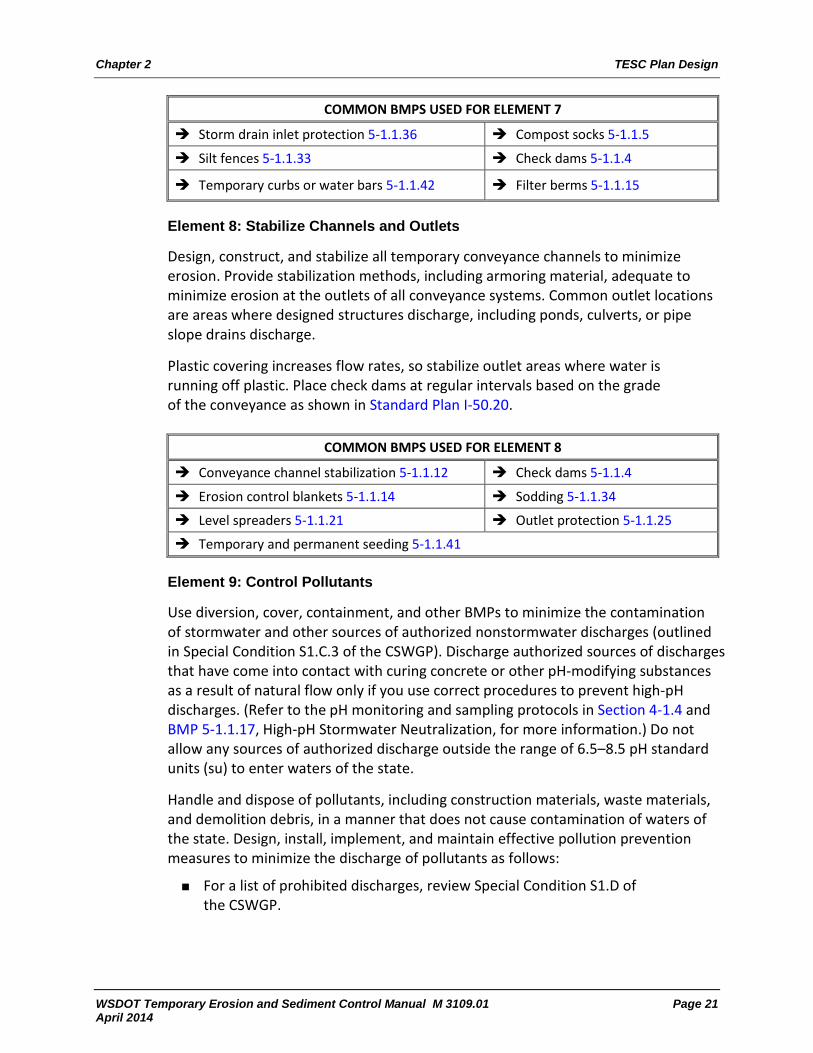
COMMON BMPS USED FOR ELEMENT 7
Storm drain inlet protection 5-1.1.36 Compost socks 5-1.1.5
Silt fences 5-1.1.33 Check dams 5-1.1.4
Temporary curbs or water bars 5-1.1.42 Filter berms 5-1.1.15
Element 8: Stabilize Channels and Outlets
Design, construct, and stabilize all temporary conveyance channels to minimize erosion. Provide stabilization methods, including armoring material, adequate to minimize erosion at the outlets of all conveyance systems. Common outlet locations are areas where designed structures discharge, including ponds, culverts, or pipe slope drains discharge.
Plastic covering increases flow rates, so stabilize outlet areas where water is running off plastic. Place check dams at regular intervals based on the grade of the conveyance as shown in Standard Plan I-50.20.
COMMON BMPS USED FOR ELEMENT 8
Conveyance channel stabilization 5-1.1.12 Check dams 5-1.1.4
Erosion control blankets 5-1.1.14 Sodding 5-1.1.34
Level spreaders 5-1.1.21 Outlet protection 5-1.1.25
Temporary and permanent seeding 5-1.1.41
Element 9: Control Pollutants
Use diversion, cover, containment, and other BMPs to minimize the contamination of stormwater and other sources of authorized nonstormwater discharges (outlined in Special Condition S1.C.3 of the CSWGP). Discharge authorized sources of discharges that have come into contact with curing concrete or other pH-modifying substances as a result of natural flow only if you use correct procedures to prevent high-pH discharges. (Refer to the pH monitoring and sampling protocols in Section 4-1.4 and BMP 5-1.1.17, High-pH Stormwater Neutralization, for more information.) Do not allow any sources of authorized discharge outside the range of 6.5–8.5 pH standard units (su) to enter waters of the state.
Handle and dispose of pollutants, including construction materials, waste materials, and demolition debris, in a manner that does not cause contamination of waters of the state. Design, install, implement, and maintain effective pollution prevention measures to minimize the discharge of pollutants as follows:
For a list of prohibited discharges, review Special Condition S1.D of the CSWGP.

TESC Plan Design Chapter 2
Page 22 WSDOT Temporary Erosion and Sediment Control Manual M 3109.01 April 2014
Concrete spillage and concrete wastewater are prohibited to discharge to waters of the state. Handle and dispose of concrete waste appropriately to prevent contamination. Refer to BMPs 5-1.1.7, Concrete Handling, and 5-1.1.8, Concrete Washout Areas, for more information.
Collect concrete slurry generated from cutting or grinding operations from the roadway on a continual basis immediately behind the operations, and dispose of in accordance with Standard Specification 5-01.3(11). Refer to BMP 5-1.1.6, Concrete Cutting and Grinding Pollution Prevention, for more information.
Apply fertilizers and other chemicals in a manner and at application rates that will not result in discharge of chemicals to stormwater runoff. Follow manufacturers’ requirements.
Discharge tire wash wastewater to a separate on-site treatment system that prevents discharge to surface waters, such as a closed-loop recirculation system or upland application. Do not use upland application if oil sheen or contaminated soils are present.
Send sources of prohibited discharges under the CSWGP to a sanitary sewer system, with prior local sewer district approval (see Section 4-1.6.9).
Handle pre-existing site contamination in accordance with contract documents.
Control Pollutants in the TESC plan
Outline methods for controlling nonhazardous sources of pollutants, such as loose soils or turbid stormwater/groundwater, and preventing high-pH discharges or other prohibited discharges. Planned work activity may trigger the development of additional plans to manage pollutant-generating work such as hydro-demolition (see Standard Specification 6-09.3(2)) or shaft drilling (see Standard Specification 6-19.3(2)).
Control Pollutants in the SPCC plan
Outline methods that will be used for controlling potentially hazardous materials, such as cementitious materials, petroleum products, and chemicals (defined in Chapter 447 of the Environmental Manual). Include strategies for cover, containment, and protection from vandalism for all hazardous materials, as well as secondary containment for on-site fueling tanks. Refer to BMP 5-1.1.22, Materials Handling, Storage, and Containment, for more information.
Ensure the SPCC plan is consistent with Standard Specification 1.07.15(1) and Ecology’s standards as described in WSDOT SPCC Plan Preparation Instructions and Spill Plan Reviewers Protocols: www.wsdot.wa.gov/environment/hazmat/spillprevention.htm

Chapter 2 TESC Plan Design
WSDOT Temporary Erosion and Sediment Control Manual M 3109.01 Page 23 April 2014
COMMON BMPS USED FOR ELEMENT 9
Concrete washout areas 5-1.1.8 Concrete handling 5-1.1.7
High-pH stormwater neutralization 5-1.1.17
Concrete cutting and grinding pollution prevention 5-1.1.6
Materials handling, storage, and containment 5-1.1.22
Element 10: Control Dewatering
Handle highly turbid or contaminated groundwater or dewatering water separately from stormwater. Uncontaminated dewatering water is an authorized nonstormwater discharge under the CSWGP. Manage, treat, and discharge these sources as described in Standard Specification 8-01.3(1)C. If dewatering water came into contact with pH-modifying substances, such a newly poured concrete foundation, as a result of natural flow, monitor pH levels to ensure high-pH water is not discharged. Follow the pH monitoring protocols outlined in Section 4-1.3.
COMMON BMPS USED FOR ELEMENT 10
Water pumps 5-1.1.49 Temporary or mobile containment 5-1.1.43
Element 11: Maintain BMPs
Ensure a Certified Erosion and Sediment Control Lead (CESCL) performs weekly site inspections per Standard Specification 8-01.3(1)B. Adapt the on-site TESC plan and BMPs on-site, and maintain them based on site conditions, weekly site inspection findings, and discharge sample values.
Maintain BMPs as needed to ensure functional performance in accordance with Standard Specification 8-01.3(15). Keep records on-site to document BMP implementation and maintenance (adaptive management) in the site log book. For more information, refer to Section 4-1.4 for adaptive management requirements and Section 4-1.5 for site log book requirements.
Stabilize sediments removed from BMPs away from drainages in an on-site area approved by the Project Engineer.
COMMON BMPS USED FOR ELEMENT 11
Materials on hand 5-1.1.23 CESCL 5-1.1.3

TESC Plan Design Chapter 2
Page 24 WSDOT Temporary Erosion and Sediment Control Manual M 3109.01 April 2014
Element 12: Manage the Project
Enforce the contract and apply the following actions on all projects:
Phase the work in accordance with the seasonal soil exposure limitations outlined in Standard Specification 8-01.3(1). If the contractor finds the exposure limitation too restrictive, they can submit a request to open a larger area, including a plan and schedule for any additional BMPs that may be necessary to manage the increased risks (see Chapter 2 of the Construction Manual for more information). Never allow the contractor to disturb more acreage than what was permitted.
Ensure sediment control BMPs are installed before construction begins in an area, to provide treatment prior to discharge.
Once construction begins, ensure the soil cover timelines are being followed in accordance with Standard Specification 8-01.3(1).
Coordinate the work of utility contractors and subcontractors to meet the requirements of the project permitting documentation.
Ensure weekly site inspections are being performed in accordance with Standard Specification 8-01.3(1)B.
Conduct weekly discharge sampling in accordance with Section 4-1, and report data collected for WSDOT-owned permits into the CWQM database at the end of every month to meet reporting deadlines.
Maintain a site log book that contains records of the permit requirements (see Section 4-1.5).
Ensure the CESCL is identified in the site log book and is on-site or on-call at all times during construction. Maintain current contact information for on-site CESCLs in the site log book.
Keep the updated TESC and SPCC plans in the site log book or reasonably accessible to the site (an electronic copy is allowed as long as it can be accessed on-site). Follow the TESC plan adaptive management requirements outlined in Section 4-1.4 and the site log book requirements outlined in Section 4-1.5.
COMMON BMPS USED FOR ELEMENT 12
Materials on hand 5-1.1.23 CESCL 5-1.1.3
Scheduling and coordinating work activity 5-1.1.30

Chapter 2 TESC Plan Design
WSDOT Temporary Erosion and Sediment Control Manual M 3109.01 Page 25 April 2014
Element 13: Protect Low-Impact Development BMPs
Protect low-impact development (LID) BMPs during construction activity to prevent impacts from sedimentation and soil compaction. If LID BMPs are impacted during construction, restore them to their original condition or design requirements.
Common LID BMPs (existing or installed during construction) that must be protected from construction activity include:
FC.01 – Natural Dispersion FC.02 – Engineered Dispersion RT.02 – Compost-Amended Vegetated Filter Strips (CAVFS) RT.04 – Continuous Inflow Compost-Amended Biofiltration Swale (CABS) RT.07 – Media Filter Drain (MFD) RT.08 – Bioretention Area IN.01 – Bioinfiltration Pond (E. WA only) Natural Depression Storage IN.02 – Infiltration Pond IN.03 – Infiltration Trench IN.04 – Infiltration Vault IN.05 – Dry Well
Design requirements for the above-listed LID BMPs are outlined in Chapter 5 of the Highway Runoff Manual.
COMMON BMPS USED FOR ELEMENT 13
High-visibility fencing 5-1.1.18 Compost socks 5-1.1.5
Silt fences 5-1.1.33 Buffer zones 5-1.1.2
Interceptor dikes and swales 5-1.1.20 Filter berms 5-1.1.15
Temporary curbs or water bars 5-1.1.42
2-1.3 Construction Schedule and BMP Implementation
When a TESC plan is included in the contract, the contractor is required to either adopt or modify the plan and provide a schedule for implementation of the plan per Standard Specification 8-01.3(1)A. The schedule should specify an implementation strategy to manage risks. The schedule should also include information about the following:
When and where soil-disturbing activities are scheduled to take place, and what sediment control and delineation devices will be required prior to the work.
Opportunities to phase work and/or modify the timing of clearing, grubbing, and grading activity to minimize soil exposure.
Provisional strategies for situations when the construction schedule might change or interfere with the placement BMPs.

TESC Plan Design Chapter 2
Page 26 WSDOT Temporary Erosion and Sediment Control Manual M 3109.01 April 2014
Strategies for transitioning from temporary BMPs to permanent BMPs, and opportunities to implement permanent BMPs early.
BMP maintenance needs.
Proactive communication and coordination between contractors and WSDOT personnel is essential to ensure permit requirements are met on day one of construction through final stabilization and permit termination. The following general scheduling guidelines can be used to track compliance-related activities:
1. Before construction begins, WSDOT verifies:
The CSWGP has been issued and the temporary outfall locations (as identified on the NOI) are correct and will cover all potential discharges from the project.
The TESC and SPCC plans are complete and a site log book has been compiled.
A CESCL has been identified to perform weekly site inspections and discharge sampling and the CESCL contact information is in the site log book.
The contractor has obtained permits for off-site staging/storage/ borrow areas.
If WSDOT owns the CSWGP, the project has been added to the Construction Water Quality Monitoring (CWQM) database.
Clearing limits have been marked and high-visibility fencing has been correctly installed to mark sensitive or protected areas.
Sediment control BMPs (e.g., detention ponds, inlet protection, check dams, construction entrances, silt fence, compost socks, and wattles) have been installed to provide treatment for potential discharges once construction begins.
2. As soon as construction begins, begin weekly discharge sampling/reporting and site inspections. Ensure all individuals collecting discharge samples or performing weekly site inspections are CESCL certified (see Section 4-1).
3. As construction progresses, adapt the TESC and SPCC plan as needed based on the site conditions, site inspections, or discharge sample values. Document BMP adaptive management on-site (see Section 4-1.4).
4. Once all construction is completed and the site is fully stabilized with permanent BMPs, remove temporary BMPs in accordance with Standard Specification 8-01.3(16) before applying to terminate the CSWGP (see Section 4-1.6.5).

Chapter 2 TESC Plan Design
WSDOT Temporary Erosion and Sediment Control Manual M 3109.01 Page 27 April 2014
2-1.4 Scoping and Budgeting
The scope of a TESC plan includes all phases of construction. Include each phase of a construction project in the risk analysis effort. Account for intermediate phases of construction and site configurations in the TESC scope. Consider inspecting and maintaining BMPs in scoping and budgeting, as well as repairing or replacing inadequate or malfunctioning BMPs.
Even with the best planning and risk assessment, there is still inherent risk associated with each project. For example, projects may encounter groundwater where it is not expected, soil conditions may be worse than anticipated, or the work schedule may be delayed into the wet season. In addition, extreme storm events cannot be forecasted but should be anticipated.
Budgeting methods for erosion control are not as defined as they are for more predictable construction activities. The Cost Estimating Manual for WSDOT Projects provides a consistent approach to cost estimating, estimate reviews, estimate documentation, and management of estimate date.
Erosion control efforts must be adapted throughout construction and often overlap with numerous other construction activities. Therefore, most erosion and sediment control efforts are paid through force account. The budgeting tools described below are intended to help when calculating the cost to install and maintain physical BMPs. One of the most accurate methods for calculating a TESC budget is to consult with technical personnel and specialists. Consult WSDOT personnel with experience on similar projects to confirm cost estimates for anticipated/selected BMPs.
2-1.4.1 Cost-Based Estimate
Calculate costs from the labor and materials costs for individual items. This method can be time consuming; however, it is the only method available for many of the newer TESC products.
2-1.4.2 Bid-Based Estimate
The HQ Design Office has tools for making bid-based estimates. Use the Unit Bid Analysis ( www.wsdot.wa.gov/biz/contaa/uba/bid.cfm) to view per-unit costs for specific standard bid items on past WSDOT projects. This method can quickly provide a price range for most common erosion control bid items.
TESC Plan Design Chapter 2
Page 28 WSDOT Temporary Erosion and Sediment Control Manual M 3109.01 April 2014
2-1.4.3 Construction Contract Information System
The HQ Construction Office maintains the Construction Contract Information System (CCIS), which contains cost information from past projects. Use this database to estimate future erosion control costs. If a project is being built in an area with a history of erosion challenges, query the database to view how much was estimated under the line items for Water Pollution Prevention/ Erosion Control and other commonly used TESC BMPs versus how much was actually spent. For instance, on some state routes and on some project types, WSDOT consistently pays more than it estimates for erosion control.
If the erosion control costs in an area are consistently greater than the estimates, consult the construction offices that experienced the cost overruns. Ask what factors caused the overruns, and incorporate extra measures into the erosion budget and the TESC plan to address problems and reduce such overruns on the upcoming project. Contact your local help desk or workstation support personnel to obtain access to CCIS.
2-1.5 Contract Enforcement
The contractual tools for ensuring the TESC plan is properly enforced include the Standard Specifications, statewide and region-specific General Special Provisions (GSPs), Special Provisions, and the Standard Plans.
Revisions are regularly made to the erosion control specifications in the Standard Specifications; however, they may not be adequate for site-specific needs and must be supplemented with GSPs or Special Provisions to ensure risks are addressed in the contract. For example, provisional contract language may be used to address management strategies for haul roads or the placement of tire washes. GSPs and Special Provisions have been written for many common erosion problems and can be pulled from existing libraries. The statewide library for GSPs and Special Provisions is provided on the HQ Design Office website: www.wsdot.wa.gov/business/construction/gsps.htm
Some regions have their own libraries of regional GSPs that can be accessed by contacting the Region Plans Office. If there is no suitable provision, one must be written. Staff within design, construction, and environmental offices can often help and should be consulted. The final approval of a project-specific special provision is by the Assistant Construction Engineer (ASCE) assigned to the project.
WSDOT Temporary Erosion and Sediment Control Manual M 3109.01 Page 29 April 2014
Chapter 3 SPCC Plans
3-1 Spill Prevention Control and Countermeasures Plan A spill prevention control and countermeasures (SPCC) plan is required on all projects in order to prevent and minimize spills that may contaminate soil or nearby waters of the state. The contractor prepares the SPCC plan in accordance with Standard Specification 1-07.15(1) and submits the plan to the Project Engineer to be reviewed and accepted before starting on-site construction activities. The Hazardous Materials and Solid Waste Program provides online guidance to contractors for preparing SPCC plans, and provides training to WSDOT staff on reviewing SPCC plans to ensure compliance with the following required elements:
Site information and project description
Spill prevention and secondary containment
Spill response procedures
Standby on-site material and equipment requirements
Reporting information
Program management
Plans to contain preexisting contamination, if necessary
Equipment for work below the ordinary high water line
Attachments, including a site plan and Spill and Incident Report forms
SPCC plans are required to be project-specific and must ensure the contractor:
Handles all pollutants in a manner that does not cause contamination of stormwater.
Covers, contains, and protects all materials from vandalism so that, if spilled, the materials would not pose an immediate risk to waters of the state.
Maintains and repairs heavy equipment using spill prevention measures such as drip pans and, if necessary, cover.
Applies fertilizers and herbicides following manufacturers’ recommendations, to protect runoff water quality.
Manages materials that modify pH, such as cementitious materials that contain Portland cement, fly ash, kiln dust, and bottom ash.
General Special Provisions (GSPs) may be included in a contract for project-specific pollution-prevention requirements (e.g., removal, containment, testing, and disposal requirements for contaminated soils or underground storage tanks). For additional SPCC guidance, see: www.wsdot.wa.gov/environment/hazmat/spillprevention.htm

SPCC Plans Chapter 3
Page 30 WSDOT Temporary Erosion and Sediment Control Manual M 3109.01 April 2014
Spill Response on WSDOT Construction Sites
In the event of a hazardous materials spill, release, or encounter by the contractor on a WSDOT construction site, personnel should notify the Project Engineer (PE) and refer to the SPCC plan for response activities. The response will depend on whether or not the spill or release enters waters of the state (ponds, wetlands, ditches, and seasonally dry streams) or soil.
In the event of a spill to waters of the state or the ground that may cause a threat to human health or the environment, notify Ecology immediately and submit a written report within 5 days in accordance with S5.f of the CSWGP. In addition, you must initiate the WSDOT Environmental Compliance Assurance Procedure (ECAP) to ensure proper notifications are made. Access the ECAP procedure information in the Construction Manual, Section 1-2.2K. Refer to the Spill Reporting Flow Chart on the Hazardous Materials Program website for contact information and detailed instructions on how to report spills or manage hazardous materials.
When contractors encounter unknown preexisting contaminants or underground storage tanks, or cause a spill that may be a threat to human health or the environment, they must stop work in the immediate area and notify the PE. The PE must evaluate the situation and initiate required notifications to regulating authorities and ECAP reporting.
Additional information for WSDOT staff regarding construction and hazardous materials is available at: http://wwwi.wsdot.wa.gov/environment/hazmat/

WSDOT Temporary Erosion and Sediment Control Manual M 3109.01 Page 31 April 2014
Chapter 4 Site Management, Reporting, and Compliance
4-1 Site Management and Discharge Sampling Monitoring is a broad site management activity, while weekly discharge sampling, reporting procedures, and TESC plan adaptive management are specific required actions. Monitoring construction activity helps identify potential compliance issues before they become a problem, such as:
High pH stormwater that must be neutralized prior to discharge.
New discharge points that need to be sampled and reported.
Lack of cover or containment that may lead to chemical or fuel spills.
Prohibited discharges, improper wastewater, or materials management.
Improperly installed/maintained or low-performing BMPs.
Potential impacts to protected or sensitive areas. Monitoring is usually done visually, but it may be enhanced by measuring the pH or turbidity of stormwater before it is allowed to discharge (predischarge). Do not report predischarge monitoring information as discharge data in CWQM.
4-1.1 Certified Erosion and Sediment Control Lead (CESCL)
Weekly site inspections and discharge sampling required by the CSWGP must be performed by a Certified Erosion and Sediment Control Lead (CESCL). CESCLs are expected to understand the site inspection and discharge sampling procedures and be capable of performing these weekly procedures in the field and reporting the data in a complete and timely manner. Refer to BMP 5-1.1.3, Certified Erosion and Sediment Control Lead (CESCL), for more information. Ecology maintains a list of people who are recognized as CESCL certified.
Internal CESCL training may be available for WSDOT staff; contact the HQ Erosion Control program for more information. If internal training is not available or convenient, external training can be used. The following conditions apply:
Becoming CESCL certified for the first time requires 16 hours of training (8 hours classroom and 8 hours field).
Individuals are not certified until both classes are completed within 6 months of each other.
Certifications must be renewed every 3 years within 6 months after the expiration date.
The 1-day WSDOT Construction Site Erosion and Sediment Control course will renew CESCL certifications for WSDOT staff.
Individuals who do not renew certifications within the 6-month window must take the 2-day CESCL training again.

Site Management, Reporting, and Compliance Chapter 4
Page 32 WSDOT Temporary Erosion and Sediment Control Manual M 3109.01 April 2014
4-1.2 Preparation for Discharge Sampling and Reporting
Monthly reporting requirements begin as soon as the CSWGP is issued by Ecology, even if construction has not yet started or a discharge has not occurred. Once construction begins, weekly site inspections and discharge sampling become required. Weekly site inspection guidelines are outlined in Section 4-1.4. Discharge sampling procedures for turbidity and pH from land-based construction are found in Section 4-1.3. Sampling procedures for in-water work are not covered in this manual but can be found in WSDOT’s Monitoring Guidance for In-Water Work document.
The CSWGP authorizes specific construction-related discharges to waters of the state, including stormwater and some nonstormwater sources such as uncontaminated groundwater, spring water, and landscape irrigation water (Special Condition S1.C of the CSWGP). Discharges must not cause or contribute to a violation of surface water quality standards (Chapter 173-201A WAC), groundwater quality standards (Chapter 173-200 WAC), sediment management standards (Chapter 173-204 WAC), and human health-based criteria in the National Toxics Rule (40 CFR Part 131.36). In accordance with Chapter 90.48 RCW, when the permittee fully complies with all CSWGP requirements, compliance with water quality is presumed unless monitoring data or other information demonstrates otherwise.
The CSWGP prohibits specific discharges to waters of the state, including but not limited to, wastewater, concrete and cementitious materials, fuels, soaps, solvents, and chemicals that may pose a threat to human health or the environment (Special Condition S1.D of the CSWGP).
The following steps will help ensure the preconstruction monthly reporting requirements are not missed for projects with WSDOT-owned CSWGPs and projects are prepared for the discharge sampling requirements once construction starts.
Step 1 Communicate with the WSDOT Erosion Control Program
The WSDOT Erosion Control program uses the Construction Water Quality Monitoring (CWQM) database to manage data and electronically submit monthly reports to Ecology for WSDOT-owned CSWGPs. Projects are not required to collect discharge samples until construction begins. However, before construction begins, permitted projects must report on the expected start date.
To complete preconstruction monthly reports for newly permitted projects, the Erosion Control program needs projects to do the following:
Send the Erosion Control program a courtesy copy of the permit issuance letter from Ecology as soon as it is received so the project can be added to CWQM and monthly reporting can begin. Contact the Erosion Control program immediately if the project has not been added to CWQM by the time the first monthly report is due (the end of the first month in which the permit was issued).

Chapter 4 Site Management, Reporting, and Compliance
WSDOT Temporary Erosion and Sediment Control Manual M 3109.01 Page 33 April 2014
Once the permit is issued and before construction starts, keep the “Working Construction Start Date” updated on the Project Information tab in CWQM.
Step 2 Obtain and Learn How to Use Appropriate Sampling Equipment
It is recommended that WSDOT regions use the following sampling equipment for instructional consistency purposes; however, functionally equivalent equipment can be used. The following equipment was selected for the purpose of legal compliance and should be maintained according to manufacturers’ guidelines.
Procedures Equipment
Sample turbidity Hach Model 2100P or 2100Q portable turbidimeter
Sample pH Hach Model IQ125 miniLab pH meter HQ11D pH meter Wide-range pH strips for nonbuffered solutions
Collection methods Extendable rod with attached cup, scoop, or dust pan for collecting sheet flow, clean sample bottles, or containers
Rain measurement Rain gage – Tru-Check brand or equivalent
Field observations Field notebook, camera, personal protective equipment
Company Product Estimated Cost
Hach Company* (970) 669-3050 www.hach.com/
2100P Turbidimeter 2100Q Turbidimeter IQ125 miniLab pH meter or
HQ11D pH Meter with pHC301 liquid-filled pH electrode
$850 $930 $240 $500
Fisher Scientific* www.fishersci.com
ColorpHast Strips S60169 or similar $20 per pack
Grainger* www.grainger.com
EMD ColorpHast Strips 4YMV9 or similar
$20 per pack
*or any supply distributor of equivalent equipment
Equipment Calibration and Documentation
For data to be legally defensible, follow the manufacturers’ recommendations for calibration schedules and procedures. Most manufacturers also recommend a calibration verification procedure. The verification procedure is a quick way to verify equipment is still calibrated and ready to use. Additional calibration may be needed based on the results of a verification procedure (more than ± 5% off known value) or if data appears suspect.

Site Management, Reporting, and Compliance Chapter 4
Page 34 WSDOT Temporary Erosion and Sediment Control Manual M 3109.01 April 2014
Maintain an equipment calibration log and keep it in a convenient location (e.g., in the equipment case) so it can be updated and referred to as needed. Key factors for keeping sampling equipment in good working order are:
Use non-expired primary calibration standards to calibrate equipment.
Verify equipment calibration weekly, especially if equipment bumps around in a field vehicle or is used often.
Keep pH meter probes submerged in storage fluid when not in use so they do not dry out and break, or keep wide-range pH indicator paper in the turbidimeter case.
Clean sample vials with distilled water and glass-cleaning wipes or microfiber cloth; paper-based material will scratch glass and affect measurements.
Use proper storage and good housekeeping methods. Visually examine the inside of equipment for dirt or damage that may affect measurements. Use canned air or a Q-tip to clean any visible dirt or debris from inside the turbidimeter.
Replace glass sample vials for turbidimeter if they appear scratched or damaged.
Do not expose equipment or liquid standards to extreme temperatures.
Contact product manufacturer if technical assistance is needed.
Step 3 Sample Location Identification and Set-Up
WSDOT’s construction projects are often long, linear projects that cross multiple drainage basins. Sites with multiple catch basins, low points, or stream crossings will likely have multiple discharge points, which will require multiple sampling locations to be set up in the field and in the CWQM database, and marked on the TESC plan sheets. Keep in mind that once construction begins, sampling locations may change; they might go away or new ones might develop. Such changes require updates in the field, in the CWQM database, and on the TESC plan sheets. All sampling locations should be given unique names and be associated with a permitted temporary outfall location in CWQM for reporting purposes. Contact the WSDOT Erosion Control program for assistance with setting up sample locations in the field or in CWQM as needed.
Do not allow construction-related discharges to enter a receiving surface water body that is not covered by the issued permit. If needed, project staff must refer to the permitted temporary outfalls to receiving surface waters as identified in the Notice of Intent (NOI).

Chapter 4 Site Management, Reporting, and Compliance
WSDOT Temporary Erosion and Sediment Control Manual M 3109.01 Page 35 April 2014
Establish sampling locations where stormwater or authorized nonstormwater may:
Discharge offsite; or Enter surface waters of the state within the site; or Enter a storm sewer system that drains to waters of the state.
Discharge sampling occurs at the point of discharge to ensure the sample represents the quality of water leaving the construction site (represents the impact of construction on the runoff). When setting up sampling location stations in the field:
Mark all sampling locations in the field with labeled survey stakes and mark them on the TESC plan sheets. At least one sampling location must be set up in CWQM for day one of construction for reporting purposes, even if no discharge has occurred. Contact the WSDOT Erosion Control program if you need assistance.
Install BMPs as needed to manage, treat, or direct flows and minimize the locations where water discharges from the project. For example, sheet flows going to a stream can create multiple natural discharge points. Compost socks can be used to direct the sheet flows to one managed discharge sample location.
Identify new sample locations that may develop as construction progresses. Update the TESC plan sheets, mark locations in the field, add the location to CWQM, and begin to collect and report weekly samples.
For projects with temporary outfalls in segments of 303(d)-listed waters impaired for turbidity, fine sediment, high pH, or phosphorus, sample discharges and measure compliance in accordance with Special Condition S8 of the CSWGP. Contact the WSDOT Erosion Control program for assistance.
For projects with temporary outfalls in segments of a water body subject to a Total Maximum Daily Load (TMDL) with construction discharge sampling requirements, sample discharges and measure compliance in accordance with Special Condition S8 of the CSWGP. Contact the HQ TMDL Lead for assistance.
Contact Region Environmental and the HQ Erosion Control program for projects that require additional permit conditions or sampling procedures.

Site Management, Reporting, and Compliance Chapter 4
Page 36 WSDOT Temporary Erosion and Sediment Control Manual M 3109.01 April 2014
Figure 4-1 Common discharge sample locations.
Step 4 Learn the Standard Discharge Sampling Procedures
Allow discharges to flow directly into a clean sample bottle or collection device.
Do not introduce pollutants (e.g., dirty equipment or hands).
Collect samples that accurately represent the quality of the discharge.
Use properly calibrated equipment.
Measure samples as soon as possible (temperature can affect pH).
Wipe glass sample vials clear of fingerprints or other residue before inserting into a turbidimeter; use a glass cleaning cloth to prevent scratching.
Smoothly invert the sample vial several times to resuspend particulates before measuring the sample with the turbidimeter. Never shake sample vials because shaking creates small bubbles that can affect measurement.
If sample value is suspect, measure it again or verify equipment calibration.
Record sample values and relevant information, or take pictures (e.g., BMPs, weather, work in area, potential adaptive management strategies).
Be aware of personal safety and changing site conditions.
Contact the WSDOT Erosion Control program if assistance is needed.

Chapter 4 Site Management, Reporting, and Compliance
WSDOT Temporary Erosion and Sediment Control Manual M 3109.01 Page 37 April 2014
Discharge sampling is not required:
If construction has not started in any contributing areas to a discharge point.
In areas that have been confirmed as fully stabilized (construction is complete and all contributing areas are permanently stabilized). It is highly recommended that several weeks of discharge samples be collected before sampling is discontinued to confirm and document that permanent stabilization has actually been achieved.
For discharges that are sent directly to sanitary sewer systems (follow the sampling/reporting requirements in the sanitary permit, but do not report these as a discharge covered by a CSWGP in the CWQM database).
When there is no discharge during a calendar week (“no discharge” must be reported in CWMQ).
Outside normal working hours such as holidays, nights, and weekends.
During frozen or unsafe conditions (add a note explaining the circumstances in the Other Activity section of the Add Monitoring Data screen in CWQM).
Recommended field equipment checklist:
√ Clean containers, extendable sampling rod, scoop for shallow flows
√ Calibrated sampling equipment and wide-range pH indicator paper
√ Bottle of distilled water and glass wipes for cleaning sampling equipment
√ Personal protective equipment, boots, rain gear
√ Camera and cell phone
√ Weather-proof field notebook or data sheet for recording information
Step 5 Prepare a Site Log Book
The CSWGP requires a site log book to be maintained on-site with specific documents (see Section 4-1.5). The site log book should be established at the site as soon as possible and no later than day one of construction.
4-1.3 Discharge Sampling Requirements for Turbidity and pH
The following steps outline the requirements for CSWGP-related discharge sampling:
1. Certified Erosion and Sediment Control Lead (CESCL)
Ensure all staff collecting discharge samples have a current CESCL and are capable of:
Collecting and recording weekly samples in the field.
Using and maintaining equipment to collect turbidity and pH samples.
Site Management, Reporting, and Compliance Chapter 4
Page 38 WSDOT Temporary Erosion and Sediment Control Manual M 3109.01 April 2014
2. Follow Sampling and Reporting Procedures
Ensure all staff responsible for reporting discharge samples understand the reporting procedures and are capable of entering data in the CWQM database.
3. Identify Discharge Sample Locations
Set up sample locations where stormwater or sources of authorized nonstormwater (refer to Special Condition S1.C.3 of the CSWGP) may:
Discharge offsite; or
Enter surface waters of the state within the site; or
Enter a storm sewer system that drains to waters of the state.
If discharge locations change throughout construction, set up new sample locations in the field, mark them on the TESC plan sheets, and add them to CWQM.
4. Collect Turbidity Samples
All projects covered under a CSWGP must collect samples of stormwater (or sources of authorized nonstormwater discharges) at all discharge sample locations at least once every calendar week. Samples must be representative of the flow and characteristics of the discharge being sampled.
Develop a plan to ensure sampling is conducted consistently and according the procedures in this chapter. This may require the responsible staff to be aware of the weather forecast and collect samples at different times each week. Contact the Erosion Control program for guidance on sampling requirements.
Turbidity Benchmark and Trigger Values
The turbidity benchmark value is 25 nephelometric turbidity units (NTU), and the phone-reporting trigger value is 250 NTU. These values are not discharge limitations or water quality standards; they are used to indicate how BMPs are functioning and to trigger specific actions. Discharge samples are compared to these values to determine the level of required action:
Discharges between 0 – 25 NTU indicate that BMPs are functioning well and no additional action is needed beyond collecting and reporting the sample value.
Discharges between 25.1 and 249.9 NTU indicate that BMPs are not functioning as well as they should be and additional action is required (follow Step A below).
Discharges of 250 NTU or greater indicate the BMPs are not functioning and surface water quality impacts may occur; immediate action is required (follow Steps A and B).

Chapter 4 Site Management, Reporting, and Compliance
WSDOT Temporary Erosion and Sediment Control Manual M 3109.01 Page 39 April 2014
A. Required follow-up actions for discharge samples > 25 NTU:
i. Review the TESC plan and make appropriate revisions to strategies or BMPs within 7 calendar days of the discharge that exceeded the benchmark.
ii. Fully implement and maintain BMPs as soon as possible, but within 10 calendar days of the discharge. If installation of BMPs is not feasible within 10 calendar days, Ecology may approve additional time if an extension is requested within the initial 10-day response period.
iii. Document BMP adaptive management in the Site Log Book.
iv. Report all discharge samples in CWQM before the end of the month; always include notes about BMP adaptive management.
B. Required follow-up actions for discharge samples > 250 NTU:
i. Follow Step A above.
ii. Ensure Ecology is notified via the Environmental Report Tracking System (ERTS) within 24 hours of a discharge that is 250 NTU or more. Failure to call the ERTS hotline is a violation. The person designated to make this call must follow the High Turbidity Reporting instructions on Ecology’s website: www.ecy.wa.gov/programs/wq/stormwater/construction/
iii. Continue to sample (follow-up sampling) the discharge daily until:
1. Turbidity is 25 NTU or lower; or
2. The discharge is confirmed as stopped or eliminated.
3. Compliance with the water quality limit for turbidity is demonstrated:
a. No more than 5 NTU over background turbidity, if background is less than 50 NTU, or
b. No more than 10% over background turbidity, if background is 50 NTU or greater.
Note for 3 above: In-stream background sampling is not a replacement for discharge point sampling. A background (upstream) sample may be collected to document compliance with the water quality limit for turbidity, but a discharge point sample is still required to be collected for reporting purposes (the background sample can be added in the notes section of CWQM). Not all projects will have access to the receiving water to collect a background sample. Contact the Erosion Control program for where and when background sampling may be warranted.

Site Management, Reporting, and Compliance Chapter 4
Page 40 WSDOT Temporary Erosion and Sediment Control Manual M 3109.01 April 2014
iv. Initiate the internal Environmental Compliance Assurance Procedure (ECAP) so the PE can review the event and determine if a violation occurred. If a violation occurred, the ECAP must be completed. Information about the ECAP can be found in the Construction Manual, Section 1-2.2K.
5. Collect pH Samples
If construction will involve 1,000 cubic yards or more of a pH-modifying substance, conduct pH monitoring and discharge sampling as soon as the first cubic yard is poured or used and exposed to precipitation.
Continue monitoring pH levels and collecting discharge samples of potentially pH-affected runoff weekly throughout and after the concrete pour and curing period until the pH is consistently in the range of 6.5–8.5 standard units (su). Once the incorporation of all pH modifying substances is complete in a contributing runoff area, two weeks of naturally compliant discharge samples (runoff is between 6.5–8.5 without needing to be neutralized) is adequate to document compliance.
Use pH predischarge monitoring to evaluate stormwater that may have an elevated pH before it discharges. Conduct predischarge pH monitoring in stormwater collection areas that may be pH affected. You do not need to report predischarge monitoring information in CWQM; only discharge sample data is required.
Ensure pH discharge sampling occurs weekly at all discharge locations where pH-affected stormwater discharges from the project. Even if the stormwater has been neutralized and is known to be in the range of 6.5–8.5 su, ensure a discharge sample is collected, evaluated for pH, and reported in CWQM. Always accompany pH discharge sample values with a turbidity sample value. Do not allow stormwater or authorized nonstormwater with a pH outside of the 6.5–8.5 su range to discharge into waters of the state.
Common pH-modifying substances include, but are not limited to:
Portland cement or recycled concrete
Cement kiln dust, fly ash, bottom ash
Engineered or amended soils
Jet grout, shotcrete, soilcrete, soil cement, etc.
Chapter 4 Site Management, Reporting, and Compliance
WSDOT Temporary Erosion and Sediment Control Manual M 3109.01 Page 41 April 2014
Compliance Range Values for pH and Neutralization Methods
As soon as elevating pH levels become evident in authorized sources of discharge, implement a plan for managing the water:
Prevent pH-affected water (outside of the 6.5–8.5 su range) from discharging to waters of the state; and
If necessary, neutralize high-pH stormwater or authorized nonstormwater prior to a discharge using approved methods (see BMP 5-1.1.17, High-pH Stormwater Neutralization, for more information). Only use approved methods, as unapproved methods may cause pH to drop below 6.5 su.
6. Report Sample Data in CWQM at the End of Every Month
The CSWGP monthly reporting requirements begin as soon as the permit is issued by Ecology, even if construction has not yet started or if discharges have not yet occurred. A missed reporting deadline is a permit violation. Project offices must communicate with the Erosion Control program to ensure reporting deadlines are not missed (see Section 4-1.2, Step 1).
All discharge data and information about BMP adaptive management from projects with WSDOT-owned CSWGP must be entered into the CWQM database no later than the end of every month. Data for any given month is considered late if not entered by the first weekday of the following month. All permit requirements continue until the permit is terminated (see Section 4-1.6).
For every week of the month, at every discharge sample location, projects must either:
Report a discharge sample value: If the sample value is over 25 NTU, include a note about BMP
adaptive management. If the sample value is 250 NTU or higher, include a note clarifying
whether the discharge stopped or was eliminated, or collect and report daily follow-up samples until the discharge is 25 NTU or less.
Report “no discharge” if no discharge occurred for the reporting period.
Select a reason why samples were not collected and add a note of explanation (some reasons are permit violations). If sampling or reporting issues occur, contact the Erosion Control program immediately.
The HQ Erosion Control program reviews data in CWQM at the beginning of every month and may request additional information to help ensure data is complete and accurate prior to the final submission to Ecology. The data in CWQM is electronically submitted to Ecology every month. Failure to provide complete and accurate information is a permit violation.

Site Management, Reporting, and Compliance Chapter 4
Page 42 WSDOT Temporary Erosion and Sediment Control Manual M 3109.01 April 2014
Contact the Erosion Control program to get access to CWQM. Guidance about how to use CWQM is available in the database, on the Erosion Control program intranet page or SharePoint site. The Erosion Control program also provides periodic training for the CWQM database.
4-1.4 Site Inspections and TESC Plan Adaptive Management
The CSWGP requires weekly site inspections to include all areas disturbed by construction activities, on-site BMPs, and discharge points. Site inspections must be done at a minimum of once per week and within 24 hours of storm events that may have caused on-site erosion or a need to maintain on-site BMPs. Refer to Section 4-1.6 for inspection procedures on temporarily inactive sites.
Inspections must be performed by a person with a current CESCL certification. When WSDOT owns the CSWGP, contractor personnel perform the weekly site inspections in accordance with Standard Specification 8-01.3(1)B. WSDOT staff must ensure site inspections are done in accordance with the contract and:
Issues identified during site inspections (e.g., underperforming or lack of appropriate BMPs, new discharge locations) are fully resolved and implemented within 10 calendar days.
Issue resolutions (adaptive management) are documented on-site and the TESC plan (narrative or plan sheets) or SPCC plan has been updated accordingly.
Copies of all inspection reports are kept in the site log book (see Section 4-1.5).
Project staff should develop a process for tracking identified TESC issues to ensure they are being resolved within 10 days and the resolutions are documented. Some projects develop a run list of action items and completion due dates.
TESC Plan Adaptive Management
Adaptive management is a continual process that must occur whenever site conditions or discharge sample values require action to minimize risk or improve discharge quality. The on-site TESC plan must be updated to reflect current site conditions and BMP installations. The three most common reasons that trigger TESC plan adaptive management are:
Site monitoring or inspection findings
A change in work activity, site conditions, schedule, or design that impacts risk
A discharge sample over 25 NTU (see Section 4-1.3)

Chapter 4 Site Management, Reporting, and Compliance
WSDOT Temporary Erosion and Sediment Control Manual M 3109.01 Page 43 April 2014
When BMP adaptive management is required, identify a strategy and implement it in the field no later than 10 calendar days after the issue was identified. Update the on-site TESC plan (narrative or plan sheets), or SPCC plan, accordingly (by hand or electronically, as long as it can be accessed on-site). Always document what adaptive management was done and include a completion date. If effective adaptive management is not feasible within 10 calendar days, Ecology may approve additional time if an extension is requested within the initial 10 day timeframe.
4-1.5 Site Log Book
Large projects may need several site log books to contain all of the required information. Ensure all site log books are organized so information can be located easily. Site log book information may be kept electronically, but must be accessible on-site.
Maintain the on-site log book with the following items:
Permit issuance letter
Updated TESC plan, SPCC plan, other related plans (e.g., chemical treatment plan)
Discharge sampling data
Weekly site inspection reports
Documentation of TESC or SPCC plan adaptive management
Contact information for on-site CESCLs who perform sampling or site inspections
Other construction stormwater-related documents (e.g., sanitary sewer permit)
4-1.6 Miscellaneous Reporting and Compliance-Related Issues
4-1.6.1 Permit Violations
Noncompliant events (CSWGP violations) occur when the permittee fails to meet a permit requirement. Discharge exceedances of the turbidity benchmark (25 NTU) and the phone reporting trigger value (250 NTU) are not permit violations in and of themselves. The violation occurs in the actions (or lack of actions) before or after the discharge occurs (for example, when appropriate BMPs are not installed or when the required follow-up actions are not performed).
Noncompliant events may include, but are not limited to:
Failure to collect and report weekly discharge samples as required.
High-pH stormwater (or authorized nonstormwater) discharges.
Failure to perform required follow-up actions based on discharge sample values.

Site Management, Reporting, and Compliance Chapter 4
Page 44 WSDOT Temporary Erosion and Sediment Control Manual M 3109.01 April 2014
Failure to call the ERTS hotline within 24 hours of a discharge > 250 NTU.
Discharges to an outfall not covered by the issued permit.
Prohibited discharges and/or uncontained spills of hazardous material.
Violation of water quality standards or groundwater standards.
Notification from Ecology that a permit violation has occurred.
Exceedances of discharge limits for impaired receiving water bodies.
Unauthorized impacts to a wetland.
If a noncompliant event does occur, and the event may cause a threat to human health or the environment, notify Ecology immediately and submit a written report to Ecology within 5 calendar days (per Special Condition S5.f of the CSWGP). An event that may cause a threat to human health or the environment includes, but is not limited to:
Spills of fuels or toxic materials that cannot be readily cleaned up with the on-site spill kit.
Pond or slope failure that discharges significant amounts of sediment to fish-bearing surface waters or tributaries to fish-bearing surface waters.
Discharges that cause violations of surface or groundwater quality standards.
4-1.6.2 Environmental Compliance Assurance Procedure (ECAP)
The ECAP is an internal reporting procedure for tracking environmental commitments associated with noncompliant events. Initiate the ECAP immediately after a possible noncompliant event is identified. Refer to the Construction Manual, Section 1-2.2K, for ECAP procedure information. Note: Entering discharge sample data into CWQM is not the same as initiating ECAP.
4-1.6.3 Discharge Sampling Not Conducted
The CSWGP defines acceptable reasons for not collecting discharge samples in Special Condition S4.C. (e.g., unsafe or frozen conditions). However, reasons that are attributed to negligence or oversight are permit violations. If a discharge sample was not collected for a week in which a discharge did occur, the CSWGP requires that an explanation be provided in the monthly discharge monitoring reports (DMRs). Staff responsible for collecting discharge samples must always do their due diligence to collect a sample every week at all locations where a construction-related discharge occurs until the permit is terminated (see Section 4-1.6.5).
Chapter 4 Site Management, Reporting, and Compliance
WSDOT Temporary Erosion and Sediment Control Manual M 3109.01 Page 45 April 2014
4-1.6.4 Temporarily Stabilized Inactive Sites and Projects in Winter Shutdown
The CSWGP makes an important distinction between temporary stabilization and final stabilization. Sites have not reached final stabilization until all non-biodegradable temporary BMPs have been removed, construction is complete, and all soils are fully stabilized with permanent erosion control BMPs such as rock or vegetation.
Projects that have been temporarily stabilized for winter shutdown or inactivity may reduce site inspections to once a month per Special Condition S4.B of the CSWGP; however, weekly discharge sampling must continue to ensure on-site BMPs continue to function as required.
4-1.6.5 Notice of Termination
Final stabilization is achieved when all construction is complete, all nonbiodegradable temporary BMPs have been removed, and the site is fully stabilized with permanent BMPs (e.g., vegetative cover, riprap, concrete), which work to prevent erosion. BMPs that are designed to be left in place and biodegrade do not need to be removed if they do not interfere with WSDOT maintenance activity such as mowing or land use.
If the construction project covered by the CSWGP is complete and all soils are fully stabilized, and all nonbiodegradable temporary BMPs have been removed, the project should submit a Notice of Termination (NOT) to Ecology per Special Condition S10 of the CSWGP. Prematurely submitting the NOT is a violation of Special Condition S10. Ecology may request a site visit prior to terminating the CSWGP.
If Ecology does not request a site visit within 30 calendar days of receiving the NOT application, the CSWGP is considered terminated and all permit-related compliance activities can be discontinued. All CSWGP requirements, including sampling and reporting, must continue until the permit is terminated.
4-1.6.6 In-Water Work
Upstream and downstream sample data collected during in-water work projects covered by a 401 Individual Water Quality Certification must be reported directly to the certifying agency by the project office staff; the Erosion Control program will not submit in-water work data even if it is entered into CWQM. For guidance on in-water work (401 certifications or a Letter of Verification) or creating Water Quality Monitoring Pollution Prevention (WQMPP) Plans, refer to WSDOT’s Monitoring Guidance for In-Water Work document or the Environmental Compliance During Construction intranet page.

Site Management, Reporting, and Compliance Chapter 4
Page 46 WSDOT Temporary Erosion and Sediment Control Manual M 3109.01 April 2014
4-1.6.7 Impaired Receiving Waters
The federal Clean Water Act requires states to prepare a list of impaired water bodies that fail to meet water quality standards. If a water body segment does not meet water quality standards for a specific pollutant, it gets added to the Water Quality Assessment list as a Category 5 water body segment, known as the 303(d) list. The 303(d) list consists of water bodies for which Total Maximum Daily Loads (TMDLs) must be developed to address the water quality impairment. In Washington State, Ecology maintains the Water Quality Assessment list and develops TMDLs.
Projects can use the GIS Workbench to identify impairments before they complete a Notice of Intent (NOI) for the CSWGP. If projects propose to discharge to an impaired water body on the NOI, they will receive a Proposed New Discharge to an Impaired Water Body form from Ecology. Use the guidance on the TMDL intranet page for using the GIS Workbench to identify impairments or for filling out the form from Ecology.
Projects covered by a CSWGP that will discharge to a water body that is impaired for turbidity, fine sediment, phosphorus, or high pH will be required to sample discharges in accordance with Special Condition S8 of the CSWGP. When the CSWGP is issued, the permit issuance letter will include information about additional monitoring requirements for discharges to impaired receiving waters. If your project is covered by a NPDES Individual Construction permit, or if your permit includes discharge sampling requirements for 303(d) or TMDL-related impairments, contact the Erosion Control program as soon as the permit is issued.
4-1.6.8 Construction Projects Not Covered by a Construction Stormwater General Permit (CSWGP)
Projects under an acre that do not obtain CSWGP coverage are required to “comply with all Federal, State, tribal, or local laws, ordinances, and regulations that affect Work under the Contract” per Standard Specification 1-07.1. Washington State laws and regulations as codified in the Washington Administrative Code (WAC) and the Revised Code of Washington (RCW) provide specific requirements related to the protection of waters of the state (Chapter 173-201A WAC and Chapter 90.48 RCW). Remember that some projects may not be large enough to trigger permit coverage, but an abbreviated TESC plan is still be required (refer to Section 1-1). WSDOT project engineers and staff should enforce contract language that directs contractors on erosion and water pollution control requirements found in Sections 1-07 and 8-01 of the Standard Specifications.
When projects are not covered by a CSWGP, take measures to minimize discharges and prevent discharges where feasible. If discharges cannot be prevented, ensure they are managed to prevent impacts to waters of the state, and conduct visual monitoring. If a turbidity plume is visible in the receiving water, adapt the site controls or management practices immediately to eliminate the turbidity plume.
Chapter 4 Site Management, Reporting, and Compliance
WSDOT Temporary Erosion and Sediment Control Manual M 3109.01 Page 47 April 2014
4-1.6.9 Discharges to a Sanitary Sewer
Discharges to a sanitary sewer system are not covered by the CSWGP. Do not report sample information for water that is discharged to a sanitary sewer system in the CWQM database. Comply with the sampling and reporting procedures in the sanitary sewer permit issued by the local jurisdiction.
4-1.6.10 Other Applicable Regulations
The Endangered Species Act (ESA) is of concern for construction sites because of the potential adverse impacts to habitat. Such impacts could be determined to be a "take" under ESA; for example, the stranding of listed species behind erosion and sediment control BMPs could be considered a "take."
Other regulatory or agency conditions and permits may require implementing BMPs to control pollutants during construction, such as:
TMDLs or Water Cleanup Plans.
Hydraulic Project Approval Permits.
Remediation agreements for contaminated sites (such as Model Toxics Control Act or Voluntary Cleanup Program sites).
Local permits and approvals, such as clearing and grading permits.
Site Management, Reporting, and Compliance Chapter 4
Page 48 WSDOT Temporary Erosion and Sediment Control Manual M 3109.01 April 2014

WSDOT Temporary Erosion and Sediment Control Manual M 3109.01 Page 49 April 2014
Chapter 5 TESC Best Management Practices
5-1 Introduction The following descriptions are provided to aid in the selection of appropriate best management practices (BMPs) for construction stormwater pollution prevention planning and management. The NPDES Construction Stormwater General Permit (CSWGP) requires all known, available, and reasonable methods of pollution prevention, control, and treatment (AKART) to be implemented prior to a discharge of stormwater or authorized nonstormwater such as dewatered groundwater. BMPs must be installed to minimize the sources of pollutants and provide treatment prior to all discharges to minimize the release of pollutants. Weekly site inspections and discharge sampling are required throughout construction to monitor BMP effectiveness and discharge quality. If construction site discharges exceed the turbidity benchmark (25 NTU), BMP adaptive management becomes required.
Standard Specifications (from the Standard Specifications for Road, Bridge, and Municipal Construction) exist for most, but not all, BMPs. The Standard Specifications associated with each BMP are referenced in this section. Standard Plans (from the Standard Plans for Road, Bridge, and Municipal Construction) are referenced when applicable. Use General Special Provisions (GSP) and Special Provisions to ensure the other BMPs are effectively employed. Prior to writing a Special Provision, check the statewide library for existing GSPs and Special Provisions that can be used to satisfy project needs. Regional GSP libraries may also provide useful provisions. Contact Region Environmental staff or the Assistant Construction Engineer (ASCE) assigned to your project for assistance in identifying resources when preparing Special Provisions.
The Washington State Department of Ecology’s (Ecology’s) stormwater management manuals for western Washington (SWMMWW) and eastern Washington (SWMMEW) also contain information about approved BMPs in Washington State. All BMPs used on construction sites must be consistent with this chapter or the SWMMWW or SWMMEW. Experimental BMPs must be approved by Ecology before being used. The technical basis (e.g., scientific studies, reasoning, or modeling) for using the experimental practice must be documented in the on-site TESC plan or site log book. Ecology maintains a list of technologies and products that have been approved as equivalent to the BMPs listed in these manuals.
5-1.1 TESC BMPs
Source control BMPs work to minimize a specific source of pollution. In construction stormwater management, the most common pollutant is sediment. Source control BMPs are often called erosion control BMPs because they minimize erosion, the source of loose sediment. However, some BMPs work to minimize sources of other pollutants such as chemicals, fuels, and pH-modifying materials like concrete. Proper installation is vital for the success of erosion control BMPs; follow the guidelines outlined in this chapter to prevent BMP failure.
TESC Best Management Practices Chapter 5
Page 50 WSDOT Temporary Erosion and Sediment Control Manual M 3109.01 April 2014
Some BMPs, such as vegetation and check dams, provide some amount of source control and treatment.
Treatment BMPs work to manage or minimize the impacts of polluted water after it has been generated. Since the most common pollutant in construction stormwater management is sediment, treatment BMPs are often called sediment control BMPs, because they work to remove sediment from polluted water prior to a discharge. Some BMPs, like temporary curbs and pumps, don’t actually provide treatment, but they are used in the treatment process to route or divert polluted waters to a location where they will receive treatment.
On construction sites, sediment control (treatment) BMPs are always required to be in place before construction starts in an area so all potential discharges receive some level of treatment prior to a discharge. Proper installation and regular maintenance are both important for the performance of sediment control BMPs. As the BMPs trap, filter, or contain sediment, they lose their functional performance (they become clogged and polluted water will overflow).
Some of the following BMPs are also occasionally called design or procedural BMPs because they are not structural or designed structures, but they represent permit-required procedures that help manage risk proactively.
5-1.1.1 BRUSH BARRIERS
No Standard Specification exists.
Purpose
Brush barriers reduce the flow velocity and encourage sedimentation prior to discharge.
Additional Information
Brush barriers can be made of chipped site vegetation, live cuttings or fascines, or composted or wood-based mulch. If site vegetation is used, ensure invasive species are not included. Brush barriers can be enhanced or held in place with geotextile fabric or biodegradable fabric such as burlap and wooden stakes.
Brush barriers should:
Not be used to treat concentrated flows or a large amount of runoff.
Be installed on contours downslope of areas less than a quarter acre.
Be installed and maintained to prevent flows from going around, through, or under the barrier.

Chapter 5 TESC Best Management Practices
WSDOT Temporary Erosion and Sediment Control Manual M 3109.01 Page 51 April 2014
5-1.1.2 BUFFER ZONES
Standard Specifications 1-07.16(2) – Vegetation Protection and Restoration 1-07.16(2)A – Wetland and Sensitive Area Protection 8-01.3(1) – General
Purpose
A buffer zone is a strip of vegetation that will provide a protective buffer to reduce impacts to sensitive areas.
Additional Information
Install high-visibility fence in advance of clearing and grubbing to delineate sensitive or protected areas.
Use buffer zones along streams, wetlands, and other sensitive areas that need protection from runoff velocities and sedimentation. Incorporate buffer zones into the landscaping of an area. Do not use critical-area buffer zones as sediment treatment areas.
5-1.1.3 CERTIFIED EROSION AND SEDIMENT CONTROL LEAD (CESCL)
Standard Specification 8-01.3(1)B – Erosion and Sediment Control (ESC) Lead
Purpose
A CESCL is a designated person on a construction site covered by a CSWGP who is responsible for ensuring compliance with all local, state, and federal erosion and sediment control and water quality requirements.
Additional Information
A CESCL certification is required per the CSWGP for any person responsible for performing weekly site inspections or construction site discharge sampling. Ecology maintains a list of current CESCLs and training providers at: www.ecy.wa.gov/programs/wq/stormwater/cescl.html
CESCL certifications are valid for three years.
The on-site CESCL shall have the authority to act on behalf of the contractor or permittee and shall be available or on-call 24 hours a day during construction.
The on-site TESC plan shall include contact information for on-site CESCL(s).
TESC plan implementation and weekly site inspections shall be performed in accordance with Standard Specification 8-01.3(1)B.
TESC Best Management Practices Chapter 5
Page 52 WSDOT Temporary Erosion and Sediment Control Manual M 3109.01 April 2014
TESC plan adaptive management, on-site documentation requirements, discharge sampling, and reporting shall be performed in accordance with the TESCM.
5-1.1.4 CHECK DAMS
Standard Specifications 8-01.3(6) – Check Dams 9-14.5(4)A – Biodegradable Check Dam 9-14.5(4)B – Non-biodegradable Check Dam
Standard Plan I-50.20 – Check Dams on Channels
Purpose
Check dams reduce the velocity of concentrated flows, thereby reducing erosion within a conveyance channel and encouraging suspended sediment to settle out.
Additional Information
Do not install checks dams in a stream unless approved by the Department of Fish and Wildlife. Do not install check dams in wetlands without approval from a permitting authority. Do not place check dams below the expected backwater from any salmonid-bearing water between October 1 and May 31.
Create check dams with sand bags, compost socks, or rock berms. Note that prefabricated products also exist, such as water bladders and geotextile-encased products.
Ensure check dams are perpendicular to the flow of water and spaced at maximum so that the toe of the upstream dam is at the same elevation as the spill point of the downstream dam.
Ensure check dams are a maximum of 2 feet at center (spill point) and that the center is at least 12 inches lower than the outer edges.
Whatever material is used, ensure the cross section is gently sloped from the dam crest like a triangle. This minimizes undercutting at the downstream toe of the check dam (spillway) because water can flow over the face of the dam rather than falling directly onto the ditch bottom.
Select the material used to fill sand bags such that it does not contribute turbidity or create erosion.
Keep the center of the check dam lower than the outer edges at natural ground elevation to prevent flooding of roads, dikes, or other structures.
Place rock, geotextile, or erosion control blankets in the conveyance channel to reduce or eliminate scouring.

Chapter 5 TESC Best Management Practices
WSDOT Temporary Erosion and Sediment Control Manual M 3109.01 Page 53 April 2014
Note that, in some cases (consider fish trapping or maintenance needs), check dams can remain as permanent BMPs with very minor regrading.
Straw wattles do not work well as check dams because they are designed to be trenched in to prevent flows from going under them. Do not trench anything into a conveyance area because those areas will become vulnerable to erosion if concentrated flows develop.
As sediment builds up behind a check dam, the water will want to flow over or around the check dam causing erosion. Inspect check dams often and maintain as needed to ensure continued function.
Never use silt fence to create a check dam in areas with concentrated flows.
5-1.1.5 COMPOST SOCKS
Standard Specifications 8-01.3(12) – Compost Sock 9-14.5(6) – Compost Sock
Standard Plan I-30.40 – Compost Sock
Purpose
The main purpose of a compost sock is to provide sediment control prior to a discharge or to slow the velocity of flows on a slope. Compost socks can prevent concentrated flows from developing by dissipating energy and dispersing flows on a slope or along the edge of pavement.
Additional Information
Do not trench in compost socks like silt fence or wattles.
Use compost socks in place of silt fence in some areas where low stormwater flows are expected. They are especially useful near sensitive areas where soil disturbance should be kept to a minimum.
Note that compost socks work well as check dams because they become very heavy when wetted and make a good connection with conveyance bottoms.
Install compost socks perpendicular to flows and parallel to slope contours.
Note that the compost in the sock provides soil nutrients that help establish vegetation.

TESC Best Management Practices Chapter 5
Page 54 WSDOT Temporary Erosion and Sediment Control Manual M 3109.01 April 2014
5-1.1.6 CONCRETE CUTTING AND GRINDING POLLUTION PREVENTION
Standard Specifications 1-07.5 – Environmental Regulations 5-01.3(11) – Concrete Slurry
Purpose
Concrete resurfacing operations such as saw-cutting and grinding generate high-pH concrete slurry and process wastewater that contain fine particles of cementitious material. Concrete spillage or discharge to surface waters of the state is prohibited. Utilize management practices that minimize the potential impacts of concrete work on waters of the state.
Additional Information
Vacuum or otherwise remove slurry and cuttings from the roadway as they are generated during the resurfacing operations. Do not allow waste materials to remain on the roadway overnight.
Do not allow slurry and cuttings to drain to any natural or constructed conveyance system or discharge point. Catch basins may need to be temporarily plugged to prevent a discharge.
Dispose of concrete slurry, sawcutting material, and other cementitious waste generated during resurfacing operations in a way that will not cause a violation to water quality standards.
Do not allow process wastewater (the water portion of the waste) generated from hydro-demolition, resurfacing, or similar operations to drain to any natural or constructed conveyance system or discharge point. Process wastewater is a prohibited discharge.
Monitor work during resurfacing operations to ensure discharges do not occur. If potential impacts to surface water or groundwater quality standards develop, stop work immediately and install additional controls.
Refer to related BMPs, including: Concrete Handling (5-1.1.7) and Concrete Washout Areas (5-1.1.8).
Chapter 5 TESC Best Management Practices
WSDOT Temporary Erosion and Sediment Control Manual M 3109.01 Page 55 April 2014
5-1.1.7 CONCRETE HANDLING
Standard Specifications 1-07.5 – Environmental Regulations 1-07.15 – Temporary Water Pollution/Erosion Control
Purpose
Concrete work can generate high-pH water and byproducts that may contain fine particles that will cause a violation of water quality standards if discharged. Concrete spillage and wastewater discharge to surface waters of the state is prohibited and is a permit violation. Management practices shall be utilized to reduce the impacts of concrete work on waters of the state.
Additional Information
Do not wash out concrete trucks onto the ground or near storm drains, open ditches, streets, natural or constructed stormwater conveyances, or streams. Wash out concrete trucks at appropriate off-site facilities or in designated concrete washout areas on-site. Return unused or leftover concrete to the originating batch plant for recycling. Do not dump excess concrete on-site, except in designated washout areas.
Wash concrete truck chutes, pumps, internal parts, and hand tools in formed areas actively awaiting installation of concrete or asphalt. If no formed areas are available, dispose of washwater in designated washout areas designed and maintained to prevent discharge to waters of the state.
Do not allow wash-down from concrete aggregate areas to drain directly to surface waters or natural or constructed stormwater conveyances.
Use forms or solid barriers, such as pilings, for concrete pours within 15 feet of surface waters.
When feasible, schedule larger concrete pours for the dry season.
Use BMPs whenever feasible to prevent stormwater from coming into contact with freshly poured concrete and concrete waste. Always monitor for elevating pH levels in stormwater runoff, prevent high-pH stormwater from discharging, and collect discharge samples as required in this manual.
Refer to related BMPs, including: Materials Handling, Storage, and Containment (5-1.1.22), Concrete Cutting and Grinding Pollution Prevention (5-1.1.6), Concrete Washout Areas (5-1.1.8), and High-pH Stormwater Neutralization (5-1.1.17).

TESC Best Management Practices Chapter 5
Page 56 WSDOT Temporary Erosion and Sediment Control Manual M 3109.01 April 2014
5-1.1.8 CONCRETE WASHOUT AREAS
Standard Specification 1-07.5 – Environmental Regulations
No Standard Specification exists for concrete washout areas, so a Special Provision must be written.
Purpose
Concrete washout areas prevent or reduce impacts to waters of the state from concrete waste by conducting washout in designated areas.
Additional Information
Construction projects with concrete work must be prepared to manage washout materials appropriately. If excess concrete and washwater cannot be taken back to the concrete batch plant, designated washout areas must be located on-site and maintained to provide adequate holding capacity and to protect waters of the state. Follow these steps when designating and maintaining on-site washout facilities to help reduce impacts to waters of the state:
If less than 10 concrete trucks or pumpers need to be washed out, dispose of the washwater in a formed area awaiting a concrete pour or an upland disposal area where it will not contaminate surface or groundwater. Ensure the upland disposal site is at least 50 feet from sensitive areas such as storm drains, open ditches, or water bodies, including wetlands.
Perform concrete washout for more than 10 trucks or pumpers in designated areas such as lined containments or wash pans designed for concrete washwater. Ensure plastic lining material for containment is a minimum of 10 mil polyethylene sheeting and free of holes or other defects that compromise the impermeability of the material.
Do not wash out concrete trucks or dump excess concrete onto the ground or streets, or near storm drains, streams, or ditches.
Never drain designated washout areas to surface waters or natural or constructed stormwater conveyances.
Wash equipment that is difficult to move in areas that do not directly drain to natural or constructed stormwater conveyances or discharge points.
Chapter 5 TESC Best Management Practices
WSDOT Temporary Erosion and Sediment Control Manual M 3109.01 Page 57 April 2014
Size and maintain concrete washout facilities sufficiently to contain all liquid and concrete waste generated by washout operations. Inspect designated washout areas regularly to ensure they continue to function as required. Cover designated areas with plastic in advance of storms to prevent overflow. Clean washout facilities when 75% full.
Do not incorporate hardened concrete waste from washout areas into the site because it is not cured sufficiently. Dispose of hardened concrete waste per applicable solid waste regulations.
Refer to related BMPs, including: Concrete Handling (5-1.1.7) and Concrete Cutting and Grinding Pollution Prevention (5-1.1.6).
5-1.1.9 CONSTRUCTION ROAD AND PARKING AREA STABILIZATION
Standard Specifications exist for road stabilization materials, but a Special Provision must be written describing when, where, and how much material is to be used.
Purpose
Construction road and parking area stabilization is used to reduce erosion of temporary roadbeds or parking areas.
Additional Information
If the area will not be used for permanent roads, parking areas, or structures, you may use a 6-inch depth of hog fuel (but this is likely to require more maintenance). Whenever possible, place construction roads and parking areas on a firm, compacted subgrade.
Install the first lift as soon as possible on areas that will receive asphalt as part of the project.
Apply a 6-inch depth of 2- to 4-inch crushed rock, gravel base, or crushed surfacing base course immediately after grading or utility installation. A 4-inch course of asphalt-treated base (ATB) may also be used, or the road/parking area may be paved. It may also be possible to use cement or calcium chloride for soil stabilization. If cement is used, use BMPs to minimize the impact on stormwater and pH monitoring, and sampling must occur if stormwater discharges. Never use crushed concrete for road stabilization; the fine particulate will cause elevated pH issues in the runoff.
Carefully grade roadways to drain effectively. Drainage ditches are required on each side of the roadway in the case of a crowned section or on one side in the case of a super-elevated section. Use a sediment control BMP for drainage ditches.

TESC Best Management Practices Chapter 5
Page 58 WSDOT Temporary Erosion and Sediment Control Manual M 3109.01 April 2014
Rather than relying on ditches, you may be able to grade the road so that runoff sheet-flows into a heavily vegetated area with well-developed topsoil. If the vegetated area has at least 50 feet of vegetation, use the vegetation, rather than a sediment pond or trap, to treat runoff.
Protect storm drain inlets that receive runoff from temporary construction roadways to prevent sediment-laden water from entering the storm drain system.
Add crushed rock, gravel base, hog fuel, and so forth, as required to maintain a stable driving surface and to stabilize any areas that have eroded.
5-1.1.10 CONSTRUCTION STORMWATER CHEMICAL TREATMENT
No WSDOT Standard Specification exists, so a Special Provision must be written. Region Environmental staff and the HQ Environmental Services Office (ESO) must be notified of the intent to use chemical treatment to determine whether it is necessary.
Purpose
Chemical treatment can quickly remove fine suspended sediments, such as clay and silt that take a long time to gravity settle in ponds or do not filter out in standard BMPs like compost socks or silt fence. Their usage is warranted when:
Large volumes of highly turbid water cannot be prevented due to unusual circumstances (such as projects requiring large dewatering/horizontal drilling operations or slides), and there is no reasonable possibility of effectively employing any standard sediment control BMP or dispersal/ infiltration technique.
Chemical treatment system costs enable the recovery of costs by other means, such as accelerated construction rates.
Conditions of Use
Notify Region Environmental staff to ensure the environmental offices can:
Provide input on whether or not chemical treatment is necessary or appropriate.
Provide technical assistance.
Ensure Ecology is properly notified.
Track usage, effectiveness, and cost/benefit information.

Chapter 5 TESC Best Management Practices
WSDOT Temporary Erosion and Sediment Control Manual M 3109.01 Page 59 April 2014
If the project determines that chemical treatment will be used to treat construction stormwater, select an approved method and design the system to meet Ecology’s design, operational, and discharge requirements. Refer to Ecology’s SWMMWW, Volume II, BMP C250, for more information on Chemical Treatment. Use WSDOT’s internal guidance (found on the Erosion Control intranet page) for designing and operating chemical treatment systems.
Once you identify the methods and system design, notify Ecology prior to the discharge from a chemical treatment system (submit a Request for Chemical Treatment form).
Include the chemical treatment system information, including the chemical products being used, system design, and approved operator contact information in the TESC plan.
Additional Information
Discharges from chitosan-enhanced sand filtration (CESF) systems must remain 10 NTU or less; the benchmark values in the CSWGP are no longer used once chitosan is introduced.
Operators of chemical treatment systems need to have additional certifications or training.
Use of other chemical, such as PAM on soil, may affect the treatability and performance of chemical treatment systems.
Chemical treatment systems may require automated measuring or shutoff systems, calibrated dose rate mechanisms, extra containment, designed bypass, residual testing, and daily monitoring information.
5-1.1.11 CONSTRUCTION STORMWATER FILTRATION
No WSDOT Standard Specification exists, so a Special Provision must be written.
Purpose
Construction Stormwater Filtration is used to remove sediment from construction site stormwater ponds that cannot be removed through other conventional means.
Additional Information
Unlike chemical treatment, the use of construction stormwater filtration does not require approval from Ecology.
Two types of filtration systems may be applied to construction stormwater treatment: rapid and slow.

TESC Best Management Practices Chapter 5
Page 60 WSDOT Temporary Erosion and Sediment Control Manual M 3109.01 April 2014
Rapid sand filters are typically used for water and wastewater treatment. They can achieve relatively high hydraulic flow rates, on the order of 2 to 20 gallons per minute per square foot of filter area (gpm/sf), because they have automatic backwash systems to remove accumulated solids.
In contrast, slow sand filters have very low hydraulic flow rates, on the order of 0.02 gpm/sf, because they do not have backwash systems. To date, slow sand filtration has generally been used to treat stormwater. Slow sand filtration is mechanically simple in comparison to rapid sand filtration, but requires a much larger filter area.
Filtration Equipment – Sand media filters are available with automatic backwashing features that can filter to 50 µm particle size. Screen or bag filters can filter down to 5 µm. Fiber-wound filters can remove particles down to 0.5 µm. Filters should be sequenced from the largest to the smallest pore opening. Sediment-removal efficiency is related to particle size distribution in the stormwater.
Treatment Process Description – Stormwater is collected at interception point(s) on the site and diverted to a sediment pond or tank for removal of large sediment and storage of the stormwater before it is treated by the filtration system. The stormwater is pumped from the trap, pond, or tank through the filtration system in a rapid sand filtration system. Slow sand filtration systems are designed as flow-through systems using gravity.
If large volumes of concrete are being poured, pH adjustment may be necessary.
Filtration may also be used in conjunction with polymer treatment in a portable system to ensure capture of the flocculated solids.
Refer to Ecology’s SWMMWW, Volume II, BMP C251, for more information on Chemical Treatment.
5-1.1.12 CONVEYANCE CHANNEL STABILIZATION
There is no Standard Specification for conveyance channel stabilization, because multiple practices are used and many of the specific practices have Standard Specifications. Flexible liners such as erosion control blankets and vegetation (seeding or sod) have Standard Specifications. Rock is also used to stabilize conveyance channels. Check dams are used in channels to provide erosion and sediment control. If it is determined that a rigid liner such as concrete or pipe is necessary, contact the WSDOT HQ Design Office, Hydraulics Section. No WSDOT Standard Specification exists for solid liners, so a Special Provision must be written.
Chapter 5 TESC Best Management Practices
WSDOT Temporary Erosion and Sediment Control Manual M 3109.01 Page 61 April 2014
Purpose
Conveyance channel stabilization is used to stabilize a conveyance area to sufficiently prevent erosion for the design storm flow.
Additional Information
Temporary channels should be sized to convey expected flows as follows:
Eastern Washington should be designed to handle peak flows or volumes from the 6-month, 3-hour storm using a single-event model. The designer should consult the Region Hydraulics staff to determine whether a higher level of protection is needed beyond the 6-month, 3-hour storm due to the time of year for construction (freezing conditions and snowmelt), the downstream conditions, or the expectation that the project will last several construction seasons.
Western Washington should be designed to handle peak flows or volumes generated by the 10-year storm using 15-minute time steps predicted by MGSFlood.
Note: Always be sure to use the most recent guidance material when designing channels. The following guidance comes from the Hydraulic Engineering Circular No. 15 – Design of Roadside Channels with Flexible Linings, Federal Highways Department publication No. FHWA-IP-87-7.
Consider the following principles when designing stable channels:
Bare soil has very little resistance to erosion when subjected to concentrated flows. Protect channels to withstand expected erosive forces.
Limit flow velocities, if necessary, to prevent damage to channel liners.
Flexible liners are not as strong as rigid liners, but they are able to conform to changes in channel shape while maintaining the overall lining integrity. As a general guideline, use only rigid liners in channels with shear stresses exceeding 8 lb/ft2 or on slopes exceeding 10%, unless you use properly sized riprap. Table 5-1 summarizes the advantages and disadvantages of the two liner types.
The potential for erosion is based on the shear stress of flow, which is the force required to pull or peel (erode) material off the bottom or sides of a ditch. Calculate shear stress using the following formula:
Shear Stress = WHG
where: W = Weight of water (62.4 lb/ft3) H = Height of water in feet G = Channel gradient in ft/ft

TESC Best Management Practices Chapter 5
Page 62 WSDOT Temporary Erosion and Sediment Control Manual M 3109.01 April 2014
Note: Channel gradient and water height in this formula assume an unobstructed flow of water in the ditch.
Using shear stress to determine effective liner types:
Table 5-2 indicates the maximum shear stresses that several types of flexible liner materials can withstand. As a general guideline when rock lining is used, multiply the expected maximum shear stress by 3 to apply a 30% safety factor, to obtain the mean diameter of rock or riprap needed to stabilize the ditch. Manufacturers provide the shear strength ratings for erosion control blankets.
Base the selection of liner material on the maximum shear stress that products or specified rock sizes can withstand.
Sample calculation and product selection process:
What flexible liner materials are adequate to stabilize a ditch with a 3% slope and an expected flow depth of 1.5 feet?
Shear stress = (62.4 lb/ft3)(1.5 ft)(.03) = 2.81 lb/ft2
If rock is used, stone size should be a minimum mean stone size of at least 8.4 inches, because (2.81)(3.0 conversion factor) = 8.4.
Numerous erosion control blankets made of coir and synthetic turf reinforcement products could be substituted for rock with potentially significant cost savings. A well-established healthy stand of grass could also withstand the expected shear stresses in the ditch and help purify the runoff.
Consider coupling other BMPs with the channel lining to ensure channel stability. Check dams can greatly reduce the velocity of flowing water, thereby reducing shear stress. Check dams can prevent erosion until the permanent grass liner is established. Temporary slope drains provide rigid lined conveyances until the permanent rigid or flexible lined channels are completed.

Chapter 5 TESC Best Management Practices
WSDOT Temporary Erosion and Sediment Control Manual M 3109.01 Page 63 April 2014
Table 5-1 Flexible versus rigid lined conveyances.
Flexible Rigid Advantages Inexpensive to install and maintain (grass-
lined ditches are self-healing) Provide runoff treatment Allow some infiltration Cause less increase in peak flows
Advantages Maximize conveyance capacity using limited
space Fully effective immediately (no need to wait
for grass to grow) Can be designed to withstand any level of
shear stress Disadvantages Excessive flows can cause erosion Vegetation requires time to become
established Require more space Not to be used in channels where shear stress
exceeds 8 lb/ft2 or slopes exceed 10% (except riprap)
Disadvantages Expensive to build, maintain, and repair Increased peak discharge rates more likely
to cause downstream erosion Minimal, if any, infiltration No runoff treatment
Table 5-2 Maximum permissible shear stresses for flexible liners.
Liner Category Liner Type Permissible Shear Stress (lbs/ft2)
Bare soil – No liner Noncohesive soil 0.01–0.04 Cohesive soil up to 0.1
(noncompacted)/ up to 0.8 (compacted) Erosion control blankets (temporary/permanent)*
Jute 0.45–1.0
Curlex wood or straw 1.0–2.5 Coir 2.0–4.0 Organic, synthetic, or mix 10.0–12.0 Vegetative** Uncut stand 2.1–3.7 Cut grass 0.6–1.0 Gravel/riprap 1-inch 0.33 2-inch 0.67 6-inch 2.0 12-inch 4.0
*Permissible shear stresses based on products chosen at random to give a general idea of blanket strengths by material type. This table does not reflect the full range of permissible shear stresses for each product type. **Varies with type and density of grass stand.

TESC Best Management Practices Chapter 5
Page 64 WSDOT Temporary Erosion and Sediment Control Manual M 3109.01 April 2014
5-1.1.13 DUST CONTROL
Standard Specifications 2-07.3 – Construction Requirements 8-01.3(2)E – Soil Binders and Tacking Agents
Purpose
Dust control is used to minimize the creation or movement of dust.
Additional Information
All soil covering BMPs used to stabilize soil will also minimize the creation of dust. Additional BMPs that minimize dust include the following:
Limit clearing to areas where immediate activity will take place.
Construct natural or artificial windbreaks or windscreens.
Spray the site with water until the surface is wetted, but do not create a discharge.
Note that used oil is prohibited as a dust suppressant. Local governments may approve dust palliatives (such as calcium chloride).
Lower speed limits or use paved routes.
Upgrade the road surface strength by improving particle size, shape, and mineral types that make up the surface and base materials.
Add surface gravel to reduce the source of dust emission. Limit the amount of fine particles (those passing a #200 screen) to 10% to 20%.
Use geotextile fabrics to increase the strength of new roads or roads undergoing reconstruction.
Restrict use by tracked vehicles and heavy trucks to prevent damage to the road surface and base.
Remove mud and other dirt promptly from wheels so it does not dry and turn into dust; sweep paved areas.
Limit dust-causing work on windy days.
Note that compliance with the local air pollution control authority constitutes compliance with this BMP.

Chapter 5 TESC Best Management Practices
WSDOT Temporary Erosion and Sediment Control Manual M 3109.01 Page 65 April 2014
5-1.1.14 EROSION CONTROL BLANKETS
Standard Specifications 8-01.3(3) – Biodegradable Erosion Control Blanket 9-14.5(2) – Biodegradable Erosion Control Blanket
Standard Plans I-60.10 – Biodegradable Erosion Control Blanket Placement for Slopes I-60.20 – Biodegradable Erosion Control Blanket Placement for Ditches
Purpose
Erosion control blankets protect soil from raindrop and sheet erosion until permanent vegetation is established. Blankets are often used to minimize erosion on slopes steeper than 3H:1V or in areas with channelized flow. Thick or textured blankets can capture small amounts of sediment (treatment). When choosing a product, considerations must be made for soil type, climate, and slope/conveyance gradient.
Additional Information
Depending on the composition of the blanket and environmental conditions, biodegradable blankets can remain intact from 6 months to 5 years. Fully biodegradable blankets do not need to be removed at the end of construction because they are intended to provide temporary cover and then degrade as vegetation grows. Biodegradable blankets are typically made of jute, straw, wood strands, coconut fiber (coir), or various combinations of each and are held together with biodegradable netting.
Synthetic blankets, often called turf reinforcement mats, contain materials that resist ultraviolet light, last more than 5 years, and should not be used under most circumstance for temporary erosion control (may be prescribed for permanent soil stabilization after geotechnical analysis).
Blanket netting can trap ground-dwelling wildlife such as snakes. Some blankets are woven together, so netting is not needed to hold the blanket together. If endangered species are present that are vulnerable to this type of entrapment, do not use a netted blanket.
Installation is the key to success with blankets. Blankets that are not installed correctly can cause big erosion events because problems go unseen (under the blanket). Follow the manufacturers’ recommendations for product placement and stapling.
Prepare slopes (smooth, uniform surface) prior to blanket installation so the blanket makes contact with the entire soil surface when secured.
Note that seeding occurs before the blanket is installed unless an open weave blanket is used, with 60% or more open area so seed can contact soil.
TESC Best Management Practices Chapter 5
Page 66 WSDOT Temporary Erosion and Sediment Control Manual M 3109.01 April 2014
Always consider the directional flow of water before installing a blanket. Anchor-trench blankets at the top of the slope to prevent water from undercutting the blanket. Place upslope sections over downslope sections like shingles on a roof.
Manually unroll blankets down the slope to prevent stretching or pulling out of the anchor trench. Do not walk on the installed blanket.
Note that typical staples are 6 inches long, metal, and U-shaped. Use longer, coiled, or barbed staples in sandy soils. Biodegradable staples are also available.
Follow the manufacturer’s recommendations for overlapping, staple, and check slot placement. If manufacturer’s recommendations are not provided with the product, follow Standard Plan I-60.10 for slopes or Standard Plan I-60.20 for ditches.
5-1.1.15 FILTER BERMS
Standard Specification 8-01.3(9)B – Gravel Filter, Wood Chips, or Compost Berm
Standard Plan I-80.10 – Miscellaneous Erosion Control Details
Purpose
Depending on the material used, filter berms can be used to manage or direct flows or to provide sediment control.
Additional Information
Route construction vehicles and equipment around filter berms, because they are easily damaged.
Note that you may need pipe slope drains to convey water that accumulates along the filter berm to prevent blowouts.
5-1.1.16 GRADIENT TERRACES
No Standard Specification exists, so a Special Provision must be written.
Purpose
Gradient terraces reduce erosion by intercepting surface runoff and conducting it to a stable outlet.

Chapter 5 TESC Best Management Practices
WSDOT Temporary Erosion and Sediment Control Manual M 3109.01 Page 67 April 2014
Additional Information
Do not construct gradient terraces on deep sands or soils that are too stony, steep, or shallow to allow practical installation and maintenance. Use gradient terraces only when suitable outlets are available.
Determine the maximum vertical spacing of gradient terraces by the following method:
VI = (0.8)s + y
where: VI = vertical interval in feet s = land rise per 100 feet y = a soil and cover variable with values from 1.0 to 4.0
Values of “y” are influenced by soil erodibility and cover practices. The lower values are applicable to erosive soils where little to no soil covering is on the surface.
Design gradient terraces in the following ways:
Increase vertical spacing determined by the above method as much as 0.5 feet or 10%, whichever is greater, to: provide better alignment or location, avoid obstacles, adjust for equipment size, or reach a satisfactory outlet. In the drainage area above the terrace, do not exceed the area that would be drained by a terrace with normal spacing.
Ensure the top of the constructed ridge is not lower at any point than the design elevation plus the specified overfill for settlement. The ridge height should include a reasonable settlement factor with a minimum top width of 3 feet at the design height.
Note that channel grades may be either uniform or variable with a maximum grade of 0.6 feet per 100 feet length (0.6%). For short distances, you may increase the grades to improve alignment. Ensure the channel velocity does not create erosion.
Include adequate outlets that prevent erosion.
Note that terraces should be able to handle the peak runoff expected from a 2-year, 24-hour design storm without overtopping.
Proportion the cross-section to fit the land slope.
Inspect gradient terraces after large storm events and maintain as needed to ensure continued function.
TESC Best Management Practices Chapter 5
Page 68 WSDOT Temporary Erosion and Sediment Control Manual M 3109.01 April 2014
5-1.1.17 HIGH-pH STORMWATER NEUTRALIZATION
Standard Specifications 1-07.5 – Environmental Regulations 1-07.15 – Temporary Water Pollution/Erosion Control 8-01.3(1)C – Water Management
Purpose
High-pH stormwater neutralization is used to treat authorized discharges in order to prevent high-pH discharges.
Additional Information
High-pH issues are commonly caused by cementitious materials such as concrete, Portland cement, recycled concrete, amended or engineered soils, mortars, grouts, materials that contain lime, fly ash, kiln dust, or bottom ash. The primary acidic agent in cement is calcium hydroxide (free lime).
If stormwater comes into contact with pH-modifying substances, they may become elevated in pH. When pH levels rise above 8.5, action becomes required to prevent a high-pH discharge. Cover, routing and diverting, and containment BMPs must be used to minimize the contact between stormwater and pH-modifying substances.
Stormwater that comes into contact with a pH-modifying substance as a natural course of work may require neutralization prior to being discharged to surface waters. Neutralization is a process used to lower the pH levels of authorized discharges to the acceptable range of 6.5 to 8.5 standard units (su). Only approved neutralization methods may be used. Discharge sampling must be performed in accordance with this manual. The infiltration of high-pH stormwater is only allowed in upland areas with soil types that allow all water to infiltrate (no surface runoff) without causing or contributing to a violation of groundwater standards.
Process wastewater generated as part of a construction process (e.g., concrete washout, hydro-demolition, shaft drilling) cannot be discharged to surface waters of the state even if it has been neutralized. Stormwater or groundwater that is used as part of a construction process becomes a process wastewater and therefore cannot be discharged to surface waters even if it is neutralized.
Process wastewater can be sent to a sanitary sewer if the local authority has granted approval. Discharges to a sanitary system are not covered by the CSWGP (follow the reporting requirements of the local authority that owns the sanitary system). Wastewater treatment and technology is subject to change, and certain sources of process wastewaters may be infiltrated under some circumstances. Contact the Region or HQ Environmental Office for more information.
Chapter 5 TESC Best Management Practices
WSDOT Temporary Erosion and Sediment Control Manual M 3109.01 Page 69 April 2014
Dry ice and CO2 sparging are the approved methods for treating high-pH stormwater. Treatment methods are as follows:
Make every effort to isolate the high-pH water in order to treat it separately from other stormwater on-site.
Transfer water to be treated to the treatment structure (baker tank). Ensure treatment structure size is sufficient to hold the amount of water to be treated.
Sample the pH of the water. As a general rule, less CO2 is needed for clearer water.
In the pH adjustment structure (baker tank), add CO2 until the pH drops as close to 7 as practicable. Introduce compressed carbon dioxide gas using a carbon dioxide diffuser (located near the bottom of the tank).
Release water, making sure that deposited sediment does not discharge in the process.
Discharge water in a manner (e.g., dispersion, infiltration, or dilution in a pond or drainage system) that maximizes treatment potential prior to entering waters of the state.
Dispose of sludge as concrete waste. If several batches of water are undergoing pH treatment, you can leave sludge in the treatment structure. Dispose of sludge as necessary to ensure adequate storage volume and effective treatment.
Operator Records: Include a diagram of the monitoring and treatment equipment and a description of the pumping rates and capacity the treatment equipment is capable of treating. Keep a record in the site log book of the: estimated volume of water treated daily; pH of untreated water; amount of CO2 needed to adjust water as close to a pH of 7 as feasible; pH of treated water; and discharge point location and discharge sample values.
Refer to related BMPs, including: Concrete Washout Areas (5-1.1.8) and Concrete Handling (5-1.1.7).

TESC Best Management Practices Chapter 5
Page 70 WSDOT Temporary Erosion and Sediment Control Manual M 3109.01 April 2014
5-1.1.18 HIGH-VISIBILITY FENCING
Standard Specifications 1-07.16(2) – Vegetation Protection and Restoration 8-01.3(1) – General 8-01.3(9)A – Fencing 9-14.5(8) – High Visibility Fencing
Standard Plan I-10.10 – High Visibility Fence
Purpose
High-visibility fencing is used to prevent impacts to sensitive or protected areas.
Additional Information
Install high-visibility fencing in advance of clearing and grubbing to delineate sensitive or protected areas. The high-visibility orange color is intended to draw attention to a protected area. Use high-visibility (orange) silt fence only in sensitive or protected areas where turbid runoff is a concern; ensure it is trenched in to provide sediment control (Standard Plan I-30.16 or I-30.17).
5-1.1.19 HYDRAULICALLY-APPLIED EROSION CONTROL PRODUCTS (HECPS)
Standard Specifications 8-01.3(2)D – Mulching 8-01.3(2)E – Tackifiers 9-14.4(2)C – Short-Term Mulch 9-14.4(2)B – Moderate-Term Mulch 9-14.4(2)A – Long-Term Mulch
Purpose
Hydraulically-applied erosion control products (HECPs) are a combination of organic fiber and tackifiers (and sometimes seed and fertilizer), which are sprayed onto soil to provide temporary cover. They adhere to the top layer of soil and create a permeable crust so rain can infiltrate. HECPs do not prevent erosion in areas with channelized or concentrated flows.
Chapter 5 TESC Best Management Practices
WSDOT Temporary Erosion and Sediment Control Manual M 3109.01 Page 71 April 2014
Additional Information
Most HECP products require a 24–48-hour cure time (no heavy rain) before they effectively adhere to the top layer of soil and create a permeable crust. They must dry to fully cure. The longer-term products are more expensive, but some include cross-linking fibers or fast-curing polymers, so the product can be applied in advance of precipitation or during light precipitation. WSDOT’s Qualified Products List (QPL) contains approved HECP products.
Proper installation is the key to success with these products. If feasible, construction inspectors should be present when the HECP is being sprayed to ensure:
Appropriate application rate is used.
The HECP is applied from multiple angles to prevent shadow areas (thinly covered areas or areas where soil shows through). Shadow areas will lead to product failure.
No more than 2,000 pounds per acre are applied in any single layer. This allows the first layer to dry before a second layer is applied and prevents slumping of the mulch and proper curing.
Covered areas are not walked on after installation. Breaks in crust coverage will lead to product failure.
The products are not used on saturated soils, areas with groundwater seeps or seasonal springs, or soils dominated by rock larger than 1-inch in diameter.
The manufacturers’ recommendations for installation are followed. There are many different HECP products on the market, so following recommendations is very important.
5-1.1.20 INTERCEPTOR DIKES AND SWALES
No WSDOT Standard Specification exists, so a Special Provision must be written. Size interceptor dikes and swales (see Table 5-3) to handle expected flows:
Eastern Washington should be designed to handle peak flows or volumes from the 6-month, 3-hour storm using a single-event model. The designer should consult the Region Hydraulics staff to determine whether a higher level of protection is needed beyond the 6-month, 3-hour storm due to the time of year for construction (freezing conditions and snowmelt), the downstream conditions, or the expectation that the project will last several construction seasons.

TESC Best Management Practices Chapter 5
Page 72 WSDOT Temporary Erosion and Sediment Control Manual M 3109.01 April 2014
Western Washington should be designed to handle peak flows or volumes generated by the 10-year, 15-minute flow rate predicted by MGSFlood. Note: MGSFlood currently gives 1-hour flow rates. To convert from 1-hour to 15-minute flow rates, a correction factor of 1.3 (multiplied to 2-year, 1-hour flow rate) and 1.6 (multiplied to 10-year, 1-hour flow rate) must be applied.
Purpose
Interceptor dikes and swales are used to intercept runoff and/or groundwater from drainage areas on slopes and direct it to a stabilized outlet.
Additional Information
Use the dike and swale to intercept the runoff from unprotected areas and direct it to areas where erosion can be controlled. This can prevent runoff from entering the work area or sediment-laden runoff from leaving the construction site.
Note that, when placed horizontally across a disturbed slope, the dike and swale reduces the amount and velocity of runoff flowing down the slope.
Stabilization of the dike and swale with temporary or permanent vegetation depends on soil characteristics and gradient. You may not need to apply a higher level of protection to low-gradient, highly porous soils, because much of the water infiltrates the ground, reducing erosion potential.
Use swale protection, check dams, or level spreaders on steeper grades.
Provide energy dissipation measures at the swale outlet.
Release sediment-laden runoff to a sediment-trapping facility.
Minimize construction traffic over temporary dikes. Use temporary cross culverts for channel crossing.

Chapter 5 TESC Best Management Practices
WSDOT Temporary Erosion and Sediment Control Manual M 3109.01 Page 73 April 2014
Table 5-3 Dike and swale design criteria.
Interceptor dikes meet the following criteria:
Top width 2 feet (600 mm) minimum. Height 18 inches (450 mm) minimum. Measured from upslope toe and at a
compaction of 90% ASTM D698 standard proctor. Side slopes 3H:1V or flatter. Grade Topography dependent, except that dike is limited to grades between 0.5
and 1.0%. Horizontal spacing of Slopes <5% = 300 feet (90 m) interceptor dikes Slopes 5–10% = 200 feet (60 m) Slopes 10–40% = 100 feet (30 m) Stabilization Slopes = <5%. Seed and mulch applied within 5 days of dike construction. Slopes = 5–40%. Dependent on runoff velocities and dike materials.
Stabilization, using either sod or riprap, should be done immediately to avoid erosion.
Outlet The upslope side of the dike must provide positive drainage to the dike outlet. No erosion can occur at the outlet. Provide energy dissipation measures as necessary. Sediment-laden runoff must be released through a sediment-trapping facility.
Other Minimize construction traffic over temporary dikes.
Interceptor swales meet the following criteria:
Bottom width 2 feet (600 mm) minimum; the bottom is level. Depth 1 foot (300 mm) minimum. Side slope 3H:1V or flatter. Grade Maximum 5%, with positive drainage to a suitable outlet (such as a sediment
trap). Stabilization of swale bottom and side
Seed per Standard Specification 8-01.3(2). Temporary seeding, or riprap 12 inches (300 mm) thick, pressed into the bank and extending at least 8 inches (200 mm) vertical from the bottom. slopes
Swale spacing Slope of disturbed area: <5% = 300 feet (90 m) 5–10% = 200 feet (60 m) 10–40% = 100 feet (30 m) Outlet Level spreader or riprap to stabilized outlet/sedimentation pond.

TESC Best Management Practices Chapter 5
Page 74 WSDOT Temporary Erosion and Sediment Control Manual M 3109.01 April 2014
5-1.1.21 LEVEL SPREADERS
No WSDOT Standard Specification exists, so a Special Provision must be written.
Purpose
A level spreader is used to: convert concentrated runoff to sheet flow and release it onto areas stabilized by existing vegetation or engineered filter strips; provide a temporary outlet for dikes and diversions consisting of an excavated depression constructed at zero grade across a slope.
Additional Information
Use above areas that are stabilized by vegetation. If the level spreader has any low points, flow will concentrate, creating channels and possibly causing erosion.
Use when a concentrated flow of water needs to be dispersed over a large area with existing stable vegetation.
Use only where the slopes are gentle, the water volume is relatively low, and the soil will absorb most of the low-flow events.
Use above areas that are stabilized by vegetation.
Note that, if the level spreader has any low points, flow will concentrate, creating channels and possibly causing erosion.
Design the level spreader so that runoff does not reconcentrate after release unless intercepted by another downstream measure.
Ensure level spreaders consisting of gravel or organic material have a minimal amount of fine particles that could negatively influence turbidity.
Ensure the spreader spans the full width of the channel. Use multiple spreaders for higher flows.
Ensure the depth of the spreader, as measured from the lip, is uniform across the entire width.
Set level spreaders back from the property line unless there is an easement for flow.
Chapter 5 TESC Best Management Practices
WSDOT Temporary Erosion and Sediment Control Manual M 3109.01 Page 75 April 2014
5-1.1.22 MATERIALS HANDLING, STORAGE, AND CONTAINMENT
Standard Specifications 1-06.4 – Handling and Storing Materials 1-07.5 – Environmental Regulations 1-07.15(1) – Spill Prevention, Control, and Countermeasures (SPCC) Plan
Purpose
Materials handling, storage, and containment are used to prevent or reduce the risk of a discharge of hazardous pollutants.
Additional Information
Handle the following common construction site materials with extra precautions to prevent contamination:
Petroleum products
Soil stabilizers, binders, and tackifiers (e.g., Polyacrylamide)
Fertilizers, pesticides, and herbicides
Detergents, soaps, and solvents
Cementitious materials such as Portland cement or grouts
Hazardous chemicals such as acids, adhesives, paints, and curing compounds
Take the following steps to minimize risk:
Minimize the storage of hazardous materials on-site whenever feasible, and store materials in designated areas.
Locate storage of hazardous materials away from waterways or discharge points such as storm drains.
Supply Material Safety Data Sheets (MSDS) for all materials stored, and keep chemicals in their original labeled containers.
Minimize long-term storage of hazardous materials whenever feasible, and handle as infrequently as possible.
Store materials in a covered area during the wet season.
Do not store hazardous materials directly on the ground; always use appropriately-sized secondary containment.
Liquids, petroleum products, and substances listed in 40 CFR Parts 110,117, or 302 shall be stored in approved containers and drums, and shall not be overfilled. Containers and drums shall be stored in temporary secondary containment facilities.
TESC Best Management Practices Chapter 5
Page 76 WSDOT Temporary Erosion and Sediment Control Manual M 3109.01 April 2014
Temporary secondary containment facilities shall:
Provide for a spill containment volume able to contain 10% of the total enclosed container volume of all containers, or 110% of the capacity of the largest container within its boundary, whichever is greater.
Be impervious to the materials stored therein for a minimum contact time of 72 hours.
Be maintained as leak free and be covered during nonworking days in the wet season. If containment devices fill with rainwater, the water shall be collected or removed so the required storage capacity is maintained. Removed or collected liquids shall be handled as hazardous waste unless testing determines otherwise.
Be placed in the field to allow for easy access and responsive cleanup times.
Spill kits should contain materials appropriate for the work being done and the potential spill-related risks. Contents for a typical spill kit include:
One (1) – Water-resistant nylon bag
Three (3) – Oil-absorbent socks 3” x 4’
Two (2) – Oil-absorbent socks 3” x 10’
Twelve (12) – Oil-absorbent pads 17” x 19”
Three (3) – Pairs of nitrile gloves
Ten (10) – Disposable bags with ties
Instructions
5-1.1.23 MATERIALS ON HAND
Purpose
Materials on hand keep BMPs readily available and on-site so they can be implemented quickly when BMP adaptive management becomes required.
Additional Information
Provide cover or appropriate storage methods for BMP materials that may break down when exposed to the elements (e.g., straw material and biodegradable netting).
The following BMPs can be implemented quickly, fulfill multiple needs, or require regular maintenance throughout construction, and therefore make sense to keep on hand in quantities dependent on the project:
Chapter 5 TESC Best Management Practices
WSDOT Temporary Erosion and Sediment Control Manual M 3109.01 Page 77 April 2014
Compost socks or wattles and stakes
Inlet protection devices
Weed-free straw
Plastic covering
Rock material
Silt fence and posts
Sandbags
Pumps and pipe
5-1.1.24 MULCHING
Standard Specifications 8-01.3(2)D – Mulching 9-14.4 – Mulch and Amendments
Purpose
Mulch provides immediate coverage and protects bare soil from raindrop erosion. Mulch also enhances seed germination and plant establishment by conserving moisture; holding fertilizer, seed, and topsoil in place; and moderating soil temperatures.
Additional Information
Table 5-4 provides additional information on some types of mulch material.

TESC Best Management Practices Chapter 5
Page 78 WSDOT Temporary Erosion and Sediment Control Manual M 3109.01 April 2014
Table 5-4 Mulch standard specifications and guidelines.
Material Application Rates Remarks Straw 9-14.4(1)
Approx. 2"–3" thick
Hand-spread straw generally requires greater thickness than blown straw. Hand-spread straw is less likely to be displaced by wind or runoff because of its weight and length. Blown straw should be held in place with a netting or tackifier to prevent displacement of mulch by wind and rain. Straw often introduces weed species. Certified Weed-Free Straw is required by 9-14.4(1). It should also not be used within the ordinary high-water elevation or in areas with concentrated flow (due to flotation). Straw mulch needs to be maintained often to be an effective soil cover and it may need to be removed for soil compaction purposes.
Short-Term Mulch 9-14.4(2)C
Approx. 1,500–2,000 lbs per acre: Apply per the manufacturer’s recommendations
Applied with a hydromulcher, often combined with seed and fertilizer. Contains a tackifier and requires a typical cure time of 24–48 hours before rain. Soil must be completely and uniformly covered, without shadow areas where soil shows through. These mulches do not hold up to concentrated flows. Under normal conditions, will last 3–6 months.
Moderate-Term Mulch 9-14.4(2)B
Approx. 3,000–4,000 lbs per acre: Apply per the manufacturer’s recommendations
Applied with a hydromulcher, often combined with seed and fertilizer. Contains a tackifier and requires a typical cure time of 24–48 hours before rain. Soil must be completely and uniformly covered, without shadow areas where soil shows through. Moderate-Term Mulch needs to be applied in more than one layer with no more than 2,000 pounds per acre in any one layer. These mulches do not hold up to concentrated flows. Under normal circumstances, will last 6–12 months.
Long-Term Mulch 9-14.4(2)A
Approx. 3,000–4,000 lbs per acre: Apply per the manufacturer’s recommendations
Applied with a hydromulcher, often combined with seed and fertilizer. May only require 2–4 hours of cure time. Soil must be completely and uniformly covered, without shadow areas where soil shows through. Long-Term Mulch needs to be applied in more than one layer with no more than 2,000 pounds per acre in any one layer. These mulches do not hold up to concentrated flows. Under normal circumstances, will last 12–18 months.
Compost 9-14.4(8)
2" minimum thickness
A “compost blanket” is often used to protect soils at final grades until permanent vegetation is planted because it can be directly seeded or tilled into soil as an amendment. Compost applied too thickly (over 3") on slopes may slide down as it becomes heavy when it absorbs water. If slopes are composted, it is best to till in the first lift or roughen the soil surface by cat-tracking or other means. Compost should not be applied in areas where water will sit for long periods of time because it will create a compost leachate that can elevate turbidity readings and nutrient levels in runoff. Do not use composted mulch near wetlands or nutrient-impaired waters.
Chipped Site Vegetation 2-01.2(3)
2" minimum thickness
A cost-effective way to dispose of debris from clearing and grubbing. If seeding is expected shortly after mulch, the decomposition of the chipped vegetation can create a nitrogen deficiency in the soil, making it difficult for grass to grow. It can be used where woody native vegetation will be planted. It is not recommended within 200 feet of surface waters. Wood chip mulch is also a suitable material for stabilizing entrances and haul roads that are not heavily used by construction vehicles. Special attention is needed to ensure invasive species are not being spread through this method.
Bark or Wood Chips 9-14.4(3) Wood Strand Mulch 9-14.4(4)
2" minimum thickness Approx. 100 tons per acre (approx. 800 lbs per cubic yard)
May be a suitable material for stabilizing entrances and haul roads that are not heavily used by construction vehicles. Wood material may need to be removed for compaction purposes and the structural integrity of roadways. The use of wood chip mulch ultimately improves the organic matter in the soil. However, if seeding is immediately expected, the decomposition of bark or wood chips can create a nitrogen deficiency, making it difficult for grass to grow. Wood chips can be used where native woody vegetation will be planted. Special attention is needed to ensure invasive species are not being spread through this method.

Chapter 5 TESC Best Management Practices
WSDOT Temporary Erosion and Sediment Control Manual M 3109.01 Page 79 April 2014
5-1.1.25 OUTLET PROTECTION
Standard Specification 8-01.3(11) – Outlet Protection
Purpose
Outlet protection is used to prevent erosion and scour at conveyance outlets and minimize the potential for downstream erosion by reducing the velocity of stormwater flows and discharges.
Additional Information
Note that common locations for outlet protection include discharge points for ponds, pipes, ditches, or other conveyances.
Size the scale of the outlet protection based on expected flow volumes and velocities.
Refer to the Hydraulics Manual for guidance in choosing appropriately-sized rock outlet protection or alternative materials.
5-1.1.26 PIPE SLOPE DRAINS
Standard Specification 8-01.3(14) – Temporary Pipe Slope Drain
Temporary pipe slope drains should be sized to handle expected flows:
Eastern Washington should be designed to handle peak flows or volumes from the 6-month, 3-hour storm using a single-event model. The designer should consult the Region Hydraulics staff to determine whether a higher level of protection is needed beyond the 6-month, 3-hour storm due to the time of year for construction (freezing conditions and snowmelt), the downstream conditions, or the expectation that the project will last several construction seasons.
Western Washington should be designed to handle peak flows or volumes generated by the 10-year, 15-minute flow rate predicted by MGSFlood. Note: MGSFlood currently gives 1-hour flow rates. To convert from 1-hour to 15-minute flow rates, a correction factor of 1.3 (multiplied to 2-year, 1-hour flow rate) and 1.6 (multiplied to 10-year, 1-hour flow rate) must be applied.
Purpose
Pipe slope drains are used to carry concentrated runoff down a slope without causing erosion or to minimize saturation of slide-prone soils.

TESC Best Management Practices Chapter 5
Page 80 WSDOT Temporary Erosion and Sediment Control Manual M 3109.01 April 2014
Additional Information
Pipe slope drains are often used at bridge ends to collect runoff and pipe it to the base of the fill slopes along bridge approaches. Another use is to collect runoff from pavement and pipe it away from side slopes. This is useful because there is often a time lag between installation of the first lift of asphalt and installation of curbs, gutters, and permanent drainage. Water can be collected and channeled to pipe slope drain inlets with sand bags, triangular silt dikes, berms, or other material.
If flow is exclusively surface water, use the design criteria contained in HRM Section 4-3.3 for western Washington or Section 4-4.3 for eastern Washington.
If flow is from seeps or groundwater, use best professional judgment in consultation with the Region Materials Engineer (RME) when sizing slope drains.
Use pipe slope drains when a temporary or permanent stormwater conveyance is needed to move the water down a slope to prevent erosion.
Use pipe slope drains at bridge ends to collect runoff and pipe it to the base of the fill slopes along bridge approaches. You can design these into a project and include them as bid items.
Use on road projects to collect runoff from pavement and pipe it away from side slopes.
Collect water and channel it to pipe slope drain inlets with sand bags, triangular silt dikes, berms, or other material.
Use temporary drains on new slopes.
Compact the soil around and under the pipe and entrance section to prevent undercutting.
Securely connect prefabricated flared inlet sections to the slope drain pipe.
Securely fasten multiple slope drain sections together, or use gasketed watertight fittings.
If 90° bends cannot be avoided in the drain pipe, install thrust blocks constructed from sandbags, “t” posts and wire, or ecology blocks to anchor the bends. For pipe slope drains that are to remain as permanent features, ensure the thrust block materials are capable of lasting for the expected life of the pipe.

Chapter 5 TESC Best Management Practices
WSDOT Temporary Erosion and Sediment Control Manual M 3109.01 Page 81 April 2014
Secure pipe along its full length to prevent movement (this can be done with steel “t” posts and wire). Install posts on each side of the pipe and wire the pipe to them. Do this approximately every 10–20 feet of pipe length, depending on the size of the pipe and quantity of water to be diverted.
Use pipe slope drains to convey water collected by interceptor dikes. Ensure the height of the dike is at least 1 foot higher at all points than the top of the inlet pipe.
Stabilize the area at the outlet with an energy-dissipating material (such as riprap).
If the pipe slope drain is conveying sediment-laden water, direct all flows into a sediment-trapping facility.
5-1.1.27 PLASTIC COVERING
Standard Specifications 8-01.3(5) – Placing Plastic Covering 9-14.5(3) – Clear Plastic Covering
Purpose
Plastic provides immediate soil coverage and prevents soil saturation. The primary uses for plastic are:
Coverage of temporary grade cut/fill slopes and stockpiles.
Temporary coverage of active work areas.
Protection of areas vulnerable to saturation.
Temporary liner for concrete washout areas or secondary containment.
Additional Information
Plastic prevents infiltration, which means 100% of rainfall is transferred to somewhere else. Therefore, plastic can create erosion issues quickly if not implemented with some foresight. Make a plan for managing the water coming off the plastic.
Key factors to remember when installing plastic:
Plastic will increase flow velocity, so use soil stabilization and energy dissipation BMPs to minimize the erosive energy of flows coming off sloped areas of plastic (e.g., toe of slope).
When feasible, prevent the clean runoff from plastic from hitting bare soil. Direct flows from plastic to stabilized outlet areas.
TESC Best Management Practices Chapter 5
Page 82 WSDOT Temporary Erosion and Sediment Control Manual M 3109.01 April 2014
Anchor plastic at the top of the slope and along seams to prevent water from going under the plastic. Place upslope sheets over downslope sheets like shingles on a roof.
Secure overlapping edges and terminal ends. Plastic can easily be blown off in wind and become a safety hazard for the traveling public.
Note that plastic is maintenance intensive, and it becomes brittle over time and develops holes and tears. The average cost per square yard of installed plastic is often greater than the cost of many erosion control blankets, especially when maintenance, removal, and disposal costs are added.
5-1.1.28 POND SKIMMERS
No Standard Specification exists, so a Special Provision must be written.
Purpose
Pond skimmers withdraw temporarily detained water from the top part of the water column to avoid sediment that may be suspended lower in the water column.
Additional Information
Pond skimmers are used to pump down water levels in sedimentation ponds to maintain storage capacity in a way that ensures the cleanest water is discharged in a controlled manner. Skimmer products can be purchased or made using floats and centrifugal pumps (submersible pumps create a vortex that can suck up settled sediments at the bottom of the pond or tank).
All discharges shall comply with the CSWGP and shall be controlled in a manner that will protect downstream properties and waterways from sedimentation and erosion related to increased velocity and peak volumetric flow rates.
5-1.1.29 PRESERVING NATURAL VEGETATION
Standard Specifications 1-07.16(2) – Vegetation Protection and Restoration 1-07.16(2)A – Wetland Sensitive Area Protection 8-01.3(1) – General
Purpose
Existing vegetation is the most effective and cheapest BMP available. Phasing work or minimizing exposed soils by clearing only where construction will occur will minimize erosion-related risks. Vegetation provides critical habitat and assists in controlling erosion, especially on unstable steep slopes.
Chapter 5 TESC Best Management Practices
WSDOT Temporary Erosion and Sediment Control Manual M 3109.01 Page 83 April 2014
Vegetation provides the following erosion control benefits:
Rainfall impact (energy) absorption
Reduction of runoff volumes and velocities
Sediment trapping
Root stabilization of soil
Additional Information
Install high-visibility fencing in advance of clearing and grubbing to delineate sensitive or protected areas.
Vegetation may be protected because it does not need to be removed as part of construction or because it is in a sensitive area or buffer zone. Do not use sensitive areas and buffer zones as treatment or infiltration areas. Check with the local jurisdiction or WSDOT environmental permitting staff.
5-1.1.30 SCHEDULING AND COORDINATING WORK ACTIVITY
Standard Specifications 1-08.3 – Progress Schedule 8-01.3(1) – General 8-01.3(1)A – Submittals
Purpose
Scheduling or coordinating construction activity in a way that will minimize environmental risks.
Additional Information
Managing a large construction project with multiple contractors is a major coordination challenge. Weekly meetings, progress reports and schedules, or other methods of consistent communication are vital. Developing and following a specified work schedule that coordinates the timing of land-disturbing activity with the installation of appropriate BMPs requires effective communication between environmental site inspectors, CESCLs, contractors, subcontractors, and the Project Engineer.
Construction practices that limit or phase land-clearing activity and provide timely installation of erosion and sediment control BMPs can significantly reduce potential environmental impacts. Sediment control (treatment) BMPs must be installed to protect potential discharge points prior to land-disturbing activity in an area. Whenever feasible:
Minimize grading or excavation work during the rainy season.
Phase work to minimize the total area of exposed soil at any one time.

TESC Best Management Practices Chapter 5
Page 84 WSDOT Temporary Erosion and Sediment Control Manual M 3109.01 April 2014
Install sedimentation ponds or detention facilities, stabilized construction, and sediment control BMPs prior to work in an area.
Practice staged seeding in order to revegetate areas as soon as possible.
5-1.1.31 SEDIMENT TRAPS
No WSDOT Standard Specification exists, so a Special Provision must be written.
Standard Plan I-80.10 – Miscellaneous Erosion Control Details
Purpose
Sediment traps are used to aid in the settling of suspended sediments from concentrated flows.
Additional Information
Intended for use on sites where the tributary drainage area is less than 3 acres, with no unusual drainage features and with a projected build-out time of 6 months or less.
Trap efficiency is enhanced when runoff is passed through multiple sediment control BMPs.
Sediment traps are limited to removing silt/larger-sized sediment particles.
Trap effectiveness increases with trap size.
1. Sizing Procedure
To determine the sediment trap geometry, first calculate the design surface area (SA) of the trap, measured at the invert of the weir. Use the following equation:
SA = FS(Q/Vs)
where: Q = Design inflow based on criteria below. Vs = The settling velocity of the soil particle of
interest. The 0.02 mm (medium silt) particle with an assumed density of 2.65 g/cm3 has been selected as the particle of interest and has a settling velocity (Vs) of 0.00096 ft/sec.
FS = A safety factor of 2 to account for non-ideal settling.
Therefore, the equation for computing surface area becomes:
SA = 2 x Q/0.00096 or 2,080 square feet per cfs of inflow
Chapter 5 TESC Best Management Practices
WSDOT Temporary Erosion and Sediment Control Manual M 3109.01 Page 85 April 2014
Note: Even if permanent facilities are used, they must still have a surface area that is at least as large as that derived from the above formula. If they do not, the pond must be enlarged.
Design Q for sizing:
Design Q for eastern Washington should be designed to handle peak flows from the 6-month, 3-hour storm using a single-event model. The designer should consult with Region Hydraulics staff to determine whether a higher level of protection is needed beyond the 6-month, 3-hour storm due to the time of year for construction (freezing conditions and snowmelt), the downstream conditions, or the expectation that the project will last several construction seasons.
Western Washington should be designed to handle peak flows generated by the 2-year storm using 15-minute time steps predicted by MGSFlood for the developed site condition without flow control. The designer should consult Region Hydraulics staff to determine if downstream conditions warrant a higher level of protection. The 10-year storm using 15-minute time steps flow rate should be used if the project is expected to last several construction seasons.
Ensure the sediment trap is at least 1.5 feet deep (see Figure 5-1).
To aid in determining sediment depth, ensure all sediment traps have a staff gage with a prominent mark 1 foot above the bottom of the trap (see Figure 5-2).
Note that sediment traps may not be feasible on utility projects due to the limited work space or the short-term nature of the work. Use portable tanks in place of sediment traps for utility projects.
Remove sediment from the trap when it reaches 1 foot in depth.
Repair any damage to the pond embankments or slopes.

TESC Best Management Practices Chapter 5
Page 86 WSDOT Temporary Erosion and Sediment Control Manual M 3109.01 April 2014
Figure 5-1 Sediment Trap Cross Section (from Ecology’s SWMMWW, 2012)
Figure 5-2 Sediment Trap Outlet (from Ecology’s SWMMWW, 2012)
5-1.1.32 SEDIMENTATION BAGS
No Standard Specification exists, so a Special Provision must be written.
Purpose
Sedimentation bags remove coarse sediment from turbid water before it receives additional treatment.
Additional Information
Sedimentation or filtration bags can only be used as a pretreatment BMP, meaning the water that filters through the bag should not discharge directly to surface waters, and additional treatment must be provided after the water leaves the bag. Sediment control BMPs must be in place protecting all potential discharge locations. Filtered water from the bag must not cause on-site erosion.

Chapter 5 TESC Best Management Practices
WSDOT Temporary Erosion and Sediment Control Manual M 3109.01 Page 87 April 2014
Base the selection of the bag product on pump flow rate, the amount and type of suspended sediment in the water, and permittivity of the bag. As the bag fills with sediment, take measures to prevent bag failure or bursting (e.g., reduce pump flow rate, maintain or replace bag). Stabilize uncontaminated dewatered sediment from the bag in a controlled upland location away from drainages.
Filter bags require the following:
Place at least 50 feet away from potential discharge locations.
Never place on slopes or on surfaces that may puncture the bag.
Install and maintain in accordance with manufacturers’ instructions, including recommended pump flow rates, sediment loading rates, and hose connections.
Ensure they are made from nonwoven, needle-punched polypropylene geotextile.
5-1.1.33 SILT FENCE
Standard Specification 8-01.3(9)A – Fencing
Standard Plans I-30.10 – Silt Fence with Backup Support I-30.15 – Silt Fence I-30.20 – Erosion Control at Culvert Ends I-40.10 – Temporary Silt Fence for Inlet Protection in Unpaved Areas
Purpose
Silt fences reduce the transport of coarse sediment from a construction site by providing a geotextile barrier that reduces velocities of sheet flow or shallow overland flow.
Additional Information
Silt fence can create serious erosion problems quickly if not properly installed. Do not install silt fence in areas that receive concentrated flows (over 0.5 cfs). Water filters through silt fence very slowly, too slowly to treat concentrated flow. Concentrated flows will overtop silt fence or collapse it altogether.
Trench in and install silt fence on the contour of the slope or it will create concentrated flow where there was none before.
Place fence below disturbed areas subject to sheet and rill erosion as a perimeter sediment control BMP.
Place fence on contour to maximize sediment-trapping performance.

TESC Best Management Practices Chapter 5
Page 88 WSDOT Temporary Erosion and Sediment Control Manual M 3109.01 April 2014
Never install silt fence in streams or in conveyances that have concentrated flows.
5-1.1.34 SODDING
Standard Specification 9-14.6(8) – Sod
Purpose
Sodding is used to establish permanent turf for immediate erosion protection or to stabilize areas where concentrated flow will occur (roots must be attached to underlying soil before erosion can be prevented in channelized areas with concentrated flows).
Additional Information
Place sod on soil areas where roots can penetrate and keep the sod healthy. Any sod that either does not attach to the soil or dies must be removed, because water can flow under the dead sod mats and create unseen erosion issues.
Note that sod provides instant soil coverage, and permanent stabilization should be achieved if the roots successfully attach to the soil.
In swales, place sod strips perpendicular to the flow of water to increase the ability to resist shear stress.
Stagger sod strips to produce a more stable soil cover.
5-1.1.35 STABILIZED CONSTRUCTION ENTRANCES
Standard Specification 8-01.3(7) – Stabilized Construction Entrance
Standard Plan I-80.10 – Miscellaneous Erosion Control Details
Purpose
Stabilized construction entrances are used to stabilize entrance and exit areas to reduce the amount of sediment track-out or transport onto public roads.
Additional Information
Use a stabilized rock pad underlain by geotextile fabric to stabilize entrance and exit areas. You can also use paved areas and steel rumble plates. Other allowable methods are installing the first lift of asphalt in areas that will be paved or using excess concrete left over from a large pour (monitor for elevated pH discharges if using concrete).
Chapter 5 TESC Best Management Practices
WSDOT Temporary Erosion and Sediment Control Manual M 3109.01 Page 89 April 2014
If a stabilized construction entrance/exit fails to prevent sediment track-out or transport, you must maintain or enhance it. You may need a tire wash facility or sweeping if track-out continues.
Traffic entering and leaving the site from the same access point may cause more track-out issues. Try to limit access points; consider restricting use of access points for one purpose (e.g., exit only and entrance only).
Include extra materials in the contract for large projects or projects with a lot of grading and hauling activity to maintain the entrance/exit areas.
If sediment is tracked off-site, street sweeping is required at the end of each day at a minimum, and more frequently if necessary to prevent turbid discharges. However, sweeping does not remove fine sediment particles from the roadway (sweepers that use water to wash the roadway remove more sediment and prevent dust); therefore, a rain event can still cause a turbid discharge. Source control, preventing the track-out in the first place, is always the goal. Street sweeping or cleaning is not a substitute for a stabilized construction entrance. Refer to Standard Specification 8-01.3(7) and the Standard Plans.
5-1.1.36 STORM DRAIN INLET PROTECTION
Standard Specification 8-01.3(9)D – Inlet Protection (below inlet grate, above inlet grate, and inlet grate cover)
Standard Plans I-30.40 – Compost Sock I-40.10 – Temporary Silt Fence for Inlet Protection in Unpaved Areas I-40.20 – Storm Drain Inlet Protection
Purpose
Storm drain inlet protection is used to prevent coarse sediment from entering an operational drainage system. Inlet protection is often the last opportunity to treat runoff prior to a discharge.
Additional Information
Inlet protection devices vary widely in their ability to capture sediment. In general, these devices clog quickly and do not provide a high level of treatment. They should not be relied on to clean up dirty water. Other BMPs must be used to minimize the turbidity of water going to inlets.
There is a difference in how internal and external inlet protection devices function.

TESC Best Management Practices Chapter 5
Page 90 WSDOT Temporary Erosion and Sediment Control Manual M 3109.01 April 2014
Internal devices tend to consist of a nonwoven material that is semiporous. Larger sediments are trapped, but silt and clay-sized particles pass through. They are most appropriate in situations where roadway flooding is a concern or construction traffic will damage an external device. Filtering devices, sometimes called “witches hats” clog quickly and need to be replaced often.
External devices may be prefabricated or assembled in the field using silt fence. Both types trap sediment by creating a ponding area surrounding the inlet. The reduced velocities allow sediment to settle. This process allows external devices to be more efficient at trapping greater volumes of smaller-sized sediment.
In an emergency, berms of sand bags or washed gravel can be placed around the inlet.
5-1.1.37 STRAW WATTLES
Standard Specifications 8-01.3(10) – Wattles 9-14.5(5) – Wattles
Standard Plan I-30.30 – Wattle Installation on Slope
Purpose
The two main purposes of wattles are to reduce flow velocity and to trap sediment. Wattles are used to break up the continuous length of a slope and to prevent concentrated flows from developing. They are also used as a sediment control device.
Additional Information
Trench in straw wattles to prevent flows from going under them. The lightweight springy nature of the straw material makes the staking and trenching installation absolutely necessary for performance.
Install wattles perpendicular to flows and parallel to slope contours.
Do not use straw wattles as check dams because straw wattles are designed to be trenched in to prevent flows from going under them. However, it is not a good idea to trench anything into a conveyance area because those areas will become vulnerable to erosion from the concentrated flows.

Chapter 5 TESC Best Management Practices
WSDOT Temporary Erosion and Sediment Control Manual M 3109.01 Page 91 April 2014
5-1.1.38 SUBSURFACE DRAINS, FRENCH DRAINS, AND SUMP SYSTEMS
No Standard Specification exists, so a Special Provision must be written.
Purpose
Subsurface drains, French drains, and sump systems are used to temporarily intercept and collect runoff or excessive groundwater and convey it in an underground conduit to a stabilized outlet, infiltration area, collection area, or an area where additional treatment will occur.
Additional Information
Determine the capacity of underground drainage systems by calculating the maximum rate of groundwater or overland flow to be intercepted. Ensure the drainage system has an adequate capacity and a stabilized outlet (e.g., by gravity or pumping) to manage flows.
Note that the minimum diameter for a subsurface drain pipe is 4”.
Grade the line to achieve a minimum velocity of 1.4 ft/sec. The maximum allowable velocity using a sand-gravel filter is 9 ft/sec.
Monitor and maintain collection points and outlet areas to ensure the drainage system is functioning as intended. Ensure the discharges from drainage systems do not cause polluted discharges, erosion, or a danger to the public.
5-1.1.39 SURFACE ROUGHENING
Standard Specification 8-01.3(2)A – Preparation for Application
Purpose
Surface roughening adds texture to the soil surface that will aid in the establishment of vegetation, reduce runoff velocity, encourage infiltration, and trap sediment.
Additional Information
Roughening methods include stairstep grading, grooving, contour furrows, and track walking. Factors to be considered in choosing a method are slope steepness, mowing requirements, and whether the slope is formed by cutting or filling. Surface roughening should be used in conjunction with soil-covering BMPs such as seeding and mulching.
Disturbed areas that will not require mowing (steeper than 3H:1V) may be stairstep graded, grooved, or left rough after filling.
Stairstep grading is particularly appropriate in soils containing large amounts of soft rock. Each step catches material that sloughs from above and provides a level site where vegetation can become established. Stairs should be wide enough to work with standard earth-moving equipment.

TESC Best Management Practices Chapter 5
Page 92 WSDOT Temporary Erosion and Sediment Control Manual M 3109.01 April 2014
Track walking texture must be parallel to slope contour.
Graded areas with slopes steeper than 3H:1V, but less than 2H:1V, should be roughened before seeding.
5-1.1.40 TACKIFIERS AND POLYACRYLAMIDE
Standard Specifications 8-01.3(2)E – Tackifier 9-14.4(7) – Tackifier 9-14.5(1) – Polyacrylamide
Purpose
Tacking agents such as Polyacrylamide (PAM) are used to hold soil or mulch in place and may provide other benefits. Tackifiers are used in erosion and sediment control applications because they work to bind soil particles, increase soil porosity, and reduce soil compaction, dust, and water runoff. Tacking agents can be organic (derived from plant sources) or synthetic polymers. PAM is a type of synthetic polymer and PAM-based products are the most commonly used tackifiers.
Special Conditions
Never apply PAM directly to water (e.g., added to a pond or introduced to water via a flow-through sock) without prior approval from Ecology. You may apply PAM to soil without prior approval from Ecology in accordance with these guidelines. The use of PAM may be restricted in a 401 Water Quality Certification.
Additional Information
PAM products must meet the ANSI/NSF Standard 60 for drinking water treatment and be anionic and linear (non-cross-linked). Never use cationic PAM, because it is known to cause aquatic toxicity. Approved PAM products are listed on the Qualified Product List in accordance with Standard Specification 9-14.5(1).
Measure the area where PAM is to be applied and calculate the amount of product and mixing water necessary to provide coverage at the specified application rate. Always add PAM to the mixing water; never add mixing water to PAM. Use mechanical mixing to help the PAM dissolve completely.
PAM works best when applied to dry soil, so apply PAM to bare soil in accordance with Standard Specification 8-01.3(2)E.
Ensure runoff from PAM-treated areas passes through sediment control devices that provide adequate opportunity for PAM-treated sediments to drop out before water discharges to surface waters:

Chapter 5 TESC Best Management Practices
WSDOT Temporary Erosion and Sediment Control Manual M 3109.01 Page 93 April 2014
If less than 5 acres of soil are treated with PAM, all runoff from treated areas must drain to sediment control BMP(s) that will allow enough time for sediment to settle out. For example, three check dams per acre treated, prior to discharge.
If 5 acres or more of soil have been treated with PAM, all of the runoff from the treated area must drain to a pond prior to discharge.
Use PAM in conjunction with, not as a replacement for, other BMPs. It also works well when used in conjunction with mulches.
Do not apply PAM to areas that flow directly into a surface water, including wetlands.
For small areas that need coverage, apply PAM at the dry application rate using a hand-held seed spreader.
Note that, depending on site conditions, PAM remains in the soil 3 to 6 months from the date of application. Extreme weather and heavy traffic (if used on haul roads) shorten the lifespan. These conditions require more frequent re-application.
Reapply PAM, if necessary, on actively worked areas after a 48-hour period.
PAM breaks down and loses its effectiveness when exposed to climatic conditions such as high or low temperatures and sunlight. Store PAM in an airtight container in secondary containment and out of the sun.
5-1.1.41 TEMPORARY AND PERMANENT SEEDING
Standard Specifications 8-01.3(2) – Seeding, Fertilizing, and Mulching 9-14.2 – Seed
Purpose
A well-established vegetative cover is one of the most effective methods of erosion and sediment control. Vegetation protects bare soil from raindrop impact, binds the soil with roots, encourages infiltration, and slows and filters sheet flows. Temporary seeding can be used in areas where permanent cover is not necessary (such as stockpiles or over-wintering of incomplete grades).
Additional Information
Seed laying on soil is not a stabilizing cover. A healthy stand of vegetation must be established before soil is considered covered and stabilized (green should dominate brown, approximately 70% coverage). Mulch should be used with seeding to achieve immediate soil coverage and temporary stabilization until the vegetation can establish. Getting vegetation established can be difficult if site soils are of poor quality or weather conditions are not conducive to seed germination.
TESC Best Management Practices Chapter 5
Page 94 WSDOT Temporary Erosion and Sediment Control Manual M 3109.01 April 2014
Additional methods such as soil amendments and/or irrigation may be used to improve conditions. Related specifications for seeding include:
Prepare soil surfaces prior to seeding in accordance with Standard Specification 8-01.3(2)A.
Use soil binders and tacking agents in accordance with Standard Specification 8-01.3(2)E.
Perform seeding and fertilizing in accordance with Standard Specification 8-01.3(2)B.
Unless otherwise approved, place seeding during the seeding windows in Standard Specification 8-01.3(2)F. Seeding outside of the seeding window will likely require additional care through the seed germination phase, such as cover in the cold season or irrigation in the dry season.
Protect, care, inspect, and mow seeded areas in accordance with Standard Specifications 8-01.3(2)G, H, and I.
Conduct the application of agricultural chemicals to promote grass establishment in a manner and at application rates that will not result in loss of chemicals to stormwater runoff. Contact the Region Landscape Architect for fertilizer specifications and follow manufacturers’ procedures.
To determine the optimal seed/fertilizer/mulch mixes and application specifications for a project, contact the Region Landscape Architect, or the Headquarters (HQ) Roadside and Site Development Section. Additional information can be found in the Roadside Manual, Chapter 800 – Vegetation ~ Seed, Fertilizer, and Mulch.
5-1.1.42 TEMPORARY CURBS OR WATER BARS
Standard Specification 8-01.3(13) – Temporary Curb
Purpose
A temporary curb or water bar is a small ridge of material used to divert or direct stormwater runoff.
Additional Information
Temporary curbs or water bars used along the edge of a roadway must not create ponding or a potential danger to the traveling public. As with other BMPs, temporary curbs can create more problems than they solve if they are installed without considering the high flow rate scenarios. Do not install temporary curbs in a way that will create concentrated flow. Ensure curbs direct flows to a stabilized area capable of dealing with the expected flow rates.

Chapter 5 TESC Best Management Practices
WSDOT Temporary Erosion and Sediment Control Manual M 3109.01 Page 95 April 2014
Common uses for temporary curbs include:
Top of slope areas to prevent overland flows from hitting vulnerable slope.
Edge of pavement or edge of right of way to prevent off-site water from entering construction site.
Around inlets to prevent discharges.
To divert overland flows to vegetated or otherwise stabilized area.
5-1.1.43 TEMPORARY OR MOBILE CONTAINMENT
No Standard Specification exists, so a Special Provision must be written.
Purpose
Temporary or mobile containment is used to provide temporary or supplemental containment of stormwater or construction waste materials, spoils, or wastewater.
Additional Information
Large metal tanks can be delivered to a construction site and moved around as needed within a site to contain stormwater or wastewater. Tanks are often used as part of a treatment system or as temporary storage for wastewaters or contaminated soils.
5-1.1.44 TEMPORARY SEDIMENT PONDS
Standard Specification 8-01.3(1)E – Detention/Retention Pond Construction
Purpose
Temporary sediment ponds are used to collect stormwater runoff and detain it long enough to trap sediment. Bioretention areas should not be used for temporary sediment ponds. If these areas will be used for sediment ponds, they must be rehabilitated before placement of the final bioretention soils to restore infiltration rates. Contact the HQ Hydraulics Office for guidance.
Additional Information
Note that the use of infiltration facilities for sedimentation basins clogs the soils and reduces infiltration capacity.
Use sediment traps as pretreatment devices to minimize the need for pond maintenance and prevent soil clogging. If pretreatment is not possible, install a permeable rock divider within the pond.
TESC Best Management Practices Chapter 5
Page 96 WSDOT Temporary Erosion and Sediment Control Manual M 3109.01 April 2014
Design pond outlets to provide flow control. WSDOT does not yet have a standard temporary pond outlet design. Design outlets in accordance with Figure 5-3. Contact the Region Hydraulics Office if site conditions warrant any modification of the figures.
Note that structures having a maximum storage capacity at the top of the dam of 10 acre-ft (435,600 ft3) or more are subject to the Washington Dam Safety Regulations (Chapter 173-175 WAC).
If permanent runoff control facilities are part of the project, consider using them for sediment retention during construction, if possible. You must meet the surface area requirements of the sediment basin. This may require enlarging the permanent basin to comply with the surface area requirements. If a permanent control structure is used, it may be advisable to partially restrict the lower orifice with gravel to increase residence time while still allowing dewatering of the basin.
1. Sizing Procedure
Determine the surface area (SA) of the sediment pond at the top of the riser pipe. Use the equation:
SA = 2 x Q/0.00096 or 2,080 square feet per cfs of inflow
For more information on the derivation of the surface area calculation, see Section 5-1.1.31. Design inflow (Q) based on criteria below.
Eastern Washington should be designed to handle peak flows from the 6-month, 3-hour storm using a single-event model. The designer should consult Region Hydraulics staff to determine whether a higher level of protection is needed beyond the 6-month, 3-hour storm due to the time of year for construction (freezing conditions and snowmelt), the downstream conditions, or the expectation that the project will last several construction seasons.
Western Washington should be designed to handle peak flows generated by the 2-year storm using 15-minute time steps predicted by MGSFlood for the developed site condition without flow control. The designer should consult Region Hydraulics staff to determine if downstream conditions warrant a higher level of protection. The 10-year storm using 15-minute time steps should be used if the project is expected to last several construction seasons.

Chapter 5 TESC Best Management Practices
WSDOT Temporary Erosion and Sediment Control Manual M 3109.01 Page 97 April 2014
Determine the basic geometry of the pond using the following design criteria:
Minimum 3.5-foot depth from top of riser to bottom of pond. Maximum 3H:1V interior side slopes and maximum 2H:1V
exterior slopes. The interior slopes can be increased to a maximum of 2H:1V if fencing is provided at or above the maximum water surface.
One foot of freeboard between the top of the riser and the crest of the emergency spillway.
Flat bottom. Minimum 1-foot-deep spillway. Length-to-width ratio between 3:1 and 6:1.
Sizing of Discharge Mechanisms:
The outlet for the basin consists of a combination of principal and emergency spillways. These outlets must pass the peak runoff expected from the contributing drainage area for a 100-year storm. If, due to site conditions and basin geometry, a separate emergency spillway is not feasible, the principal spillway must pass the entire peak runoff expected from the 100-year storm. However, an attempt to provide a separate emergency spillway should always be made. The runoff calculations should be based on the site conditions during construction. The flow through the dewatering orifice cannot be utilized when calculating the 100-year storm elevation because of its potential to become clogged; therefore, available spillway storage must begin at the principal spillway riser crest.
The principal spillway designed by the procedures contained in this standard will result in some reduction in the peak rate of runoff. However, the riser outlet design will not adequately control the basin discharge to the predevelopment discharge limitations, as stated in HRM Minimum Requirement 6, Flow Control. However, if the basin for a permanent stormwater detention pond is used for a temporary sedimentation basin, the control structure for the permanent pond can be used to maintain predevelopment discharge limitations. The size of the basin, the expected life of the construction project, the anticipated downstream effects, and the anticipated weather conditions during construction should be considered to determine the need of additional discharge control. (See HRM Figure 53 for riser inflow curves.)
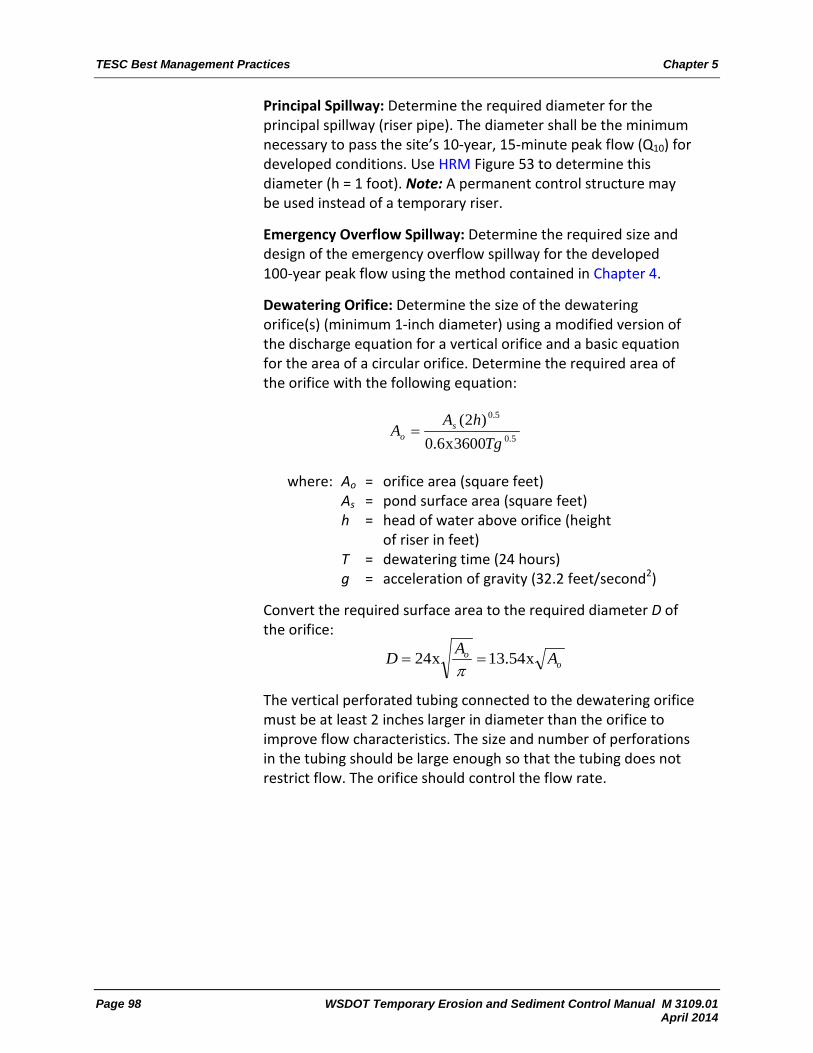
TESC Best Management Practices Chapter 5
Page 98 WSDOT Temporary Erosion and Sediment Control Manual M 3109.01 April 2014
Principal Spillway: Determine the required diameter for the principal spillway (riser pipe). The diameter shall be the minimum necessary to pass the site’s 10-year, 15-minute peak flow (Q10) for developed conditions. Use HRM Figure 53 to determine this diameter (h = 1 foot). Note: A permanent control structure may be used instead of a temporary riser.
Emergency Overflow Spillway: Determine the required size and design of the emergency overflow spillway for the developed 100-year peak flow using the method contained in Chapter 4.
Dewatering Orifice: Determine the size of the dewatering orifice(s) (minimum 1-inch diameter) using a modified version of the discharge equation for a vertical orifice and a basic equation for the area of a circular orifice. Determine the required area of the orifice with the following equation:
5.0
5.0
3600x6.0)2(Tg
hAA s
o =
where: Ao = orifice area (square feet) As = pond surface area (square feet) h = head of water above orifice (height
of riser in feet) T = dewatering time (24 hours) g = acceleration of gravity (32.2 feet/second2)
Convert the required surface area to the required diameter D of the orifice:
The vertical perforated tubing connected to the dewatering orifice must be at least 2 inches larger in diameter than the orifice to improve flow characteristics. The size and number of perforations in the tubing should be large enough so that the tubing does not restrict flow. The orifice should control the flow rate.
oo AAD x54.13x24 ==π
Chapter 5 TESC Best Management Practices
WSDOT Temporary Erosion and Sediment Control Manual M 3109.01 Page 99 April 2014
Additional Design Specifications:
The pond shall be divided into two roughly equal volume cells by a permeable divider that will reduce turbulence while allowing movement of water between cells. The divider shall be at least one-half the height of the riser and a minimum of 1 foot below the top of the riser. Wire-backed, 2- to 3-foot-high, extra-strength filter fabric supported by treated 4x4s can be used as a divider. If the pond is more than 6 feet deep, a different mechanism must be proposed. A riprap embankment is one acceptable method of separation for deeper ponds. Other designs that satisfy the intent of this provision are allowed as long as the divider is permeable, structurally sound, and designed to prevent erosion under or around the barrier.
To aid in determining sediment depth, 1-foot intervals shall be prominently marked on the riser.
If an embankment of more than 6 feet is proposed, the pond must comply with the criteria contained in HRM BMP FC.03 regarding dam safety for detention BMPs.
The most common structural failure of sedimentation basins is caused by piping. Piping refers to: (1) water seeping through fine-grained soil, eroding the soil grain by grain and forming pipes or tunnels, and (2) water under pressure flowing upward through a granular soil with a head of sufficient magnitude to cause soil grains to lose contact and capability for support.
The most critical construction sequences to prevent piping will be:
Tight connections between riser and barrel and other pipe connections.
Adequate anchoring of riser. Proper soil compaction of the embankment and riser footing. Proper construction of antiseep devices.
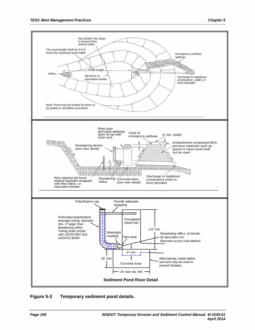
TESC Best Management Practices Chapter 5
Page 100 WSDOT Temporary Erosion and Sediment Control Manual M 3109.01 April 2014
Proper construction of antiseep devices.
Figure 5-3 Temporary sediment pond details.
Riser pipe(principal spillway)open at top withtrash rackper Fig 4.4.4E
Dewatering device(see riser detail)
Wire-backed silt fencestaked haybales wrappedwith filter fabric, orequivalent divider
Dewateringorifice
Concrete base(see riser detail)
Discharge to stabilizedconveyance outlet orlevel spreader
Embankment compacted 95%pervious materials such asgravel or clean sand shallnot be used
6' min. WidthCrest ofemergency spillway
Key divider into slopeto prevent flowaround sides
The pond length shall be 3 to 6times the maximum pond width Emergency overflow
spillway
Discharge to stabilizedconveyance, outlet, orlevel spreader
Note: Pond may be formed by berm orby partial or complete excavation
InflowPond length
Silt fence orequivalent divider
Riser pipe
Perforated polyethylenedrainage tubing, diametermin. 2" larger thandewatering orifice.Tubing shall comply with ASTM F667 and AASHTO M294
Polyethylene cap Provide adequatestrapping
Dewatering orifice, schedule,40 steel stub min.Diameter as per calculations
Alternatively, metal stakesand wire may be used toprevent flotation
2X riser dia. Min.
Concrete base
Corrugatedmetal riser
Watertightcoupling
18" min.
6" min.
Tack weld
3.5" min.
Sediment Pond Riser Detail

Chapter 5 TESC Best Management Practices
WSDOT Temporary Erosion and Sediment Control Manual M 3109.01 Page 101 April 2014
5-1.1.45 TIRE WASH
Standard Specification 8-01.3(7) – Stabilized Construction Entrance
Purpose
A tire wash is used when a stabilized construction entrance does not prevent sediment from being tracked onto off-site pavement. An effective tire wash will prevent sediment track-out.
Additional Information
A tire wash should be included in the contract if grading equipment will use the roadway to haul materials off-site. If a tire wash is not included in the contract, one may become required if track-out cannot be prevented with a stabilized entrance.
Effective function requires participation by and communication with vehicle drivers to ensure all vehicles leaving the site pass through the tire wash at a slow enough speed to remove sediment (usually about 30–45 seconds depending on soil type).
Washwater shall be discharged to a separate on-site treatment system, such as closed-loop recirculation or upland application, or discharged to a sanitary sewer, if allowed by a local sewer district permit. Upland application will not be allowed if oil sheen or other contaminants are present in the washwater. Local jurisdictions may require a tire wash as a permit condition.
Effective tire washes will include the following features:
Stabilized approach (paved, quarry spall pad, or rumble plates) that is maintained clear of excess soil.
Appropriately sized wash deck based on soil type (minimum of one complete tire revolution; more revolutions will be required for more cohesive soil types).
Multiple angled spray patterns (must reach all tires and undercarriage).
High-volume, moderate-pressure spray.
Rinse water maintained at reasonable clarity.
Collection of overspray and drip out.
Stabilized egress (paved, quarry spall pad, or rumble plates) that is maintained clear of excess soil.

TESC Best Management Practices Chapter 5
Page 102 WSDOT Temporary Erosion and Sediment Control Manual M 3109.01 April 2014
5-1.1.46 TOPSOILING
Standard Specifications 8-02.3(4) – Topsoil 9-14.1 – Soil
Purpose
Topsoil creates a suitable growth medium for vegetation and permanent site stabilization. Topsoil, often called tilth, includes the top layers of soil and the organic material. Native topsoil often contains mycorrhizal bacteria that are acclimated to the site and will provide optimum growing conditions. Amending or importing topsoil promotes vegetation establishment in areas with poor topsoil. While topsoiling itself is not a stabilizing cover, it is an important part of achieving a vegetated cover. Topsoiling should be used in conjunction with other BMPs such as seeding, mulching, or sodding.
Additional Information
Restore, to the maximum extent practical, native soils disturbed during construction. Use on-site native topsoil, incorporate amendments, or import blended topsoil.
Ensure landscaped areas contain healthy topsoil with 8% to 15% organic matter so the need for fertilizer is minimized.
Preserve existing soil systems in undisturbed and uncompacted conditions whenever feasible.
Be aware that topsoil may contain seeds from invasive species that will cause plant establishment problems.
5-1.1.47 VEGETATED STRIPS
No WSDOT Standard Specification exists, so a Special Provision must be written.
Purpose
Vegetated strips are used to reduce the transport of sediment from a construction site by providing a physical barrier that reduces runoff velocities.
Additional Information
Vegetated strips may be used downslope of all disturbed areas. The strips are not intended to treat concentrated flows, nor are they intended to treat substantial amounts of overland flow. Any concentrated flows must be conveyed through the drainage system to a sediment pond or a comparable BMP. The only circumstance in which overland sheet flow can be treated solely by a strip, rather than by a sediment pond or comparable BMP, is when the criteria shown in Table 5-5 are met.

Chapter 5 TESC Best Management Practices
WSDOT Temporary Erosion and Sediment Control Manual M 3109.01 Page 103 April 2014
Ideally, vegetated strips consist of undisturbed native growth with a well-developed soil that allows for infiltration of runoff. When this is not possible, soil amendments are needed to establish vegetation and increase the ability of the soil to hold water.
Table 5-5 Vegetated strips.
Average Slope Slope Percent Flowpath Length
1.5H:1V or less 67% or less 100 feet
2H:1V or less 50% or less 115 feet
4H:1V or less 25% or less 150 feet
6H:1V or less 16.7% or less 200 feet
10H:1V or less 10% or less 250 feet
5-1.1.48 VEGETATIVE DISPERSION AND INFILTRATION
Standard Specification 8-01.3(1)D – Dispersion/Infiltration
Purpose
Vegetative dispersion and infiltration are used to disperse and infiltrate turbid stormwater or dewatering to prevent a discharge to surface waters.
Additional Information
Never use ditched stream channels and other sensitive areas for dispersion or infiltration activities. Do not use this BMP in areas with high groundwater. Use roadside ditches only when they can reasonably be expected to prevent runoff or fine sediments from reaching receiving streams based on field observations and soils information. Note: Consult WSDOT maintenance personnel, who are an excellent resource, with many years of observations about flow under wet weather conditions.
Always obtain prior written authorization from adjacent landowners before dispersing water onto adjacent non-WSDOT properties.
Maximize infiltration by spreading water over the largest possible area, discharging water at a slow and constant rate, and using vegetated areas whenever possible. Forested areas have the potential to hold and infiltrate more water than shrub or grasslands. Disperse flows so as not to cause erosion during infiltration. Install pumps, distribution manifold, perforated pipe, spinklers, wattles, compost socks, level spreaders, or other BMPs where necessary to enhance the effectiveness of the dispersion and infiltration areas. If an area becomes saturated, give it a rest period and try again later.

TESC Best Management Practices Chapter 5
Page 104 WSDOT Temporary Erosion and Sediment Control Manual M 3109.01 April 2014
Label dispersion and infiltration areas on the TESC plan sheets as any other BMP would be. Control discharge rates to infiltration areas to encourage complete infiltration and avoid discharges whenever possible. If discharges occur, sample runoff at the discharge point in accordance with the permit conditions. Stop discharging water to the infiltration area if standing water or erosion occurs.
Inspect infiltration areas daily during infiltration activity to verify that the areas continue to infiltrate and function as intended. If deposited sediment is present after infiltration, stabilize the sediment or remove it to prevent its release to surface waters.
Silt and clay deposits reduce infiltration capacity. Upslope erosion and sediment control BMPs, especially sediment traps and ponds, are essential to ensure consistent performance of infiltration facilities. Always provide some pretreatment to remove as much sediment as possible prior to infiltration.
5-1.1.49 WATER PUMPS
No Standard Specification exists, so a Special Provision must be written.
Purpose
Water pumps are used to manage collected or continual sources of surface or groundwater.
Additional Information
Select pumps based on the job that needs to be done. There are numerous types and sizes of pumps available. The most common pumps used on construction sites include the following:
Submersible pumps are most commonly used to remove water from confined areas such as ponds.
Centrifugal pumps can be very high-powered, but they should be used only when water is fairly clear.
Trash pumps are rugged and dependable in situations where there are suspended solids. This is the most common pump used for dewatering.
Diaphragm pumps work well for slow seepage applications where centrifugal pumps would lose their prime or when the material is muddy or has suspended solids.