temporary document - ieee-sa - working...
TRANSCRIPT

INTERNATIONAL TELECOMMUNICATION UNION STUDY GROUP 5TELECOMMUNICATIONSTANDARDIZATION SECTORSTUDY PERIOD 2009-2012
TD 511rev1 (GEN/5)English only
Original: EnglishQuestion(s): 21/5 Geneva, 23 November - 1 December 2010
TEMPORARY DOCUMENT
Source: Rapporteur Q21/5
Title: Revised draft new Recommendation ITU-T L.adapter Phase2 prepared for discussion in Geneva
Draft new Recommendation ITU-T L.adapter Phase2
Universal common power supply for ICT devices that require an external power adapter
Keith and Ahmed Comment : document structure to be defined after, separate or merged with existing L.1000
Summary
This recommendation provides high level requirements for a universal common power supply solution for ICT devices with external power voltage adapter from AC mains to their low voltage input.
The aim is to reduce the number of power adapters and chargers produced and recycled by widening their application to more devices and by increasing their lifetime.
The solution also aims to reduce energy consumption. The longer life cycle and possibility of avoiding device duplication reduces the demand on raw materials and waste.
The universal common power supply solution is designed to serve the great majority of ICT powered by AC/DC adapters and mobile or portable terminals accepting universal common power supply compliant with L.1000.
Contact: Didier MarquetFrance Telecom OrangeFrance
Tel: +33 1 45 29 52 51Fax:Email [email protected]
Contact: Zhang XiaMIITChina
Tel: +86 10 68094171Fax: +86 10 68011404Email [email protected]
Attention: This is not a publication made available to the public, but an internal ITU-T Document intended only for use by the Member States of ITU, by ITU-T Sector Members and Associates, and their respective staff and collaborators in their ITU related work. It shall not be made available to, and used by, any other persons or entities without the prior written consent of ITU-T.

- 2 -TD 511rev1 (GEN/5)
China comment : Explain the progressive introduction in short time (2 years, …) in summary or introductionThis recommendation is the second study phase of L.1000 and to extend the universal power solution to many more ICT devices than mobile terminals.
An introduction to the Home/Office DC network based on the same power interface is proposed which enables or simplifies the functionalities of power back-up, power management and renewable energy use. This is in line with the green DC building initiative [B-4].
Keywords
Power adapter, charger, energy-efficiency, ecodesign, universal charger solution, common power adapter
Introduction
This Recommendation addresses the issue of a universal common power supply for ICT devices using an external AC mains adapter or charger. It includes a compatible solution with the L.1000 universal charger solution for mobile terminals.
This Recommendation also takes in to consideration energy efficiency, emissions reduction and the transport and use of scarce and raw materials. It has been estimated (see appendix xxx) that the widespread adoption of a universal common power supply solution for ICT devices will result in a xxx per cent reduction in standby energy consumption and approximately xxxx million tons of greenhouse gas emissions each year. The universal common power supply solution will be more convenient and simpler to use for the consumer who will be able to power or charge their home or portable ICT terminals, including mobile phones, from any available power plug and use the same power adapter for many future ICT devices, thus eliminating up to xxxxxx tons of duplicate power adapters and chargers. The longer term benefits of introducing a Universal common power supply solution will be realized once devices can be sold with no charger or power adaptor in the box thereby eliminating the need for another new unit.
Contribution on gain assessment required There is a TD from Didier with the calculation Tools and assumption, and market statistics.
It is noted that the environmental impact of any universal common power supply solution should be considered over the entire life-cycle and that the transition towards a universal solution does not aim to replace existing solutions immediately; this is because there is an estimated xxxx billion of them currently in use.
This Recommendation was drafted with support from and in consideration of activity in other SDOs and organizations.
This Recommendation is designed to ensure the universal common power supply solution operates within recognized current and voltage safety parameters by adopting existing terminal technologies from a wide range of Home and portable ICT such as mobile phones, portable computers, media players, all using external extra low voltage adapters from the AC mains.

- 3 -TD 511rev1 (GEN/5)
The main differences with L1000 universal charger for mobile phone, are the voltage, power range and the parameter setting functionalities associated.
The interface can be used in several arrangements: single adapter, multi-outputs adapter, very low voltage DC network
Options may be considered:
Interface to external or integrated back-up, direct input for renewable energy, output shut down option to reduce power consumption of unused ICT. Is it necessary in step 2 core part, or do we wait to know if we need to standardize this in further complementary parts.
IEEE UPAMD 3springs to mind
1 Scope
This Recommendation describes the general requirements for a universal common power supply solution for a wide range of ICT devices that require AC/DC mains adapters (e.g. home gateways, set-top box, portable computers, mobile phones, media recorders/players, computer monitors, picture display.
Keith comment : this recommendation address ICT with power requirement wider than USB
This Recommendation includes basic configurations and general requirements for the universal common power supply and its interface, energy efficiency, safety, electromagnetic compatibility, resistibility, and eco-environmental specifications.
This recommendation address ICTs with power requirement wider than USB, and longer power cable.
Note : USB cables are limited to 2 meters in most of the case, which does not allow a DC power distribution
2 References
The following ITU-T Recommendations and other references contain provisions, which, through reference in this text, constitute provisions of this Recommendation. At the time of publication, the editions indicated were valid. All Recommendations and other references are subject to revision; users of this Recommendation are therefore encouraged to investigate the possibility of applying the most recent edition of the Recommendations and other references listed below. A list of the currently valid ITU-T Recommendations is regularly published.
The reference to a document within this Recommendation does not give it, as a stand-alone document, the status of a Recommendation.
[1] ITU-T Recommendation K.21 Resistibility of telecommunication equipment installed in customer premises to overvoltages and overcurrents
[2] ITU-T Recommendation K.74 EMC resistibility and safety requirements for home network devices
[3] ITU-T Recommendation K.66 Protection of customer premises from overvoltages
[4] CISPR Publication 22 Information technology equipment - Radio disturbance characteristics - Limits and methods of measurement
[5] CISPR Publication 24 Information technology equipment - Immunity characteristics - Limits and methods of measurement

- 4 -TD 511rev1 (GEN/5)
[6] IEC 60950-1 Information technology equipment — Safety —Part 1: General requirements
[7] ISO 14040 Environmental management - Life cycle assessment - Principles and framework
[8] ISO 14044 Environmental management - Life cycle assessment - Requirements and guideline
[9] IEEE 1680: Environmental Assessment of Personal Computer Products, Including Laptop Personal Computers, Desktop Personal Computers, and Personal Computer Monitors
[10] IEC 62430 Environmentally conscious design for electrical and electronic products
[12] IEC 60038: "IEC standard voltage".
[13] IEC EN61204 series for DC power supply
[15] IEC 62301 Ed 1.0: Measurement of standby power
[16] IEC62542: Standardisation of environmental aspects - Glossary of terms.
If required :
[17] IEEE 1725 Standard For Rechargeable Batteries for Cellular Telephones
[18] IEEE 16725 Standard For Rechargeable Batteries for computer
[19 if published before this recommendation] IEEE 18725 Standard For Rechargeable Batteries for CamcorderCellular Telephones
Comment : IEEE reference To be checked
3 Definitions
3.1 Terms defined in this Recommendation
This Recommendation defines the following terms:
3.1.1 Universal Charger Solution: overall initiative that defines the charger solution for different mobile terminals and ICT devices. It is a part of the common power supply solution
3.1.2 Power Adapter: The equipment that converts mains AC power voltage at the input to low DC power voltage at the output, or the equipment which transfers DC power supply e.g. car voltage to another low voltage of DC power output.
3.1.3 Detachable Cable: A detachable cable connects the power adapter to the mobile terminal or other ICT device for powering through 2 connectors, one on the charger side and one on the mobile terminal or ICT device side.
3.1.4 Charger: A common term used to describe the power adapter for an ICT device used to apply power to the battery charge input.
3.1.5 Power Adapter: power adapter of mains voltage to the input low voltage of ICT device (generally in DC).
3.1.6 Common Power Supply Solution: Any solution that powers ICT (Mains power adapter, renewable source) which has a power interface compliant to this standard which is accepted by a wide range of ICT devices, and is able to supply one or more of them at the same time
Terms related to environment aspects shall respect the glossary of terms of IEC62542 [16]

- 5 -TD 511rev1 (GEN/5)
4 Abbreviations and acronyms
This Recommendation uses the following abbreviations and acronyms:
AC Alternating Current
PA Power Adapter
DC Direct Current
GHG Green House Gas Emission
ICT Information Communication Technology
LVDC Low Voltage Direct Current
OMTP Open Mobile Terminal Platform
PDA Personal Digital Assistant
USB Universal Serial Bus
CPS Common Power Supply
UCPS Universal Common Power Supply
SCCP Short Chain Chlorinated Paraffins
5 Basic Configuration of Universal Common Power Supply solution
The universal common power supply solution may consist of three elements:
1) common power supply (CPS) e.g. mains power adapter( PA) of an ICT device or renewable energy power supply (e.g. solar, wind) or ICT power output equipped with interface A
2) one or more detachable cables with either interface A and B
3) one or more ICT devices
Interface A and B are defined by electrical and mechanical features.
Note 1: Further study is needed to specify more details (e.g. logical, functional or physical).
Note 2: connectors A and B should be different to avoid confusion. As already many ICT exist with different connectors and voltage/current caracteristics, at least the first standard interface is the interface A at the output of the CPS.

- 6 -TD 511rev1 (GEN/5)
Figure 1 – One possible basic configuration of three elements for Universal Common Power Supply
Annex B gives a first phase solution of a single or multi-output UCPS replacing AC/DC adapter
Annex A defines different possible configurations
Note : Examples of Some possible additionnal options of UCPS are shown in Annex ppendix xxxx (:back-up, DC network, renewable energy interface.)

- 7 -TD 511rev1 (GEN/5)
6 General requirements
Any device that uses an External Power Supply and that is inside the power range is within the scope of the UCPS. The devices could be in two distinctions:
Category A - Device that requires a permanent connection to an electrical supply and has no internal battery for normal operation (e.g. display, small network element common to several users)
A non exhaustive list of examples can be: Media player/recorder (PVR/DVR) boxes, media tanks, set top boxes, portable PC, netbooks, handbooks, portable tablets, digital cameras, home networking devices, mobile terminal accessories, DECT/IP phones, portable TVs, PC accessories, printers/scanners, rechargeable battery chargers etc.
Category B - Device that requires occasional connection to an electrical supply to recharge an internal battery but can operate normally from the internal battery(s).
The category A can show several power consumption mode depending on active device and standby functions. There is a maximum load power of the device. There is also an inrush power when the equipment is connected to the UCPS.
In addition, the category B will show another power consumption for recharging battery. This power can be higher than the maximum load power of the device e.g. 30W for the full load computer activity + 50W for battery charging. The interface A should be able to supply this maximum power.
Within the portable device category, there is a wide range of options covering single or multi cell battery (generally of NiMH or Lithium technology family), low or high voltage / current requirements. Additionally this category covers low end and ultra low end tier phones or ICT for developing markets, such as base station community power, using renewable energy, and batteries in charging huts.
6.11 Power adapter interface
The power adapter is required to provide an output DC voltage and DC current.
Comment Xia : put also into the scope wireless or contactless energy (WPC Wireless Power Consortium is defining this industry standard for pad, long distance witricity ?)
Comment Eunah : consider availability of figures
Comment Ian : one pad can replaces several mobile chargers. Step one is with added cover with the coil, second step is with coil in the battery). No load is already 5 stars 0,01W, 70% efficiency ?
Comment Didier : to check the ICT covered by wireless charger is it more convenient than connectors? impact on material and recycling use ?Please contribute
The voltage and current are defined with a wide range compliant to the wider range that is possible across ICT devices.
In further step and future study, we should try to get standard voltage for a wide majority of ICT (e.g. 12 V) and also cover .
Tthe wireless powering or charging technology is for further study.
Any device that uses an External Power Supply and that is inside the power range is in scope.
The following scope to be reviewed in details
Within this there are distinctions:

- 8 -TD 511rev1 (GEN/5)
A - Device that requires a permanent connection to an electrical supply and has no internal battery for normal operation (e.g. display, small network element common to several users)
B - Devices that requires occasional connection to an electrical supply to recharge an internal battery but can operate normally from the internal battery(s)
C - Small network element common to several users
A non exhaustive list of examples can be:
Eunah : classify each example in category A and B
Media player/recorder (PVR/DVR) boxes, media tanks, set top boxes, portable PC, netbooks or handbook or portable tablet, digital cameras, home networking devices, mobile terminal accessories, DECT/IP phones, portable TVs, PC accessories, printers/scanners, rechargeable battery chargers etc.
Within the portable device class, there is a wide range of options covering single or multi cell battery, low or high voltage / current requirements.
Additionally the scope covers low end and ultra low end tier phones or ICT for developing markets, such as base station community power, using renewable energy, and batteries in charging huts.
6.1.1 Power ranges :
The power range on interface A is complementary to L.1000 for mobile phone, from 10 W to 1300 W.
Note 1: IEEE UPAMD [5] has defined 130W in [B xxxx]These values are not strictly defined but better to stay lower than 1300W to stay in class 2 cabling (standard to be checked by expert, IEEE UPAMD is looking at 10-130W).
Didier : Check (safety class IEC 60 950-x ?) class issue above 100W maybe in Emerge Alliance
Note L.1000 for USB output (e.g. for mobile phone) : defines a maximum of 7,5 W
The UCPS should be protected against over current. The limit are defined in § 2.5 of IEC 60 950-1 [6].
Didier : do we need to split in several power ranges and how, we have just an example in the following : need more contribution Xia: There is a contribution from China C169
UCPS1 can power range 1:
- Power up to 30W
- Voltage from 5 to 20 V
- Maximum current 2 A
- Which covers from fixed phone to set-top box (some set-top box use AC220V) and PC, excluding quick charge.
- Generally one or 2 outputs at maximum
Alternative proposal from China C169:

- 9 -TD 511rev1 (GEN/5)
Rationale : It is safer to fit voltage to power and to avoid voltage overlap and so user mistakes:
- Power up to 30W- Output voltage from 5 to 12V- Maximum current 3A- Output rated current 2.5A- Which covers from digital camera, video, cordless telephone, ADSL, Home gateway and so on.- Generally one or two outputs at maximum
Note 1: A range of current till 2 A is in HGI document [Bxxx]
Note 2: The lower voltage limit 5V ensures compatibility with L.1000 standard, by default if ICT device is not identified when plugged, for safety reason, the voltage and current limited to values defined in L.1000 for mobile terminals.
Comment Xia, Ian : be very careful of the cost and complexity for intelligent charger able to adapt voltage and current. Maybe difficult in first phase.
UCPS 2 for power range 2:
- power up to 1300W
(to be checked if class 2 limits to 100W or not)
- interface A voltage from 5 to 30 V
- maximum current 6 A
Xia: There is a contribution from China
Alternative proposal from China C169:
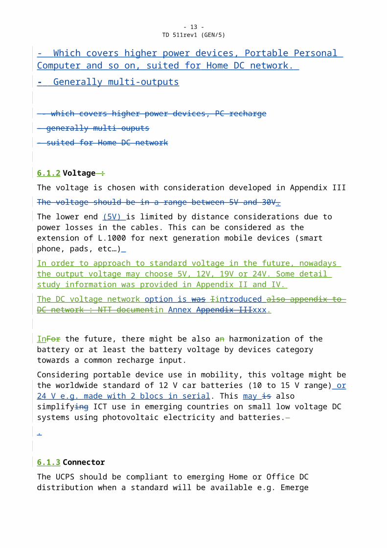
- Power up to 130W- Output voltage from 12 to 24V- Maximum current 6A- Output rated current 5.5A- Which covers higher power devices, Portable Personal Computer and so on, suited for Home DC network. - Generally multi-outputs
- which covers higher power devices, PC recharge
- generally multi-ouputs

- 10 -TD 511rev1 (GEN/5)
- suited for Home DC network
6.1.2 Voltage :
The voltage is chosen with consideration developed in Appendix III
The voltage should be in a range between 5V and 30V.
The lower end (5V) is limited by distance considerations due to power losses in the cables. This can be considered as the extension of L.1000 for next generation mobile devices (smart phone, pads, etc…)
In order to approach to standard voltage in the future, nowadays the output voltage may choose 5V, 12V, 19V or 24V. Some detail study information was provided in Appendix II and IV.
The DC voltage network option is was Iintroduced also appendix to DC network : NTT documentin Annex Appendix IIIxxx.
InFor the future, there might be also an harmonization of the battery or at least the battery voltage by devices category towards a common recharge input.
Considering portable device use in mobility, this voltage might be the worldwide standard of 12 V car batteries (10 to 15 V range) or 24 V e.g. made with 2 blocs in serial. This may is also simplifying ICT use in emerging countries on small low voltage DC systems using photovoltaic electricity and batteries.
.
6.1.3 Connector
The UCPS should be compliant to emerging Home or Office DC distribution when a standard will be available e.g. Emerge Alliance [B-xxxx] proposing 24V and standard connector for interface A.
The UCPS should be compliant to emerging standard for ICT universal DC connector for interface B when available e.g IEEE P1823 [B-xxxx].
The most often used connectors on the ICT devices of higher power than phones are now is barrels. Some detail study information arewas provided in Appendix IV.
Appendix xxx proposed the 30 pins connector option (USA contrib. C194) : TO BE DISCUSSED
Ripple and EMC
This DC Power supply shall be compliant with standard ??? (international)
EN61204 [13] and ETSI EN 301 489-34 To be checked in detail by experts

- 11 -TD 511rev1 (GEN/5)
6.2 Energy efficiency requirements
6.2.1 No load power consumption
The no-load power consumption of the UCPS adapter should be low as is practicable. It is expected that the industry aims for a figure as close to zero as possible. If practicable the UCPS should indicate to the customer its no load condition.
When used to recharge devices, it is expected that the industry aims for the UCPS to enter a shut down mode to minimise power consumption either when the unit is removed from the supply or when the battery is fully charged, thereby ensuring significant energy savings.
6.2.2 Power efficiency with load
It is expected that the industry aims to minimise the power dissipated in the UCPS whilst powering the load device.
6.2.3 Solar power for chargers and mobile phone and related ICT devices
Solar-powered mobile terminals could reach about two billion people across the globe who do not have access to electricity. Solar power has the advantage of being more sustainable and better for the environment than the electricity grid which currently uses fossil fuel in its mix of energy sources.
It is therefore recommended that UCPS and portable ICT devices be designed to make maximum use of available renewable energy
Note: The renewable energy sources can be of considerable interest for the requirements of some developing countries e.g. solar photovoltaic, wind power.
As an example, UCPS interfaces would need to be designed so that they do not stress ICT device by providing too much current when solar input is also taking place. High temperature stresses on the ICT device caused by sun exposure should also be avoided.
Note: In the future, this Recommendation may be updated to use additional sources based on any form of energy harvesting.
Note: a set of requirement for a Solar handset (and charger) has been proposed in GSMA project [B-xxxx] To be Checked if we need to put example in this document
6.3 Safety requirements
The UCPS must be a Limited Power source in accordance with IEC60950-1 clause 2.5, and comply with the safety requirements of IEC60950-1, ITU-T Recommendation K.74 and of the country where it is sold and used.
The UCPS is required to have a safety circuit in order to prevent any occurrence of heat generation, leakage of electricity, fire ignition, etc in fault condition.
The UCPS and detachable cable are required not to harm the human body by heat generation, leakage of electricity, fire ignition, etc during normal/abnormal usage.
The UCPS and detachable cable are required to have sufficient endurance so as not to be easily damaged during normal use. The detachable cable is required to comply with the electrical current specification of the UCPS.

- 12 -TD 511rev1 (GEN/5)
Safety aspects of different possible combinations of UCPS, detachable cables and load units should be addressed.
Considering the ICT device scope, the UCPS shall be compliant with chargers requirements for battery recharge safety included in IEEE 1625[17 ], IEEE 1725 [ [18], IEEE 1825 [ [19 if published before this recommendation] to be checked with expert.
6.4 EMC requirements
UCPS , in accordance with the definition of this Recommendation, should comply with emission requirements described in CISPR Publication 22. They should also comply with immunity requirement described in CISPR Publication 24 and ITU-T Recommendation K.74 (?) . ETSI EN 301 489-34 should apply for UCPS with USB standard A output port.
See China Contribution C170
6.5 Resistibility requirements
The resistibility requirements in Recommendation K.21 and K.66 should be applied
6.6 Eco-Environmental specification
Environmental criteria are gaining importance in all aspects of electronic design.
Life Cycle Assessment (LCA) should be established in compliance with ISO 14040 [7] and ISO 14044 [8].
The UCPS should be compliant with IEC 62430 [10] Environmentally conscious design for electrical and electronic products.
6.6.1 EcodesignEcodesign has increased in importance due to full life cycle environmental impact considerations (GHG emissions and waste material). Eco certification is currently under development but there is currently no specific ecodesign for power supplies, therefore some basic principles are contained in Appendix VI and in IEEE 1680 [9].
6.6.1.1 Eco design Criteria for Electronics
Environmental criteria for electronic goods key domain areas cover eco materials, reuse, recycling and design considerations.
It is recommended that due consideration is given to the environmental performance categories that are listed below:
a) Environmentally sensitive materials:
Comply with regulations, which restrict cadmium, mercury, lead, hexavalent chromium, and selected brominated flame retardants.
Eliminate SCCP Short Chain Chlorinated Paraffins used as flame retardants and plasticizers)
Eliminate paints and coatings that are incompatible with recycling or reuse.
For recycling purposes, identify environmentally sensitive components and hazardous materials.
Comment : check if we need more for battery option, recycling of heavy metal, (ROHS ref ?)
- 13 -TD 511rev1 (GEN/5)
b) Packaging:
The ICT sector as a whole will be reviewing various improvements concerning packaging to decrease waste and landfill.
Recyclable packaging materials
Separable packing materials
Packaging 90 percent recyclable and plastics labelled
Design for End of Life
Declaration of recycled content.
6.6.2 Lifetime
The expected lifetime of the element of a UCPS solution should be designed so that it is of sufficient duration to deliver waste reduction through extended normal use.
The initial value for the lifetime parameter should be set at 5 years to match the ecodesign objective of the UCPS solution for ICT including electronics, enclosure, cables and plugs. Further studies are required to analyze the effects of various parameters e.g. temperature, use, on this value.
Product longevity / life cycle extension topics are covered below:
Availability of additional longer life warranty
Spare or replacement parts should be made available for five years as well as information on how to obtain the parts.

- 14 -TD 511rev1 (GEN/5)
Annex A
Universal Common Power Supply Solution progressive approach
This recommendation addresses the majority of ICT devices.
Some fora or initiatives already consider the extension of this solution to electrical household devices not connected to any telecom network.
The introduction of Low Voltage DC home networks could be one of the solutions to avoid the need for many power adapters or chargers.
All of which introduces the issue of self recognition and configuration of the power adapter and charger in addition to the connecting issue, whether it is manual or automatic self configuration.
These next steps should also address the issue of standard voltage and standard power ICT connector.
It is seen as very useful in the first instance to define an immediate solution applicable to existing ICT devices and power supplies even if it does not cover the entire spectrum of solutions, and then progress to a solution that is more optimized and open to the evolution towards more generalizsed and more standard solutions.
In phase one the recommendation is to adopt a 3 part solution replacing the existing power adapter with captive cord so that maximum use and flexibility of the UCPS can be achieved.
This also requires a detachable cable with active function within the three part solution. The specific active cables to an ICT device reduces the interoperability to a degree but still achieves the anticipated benefits of a Universal common power supply being adopted across a wider range of ICT devices.
Configuration 1 :
Adjustable UCPS and detachable cable with setting information
The output of the UCPS is a standard connector.
In order to cover a wider range of voltage/current it may be necessary to specify a UCPS with adjustable power output levels in voltage and current that are controlled by an active cable with passive information or with a smart controller sending a protocol that sets the correct output in U and I or by setting on the UCPS (see annex B for details).
Configuration 21 :
Fixed voltage power supply (e.g. 12V or 24V) and active detachable cable converting the voltage
The output of the UCPS is a standard connector.
- 15 -TD 511rev1 (GEN/5)
The active cable can include a power converter giving the required voltage and eventual current limitation.
Configuration 2 :
Adjustable UCPS and detachable cable with setting information
The output of the UCPS is a standard connector.
In order to cover a wider range of voltage/current it may be necessary to specify a UCPS with adjustable power output levels in voltage and current that are controlled by an active cable with passive information or with a smart controller sending a protocol that sets the correct output in U and I.
Configuration 3:
Standard voltage and connector at the ICT input
The output of the UCPS is a standard connector.
A standard interface has been defined for ICT input, which allows simplifying the UCPS to a single voltage interface and the output connector to one standard type covering the full power range.
Note: this leads also to adaptation inside the portable equipment for this single voltage to match the battery charging voltage requirement.
Comment required, contribution to check if we cover all the possible configuration and if there is possibility to simplify
Zhang: checked, and support these three configurations.

- 16 -TD 511rev1 (GEN/5)
Annex B
UCPS solution with detachable cable and UI setting capability
This annex provides the solution of configuration 1 in annex A. The solution of other configurations is for further study.
B.1 Basic configuration
This configuration is the configuration 1 in annex A
The basic configuration of a universal common power supply solution for ICT devices consists of:
1) power adapter (power supply or charger of the ICT) with UI setting capability
2) detachable cable
3) ICT device with UI setting information
Mains ---AC/DC UCPS with UI setting capability standard output connector----detachable cable with setting----ICT device with interface B standardized or notUI information
Drawing to be done, when we agree on this configuration
Figure B.1 - Basic elements of UCPS solution
The use of a three element configuration can expand the application of a common power adapter.
Firstly, it unifies the power adapter and charger output port in one type which enables different types of ICT devices to share one type of UCPS.
Secondly, the application of the UCPS can be expanded to many ICT of different type through the setting information for output voltage and current of the power adapter(PA), inside the cable (UI setting detachable cable) or by a selector on the UCPS.
Open to discussion : starting by the 2 proposed options for UI setting.
It also contributes to the reduction of e-waste, environmental protection, resource conservation and cost reduction.
B.2 UCPS solution
The AC input of the power adapter should accept a range of AC nominal voltage between 100 and 240V and nominal frequency of 50Hz and 60 Hz.

- 17 -TD 511rev1 (GEN/5)
The common power adapter is required to provide an output DC voltage of 5.0 V to 1240 V (power range 1) or 12 to 24 V (power range 2).
Note : to be checked if we need more than 20V
The precision of voltage setting must be +/- 5%.
The UCPSA is required to provide at minimum an output current of 2 A on the full voltage range. The maximum current on one output is 5,5 A.
The output connector receptacle on the UCPS should be durable enough to match the lifetime to the UCPS, a good example of this is a ruggedized type.
The diameter/length of the detachable cable should be decided carefully in accordance with the maximum output current. The cable assembly voltage and power loss is lower than 3% (max drop across power pair from pin to pin) at 2 A and 2 m distance. See loss calculation in appendix II.
In the case of DC network (annex xxxxappendix V) between the UCPS and the powered ICT device, the overall losses including the detachable cable is at maximum of 5% at 5,5 A and 10 m distance. (See appendix II).
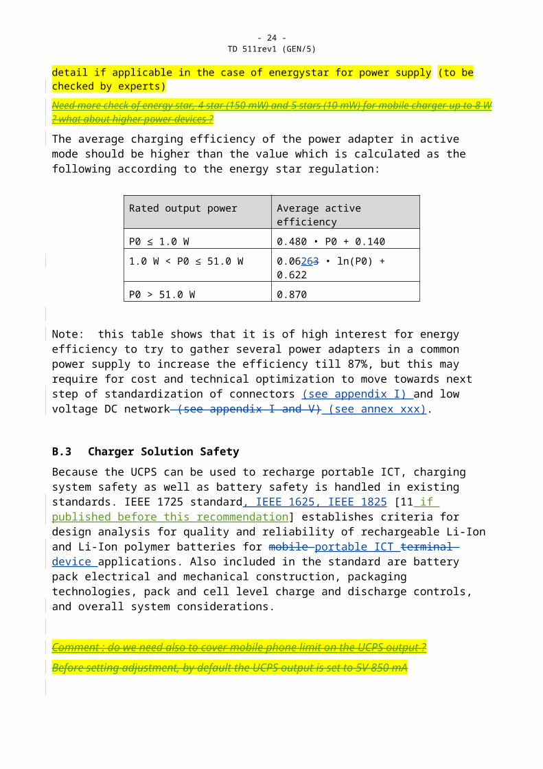
The no-load power consumption of the power adapter should be below 150mWxxxxx 0.3W according to the “energy star” regulation mandates for AC/DC external power supplies. A measurement method of standby power is proposed in IEC 62301 Ed 1.0 [15] to be verified in detail if applicable in the case of energystar for power supply (to be checked by experts)
Need more check of energy star, 4 star (150 mW) and 5 stars (10 mW) for mobile charger up to 8 W ? what about higher power devices ?
The average charging efficiency of the power adapter in active mode should be higher than the value which is calculated as the following according to the energy star regulation:
Rated output power Average active efficiency
P0 ≤ 1.0 W 0.480 • P0 + 0.140
1.0 W < P0 ≤ 51.0 W 0.06263 • ln(P0) + 0.622
P0 > 51.0 W 0.870
Note: this table shows that it is of high interest for energy efficiency to try to gather several power adapters in a common power supply to increase the efficiency till 87%, but this may require for cost and technical optimization to move towards next step of standardization of connectors (see appendix I) and low voltage DC network (see appendix I and V) (see annex xxx).
B.3 Charger Solution Safety
Because the UCPS can be used to recharge portable ICT, charging system safety as well as battery safety is handled in existing standards. IEEE 1725 standard, IEEE 1625, IEEE 1825 [11 if published before this recommendation] establishes criteria for design analysis for quality and reliability of rechargeable Li-Ion and Li-Ion polymer batteries for mobile portable ICT terminal device applications. Also included in the standard are battery pack electrical and mechanical construction, packaging technologies, pack and cell level charge and discharge controls, and overall system considerations.

- 18 -TD 511rev1 (GEN/5)
Comment : do we need also to cover mobile phone limit on the UCPS output ?
Before setting adjustment, by default the UCPS output is set to 5V 850 mA
B.4 Output Connector
The connector system shall have at least the following pins:
- 1 Pin or shell for power (called 0V)
- 1 Pins for power with variable voltage (+5V to +24V)
- 1 Pin for Ground(Optional)Comment : Ground/ cable screen connexion to be investigate
-
- To be investigate if we need signals :
- 1 Pin for signal 1(Optional)
- 1 Pin for signal 2(Optional)
Electrical characteristics for connectors
To be checked with expert
Each power pin is calibrated for 32A minimum for power range 1, and 64 A minimum and 30 V minimumfor power range 2.
The connectors are designed in accordance to the voltage range.
The voltage loss in the connector should be lower than 100 mV at 4 A.
The resistance of signal pin is lower than 1 ohm and they can accept also 30 V.
Pins are plated with metal avoiding corrosion.
Mechanical aspect for connectors
To be checked in detail :
The connector system can be a single connector, or a set of one power connector associated to a signal connector (e.g. 1 power jack + 1 USB A connector)
There is a solution to avoid mistake in position when inserting the connector
To obtain a good experience for the user the insertion and disconnection force is lower than 10 N, and disconnection force is high than 10N. aAnd there is a tolerance in the insertion angle in any direction allows. When connected, there should be a locking mechanism.
The precise connector standardization is out of the scope of this documentrecommendation.
Please refer to IEEE work [Biblio P1823] on the subject.
B.5. UI setting solution

- 19 -TD 511rev1 (GEN/5)
The setting can be done by 2 ways :
- By selector on the UCPS box;
- By If use the cable transfer voltage and current singles to UCPS, In the cable setting solution(use the detachable cable record and transfer UI information to UCPS), see B.6.
B.6 Cable setting solution
- By selector on the UCPS box
-
-
In the case of the cable setting solution, 2 possibilities are proposed:
- Passive analogical solution: voltage and current setting by resistance
- Digital solution: when powered, the cable gives sequence of ASCII characters with voltage and current information
TThe UCPS shall be able to read both if provided by the detachable cable on signal pins.
B.6.1 Passive solution example
It can be done by 2 resistances referenced to the power minus when 2 wire interface A or midpoint in case of 3 wires interface A (-12V, 0, + 12V):
R1 and R2 are resistances in the cable.
R1 on signal 1 gives information on the voltage (100 ohm/V).
e.g. UCPS provides current to signal 1 pin, under 1 mA, if 1,2 V is read, the resistance is 1 kohm, which means a requirement of 12V output).
Note : the power loss in resistor is 12 µW, which is much lower than no load power defined in Energy Star [ref xxxx]. The full power loss with reading circuitry should be lower than 1 mW.
R2 on signal 2 gives information on the voltage current (1 kohm/A).
e.g. under 1 mA, if 2 V is read and gives the information of a 2A required.
B.6.2 Digital solution example
As soon as the detachable is connected, an active device (e.g. a small controller able to run on the default voltage 5V present on the interface A) provides a serial message in ASCII code, including the voltage and current in clear,
e.g. the ASCII sequence of characters <UCPS>xx.xVy.yA</UCPS>,
where x and y are figure from “0” to ”9”.
Note 1: the XML syntax is proposed.

- 20 -TD 511rev1 (GEN/5)
Note 2: other information can be added later as it is easy in XML file (e.g. standard UIT-T reference L1001, …). They must never use the same header <UCPS>.
Note 3: In default mode the parameters of the serial port are set to clock = 9600bps, Parity = pair, 1start bit, 1 stop bit.
IBut it is recommended that the UCPS be able to auto-detect the parameters.
Note 4: the very common small CMOS microcontroller or equivalent logical circuitry can have very low consumption, of some mW or lower with standby mode, in this kind of application requiring very low processing power.

- 21 -TD 511rev1 (GEN/5)
Annex C Low voltage DC network
(contribution NTT, … to be used here to propose this solution)

- 22 -TD 511rev1 (GEN/5)
Appendix I
Use Cases
The Use case development should be carefully considered. Listed below are a few case studies for consideration:
Is it practical to sell ICT without a power supply?o Is it equivalent to a USB accessory?o Can the power supply be considered as an option rather than must have
Is there an advantage to being able to use UCPS in case of failure?o More likely to find a compatible alternative
Specific aspects of multi output power supply : o Accessibility of power supply and installation at homeo Overcharge aspect?o How to survive in case of failure?o How to manage a possible common back-up?
Comparison of multi power output UCPS vs simple UCSo what are the trade-offs for having multi power in one supply
USE CASE A:
Power a single ICT device with UCPS from the mains electrical supply, including any possible internal battery extra power for recharge.
USE CASE B:
Buy an ICT device without any power supply with a detachable cable pluggable in the UCPS.
USE CASE C:
Power or recharge a portable ICT device on any UCPS or compliant power port interface
USE CASE D:
Use a common UCPS to power or recharge several ICT devices at the same time, each with a dedicated detachable cable and easy setting (The best should be a self configuration when plugging the cable). It is better to have a very accessible power hub separated from the power supply, or the so-called low voltage home DC network. To be discussed if this breaks the simplicity since consumer must have right cable for each device, needs more discussion ?
USE CASE E:

- 23 -TD 511rev1 (GEN/5)
Use the back-up battery option to cover electricity blackout or to enable disconnection from grid during lightning period to avoid surge failures.
USE CASE F:
Use small, affordable, renewable energy system to cover all or part of the energy requirements in developed or emerging countries. This will contribute towards reducing the negative energy impact of ICT.
Note: ICT terminal power consumption can be considered as high as the Telecom network and datacentre impact.
USE CASE G:
Use the UCPS to manage and reduce the power consumption of my devices by power on/off or putting them in standby mode.
USE CASE H
Use the UCPS with ICT devices from several different manufacturers simultaneously
USE CASE I
Use the UCSP with ICT devices that have differing power requirements
- 24 -TD 511rev1 (GEN/5)
Appendix II
Voltage and power line loss section considerations
What areII.1 Vthe The voltage requirements
II.1.1 Output voltage of UCPS
voltage requirements?
Output Voltage of UCPS
There is already some information in HGI documents [B-], IEEE P1823[B-]. It appears that there are 5V equipment up to 2 A, but also other voltages such as 9V, 12V, 15V and even higher 19 to 25V 24V for example for a portable computer.
The EMerge Alliance Standard [B-xxxx] is a new power distribution platform for the use of safe low voltage DC 24V power in Home and Office. The Standard should deliver more flexibility, greater sustainability and a variety of savings, making it ideal for many commercial design or construction projects. It allows renewable energy and back-up connection to this voltage. Converting 24V to other required voltage is very efficient and easy compared to AC/DC adapter. No insulation is required in the low voltage DC/DC converter.
There are some solutions on the output voltage of UCPS:
Rated output voltage
Rated output current
Max Power Port shape Example Remark
5V Limited current 500-1500mA is required for USB port
7,5 W USB or other interface
Mobile phone,
MP3/MP4, Ebook, digital camera
L.1000 (Annex B)
12V 1A-4A 48 W Barrel : 3mm
ADSL, wireless telephone,
camcorder
19V 1A-4A 76 W Barrel :5mm
Portable computer
24V 1-6A 148 W a special port Home DC network
The loss calculation in the following part of this appendix shows that a voltage between 12 and 24V is compliant to high efficiency. 24V is better for relatively long power line, 12 V has the advantage to cover many existing device and car voltage standard. +12, 0, -12V, can be a compromise.
II.1.2 Input voltage of UCPS
The AC mains input should follow IEC 60 038 []
Note: there may be a connector IEC 320 for cord set on big power supply e.g. for computer.

- 25 -TD 511rev1 (GEN/5)
II.2 Distribution Loss optimisation
The loss calculation in the following part of this appendix shows that a voltage between 12 and 24V is compliant to high efficiency. 24V is better for relatively long power line, 12 V has the advantage to cover many existing device and car voltage standard. +12, 0, -12V, can be a compromise.
Loss in the DC cord is a key point. As the resistance is around 40 mohm per meter and per mm² and the loss is in RI², it is easy to understand, that for the same cable, the voltage cannot reasonably stay as low as USB 5V for the UCPS when power increase. It is not efficient to power high current at low voltage as it will use a lot of copper (see details in the following).The other problem is that the voltage drop is too high for a voltage regulation required for proper operation.
This voltage must also take into account the peak power required for charging battery compared to the operation power with charged battery (example of notebook or net book at 50 to 100 W for battery charge and 15 to 30 W in operation with charged battery). The time of operation in the different modes is quite different (a few hours at charge power and hundreds of hours at operation power)
This appendix shows the detailed calculation of voltage loss and power loss on a defined power line depending on the device power and the power supply voltage output.
To simplify we have considered a constant voltage power supply output.
We have considered a different cable length (2 m cord set) and 10 m copper cable
This means 2 x 2m or 2 x 10 m wires
We have considered section of 1 mm² section not too thin, but still low cost and flexible.
Worse loss calculations are assumed at about 40°C.
The equations used are the following:R=ro.2l/s
RI²-UI+Pu=0
delta=U²-4RPu
I=(U-rac(delta))/2R
Cable Voltage drop=RI
Cable Power Loss=RI²
Relative Loss = RI/U=RI²/Pu
Where U is the output voltage of the UCPS, U the useful power on the load, R the resistance of the cable, I the current in wire, ro is the copper resistivity at 40°C (approximated to 2.10-8 ohm.m)
It can be seen that losses are proportional to R and to I², 1/U².
R is proportional to l and to 1/s
It is more efficient in order to reduce the losses, to increase the voltage rather than increase the copper section.
A voltage between 12 and 24 V should be a good choice.

- 26 -TD 511rev1 (GEN/5)
Case 1 : length 2 m
In the case of 2 m cable, Fig 1 shows the effect of power on voltage drop with 5V and 12V power supply. Practically, the voltage drop should stay below 5%, which limits the useful power on the load at 15 W in 5 V and 80 W in 12V. With 3% loss, these limits are around 5 Watt in 5V, and 50 W in 12V.
Fig 1: Loss function of device power in W at 5 and 12 V with 2 m cable of section 1 mm²
Case 2 : length 10 m with single copper section
In case of DC network, with l=10 m, Figure 2 shows the loss at 12V and 19V
Note: 12 V is common voltage for boxes and cars; 19V is common voltage for portable computer
Fig 3 shows the comparison between 19V and 24V which might be obtained by distribution of -12V and +12V referenced to ground.
3% loss corresponds to 10W in 12V, 25W in 19V and 45W in 24V and respectively 5% loss to 15W, 40W and 70W.
Fig 2: Loss function of device power in W
at 12 and 19 V with 10 m cable of section 1 mm²

- 27 -TD 511rev1 (GEN/5)
Fig 3: Loss function of device power in W
at 19 and 24 V with 10 m cable of section 1 mm²
Case 3 length 10m with hybrid copper section
Another possibility is to increase the section of a part of the line, e.g. 8 m in 2,5 mm² and 2 m cord set in 1 mm² (equivalent to 10 m in section 2,2 mm²). In that case (see fig 4) 5% loss, corresponds to 35W in 12V, 95W in 19V.
Fig 4: Loss function of device power in W
at 19 and 24 V with hybrid 10 m cable of average section 2,25 mm²

- 28 -TD 511rev1 (GEN/5)
Appendix III
Simple interface voltage and current setting considerationsTo be developed if required

- 29 -TD 511rev1 (GEN/5)
Appendix IV
Connector design on considerationcurrent ICT devices
To be developed if required
Xia Comment : here can be provided information from MIIT contribution on worldwide existing connectors Some research work on power adapters of current ICT devices in market are performed, including notebook, Cordless Telephone set, ADSL modem, Digital Camera, Digital Video, Digital Frame, EBook, MP3/MP4, and focused on the output voltage, output current, interface shape and size of power adapter.
Editor Note The USA contribution on 30 pin connector (Apple) should be added
The following tables are the research results for reference.
IV.1 NotebookBrand Output
voltageOutput current Interface
shapeInterface size Photo
DELL 19/19.5/20V
3.16/3.34/3.5/4.62A a needle in the barrel
7.5* 5mm
HP 19/18.5V 1.58/3.16/3.5/4.74A Barrel 4.0* 1.7/5.0* 2.5/4.74*1.7/5.5*2.5mm
ThinkPad 20V 3.25/4.5/4.74A a needle in the barrel
7.5*5.5mm
IBM ( old type)
16/20V 3.5/3.25/4.5A a needle in the barrel
5.5*2.5mm
SONY 16V 4A a needle in the barrel
5.5*1.7/5.5*2.1/5.5*2.5mm

- 30 -TD 511rev1 (GEN/5)
TOSHIBA 15/19V 4/3.42/ 5/3.95A barrel 6.3*3.0/5.5*2.5mm
SAMSUNG 14/19V 3.0/3.16/4.74A barrel 5.5*3.0mm
APPLE 24/16.5/24.5V
1.875/3.65/ 2.65/4.6A
MagSafe
ACER 19V 3.16/3.42/ 4.74A barrel 5.5*1.7mm
ASUS 12/19V 3/2.64/3.42/4.74A barrel 4.8*1.7/4.75*1.7/5.5*2.5mm
FUJITSU 16/19V 3.75/3.16A a needle in the barrel/ barrel
6.0 /5.5*2.5mm
IV.2 Wireless Telephone
Brand Output voltage
Output current
Interface shape
Interface size Photo
SIEMENS 6.5V 600 mA barrel 5.5*2.8 mm
PHILIPS 6.0V 500mA barrel 3.5*1.0 mm
BBK 9.0V ~ 100/400mA barrel 5.5*1.7 /5.5*2.0mm

- 31 -TD 511rev1 (GEN/5)
MOTOROLA 7.5V 300mA RJ11
IV.3 ADSLBrand Output
voltageOutput current
Interface shape
Interface size Photo
DARE TECHNOLOGY
12V 700 mA/1A barrel 5.5*2.0/5.5*2.5mm
Shanghai Bell 5.2V 1.0A barrel 5.5*2.5mm
Huawei 9V 1A barrel 5.5*2.1mm
IV.4 Digital CameraBrand Output
voltageOutput current
Interface shape
Interface size Photo
NIKON 4.2/8.4/5.0V
1.5/2A barrel
FUJIFLM 5.0/3.0V 1.5/1.7/2.0A barrel
SONY 8.4/ 7.6V 1.5/3A ’E’style

- 32 -TD 511rev1 (GEN/5)
OLYMPUS 4.8/6.5V 2.0/2.5A barrel
KODAK 5.0/3.0V 2.0A/2.5A barrel
CANON 7.4/3.15V 2.0/1.5A barrel
IV.5 Digital VideoBrand Output
voltageOutput current
Interface shape
Interface size Photo
JVC 11V 1A ’E’style
SONY 8.4V 1.5/1.7A ’E’style
CANON 8.4V 1.5A Square
IV.6 Digital Photo EBookBrand Output
voltageOutput current
Interface shape
Interface size Photo
Hanwang 5.0V 500mA USB
Aigo 5.0V 1A USB

- 33 -TD 511rev1 (GEN/5)
OPPO 5.0V 1A USB
IV.7 MP3/MP4Brand Output
voltageOutput current
Interface shape
Interface size Photo
Sumsung 5.0V 500mA USB
Aigo 5.0V 500mA USBNewsmy 5.0V 1000mA USB

- 34 -TD 511rev1 (GEN/5)
Appendix IVLow voltage DC network

- 35 -TD 511rev1 (GEN/5)

- 36 -TD 511rev1 (GEN/5)
(contribution NTT, … to be used here to propose this solution)

- 37 -TD 511rev1 (GEN/5)
Appendix V
Reliability and safety issues
To be developed if required

- 38 -TD 511rev1 (GEN/5)
Appendix VI
Eco design criteria for electronics
Environmental criteria are gaining importance in all aspects of electronic design. Attention is therefore drawn to EPEAT documentation [b-7] which summarizes all aspect of ECO design and is linked to IEEE 1680 family of standards. The green electronics council presentation of this standard shows that it is based on the following previous ones:
IEC 62430 – Horizontal standard for Environmentally Conscious Design of electrical and electronic products [b-11]
IEC 62075 – Vertical standard for Environmentally Conscious Design of ICT/CE products [b-12].
EPEAT carries 51 total environmental criteria, identified in a criteria table contained in IEEE 1680 -– 23 required criteria and 28 optional criteria.
More details are located on the informational website.
Eunah Comment : to be checked if more than for mobile, if not, maybe better to put in common part. To be decided when document structure is defined.

- 39 -TD 511rev1 (GEN/5)
Appendix VII
Universal Common Power Supply Solution benefit assessment
The objective of the initiative is for the ICT industry worldwide to adopt a universal common power solution based on one, or at most, a small number of standard formats for power connections and energy-efficient power adapters, which will:
reduce standby energy consumption
reduce losses in powering mode
eliminate manufacture, transport and disposal of thousands of tones of duplicate power supplies
enhance the end-user experience for ICT customers
The UCPS product definition calls for a common power supply with a detachable cable preferably based on one or at least a limited set of connector standards.
Amongst the perceived benefits will be reductions in CO2e emissions, energy consumption and in raw material used
A rough assessment can be done from the GSMA assessment method for universal charger of mobile phone [b-9].
The assessment could be a simpler approach based on a power ratio of UCPS power/UCS power and an approximation of the quantity of ICT assessed (complementary to those answering to L.1000).A non exhaustive list of examples can be:
Media player/recorder (PVR/DVR) boxes, media tanks, set top boxes, netbooks, handbook, digital cameras, home networking devices, mobile terminal accessories, DECT/IP phones, portable TVs, PC accessories, printers/scanners, rechargeable battery chargers etc.
To be developed with market statistic :
New TD from France Telecom with more information on ICT device (quantity and average power)
Gain parameters have to be discussed
ICT device category Minimum sales estimation in 2009
(Million of device)
Average loss
(kWh/year)
CO2 emission (based on 0,5 kg CO2/kWh)
Worldwide value to

- 40 -TD 511rev1 (GEN/5)
be checked
Gateway boxes, routers, WIFI access point (1)
Cable STB (1) 48 http://www.myce.com/news/cable-set-top-box-sales-slide-8-in-2010-33633/
Other STB
Portable computers (2) (netbook) 33
To be checked
Mediaplayers/recorders (1) + (2)
245 (MP3 players not in game or phones)
http://arstechnica.com/old/content/2005/10/5431.ars
Display (1)
Radio (1) + (2)
TV (1) 200 M xxx % with external adapter
Link ?
DECT Phones (1) + (2) 100 http://portal.etsi.org/portal/server.pt/gateway/PTARGS_0_13938_498_302_0_43/dect/ActivityReport2009.asp
IP phones (1)
In which smartphone
1200
(500 in 2010)
Link?
Portable credit card terminals (2)
Portable printer
Game Consoles 35 http://arstechnica.com/gaming/news/2010/01/looking-back-at-2009-console-sales-and-ahead-to-2010-trends.ars
Graphic tablet 12 http://www.myce.com/news/tablet-sales-expected-to-overtake-netbooks-by-2012-30735/?utm_source=myce&utm_medium=frontpage&utm_campaign=related_posts
Camera
(1) with AC adapters
(2) with battery charger

- 41 -TD 511rev1 (GEN/5)
Bibliography
[b-1] OMTP “Common Charging and Local Data Connectivity” V1.0 (2009/02)
[b-2] EC “Code of Conduct on Energy Efficiency of External Power Supplies” Version 4 (2009/04)
[b-3 ] European Code of Conduct on Energy Consumption of Broadband Equipment, Version 3, November 2008
[bB-4 ] Emerge Alliance http://www.emergealliance.org (/en/resources/presentations.asp)
[b-5] UPAMD
[b-7] EPEAT IEEE 1680 family on eco-design for ICThttp://www.epeat.net/Procurement.aspx
[b-9] GSMAs assessment of energy consumption and CO2 emissions savings achieved by implementing a Universal Charging Solution were announced at Barcelona Mobile World Congress 2009 http://www.gsmworld.com/newsroom/press-releases/2009/2548.htm. The most recent data is available at http://www.gsmworld.com/ucs
[b-10] USB-IF “Universal Serial Bus Cables and Connectors Class Document V2.0”(August 2007)
[b-11] IEC 62430 – Horizontal standard for Environmentally Conscious Design of electrical and electronic products
[b-12] IEC 62075 – Vertical standard for Environmentally Conscious Design of ICT/CE products
[b-13]IEEE P1823- Standard for a Universal Power Adapter for Mobile Devices
[b-14] EPEAT ENERGY STAR Program Requirements for Single Voltage External Ac-Dc and Ac-Ac Power Supplies, Eligibility Criteria (Version 2.0)
Small Network Equipment,http://www.energystar.gov/index.cfm?c=new_specs.small_network_equip
Test Method for Calculating the Energy Efficiency of Single Voltage External Ac-Dc and Ac-Ac Power Supplies (August 13, 2004) - US EPA
[b-15] EuP Lot 26: Networked standby losses, http://www.ecostandby.org/
[b-16] HGI documents : - Requirements for an energy efficient home gateway
- Home Gateway Initiative RD0015: Energy Efficiency and Ecodesign requirements for a common power supply (CPS) for home gateway, home networking equipment and end devices
- HGI01219R05 DRAFT – Energy Efficiency and Ecodesign requirements for a common power supply (CPS) for home gateway and home networking equipment 09/12/2009
[b-17] ETSI ATTM
Home Gateway Initiative Residential Profile V. 1.0, 14/12/2007
Draft on Common Power Supply

- 42 -TD 511rev1 (GEN/5)
[b-18] ETSI DEN-EE/00021 "Measurement method for energy consumption of Customer Premises Equipment (CPE)".
If useful :
[b-] Broadband Forum
WT-190 - Energy Efficiency Test Plan: End User Equipment.
Broadband Forum TR-202: ADSL2/ADSL2plus Low-Power Mode Guidelines
[b-] COMMISSION REGULATION (EC) No 1275/2008 implementing Directive 2005/32/EC of the European Parliament and of the Council with regard to ecodesign requirements for standby and off mode electric power consumption of electrical and electronic household and office equipment, December 2008
[b-] COMMISSION REGULATION (EC) No 278/2009 implementing Directive 2005/32/EC of the European Parliament and of the Council with regard to ecodesign requirements for no-load condition electric power consumption and average active efficiency of external power supplies, April 2009
[b-]DECT forum has also DF_CAT-iq 006_V1.2 CAT-iq feature requirements about all power save modes (referred to in section 7.5.4 of this document) into the DECT CAT-iq 2.1 standard.
[b-] IEEE 802.3az Energy Efficient Ethernet (green Ethernet).
________________