template synthesis of hollow mos2–carbon...
TRANSCRIPT

Nanoscale
COMMUNICATION
Cite this: Nanoscale, 2015, 7, 11280
Received 12th April 2015,Accepted 1st June 2015
DOI: 10.1039/c5nr02343b
www.rsc.org/nanoscale
Template synthesis of hollow MoS2–carbonnanocomposites using microporous organicpolymers and their lithium storage properties†
Jaewon Jin,a Bolyong Kim,a Mincheol Kim,a Nojin Park,a Sungah Kang,a
Sang Moon Lee,a Hae Jin Kimb and Seung Uk Son*a
This work shows that hollow and microporous organic polymers
(H-MOPs) are good templating materials for the synthesis of
inorganic material–carbon nanocomposites. The precursor
compound, (NH4)2MoS4, was incorporated into H-MOPs. Heat
treatment under argon resulted in the formation of hollow MoS2–
carbon nanocomposites (MSC). According to microscopic analysis,
the MoS2 in the MSC has a layered structure with an elongated
interlayer distance. The MSC showed high reversible discharge
capacities up to 802 mA h g−1 after 30 cycles and excellent rate
performance for lithium ion batteries. The promising electro-
chemical performance of the MSC is attributed to the very thin
and disordered nature of MoS2 in the carbon skeleton. The role of
chemical components of the MSC in the electrochemical process
was suggested.
Due to the widespread increase in portable electronic devices,electrical energy storage has become an important scientificsubject.1 Although extensive studies have been performed onelectrical energy storage materials, aspects of storage capacityand stability continue to require further improvement. Toenhance lithium storage performance, compared with those ofcommercialized materials, various inorganic materials havebeen explored.2–4 For example, group 4A elements such assilicon and tin showed lithium storage performance based onthe alloy/de-alloy process.2 In addition, various metal oxides3
or metal chalcogenides4 have been recently studied as elec-trode materials based on the conversion mechanism. Thestorage capacity and the reaction kinetics are dependent onthe size and structure of materials. For example, the sizereduction to nano-regime enhances the electrochemical per-formance of materials due to a reduced diffusion pathway.5
Moreover, disordered structures can induce additional storagecapacity, compared with ordered ones.6
Among the various metal chalcogenides, molybdenum di-sulfide (MoS2) has attracted great attention as an electrodematerial due to its unique physical and chemical proper-ties.6b,7 The MoS2 with a layered structural motif has a verystrong preferential growth in the 2D manner to form largeplates.8 The 2D MoS2 materials are easily packed to form thickmaterials (>20 nm). For kinetic blocking of overgrowth of MoS2to large plates, the use of secondary materials such as carboncan be a good strategy.7
Recently, microporous organic polymers (MOPs) have beenidentified as a very important class of porous materials.9
Based on their porosity and high surface area, our researchgroup has extended the application10 and engineering of MOPmaterials.11 For example, by utilizing silica templates, hollowMOP materials could be obtained.11a The hollow MOP canaccommodate guest compounds.11c It can be easily expectedthat the MOP materials can be utilized as a source of carbonthrough heat treatment.12 Thus, for the synthesis of MoS2–carbon materials, precursor compounds of MoS2 can be in-corporated into MOP materials. The subsequent heat treatmentmay result in the formation of the desired MoS2–carbon nano-composites. Our research group has studied new syntheticmethods for the size and shape control of 2D inorganic nano-materials.13 In this work, we report the synthesis of nanosizedMoS2–carbon composites using hollow MOP materials andtheir electrochemical performance for lithium ion batteries.
Fig. 1 shows a synthetic scheme for the MoS2–carbon nano-composites (MSC) using hollow MOPs (H-MOP). SiO2@MOPmaterials were prepared by the Sonogashira coupling of tetra(4-ethynylphenyl)methane and 1,4-diiodobenzene on silicaspheres11a (Fig. 2a). The silica templates were removed by HF-treatment to form H-MOPs with a ∼150 nm diameter and a∼12 nm shell (Fig. 2a). The H-MOPs were treated with 0.022 M(NH4)2MoS4
14 in methanol (see the Experimental section inthe ESI† for the detailed procedure). Transmission electronmicroscopy (TEM) images show that the outside and inside ofH-MOPs were coated with (NH4)2MoS4 of ∼5 nm thickness
†Electronic supplementary information (ESI) available: Experimental details,XPS spectra, discharge capacities of MSC-2 materials prepared at different temp-eratures, and characterization of MSC-2 before and after cycling. See DOI:10.1039/c5nr02343b
aDepartment of Chemistry and Department of Energy Science, Sungkyunkwan
University, Suwon 440-746, Korea. E-mail: [email protected]; Fax: +82-031-290-4572bKorea Basic Science Institute, Daejeon 350-333, Korea
11280 | Nanoscale, 2015, 7, 11280–11285 This journal is © The Royal Society of Chemistry 2015
Publ
ishe
d on
03
June
201
5. D
ownl
oade
d by
Sun
gkyu
nkw
an U
nive
rsity
on
27/0
6/20
15 0
8:02
:46.
View Article OnlineView Journal | View Issue
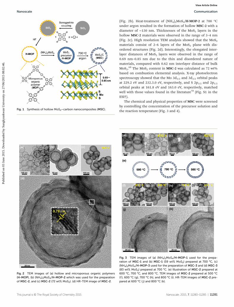
(Fig. 2b). Heat-treatment of (NH4)2MoS4/H-MOP-2 at 700 °Cunder argon resulted in the formation of hollow MSC-2 with adiameter of ∼130 nm. Thicknesses of the MoS2 layers in thehollow MSC-2 materials were observed in the range of 3–4 nm(Fig. 2c). High resolution TEM analysis showed that the MoS2materials consist of 2–6 layers of the MoS2 plane with dis-ordered structures (Fig. 2d). Interestingly, the elongated inter-layer distances of MoS2 layers were observed in the range of0.69 nm–0.85 nm due to the thin and disordered nature ofmaterials, compared with 0.62 nm interlayer distance of bulkMoS2.
6b The MoS2 content in MSC-2 was calculated as 72 wt%based on combustion elemental analysis. X-ray photoelectronspectroscopy showed that the Mo 3d5/2 and 3d3/2 orbital peaksat 229.2 eV and 232.3.0 eV, respectively, and S 2p3/2 and 2p1/2orbital peaks at 161.8 eV and 163.0 eV, respectively, matchedwell with those values found in the literature7b (Fig. S1 in theESI†).
The chemical and physical properties of MSC were screenedby controlling the concentration of the precursor solution andthe reaction temperature (Fig. 3 and 4).Fig. 1 Synthesis of hollow MoS2–carbon nanocomposites (MSC).
Fig. 2 TEM images of (a) hollow and microporous organic polymers(H-MOP), (b) (NH4)2MoS4/H-MOP-2 which was used for the preparationof MSC-2, and (c) MSC-2 (72 wt% MoS2). (d) HR-TEM image of MSC-2.
Fig. 3 TEM images of (a) (NH4)2MoS4/H-MOP-1 used for the prepa-ration of MSC-1 and (b) MSC-1 (59 wt% MoS2) prepared at 700 °C, (c)(NH4)2MoS4/H-MOP-3 used for the preparation of MSC-3 and (d) MSC-3(83 wt% MoS2) prepared at 700 °C. (e) Illustration of MSC-2 prepared at600 °C, 700 °C, and 800 °C. TEM images of MSC-2 prepared at 500 °C(f ), 600 °C (g), 700 °C (h), and 800 °C (i). HR-TEM images of MSC-2 pre-pared at 600 °C ( j) and 800 °C (k).
Nanoscale Communication
This journal is © The Royal Society of Chemistry 2015 Nanoscale, 2015, 7, 11280–11285 | 11281
Publ
ishe
d on
03
June
201
5. D
ownl
oade
d by
Sun
gkyu
nkw
an U
nive
rsity
on
27/0
6/20
15 0
8:02
:46.
View Article Online

When the concentration of (NH4)2MoS4 was reduced from0.022 M to 0.011 M, the loading thickness of (NH4)2MoS4 inH-MOP decreased from ∼5 nm to ∼3 nm (Fig. 3a). The heattreatment of (NH4)2MoS4/H-MOP-1 resulted in MSC-1 with
59 wt% content (based on elemental analysis) and ∼2.5 nmthickness of MoS2 materials (Fig. 3b). When the concentrationof (NH4)2MoS4 increased to 0.044 M, much more (NH4)2MoS4was loaded onto H-MOP with ∼12 nm thickness (Fig. 3c). Theheat treatment of (NH4)2MoS4/H-MOP-3 resulted in MSC-3with 83 wt% content and ∼6 nm thickness of MoS2 materials(Fig. 3d).15
According to N2 isotherm analysis, the surface area ofmaterials decreased gradually from 730 m2 g−1 (pristineH-MOP) to 239 m2 g−1 ((NH4)2MoS4/H-MOP-1), 71 m2 g−1
((NH4)2MoS4/H-MOP-2), and 19 m2 g−1 ((NH4)2MoS4/H-MOP-3)by loading of (NH4)2MoS4 (Fig. 4a and Table 1). Total porevolume decreased from 1.27 cm3 g−1 (micropore volume,0.17 cm3 g−1, H-MOP) to 0.79 cm3 g−1 (micropore volume,0.05 cm3 g−1, (NH4)2MoS4/H-MOP-1), 0.29 cm3 g−1 (microporevolume, 0.02 cm3 g−1, (NH4)2MoS4/H-MOP-2), and 0.10 cm3 g−1
(micropore volume, 0 cm3 g−1, (NH4)2MoS4/H-MOP-3), showingthat the MoS2 precursor was loaded in the pores of H-MOP.The surface areas of MSC-1, MSC-2, and MSC-3 were measuredas 310 m2 g−1, 44 m2 g−1, and 23 m2 g−1, respectively (Fig. 4band c and Table 1).
The formation of the MoS2 material in MSC-2 was furtherinvestigated by varying the heat treatment temperature(Fig. 3e–k). As the reaction temperature increased from 500 °Cto 600 °C, 700 °C, and 800 °C, the disordered part and theelongated interlayer distance of MoS2 gradually decreased(Fig. 3j and k). This trend was confirmed by powder X-ray diffr-action studies (PXRD). As shown in the PXRD patterns inFig. 4d, H-MOP and (NH4)2MoS4/H-MOP are amorphous. Asreported in the literature, three diffraction peaks from (002),(100) and (110) crystal planes of 2H MoS2 (JCPDS # 37-1492) inMSC materials were observed dominantly due to the uniqueshape effect of MoS2 materials.7 As the reaction temperatureincreased, the (002) diffraction peaks (indicated by an arrow inFig. 4d) of MoS2 in materials were sharpened and shiftedgradually to the (002) location of bulk MoS2, indicating thatthe interlayer distance decreases with an increase of crystalli-nity due to the more facile packing of the MoS2 layers.
16
Considering the nano-scale and disordered nature of MoS2in MSC materials, we studied the electrochemical performance
Fig. 4 (a) N2 isotherm curves at 77 K and pore size distribution diagram(inset, based on the DFT method) of H-MOP (black line), and(NH4)2MoS4-loaded H-MOP materials for MSC-1 (blue), MSC-2 (red),and MSC-3 (green). (b) Pore size distribution diagrams (the DFT method)and (c) N2 isotherm curves at 77 K of for MSC-1 (blue), MSC-2 (red), andMSC-3 (green). (d) PXRD patterns of H-MOP, (NH4)2MoS4-loadedH-MOP materials, MSC-1, MSC-2, and MSC-3. The arrow in PXRD pat-terns indicates the shift of (002) peaks.
Table 1 Properties of materials studied in this work
MaterialMoS2 content(wt%)
SBETd
(m2 g−1)Vtot
e
(cm3 g−1)Vmic
f
(cm3 g−1)Discharge capacityg
(mA h g−1)
H-MOP — 730 1.27 0.17 —(NH4)2MoS4/H-MOP-1a — 239 0.79 0.05 —(NH4)2MoS4/H-MOP-2b — 71 0.29 0.02 —(NH4)2MoS4/H-MOP-3c — 19 0.1 0 —MSC-1 59 310 0.48 0.1 438MSC-2 72 44 0.2 0.01 802MSC-3 83 23 0.1 0 629
a The material was obtained using 0.011 M (NH4)2MoS4 solution (see the Experimental section in the ESI for the detailed procedure) and used forthe preparation of MSC-1. b The material was obtained using 0.022 M (NH4)2MoS4 solution and used for the preparation of MSC-2. c The materialwas obtained using 0.044 M (NH4)2MoS4 solution and used for the preparation of MSC-3. d Specific surface area by BET plot. e Total pore volume.fMicropore (<2 nm) volume by t-plot. g The value obtained after 30 cycles at 50 mA g−1 current density.
Communication Nanoscale
11282 | Nanoscale, 2015, 7, 11280–11285 This journal is © The Royal Society of Chemistry 2015
Publ
ishe
d on
03
June
201
5. D
ownl
oade
d by
Sun
gkyu
nkw
an U
nive
rsity
on
27/0
6/20
15 0
8:02
:46.
View Article Online

of MSC materials for lithium ion batteries. Table 1 and Fig. 5and S2–7 in the ESI† summarize the results.
All MSC materials (MSC-1: 59 wt% MoS2, MSC-2: 72 wt%MoS2, MSC-3: 83 wt% MoS2) showed quite stable electrochemi-cal performance for lithium ion batteries (Fig. 5a). Among theMSC materials, MSC-2 showed the highest reversible dischargecapacities with 817 mA h g−1 at the 2nd cycle and 802 mA hg−1 after 30 cycles (98% retention of the capacity of the 2ndcycle) at 50 mA g−1 current density. The Coulombic efficiencyreached 97% at the 3rd cycle and maintained higher values insuccessive runs. MSC-1 and MSC-3 showed dischargecapacities of 438 mA h g−1 and 629 mA h g−1 after 30 cycles,
respectively. As the MoS2 content in MSC increased, its thick-ness increased, inducing an elongated diffusion pathway andan increase of charge transfer resistance (Fig. S3 and 4 in theESI†). On the other hand, as the carbon content increased, thestorage capacity decreased with the reduced MoS2 content.Thus, the optimal chemical composition of MoS2 and carbonis important to maximize the storage capacity. A similar obser-vation in MoS2–carbon nanocomposites was reported in theliterature.17
The electrochemical performance of MSC-2 materials pre-pared at different reaction temperatures is shown in Fig. S2 inthe ESI.† The MSC-2 materials prepared at 500 °C (MSC-2-500)showed incomplete formation of MoS2 in the MSC-2 materials,hence the MSC-2 materials were leached into the electrolytesolution. Among the MSC-2 materials prepared at 600 °C(MSC-2-600, 699 mA h g−1 capacity after 30 cycles), 700 °C, and800 °C (MSC-2-800, 643 mA h g−1 capacity after 30 cycles), theMSC-2 prepared at 700 °C (MSC-2-700), showed the best electro-chemical performance with a 802 mA h g−1 capacity after 30cycles. This implies that the appropriately disordered structureof MoS2 in MSC-2 facilitates the electrochemical reactionsefficiently (Fig. 3e–k).6b,16
Recently, the lithium storage process of MoS2 nanocompo-sites was reviewed by Mitlin et al.18 They suggested that revers-ible lithium storage of MoS2-based electrode materials fromthe 2nd run is attributable to electrochemical inter-conversionbetween the generated Li2S and sulfur.18,19 As shown in thecharge/discharge profiles in Fig. 5b and S5 in the ESI,† MSC-2showed voltage plateaus at ∼1.1 V and ∼0.6 V (vs. Li+/Li) in thefirst discharge curve, which is attributed to lithium insertioninto the MoS2 layers and successive chemical conversion to Moand Li2S, respectively. The disappearance of the voltage pla-teaus at ∼0.6 V (vs. Li+/Li) from the 2nd discharge curve ofMSC-2 and the appearance of new voltage plateaus at ∼2.2 V(vs. Li+/Li) support the Li2S/S based lithium storage mechan-ism.18 Cyclic voltammogram of the MSC-2 showed two vividreduction peaks at 1.0 V and 0.45 V (vs. Li+/Li) in the first dis-charge process, which corresponds to the insertion of lithiuminto MoS2 and the reduction of LixMoS2 to Mo and Li2S, respecti-vely18 (Fig. 5c and S5 in the ESI†). In the second and the suc-cessive cycles, cyclic voltammograms showed reversible redoxpeaks at 2.2 V (vs. Li+/Li), which correspond to the oxidation ofLi2S to sulfur and reversible reduction of sulfur to Li2S.
18
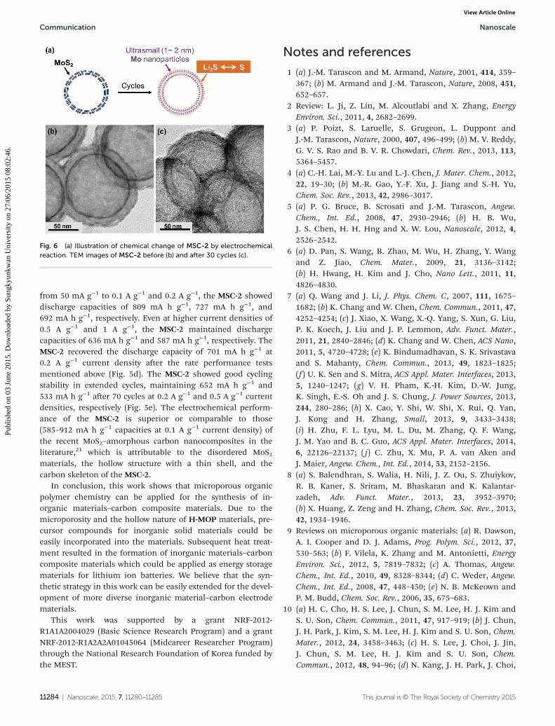
Considering this, the layered MoS2 morphology may notsurvive after the cycling. The MSC-2 materials retrieved after30 cycles were investigated by TEM studies (Fig. 6 and S6 and 7in the ESI†). The basic hollow morphology of materials wasfound to be maintained. Interestingly, the original 2D MoS2materials in the MSC-2 were completely converted to ultra-small Mo rich particles20 of 1–2 nm sizes after electrochemicalreactions. It can be presumed that the hollow carbon and thegenerated ultrasmall Mo particles of the MSC-2 might serve asa structural skeleton and a binder for the reversible conversionbetween sulfur and Li2S.
18
The MSC-2 showed excellent rate performance (Fig. 5dand S4 in the ESI†). As the current densities increased
Fig. 5 (a) Discharge capacities of MSC-1, MSC-2, and MSC-3 at 50 mAg−1 current density and Coulombic efficiencies (violet line) of MSC-2. (b)Charge–discharge curves, (c) cyclic voltammograms (scan rate: 50 mVs−1), (d) rate performance, and (e) cycling performance in the extendedcycle of MSC-2 (displayed from the 2nd cycle).
Nanoscale Communication
This journal is © The Royal Society of Chemistry 2015 Nanoscale, 2015, 7, 11280–11285 | 11283
Publ
ishe
d on
03
June
201
5. D
ownl
oade
d by
Sun
gkyu
nkw
an U
nive
rsity
on
27/0
6/20
15 0
8:02
:46.
View Article Online
from 50 mA g−1 to 0.1 A g−1 and 0.2 A g−1, the MSC-2 showeddischarge capacities of 809 mA h g−1, 727 mA h g−1, and692 mA h g−1, respectively. Even at higher current densities of0.5 A g−1 and 1 A g−1, the MSC-2 maintained dischargecapacities of 636 mA h g−1 and 587 mA h g−1, respectively. TheMSC-2 recovered the discharge capacity of 701 mA h g−1 at0.2 A g−1 current density after the rate performance testsmentioned above (Fig. 5d). The MSC-2 showed good cyclingstability in extended cycles, maintaining 652 mA h g−1 and533 mA h g−1 after 70 cycles at 0.2 A g−1 and 0.5 A g−1 currentdensities, respectively (Fig. 5e). The electrochemical perform-ance of the MSC-2 is superior or comparable to those(585–912 mA h g−1 capacities at 0.1 A g−1 current density) ofthe recent MoS2–amorphous carbon nanocomposites in theliterature,21 which is attributable to the disordered MoS2materials, the hollow structure with a thin shell, and thecarbon skeleton of the MSC-2.
In conclusion, this work shows that microporous organicpolymer chemistry can be applied for the synthesis of in-organic materials–carbon composite materials. Due to themicroporosity and the hollow nature of H-MOP materials, pre-cursor compounds for inorganic solid materials could beeasily incorporated into the materials. Subsequent heat treat-ment resulted in the formation of inorganic materials–carboncomposite materials which could be applied as energy storagematerials for lithium ion batteries. We believe that the syn-thetic strategy in this work can be easily extended for the devel-opment of more diverse inorganic material–carbon electrodematerials.
This work was supported by a grant NRF-2012-R1A1A2004029 (Basic Science Research Program) and a grantNRF-2012-R1A2A2A01045064 (Midcareer Researcher Program)through the National Research Foundation of Korea funded bythe MEST.
Notes and references
1 (a) J.-M. Tarascon and M. Armand, Nature, 2001, 414, 359–367; (b) M. Armand and J.-M. Tarascon, Nature, 2008, 451,652–657.
2 Review: L. Ji, Z. Lin, M. Alcoutlabi and X. Zhang, EnergyEnviron. Sci., 2011, 4, 2682–2699.
3 (a) P. Poizt, S. Laruelle, S. Grugeon, L. Duppont andJ.-M. Tarascon, Nature, 2000, 407, 496–499; (b) M. V. Reddy,G. V. S. Rao and B. V. R. Chowdari, Chem. Rev., 2013, 113,5364–5457.
4 (a) C.-H. Lai, M.-Y. Lu and L.-J. Chen, J. Mater. Chem., 2012,22, 19–30; (b) M.-R. Gao, Y.-F. Xu, J. Jiang and S.-H. Yu,Chem. Soc. Rev., 2013, 42, 2986–3017.
5 (a) P. G. Bruce, B. Scrosati and J.-M. Tarascon, Angew.Chem., Int. Ed., 2008, 47, 2930–2946; (b) H. B. Wu,J. S. Chen, H. H. Hng and X. W. Lou, Nanoscale, 2012, 4,2526–2542.
6 (a) D. Pan, S. Wang, B. Zhao, M. Wu, H. Zhang, Y. Wangand Z. Jiao, Chem. Mater., 2009, 21, 3136–3142;(b) H. Hwang, H. Kim and J. Cho, Nano Lett., 2011, 11,4826–4830.
7 (a) Q. Wang and J. Li, J. Phys. Chem. C, 2007, 111, 1675–1682; (b) K. Chang and W. Chen, Chem. Commun., 2011, 47,4252–4254; (c) J. Xiao, X. Wang, X.-Q. Yang, S. Xun, G. Liu,P. K. Koech, J. Liu and J. P. Lemmon, Adv. Funct. Mater.,2011, 21, 2840–2846; (d) K. Chang and W. Chen, ACS Nano,2011, 5, 4720–4728; (e) K. Bindumadhavan, S. K. Srivastavaand S. Mahanty, Chem. Commun., 2013, 49, 1823–1825;(f ) U. K. Sen and S. Mitra, ACS Appl. Mater. Interfaces, 2013,5, 1240–1247; (g) V. H. Pham, K.-H. Kim, D.-W. Jung,K. Singh, E.-S. Oh and J. S. Chung, J. Power Sources, 2013,244, 280–286; (h) X. Cao, Y. Shi, W. Shi, X. Rui, Q. Yan,J. Kong and H. Zhang, Small, 2013, 9, 3433–3438;(i) H. Zhu, F. L. Lyu, M. L. Du, M. Zhang, Q. F. Wang,J. M. Yao and B. C. Guo, ACS Appl. Mater. Interfaces, 2014,6, 22126–22137; ( j) C. Zhu, X. Mu, P. A. van Aken andJ. Maier, Angew. Chem., Int. Ed., 2014, 53, 2152–2156.
8 (a) S. Balendhran, S. Walia, H. Nili, J. Z. Ou, S. Zhuiykov,R. B. Kaner, S. Sriram, M. Bhaskaran and K. Kalantar-zadeh, Adv. Funct. Mater., 2013, 23, 3952–3970;(b) X. Huang, Z. Zeng and H. Zhang, Chem. Soc. Rev., 2013,42, 1934–1946.
9 Reviews on microporous organic materials: (a) R. Dawson,A. I. Cooper and D. J. Adams, Prog. Polym. Sci., 2012, 37,530–563; (b) F. Vilela, K. Zhang and M. Antonietti, EnergyEnviron. Sci., 2012, 5, 7819–7832; (c) A. Thomas, Angew.Chem., Int. Ed., 2010, 49, 8328–8344; (d) C. Weder, Angew.Chem., Int. Ed., 2008, 47, 448–450; (e) N. B. McKeown andP. M. Budd, Chem. Soc. Rev., 2006, 35, 675–683.
10 (a) H. C. Cho, H. S. Lee, J. Chun, S. M. Lee, H. J. Kim andS. U. Son, Chem. Commun., 2011, 47, 917–919; (b) J. Chun,J. H. Park, J. Kim, S. M. Lee, H. J. Kim and S. U. Son, Chem.Mater., 2012, 24, 3458–3463; (c) H. S. Lee, J. Choi, J. Jin,J. Chun, S. M. Lee, H. J. Kim and S. U. Son, Chem.Commun., 2012, 48, 94–96; (d) N. Kang, J. H. Park, J. Choi,
Fig. 6 (a) Illustration of chemical change of MSC-2 by electrochemicalreaction. TEM images of MSC-2 before (b) and after 30 cycles (c).
Communication Nanoscale
11284 | Nanoscale, 2015, 7, 11280–11285 This journal is © The Royal Society of Chemistry 2015
Publ
ishe
d on
03
June
201
5. D
ownl
oade
d by
Sun
gkyu
nkw
an U
nive
rsity
on
27/0
6/20
15 0
8:02
:46.
View Article Online
J. Jin, J. Chun, I. G. Jung, J. Jeong, J.-G. Park, S. M. Lee,H. J. Kim and S. U. Son, Angew. Chem., Int. Ed., 2012, 51,6626–6630; (e) J. Chun, S. Kang, S. M. Lee, H. J. Kim andS. U. Son, J. Mater. Chem. A, 2013, 1, 5517–5523;(f ) N. Kang, J. H. Park, K. C. Ko, J. Chun, E. Kim,H. W. Shin, S. M. Lee, H. J. Kim, T. K. Ahn, J. Y. Lee andS. U. Son, Angew. Chem., Int. Ed., 2013, 52, 6228–6232.
11 (a) N. Kang, J. H. Park, M. Jin, N. Park, S. M. Lee, H. J. Kim,J. M. Kim and S. U. Son, J. Am. Chem. Soc., 2013, 135,19115–19118; (b) J. Chun, S. Kang, N. Park, E. J. Park,X. Jin, K.-D. Kim, H. O. Seo, S. M. Lee, H. J. Kim,W. H. Kwon, Y.-K. Park, J. M. Kim, Y. D. Kim and S. U. Son,J. Am. Chem. Soc., 2014, 136, 6786–6789; (c) J. Jin, B. Kim,N. Park, S. Kang, J. H. Park, S. M. Lee, H. J. Kim andS. U. Son, Chem. Commun., 2014, 50, 14885–14888;(d) J. Yoo, N. Park, J. H. Park, J. H. Park, S. Kang, S. M. Lee,H. J. Kim, H. Jo, J.-G. Park and S. U. Son, ACS Catal., 2015,5, 350–355.
12 (a) L. Hao, X. Li and L. Zhi, Adv. Mater., 2013, 25, 3899–3904; (b) B. Lim, J. Jin, J. Yoo, S. Y. Han, K. Kim, S. Kang,N. Park, S. M. Lee, H. J. Kim and S. U. Son, Chem.Commun., 2014, 50, 7723–7726.
13 (a) K. H. Park, K. Jang and S. U. Son, Angew. Chem., Int. Ed.,2006, 45, 4608–4612; (b) K. H. Park, K. Jang, S. Kim,H. J. Kim and S. U. Son, J. Am. Chem. Soc., 2006, 128,14780–14781; (c) K. H. Park, K. Jang and S. U. Son, Angew.Chem., Int. Ed., 2007, 46, 1152–1155; (d) K. H. Park, J. Choi,H. J. Kim, D.-H. Oh, J. R. Ahn and S. U. Son, Small, 2008, 4,945–850; (e) K. Jang, H. J. Kim and S. U. Son, Chem. Mater.,2010, 22, 1273–1275; (f ) J. Choi, J. Jin, I. G. Jung, J. M. Kim,H. J. Kim and S. U. Son, Chem. Commun., 2011, 47, 5241–5243; (g) J. Xu, K. Jang, J. Choi, J. Jin, J. H. Park, H. J. Kim,D.-H. Oh, J. R. Ahn and S. U. Son, Chem. Commun., 2012,48, 6244–6246.
14 Y. Hou, A. B. Laursen, J. Zhang, G. Zhang, Y. Zhu, X. Wang,S. Dahl and I. Chorkendorff, Angew. Chem., Int. Ed., 2013,52, 3621–3625.
15 When the concentration of (NH4)2MoS4 was increased to0.088 M, the heat treatment of (NH4)2MoS4/H-MOP resultedin 84 wt% MoS2 content in MSC.
16 H. Liu, D. Su, R. Zhou, B. Sun, G. Wang and S. Z. Qiao, Adv.Energy Mater., 2012, 2, 970–975.
17 S. K. Das, R. Mallavajula, N. Jayaprakash and L. A. Archer,J. Mater. Chem., 2012, 22, 12988–12992.
18 The potential for the sulfur reduction reaction by lithium,S + 2Li+ + 2e− → Li2S, is known as ∼2.2 V (vs. Li/Li+).T. Stephenson, Z. Li, B. Olsen and D. Mitlin, EnergyEnviron. Sci., 2014, 7, 209–231.
19 partial electrochemical contribution of carbon and Mo par-ticles in the lithium storage process has been suggested inthe literature (ref. 18).
20 For TEM analysis on cycled MSC-2, the materials weredetached from the Cu electrode by sonication and washedwith ethanol. In this sampling process, Li2S might beextracted from the materials by the solvent. Thus, electronenergy loss and energy dispersive X-ray spectroscopy onultrathin particles in the cycled MSC-2 exclusively showedMo contents (Fig. S7 in the ESI†).
21 (a) H. Li, W. Li, L. Ma, W. Chen and J. Wang, J. AlloysCompd., 2009, 471, 442–447; (b) J. Xiao, D. Choi,L. Cosimbescu, P. Koech, J. Liu and J. P. Lemmon, Chem.Mater., 2010, 22, 4522–4524; (c) K. Chang, W. Chen, L. Ma,H. Li, H. Li, F. Huang, Z. Xu, Q. Zhang and J.-Y. Lee,J. Mater. Chem., 2011, 21, 6251–6257; (d) S. Ding, D. Zhang,J. S. Chen and X. W. Lou, Nanoscale, 2012, 4, 95–98;(e) X. Zhou, L.-J. Wan and Y.-G. Guo, Nanoscale, 2012, 4,5868–5871; (f ) L. Hu, Y. Ren, H. Yang and Q. Xu, ACS Appl.Mater. Interfaces, 2014, 6, 14644–14652.
Nanoscale Communication
This journal is © The Royal Society of Chemistry 2015 Nanoscale, 2015, 7, 11280–11285 | 11285
Publ
ishe
d on
03
June
201
5. D
ownl
oade
d by
Sun
gkyu
nkw
an U
nive
rsity
on
27/0
6/20
15 0
8:02
:46.
View Article Online